
TM30 - Tubular motor CHAMBERLAIN - Free user manual and instructions
Find the device manual for free TM30 CHAMBERLAIN in PDF.
User questions about TM30 CHAMBERLAIN
0 question about this device. Answer the ones you know or ask your own.
Ask a new question about this device
Download the instructions for your Tubular motor in PDF format for free! Find your manual TM30 - CHAMBERLAIN and take your electronic device back in hand. On this page are published all the documents necessary for the use of your device. TM30 by CHAMBERLAIN.
USER MANUAL TM30 CHAMBERLAIN
IMPORTANT SAFETY RULES - SAVE THESE INSTRUCTIONS

These safety alert symbols mean Caution - a personal safety or property damage instruction. This tubular motor is designed and tested to offer reasonable safe service provided it is installed and operated in strict accordance with the following safety rules.

Failure to comply with the following instructions may result in serious personal injury or property damage.


WARNING: IT IS IMPORTANT FOR THE SAFETY OF PERSONS TO FOLLOW THESE INSTRUCTIONS. SAVE THESE INSTRUCTIONS.

To avoid injury, completely lower the shutter before loosening the screws in the tube end of the shutter.

Installation and wiring must be in compliance with your local building and electrical codes.

Disconnect the power supply to the shutter motor before commencing any repairs

A suitable power phase jumper (full-pole disconnect with 3 mm contact opening gap) must be fitted in the power supply..

Any damaged power supply wiring must be replaced by the manufacturer or the manufacturer's customer service agent.

Do not allow children to play with fixed controls. Keep remote controls away from children.

Frequently examine the installation for imbalance or signs of wear. Do not use if repair or adjustment is necessary.

Watch the moving shutter or awning and keep away until the shutter has completely stopped.

Ensure that the motor is accessible at all times following installation.

Carton Contents
(1) TM10, TM20, TM30 or TM50 Tubular Motor
(2) Screw M5x15 with washer (1 each)
TM20, TM30, TM50
Screw 4.8x22 with washer (1 each) - TM10
(3) Tube Adapter Set, 60mm octagonal TM20, TM30, TM50
(4) Tube Adapter Set, 40mm octagonal TM10
(5) Square tube bracket (1) or alternatively
(5.1) square tube pin (1) and 2 screws
(6) Mounting bracket (1)
(7) Cotter pin (1)
(8) Screw 3,9 x 6,5 (3) TM20, TM30, TM50 to armoured bracket
(9) Motor bracket TM10 (2 parts)
(10) Mounting screws (2) TM10 for Motor bracket
(11) adjuster pin
Before You Begin:
- Carefully read all the information contained in this Owner's Manual before beginning installation procedures.
- Check the shutter to be sure it is not broken or damaged, and that it opens and closes smoothly.
- Determine whether the motor needs to be installed on the left side, (1) or the right side, (2) of the shutter. Install it on the side where the manual pull is located. Close the shutter.
- Ensure that the motor can be pushed in as far as the stop. The limit switch is controlled by the plastic ring which must be pushed fully on.
Warranty for Tubular Motor
Chamberlain GmbH warrants to the first retail purchaser of this product that the product shall be free from any defect in materials and/or workmanship for a period of 24 full months (2 years) from the date of purchase for TM10, TM20, TM30 or TM50 Series Models. Upon receipt of the product, the first retail purchaser is under obligation to check the product for any visible defects.
Conditions: The warranty is strictly limited to the reparation or replacement of the parts of this product which are found to be defective and does not cover the costs or risks of transportation of the defective parts or products.
This warranty does not cover non-defect damage caused by unreasonable use (including use not in complete accordance with Chamberlain's instructions for installation, operation and care; failure to provide necessary maintenance and adjustment; or any adaptations of or alterations to the products), labor charges for dismantling or reinstalling of a repaired or replaced unit or replacement batteries.
A product under warranty which is determined to be defective in materials and/or workmanship will be repaired or replaced (at Chamberlain's option) at no cost to the owner for the repair and/or replacement parts and/or product. Defective parts will be repaired or replaced with new or factory rebuilt parts at Chamberlain's option.
If, during the warranty period, the product appears as though it may be defective, contact your original place of purchase.
This warranty does not affect the purchaser's statutory rights under applicable national legislation in force nor the purchaser's rights against the retailer arising from their sales purchase contract. In the absence of applicable national or EC legislation, this warranty will be the purchaser's sole and exclusive remedy, and neither Chamberlain GmbH nor its affiliates or distributors shall be liable for any incidental or consequential images for any express or implied warranty relating to this product.
No representative or person is authorized to assume for Chamberlain GmbH any other liability in connection with the sale of this product.
| Technical Data | ||||
| Typ | TM10 | TM20 | TM30 | TM50 |
| Power | 125 Watts | 155 Watts | 185 Watts | 235 Watts |
| Power Supply | 230V / 50Hz, cable 2m | 230V / 50Hz, cable 2m | 230V / 50Hz, cable 2m | 230V / 50Hz, cable 2m |
| Torque | 10Nm | 15Nm | 20Nm | 40Nm |
| Pulling Force | 18kg (40mm Tube) | 25kg (60mm Tube) | 35kg (60mm Tube) | 72kg (60mm Tube) |
| R.P.M. | 14 U/Min. | 18 U/Min. | 18 U/Min. | 18 U/Min. |
INSTALLATION
Rough- in or install conduit pipe to the connector box for the electrical connecting line according to local building and electrical codes.
Push the tube adapter (3/4) onto the motor (1), and secure the drive adapter with the fixing parts (2) supplied. Insert the square tube bracket (5) into the recess in the motor head, and apply gentle pressure until it engages. If a square tube pin (5.1) has been supplied, secure this with the screws. On model TM10, the motor bracket (9) is secured by means of 2 motor bracket mounting screws (10).
Fully unroll the shutter (a). Remove the shutter material from the tube (b). Remove the manual control (c).
D Remove the tube.
Push the motor (1) completely into the tube. The limit switch operates only if the drive unit is fully inserted. Ensure that the adapter ring is pushed fully home. Do not force it or strike it. Do not damage the tubular motor by drilling!
F Proceed according to the specific requirements for left-sided (a) or right-sided (b) operation:
G Secure the mounting bracket (6) to the wall (10) (use suitable screws and plugs).
Insert the square tube bracket on the motor (1) into the mounting bracket (6) and secure with the cotter pin (7).
Make sure the set screws for the limit adjustments (beneath the mounting bracket) are accessible.
Don't return the shutter material to the tube yet!

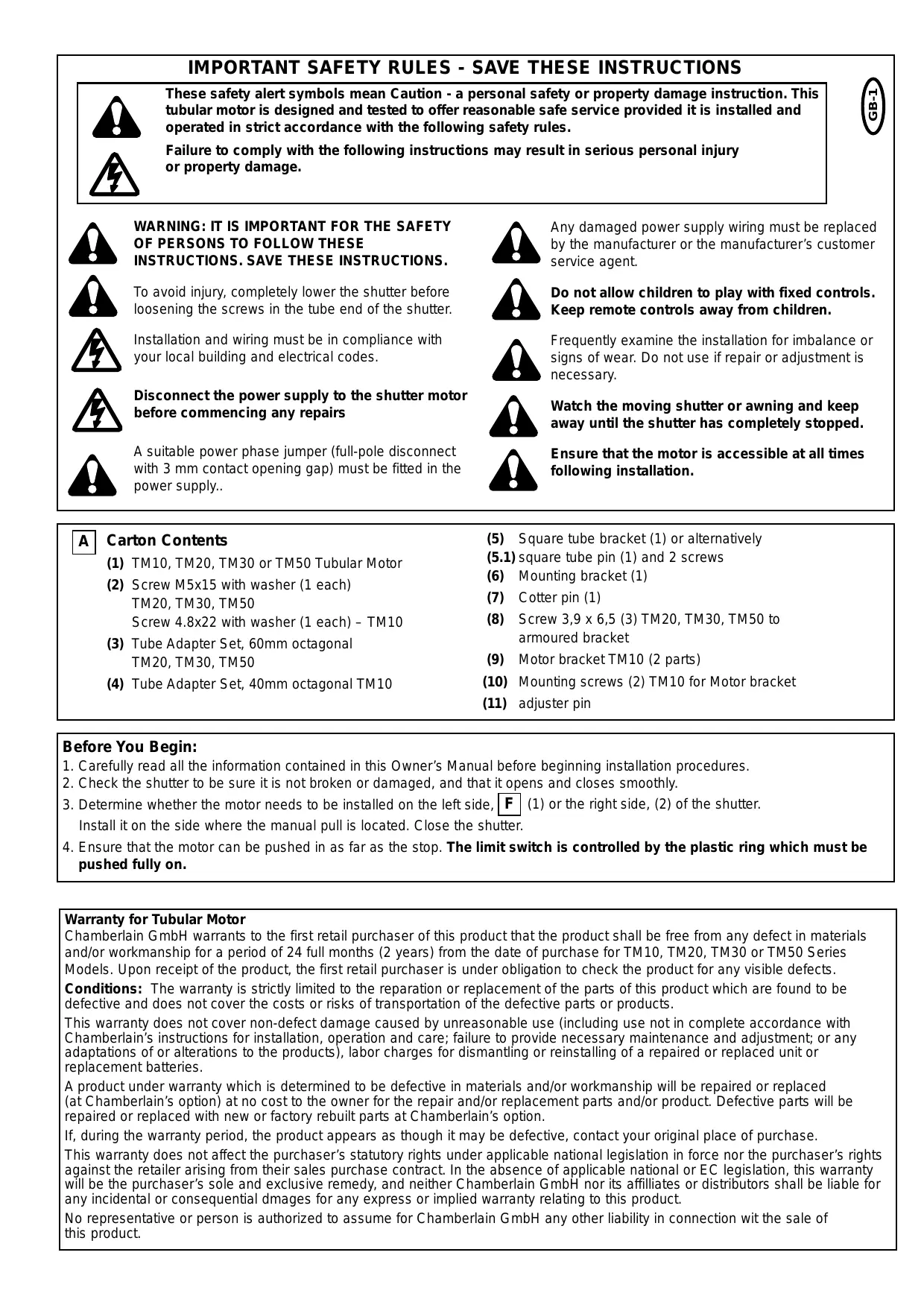
SETTING THE LIMITS
Procedure for Adjusting "Open" and "Cose" Positions
(refer to figure I for lefthanded installation)
1 Limit Setting for "Shutter Open"
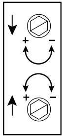
- = increase closing travel
- = decrease closing travel
2 Limit Setting for "Shutter Close"
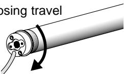
- = increase opening travel
- = decrease opening travel

Please observe that the limitis of the motor only operate in a complete installation.
Read the following instructions carefully before making any open or close limit adjustments.
To attach the shutter material on the tube, use ONLY the 3.9 × 6.5 mounting screws included (TM20, TM30, TM50). Otherwise, the drive might be damaged by screws which are too long.
This instruction applies particularly to model TM10 (no screws included). Use the appropriate fixing parts to secure the shutter material to the tube. The drive may be damaged by using screws which are too long.
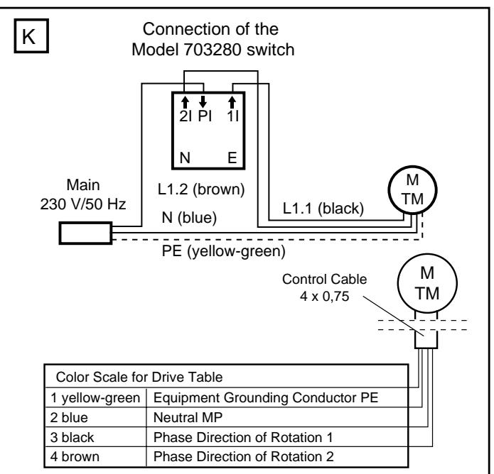
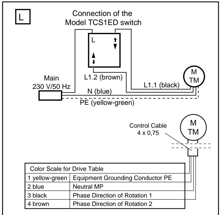
ELECTRICAL CONNECTION

Never connect more than one motor to a timer or wall switch without using a central module - (h) (available as an accessory), i.e. one central
module is required for each connected motor.
The illustration also shows the wall bracket on the drive side (b), the motor drive (a); the steel tube (c); the end cap (d); and the opposite wall bearing (e).
For a left-side motor installation, follow the wiring diagram exactly as shown in the control accessory package.
For the correct direction of rotation in a right-side motor installation, electrical wires (brown & black) must be reversed between the control accessory and the motor. (See instructions packed with the accessory you have chosen).
Have the electrical hook-up done by a qualified electrician in compliance with your local electrical code.
TCS1ED Rocker switch (f)
TCT2ED Programmable Timer (g)
TCTX2ED Remote Control Wall Switch (w/o fig.)
TCTRX2ED Programmable Timer with Integrated Receiver (w/o fig.)
TCRX3ED Rolling Shutter Receiver (w/o fig.)
WTMTZ Central Module (h)
Additional accessories can be found in section M on page 3.
IF ADJUSTMENTS ARE NEEDED, PROCEED AS FOLLOWS:
LIMIT ADJUSTMENT SCREW #1 - OPEN
Run the motor through an open cycle.
If motor stops before shutter is fully opened:
Turn set screw #1 toward + and open the shutter until desired position is reached.
If motor stops after shutter is fully opened:
Close shutter below desired position. Turn set screw #1 toward – and open shutter again. Repeat this step as often as necessary to reach the desired position
LIMIT ADJUSMENT SCREW #2 - CLOSE
Run the motor through a close cycle. Attach the shutter material to the tube.
If motor stops too soon (before shutter is fully closed):
Turn set screw #2 toward + and close shutter again, until desired position is reached.
If motor stops after shutter is fully closed:
Retract shutter above desired position. Turn set screw #2 toward – and close shutter again. Repeat this step as often as necessary to reach the desired position.
TROUBLE SHOOTING
Motor does not run
- Public electricity supply failure. Check with a neighbor.
- Circuit breaker has tripped or fuse is blown. Check house overload protector. If necessary, have an authorized electrician redistribute the load.
- The switch is defective. Have it checked by an authorized electrician and replaced if necessary.
- Repeated operation may have tripped the motor overload protector switch. Wait 15 minutes and try again.
Motor runs intermittently
- Have the wiring connection between switch and motor checked by an authorized electrician. Replace if necessary.
Motor does not shut off
- Check to be sure tube adapter is positioned all the way up to the stop on the tube.
- Check to be sure the motor has been inserted all the way into the tube.
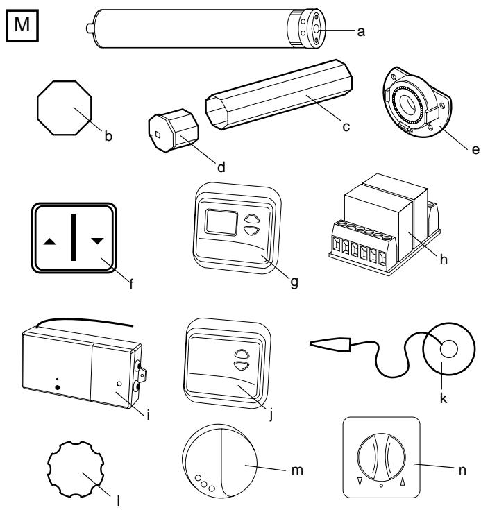
| No. | Part | Description |
| (a) | 704636 | Motor TM10 |
| 120785ASA | Motor TM20 | |
| 120758ASA | Motor TM30 | |
| 120756ASA | Motor TM50 | |
| (b) | TAO70ASA | Tube adapter octagonal 70mm (Not for TM10) |
| (c) | WT860-1 | Octagonal tube 60mm with endcap - 1m |
| WT860-2 | Octagonal tube 60mm with endcap - 2m | |
| WT860-3 | Octagonal tube 60mm with endcap - 3m | |
| (d) | 120995 | Endcap for octagonal tube 60mm |
| (e) | 121084 | Universal wall bearing for WT860 |
| (f) | TCS1ED | Wall Switch (Rocker switch) |
| (g) | TCT2ED | Programmable Timer |
| TCTRX2ED | Programmable Timer with integrated Receiver | |
| TCTTX2ED | Programmable Timer with integrated Transmitter | |
| (h) | WTMZ1 | Central Module |
| (i) | TCRX3ED | Rolling Shutter Remote Control Receiver |
| (j) | TCTX2ED | Remote Control Wall Switch |
| TCRX2ED | Rolling Shutter Control with integrated Receiver | |
| (k) | WTMLS1 | Light Sensor |
| (l) | TAP65ASA | Tube adapter profile shaft 65mm (Not for TM10) |
| (m) | TCLS1ED | Remote Control Light and Glass Breakage Sensor |
| (n) | 703280 | Switch - flush mount |
| 708218 | Accessory pack TM10 - Motor bracket (w/o figure) | |
| 708223 | Accessory pack TM10 - Adapter (w/o figure) | |
| 041TM707008 | Accessory pack TM20, TM30, TM50 (w/o figure) | |
| TAM120155 | Tube adapter awning 78mm, TM50 only (w/o figure) | |
| TAM120162 | Tube adapter awning 85mm, TM50 only (w/o figure) |