
RPD25 - Tubular motor CHAMBERLAIN - Free user manual and instructions
Find the device manual for free RPD25 CHAMBERLAIN in PDF.
User questions about RPD25 CHAMBERLAIN
0 question about this device. Answer the ones you know or ask your own.
Ask a new question about this device
Download the instructions for your Tubular motor in PDF format for free! Find your manual RPD25 - CHAMBERLAIN and take your electronic device back in hand. On this page are published all the documents necessary for the use of your device. RPD25 by CHAMBERLAIN.
USER MANUAL RPD25 CHAMBERLAIN
I J K ANSCHLUBOPTIONEN

H INSTALLATION CORRECTE
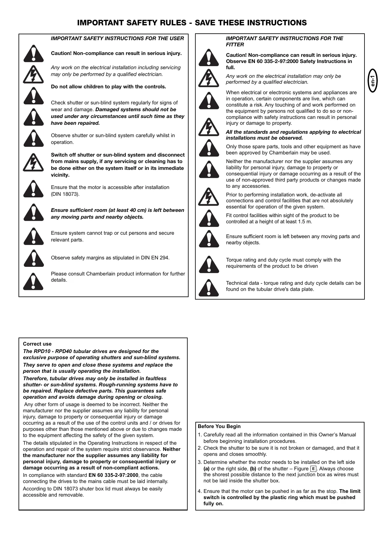
| IMPORTANT SAFETY INSTRUCTIONS FOR THE USER | |
| Caution! Non-compliance can result in serious injury. | |
| Any work on the electrical installation including servicing may only be performed by a qualified electrician. | |
| Do not allow children to play with the controls. | |
| Check shutter or sun-blind system regularly for signs of wear and damage. Damaged systems should not be used under any circumstances until such time as they have been repaired. | |
| Observe shutter or sun-blind system carefully whilst in operation. | |
| Switch off shutter or sun-blind system and disconnect from mains supply, if any servicing or cleaning has to be done either on the system itself or in its immediate vicinity. | |
| Ensure that the motor is accessible after installation (DIN 18073). | |
| Ensure sufficient room (at least 40 cm) is left between any moving parts and nearby objects. | |
| Ensure system cannot trap or cut persons and secure relevant parts. | |
| Observe safety margins as stipulated in DIN EN 294. | |
| Please consult Chamberlain product information for further details. |
| IMPORTANT SAFETY INSTRUCTIONS FOR THE FITTER Caution! Non-compliance can result in serious injury. Observe EN 60 335-2-97:2000 Safety Instructions in full. Any work on the electrical installation may only be performed by a qualified electrician. When electrical or electronic systems and appliances are in operation, certain components are live, which can constitute a risk. Any touching of and work performed on the equipment by persons not qualified to do so or non-compliance with safety instructions can result in personal injury or damage to property. All the standards and regulations applying to electrical installations must be observed. Only those spare parts, tools and other equipment as have been approved by Chamberlain may be used. Neither the manufacturer nor the supplier assumes any liability for personal injury, damage to property or consequential injury or damage occurring as a result of the use of non-approved third party products or changes made to any accessories. Prior to performing installation work, de-activate all connections and control facilities that are not absolutely essential for operation of the given system. Fit control facilities within sight of the product to be controlled at a height of at least 1.5 m. Ensure sufficient room is left between any moving parts and nearby objects. Torque rating and duty cycle must comply with the requirements of the product to be driven Technical data - torque rating and duty cycle details can be found on the tubular drive's data plate. |
Correct use
The RPD10 - RPD40 tubular drives are designed for the exclusive purpose of operating shutters and sun-blind systems.
They serve to open and close these systems and replace the person that is usually operating the installation.
Therefore, tubular drives may only be installed in faultless shutter- or sun-blind systems. Rough-running systems have to be repaired. Replace defective parts. This guarantees safe operation and avoids damage during opening or closing.
Any other form of usage is deemed to be incorrect. Neither the manufacturer nor the supplier assumes any liability for personal injury, damage to property or consequential injury or damage occurring as a result of the use of the control units and / or drives for purposes other than those mentioned above or due to changes made to the equipment affecting the safety of the given system.
The details stipulated in the Operating Instructions in respect of the operation and repair of the system require strict observance. Neither the manufacturer nor the supplier assumes any liability for personal injury, damage to property or consequential injury or damage occurring as a result of non-compliant actions.
In compliance with standard EN 60 335-2-97:2000, the cable connecting the drives to the mains cable must be laid internally.
According to DIN 18073 shutter box lid must always be easily accessible and removable.
Before You Begin
- Carefully read all the information contained in this Owner's Manual before beginning installation procedures.
- Check the shutter to be sure it is not broken or damaged, and that it opens and closes smoothly.
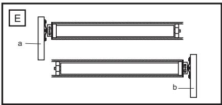
- Determine whether the motor needs to be installed on the left side (a) or the right side, (b) of the shutter – Figure E. Always choose the shostest possible distance to the next junction box as wires must not be laid inside the shutter box.
- Ensure that the motor can be pushed in as far as the stop. The limit switch is controlled by the plastic ring which must be pushed fully on.
Performance features
| Model | Diameter | Torque | Speed | Operating Voltage | Frequency | Current input | Motor Rating | Operating time | Limit Switch Range |
| (mm) | (Nm) | (rpm) | (V) | (Hz) | (A) | (W) | (min) | (revolution) | |
| RPD10 | 35 | 10 | 17 | 230 | 50 | 0,53 | 121 | 4 | 39 |
| RPD15 | 45 | 15 | 15 | 230 | 50 | 0,60 | 133 | 4 | 25 |
| RPD25 | 45 | 25 | 15 | 230 | 50 | 0,89 | 191 | 4 | 25 |
| RPD40 | 45 | 40 | 15 | 230 | 50 | 0,77 | 170 | 4 | 25 |
Max. area (area = length x breadth)
| RPD10 | RPD15 | RPD25 | RPD40 | |
| PVC | 5m² | 7,5m² | 11m² | 16m² |
| ALU | 4m² | 6m² | 9m² | 12m² |
| WOOD | 2m² | 3m² | 5m² | 7m² |
| AWNING | 20m² |
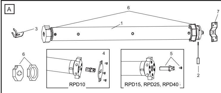
Carton Contents
- Motor (1)
- Adjuster pin (2)
- Drive adapter safety catch (3)
- Square pin (RPD10) (4)
- Square pin (RPD15 - RPD40) (5)
- Shaft adapter (6)
-
Wall bracket (7)
-
Manual
INSTALLATION
Rough- in or install conduit pipe to the connector box for the electrical connecting line according to local building and electrical codes.
THE DRIVE IS PREMOUNTED. THE DESCRIPTION IS FOR CHECKING PURPOSES!

Place the tube drive adapter (6) on the motor and fix the drive adapter with the parts (3).
Fix the square pin with the screws on the motor (4 or 5).

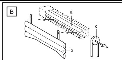
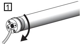
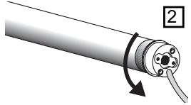
Fully unroll the shutter (a). Remove the shutter material from the tube (b). Remove the manual control (c).

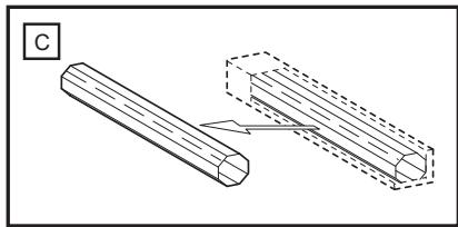
Remove the tube.

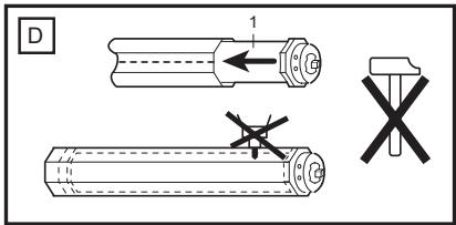
Push the motor (1) completely into the tube. The limit switch operates only if the drive unit is fully inserted. Ensure that the adapter ring is pushed fully home. Do not force it or strike it.
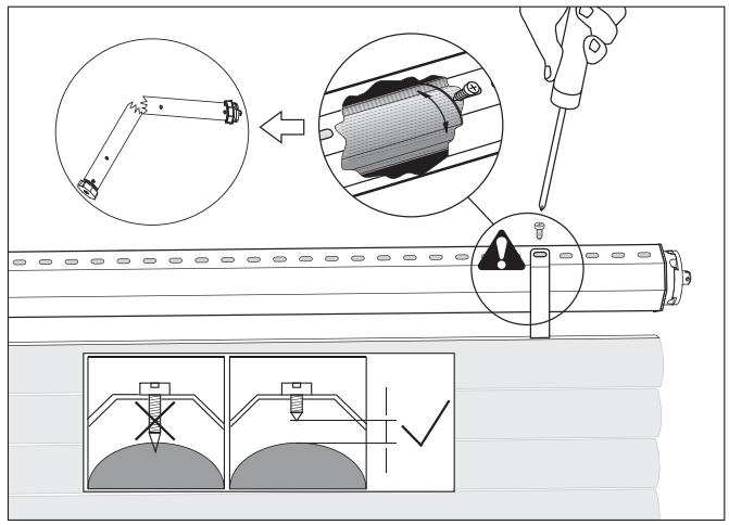
Do not damage the tubular motor by drilling!

Proceed according to the specific requirements for left-sided (a) or right-sided (b) operation:

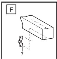
Secure the mounting bracket (7) to the wall (use suitable screws and plugs).

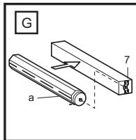
Insert the motor (a) into the mounting bracket (7) and secure it.
Make sure the set screws for the limit adjustments are accessible.
Don't return the shutter material to the tube yet!

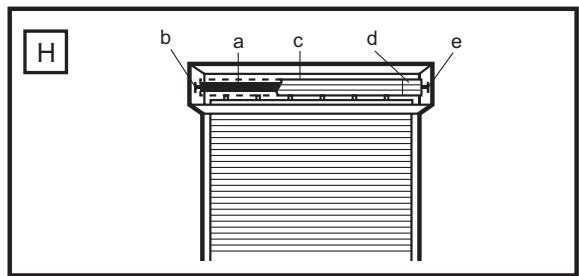
Correct Installation
The illustration H also shows the wall bracket on the drive side (b), the motor (a); the steel tube (c); the end cap (d); and the opposite wall bearing (e).

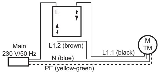
ELECTRICAL CONNECTION

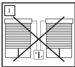
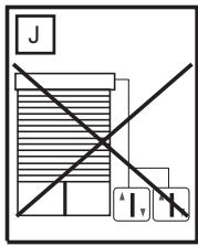
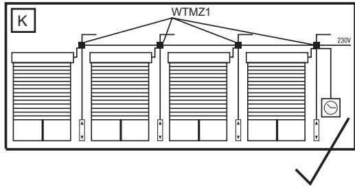
Never connect more than one motor to a timer or wall switch without using a central module - (available as an accessory), i.e. one central module is required for each connected motor.
For a left-side motor installation, follow the wiring diagram exactly as shown in the control accessory package.
For the correct direction of rotation in a right-side motor installation, electrical wires (brown & black) must be reversed between the control accessory and the motor. (See instructions packed with the accessory you have chosen).
Have the electrical hook-up done by a qualified electrician in compliance with your local electrical code.


SETTING THE LIMITS
"Open" and "Close" Positions
In general the following applies:
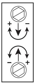
- = Stops later
- = Stops earlier
1 White screw
2 Red screw
My roller shutter box is:
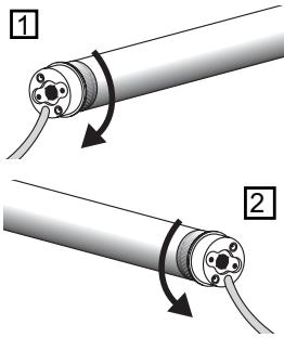
A: A left-handed installation. I look into the box and the limit switch of the motor is on the left (see Fig. L1)
White = Limit switch AT BOTTOM
Red = Limit switch AT TOP
B: A right-handed installation. I look into the box and the limit switch of the motor is on the right (see Fig. L2)
Red = Limit switch AT BOTTOM
White = Limit switch AT TOP
The bottom adjusting screw is always for the upper limit and the upper is always for the lower limit, no matter whether the motor is pushed into the shaft from the right or the left.
PLEASE READ THROUGH AND NOTE THE FOLLOWING INSTRUCTIONS ACCURATELY BEFORE SETTING THE END POSITIONS.
Connect a suitable switch to the roller shutters. Run the roller shutter drive downwards until it switches itself off and then (and only then) attach the roller shutter jacket to the shaft.
Advice: In order to fix the roller shutter hangers to the shaft, ONLY use short fixing screws. If the screws are too long damage may occur to the motor. The recommended fixing method for the hangers is without screws by means of spring band loops (which are hooked on). Allow drive to run upwards. If it switches off too early the bottom adjusting screw must be adjusted in the plus direction. Each full turn of this screw extends the travel path by about 40^ of one turn of the motor. The motor should stop just a few inches below the window frame. If not the adjusting screw should be adjusted in the minus direction. After this the drive must be driven back a little and then up again to check the result.
It is possible that the drive will switch itself off after several trips because it has reached a temperature which is too high. However after 15 - 20 minutes cooling time it will be ready to operate again. Please note that the limit switches of the drive only function properly if the drive has been installed correctly and is completely within the shaft.
Advice: In order to fix the roller shutter hangers to the shaft, ONLY use short fixing screws. If the screws are too long damage may occur to the motor. The recommended fixing method for the hangers is without screws by means of spring band loops (which are hooked on).

Connection of Model TCS1ED
FAQs AND REMEDIES
The drive will not operate:
- Check the domestic fuses and power supply
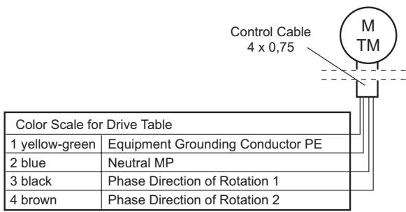
- Has the motor been connected correctly? Check that N L L have been correctly connected.
- The limit switches have already been adjusted and both limit switches turned to the minimum. Turn both limit switches by several turns in the plus direction and test again.
- The motor became too hot and cut out. Try again after about 30 minutes cooling time.
The drive will only run in one direction:
- The drive is already at the limit switch. Adjust the limit switch or travel the motor in the other direction for several seconds so that it can travel away from the limit switch.
- Install drive. The limit switch can only function in this way.
The drive cannot find the limit switch:
- The drive is not installed. Because of this the limit switch will not turn.
- The limit switch is wrongly set. Remove the hanger and travel the motor downwards until it switches off. Then turn the limit switch for OPEN for a long time in the minus direction. Keep testing in the meantime. Then start the setting work again.
- The adapter ring on the motor, which actuates the limit switch, does not turn or is not mounted.
- Run installed motor without hanger downwards until it switches off. By briefly running upwards check whether the motor didn't possibly need a cooling break and had therefore switched itself off.
The drive is noisy and will not run:
- The clutch drive ring on the end of the motor has come off or was not plugged on.
- The motor will not turn because the roller shutter is jammed.
- The motor is not getting sufficient power because of a poor feed cable.
- Another motor is attached to the same switch. Not permitted! Only operate one switch with one motor or use an isolating relay (accessory).
- Remove locks, handles or stoppers on the roller shutter.
The domestic fuse was tripped:
- The fuse was overloaded due to the operation of several motors with isolating relays. It is necessary to have the domestic electrical system modified by a specialist.
- Incorrectly connected switch which has caused a short-circuit.
- Isolating relay incorrectly connected (only relevant if several motors are used with one switch).
- Two switches have been operated with one motor and the switches were depressed differently. Not permitted! Use isolating relay (accessory).
The drive is noisy:
- Close the roller shutter box.
- The drive has too much axial play (shaft). The roller shutter hanger or the shaft bearing is in poor condition and causes the noise. It is
necessary to change the guide rails or the fixing on the shaft.
- Wall bracket is faulty. Special rubber dampers for wall brackets can be obtained from your specialist dealer.
The drive does not unwind neatly from the open position:
- The UP end position is too high. Set the roller shutter jacket 3-5 cm lower.
- The run-in taper at the upper end of the guide rail is not present or is bent.
- The end position of the roller shutter has changed and is higher than it should be because the jacket winds shorter
- The guide rails are defective, they possibly require lubrication.
Notes:


BELANGRIJKE VEILIGHEIDSINSTRUCTIES VOOR DE GEBRUKER
CORRECTE INSTALLATIE
-
= stop later
-
= stopt vroeger
1 Witte schroef
2 Rode schroef
Chamberlain GmbH warrants to the first retail purchaser of this product that the product shall be free from any defect in materials and/or workmanship for a period of 24 full months (2 years) from the date of purchase for RPD10 - RPD40 Series Models. Upon receipt of the product, the first retail purchaser is under obligation to check the product for any visible defects.
Conditions: The warranty is strictly limited to the reparation or replacement of the parts of this product which are found to be defective and does not cover the costs or risks of transportation of the defective parts or products.
This warranty does not cover non-defect damage caused by unreasonable use (including use not in complete accordance with Chamberlain's instructions for installation, operation and care; failure to provide necessary maintenance and adjustment; or any adaptations of or alterations to the products), labor charges for dismantling or reinstalling of a repaired or replaced unit or replacement batteries.
A product under warranty which is determined to be defective in materials and/or workmanship will be repaired or replaced (at Chamberlain's option) at no cost to the owner for the repair and/or replacement parts and/or product. Defective parts will be repaired or replaced with new or factory rebuilt parts at Chamberlain's option. If, during the warranty period, the product appears as though it may be defective, contact your original place of purchase.
This warranty does not affect the purchaser's statutory rights under applicable national legislation in force nor the purchaser's rights against the retailer arising from their sales purchase contract. In the absence of applicable national or EC legislation, this warranty will be the purchaser's sole and exclusive remedy, and neither Chamberlain GmbH nor its affiliates or distributors shall be liable for any incidental or consequential damages for any express or implied warranty relating to this product.
No representative or person is authorized to assume for Chamberlain GmbH any other liability in connection with the sale of this product.