SUB300 - Gate automation CHAMBERLAIN - Free user manual and instructions
Find the device manual for free SUB300 CHAMBERLAIN in PDF.
User questions about SUB300 CHAMBERLAIN
0 question about this device. Answer the ones you know or ask your own.
Ask a new question about this device
Download the instructions for your Gate automation in PDF format for free! Find your manual SUB300 - CHAMBERLAIN and take your electronic device back in hand. On this page are published all the documents necessary for the use of your device. SUB300 by CHAMBERLAIN.
USER MANUAL SUB300 CHAMBERLAIN
Apricancello interrato

Für Service: (49) 6838/907-172

Pour Service: 03-87-98-15-93

For Service: (+44) 0845-602-4285

SUB100S arm for SUB-series underground drives
Purpose of usage
The SUB100S adapter arm is used in conjunction with swing gates, in the case of which classic installation procedures are not possible. In classic installation contexts, the pivotal point of the gate is the same as the pivotal point of the motor arm. This is very easy if the gate post is fitted at the same time as the drive; retrofitting at a later date is, however, very difficult. Either the dimensional stability is not assured or the box cannot be shifted close enough to the post.
The SUB100S arm allows the pivotal points to be offset by up to 5cm in all directions around the pivotal point concerned.

The maximum offset distance between the pivotal points is limited to 5cm as otherwise an extremely dangerous scissor movement between the arm and the gate may occur.
Installation
The arm is welded to the SUB110 or SUB180 arm with the runner roller pointing upwards.
The runner roller runs in the U-rail and compensates for the pivotal point offset (max. 5cm).
Installation on a wooden gate is problematical. In such cases, the U-rail needs to be extended so that it can be better screwed in place and does not loosen in the wood.
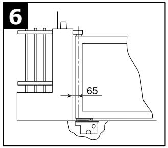
Installation in cases where the space between the gate and driveway is less than 6cm
The U-rail is welded to the inside of the gate frame.
The lid of the drive box needs to be located at the same height as the driveway or higher. The arm no longer fits through underneath the gate. The pivotal point has to be offset on the inside of the gate.
Installation where the space between gate/door and driveway is between 6cm and approx. 12cm
The U-rail is welded to the inside of the gate frame.
Installation where the space between the gate and driveway is more than 12cm
The difference between this option and the others is that the U-rail has to be fitted directly underneath on to the gate frame. If the space is extremely large, the level has to be balanced out by putting something (flat steel bar) underneath between the motor arm and the SUB100S arm. The underground drive ought generally to be installed as close to the pivotal point as possible.
The runner roller and the rail need to be greased.

SUB-110 (110° Grad Arm, Standardarm)
ACCESSIONS EN OPTION 11
√73/23/EEC
1999/5/EC
Manager, Regulatory Affairs
THE CHAMBERLAIN GROUP, INC.
January, 2005

Babba P. Keckhoo
Start by Reading These Important Safety Rules

These safety alert symbols mean Caution - a personal safety or property damage instruction. Read these instructions carefully.
This gate opener is designed and tested to offer reasonable safe service provided it is installed and operated in strict accordance with the following safety rules.
Failure to comply with the following instructions may result in serious personal injury or property damage.
IMPORTANT INSTRUCTIONS FOR SAFER MOUNTING


Keep gate balanced. Sticking or binding gates must be repaired. Do not attempt to repair the gates yourself. Call for service.
Handle tools and hardware carefully and do not wear rings, watches or loose clothing while installing or servicing a gate opener.
Installation and wiring must be in compliance with your local building and electrical codes. Connect the power cord only to properly earthed mains.

Ensure that persons who install, maintain or operate the gate opener follow these instructions.

After installation you must check that the mechanism is correctly adjusted and that the drive, the safety system and the hand-held transmitter if provided, function correctly.

The driven component can move in an uncontrolled way, e.g. due to mechanical failure, when the transmitter is operated.
CAUTION: INCORRECT MOUNTING CAN LEAD TO SERIOUS INJURIES

Disengage all existing gate locks to avoid damage to gate opener.
Disconnect electric power to the gate opener before making repairs.

Keep additional accessories out of the reach of children. Do not allow children to operate push button(s) or remote control(s). Serious personal injury from a closing gate may result from misuse of the opener.

In the case of drives, which are controlled from a switch unit with a preset OFF, it is essential that the control terminal is fitted within the direct visual range of the driven component, but is at a suitable distance from moving parts and at a minimum height of 1.5m .
Note: The minimum height of 1.5m does not apply to control terminals with a preset OFF, which are controlled by a key or similar.
Keep this manual where it can be readily referenced during maintenance.

When operating a controller with a preset OFF position, always make sure that other people are kept away from the device.
Contents:
Safety Rules: Page 1
Technical data: Page 1
Warranty: Page 1
Contents of the carton: Page 2
Before you begin: Page 2
Installation of the unit: Page 2, Figure 1 - 9
Electrical connections: Page 2, Figure 1
Safety: Page 3
Check on operation: Page 3
Final remarks: Page 3
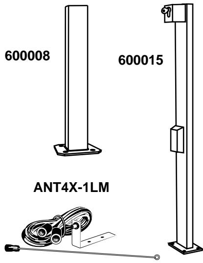
Accessories: Page 3, Figure 11
TECHNICAL DATA
| Nominal voltage | VAC | 230V-240 |
| Frequency | Hz | 50 |
| Nominal power | W | 300 |
| Max. power consumed | W | 350 |
| Nominal current | A | 2,1 |
| Nominal tractive force | N | 380 |
| Capacitor | micro F | 10 |
| Thermal overload protection | °C | 150° |
| Motor speed | rpm | 1400 |
| Cycles (full load) | cycles/h | 20 |
| Operating temperature | °C | -25/+75 |
| Protection class | I | |
| Degree of protection | IP | 67 |
| Weight (only motor) | kg | 10 |
| Controller | optional | |
| Transmitter | optional | |
| Radio frequency | optional | |
| Infrared Sensor | optional | |
| Signal lamp | optional | |
| Key switch | optional | |
| Antenna | optional | |
| Maximum wing length | 4m | |
| Max. wing weight | 600kg/2,5r |
WARRANTY
Chamberlain GmbH warrants to the first retail purchaser of this product that the product shall be free from any defect in materials and/or workmanship for a period of 24 full months (2 years) from the date of purchase for the Wing Gate Openers. Upon receipt of the product, the first retail purchaser is under obligation to check the product for any visible defects.
Conditions: The warranty is strictly limited to the reparation or replacement of the parts of this product which are found to be defective and does not cover the costs or risks of transportation of the defective parts or product.
This warranty does not cover non-defect damage caused by unreasonable use (including use not in complete accordance with Chamberlain's instructions for installation, operation and care; failure to provide necessary maintenance and adjustment, or any adaptations of or alterations to the products), labor charges for dismantling or reinstalling of a repaired or replaced unit or replacement batteries.
A product under warranty which is determined to be defective in materials and/or workmanship will be repaired or replaced (at Chamberlain's option) at no cost to the owner for the repair and/or replacement parts and/or product. Defective parts will be repaired or replaced with new or factory rebuilt parts at Chamberlain's option.
This warranty does not affect the purchaser's statutory rights under applicable national legislation in force nor the purchaser's rights against the retailer arising from their sales/purchase contract. In the absence of applicable national or EC legislation, this warranty will be the purchaser's sole and exclusive remedy and neither Chamberlain GmbH nor its affiliates or distributors shall be liable for any incidental or consequential damages for any express or implied warranty relating to this product.
No representative or person is authorized to assume for Chamberlain GmbH any other liability in connection with the sale of this product.
PACKAGE CONTENTS
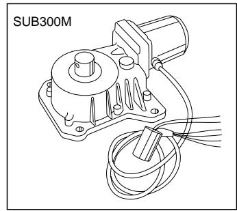
SUB300M (motor)
- Motor incl. connecting cable
- Capacitor
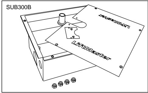
SUB300B (box)
- Box (1x)
- Lid for box (1x)
- Front plate for box (1x)
- Bolts for lid (4x)
- Nuts for motor (4x)
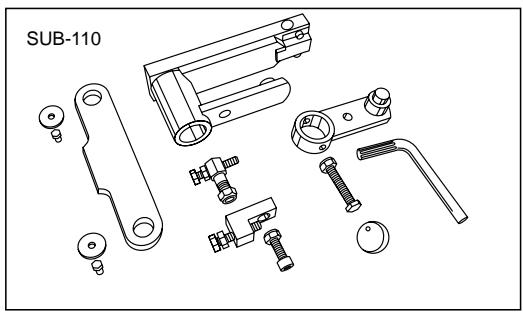
SUB-110 ( 110^o arm, standard arm)
- Drive arm 110^ (1x)
- Motor arm 110^ (1x)
- Bolt for motor arm (1x)
- Nut for motor arm (1x)
Interlock deactivating key (1x) - Bearing ball (1x)
- End stop - box OPEN (1x)
- End stop CLOSED (1x)
- Connecting arm
- Connecting arm bolts (2x)
- Connecting arm washers (2x)
SUB-180 (180° arm)
Opens gate up to 180 degrees
SUB-100S (1000 arm with rails)
Available from mid 2005. Can be used if the box cannot be installed so that the pivot points are below one another.
BEFORE YOU BEGIN

Planning and precision are vital for the mounting of an underground opener, in order to ensure that unforeseen circumstances do not
limit or prevent proper operation later.
Adequate drainage facilities are essential to avoid malfunction.
Size of gate: The size of the gate is one very important factor.
Wind can slow the gate down or distort it, causing a marked increase in the force required to move it.
Weight of gate: The specified weight of the gate only gives a rough indication of the output required from the drive. The function which the gate is expected to perform is also important in this connection.
Temperature: Low outdoor temperatures can make it more difficult or impossible to set the gate into motion (e.g. because of soil changes).
High outdoor temperatures may cause the temperature cutoff (at about 135^ ) to be triggered earlier.
Operating frequency/duty factor: The drives have a maximum duty factor of around 30 - 50% (e.g. 50% of one hour). This factor depends heavily on many influencing factors. The drive is not suitable for systems with a high cycling rate (continuous operation) and such use would mean that the guarantee becomes invalid.
PREPARATIONS
Before installation, please check contents of packaging.
Please remember that you will require some additional material not included in the assembly kit delivered, such as empty piping, cables, screws, plugs, etc. In order to avoid undesirable oscillation, the wing should be stable and the hinges should have as little play as possible. The more easily the gate moves, the finer should the force adjustment be made. Low-rigidity wooden gates should be reinforced with a metal frame.
INSTALLATION OF THE UNIT 1 - 9
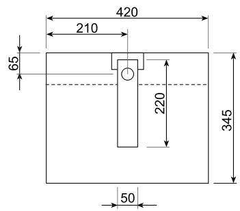
- The pivot point of the gate can be found on the mounting box = pivotal point of the arm (SUB 110 and SUB 180) (figure 5-8).
SUB 110 opens gates up to 110^ . Mount the arm which will later be welded to the gate and don't forget the bearing ball. For details see also under assembly and adjustment (figure 2-4).
SUB 180 opens gates by up to 180^ . A detailed description of the assembly is included with the SUB 180 arm.
SUB 100S is a special arm with rails with which the drive does not have to be positioned directly beneath the pivot point. This is ideal for retrofitting or for special pillar situations (max. 300kg / 3m ). A detailed description of the assembly is included with the SUB 100S arm. Available mid 2005.
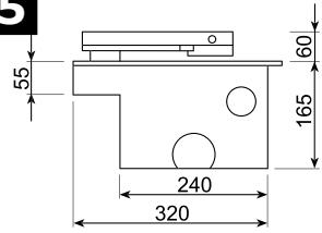
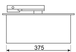
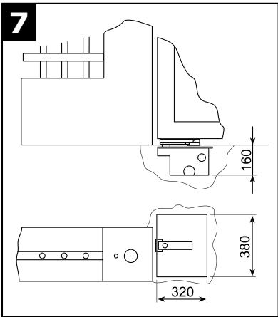
- Check the overall dimensions to ensure that you will have enough room to dig out a hole for the motor housing. The opening angle of the gate has an important influence on the position of the motor housing (figures 5-7).
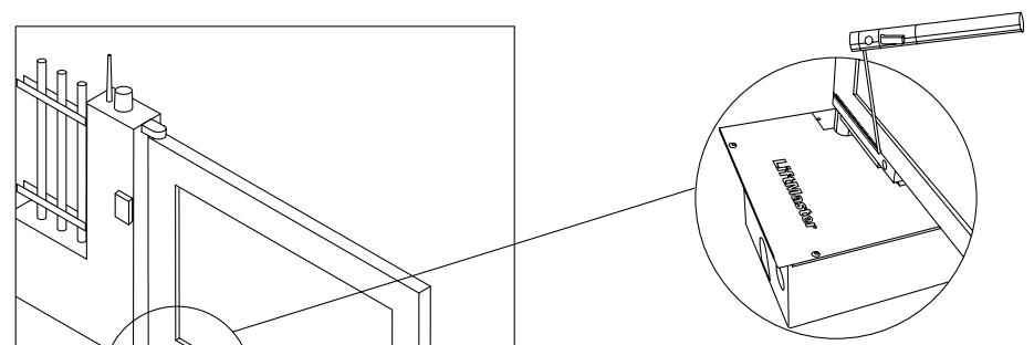
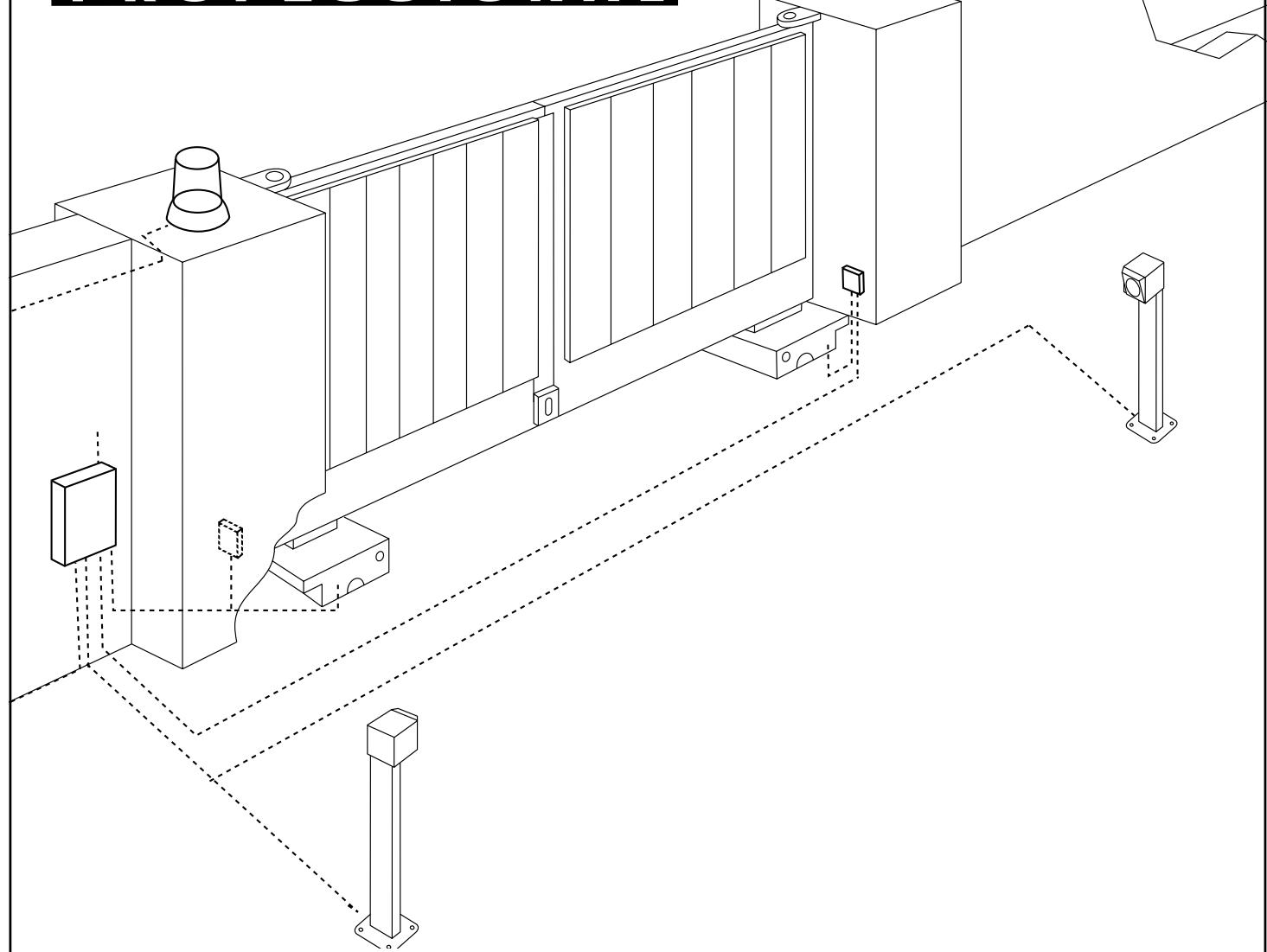
The motor housing must be set in concrete. The piping for the electrical wiring and the drainage should be borne in mind in this connection (figure 1). Remember that the final dimensions of the installation (including plaster layer etc.) determine the room available. The top of the motor housing should be slightly higher than the concrete surrounding it.
The concrete takes a couple of days to set completely. You should aim at a strength rating of at least MG2a according to DIN standards (normal strength).
- Once the motor housing has been set in place, the gate can be mounted on top of it. Additional hinges will certainly be needed to ensure proper guidance.
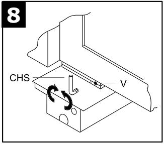
- The arm with the facilities for switching to manual operation must be welded on to the gate. Turning the special key in the hole provided for it switches the system to manual operation so that the gate can be opened by hand if necessary (figures 1, 4 and 8).
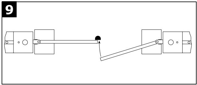
- Stops must be mounted on the floor to limit the limit the motion of the gate (figure 9).
- After all assembly work has been completed, it is advisable to protect the motor housing against seepage of water with the aid of a layer of silicone sealant.
Tip:
If the gate is delivered at the same time as the drive (no retrofitting), you should proceed as follows:
The box should be welded onto the gate pillar first before installation. This ensures that the pivot points and spacings cannot become displaced. The box is assembled with the pillar.
Caution: During installation there is a risk to becoming trapped between the driven component and the surrounding parts of the building (e.g. a wall) due to the opening movement of the driven component.
TIPS FOR DRAINAGE A and B
If the drainage of the installation cannot be connected up to the main drains, it may be possible to make use of a drainage pit. The floor must be permeable to water, and the cover of the motor housing should be protected against heavy rainfall or surface water with silicone sealant. The drainage pit should be dug out so as to be appreciably lower than the bottom of the motor housing, and its capacity should exceed that of the motor housing. The pit should be filled with coarse rubble or gravel, and should be tiled to keep out sediment and water from the top and sides. Facilities should be provided to lead any water getting into the motor housing to this drainage pit.
ASSEMBLY OF THE SUB-110 ARM
We will assume here that the arm is already mounted and the bearing ball (greased) is in its proper location.
TIP: Many parts have extremely small fitting tolerances in order to ensure long, continuous operation. Some strength will be needed to mount the parts. A PVC hammer and good tools are essential.
- Plug the short motor arm onto the motor and fix it with bolt and nut (figure 2).
- Mount the gate CLOSED end stop. Don't completely tighten the bolts yet so that the gate can still move (figure 2).
- Mount the gate OPEN end stop. Don't tighten the bolts to 100% yet but allow some movement (figure 4A).
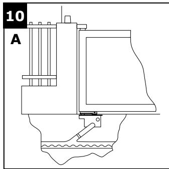
- Place motor in box. The motor shaft should point outwards in the entrance. Install motor power cable and lead it upwards and out of the box to the distribution box. Do not distribute power in this box; moisture! (figure 10A&B).
- Tighten motor with the four bolts (figure 3).
- Position connecting arm, secure with bolts and washers. In the connecting arm are plain bronze bearings with very tight fits (figure 4A).
Setting of the end stops:
The stops cannot be set until the motor has been connected to the power supply. If the settings are made without the controller the motor can be directly connected to 230V. For this purpose the capacitor must also be connected (see electrical connection).
Caution: The motor is very powerful and can cause damage to the box and the gate system if it is not switched off at the correct time.
- Close the gate as far as the required position or to the floor stop. Turn the end stop so that the bolt and the fitting meet the connecting arm accurately. Set with the nut and then tighten ALL parts (figure 4A).
- Open the gate as far as the required position or to the floor stop. Turn the end stop so that the connecting arm is accurately met at right angles (90^) . Set with the nut and then tighten ALL parts (figure 4A).
ELECTRICAL CONNECTIONS 1
We recommend the use of the CB1, GOC1A or CB11 (available mid 2005) controllers. The controllers are configured for different requirements. Please make contact with your LiftMaster dealer. If you buy a kit a controller will be included.
The coding of the connection terminals is as follows:
N=neutral(blue)
L1= black - On or Off (change over if necessary)
L1= brown - On or Off (change over if necessary)
Do not forget to earth the system!
The capacitor must be connected between L1 and L2 (black and brown wires) in the control circuit, and must be protected against water.
CHECK ON OPERATION
Activate the function "Automatic close" on the control unit. If the gate opens automatically after the preset time, exchange the brown and black leads. Most control units have a time function. This should always be set to about 3 - 5 seconds more than the time actually required. The preliminary setting should be made somewhat more than this, to allow a safety margin; after the necessary adjustments to the system have been made, the time can be set more accurately. NB: The drive works more slowly under windy conditions.
SAFETY MEASURES

An automatically operated wing gate should always be further protected with the aid of flashing lights, contact strips and photoelectric barriers. In any case, take care to comply with the relevant
standards and regulations.
FINAL REMARKS
Arrange the handover of the wing gate opener with your customer Make sure that persons will operate the gate are familiar with its functions and can operate them without problems. Have your customer practice operating the gate until they are fully acquainted with all the following:
- Main switch.
- Rules of operation (e.g. do not drive through while the gate is still opening).
- Additional safety features (photoelectric barrier, contact strip, flashing lights, etc.).
- Switch to manual operation in case of power failure.
- Provide the customer with a full set of instructions. Inform him to keep them in a safe place and read them when possible.
- Reference a checklist, so that you have a record of which functions have been explained and of any points not dealt with.
OPTIONAL ACCESSORIES 11
See also the LiftMaster product catalogue:
Gate Opener Catalog
Declaration of Conformity
The undersigned, hereby declare that the equipment specified, and all accessories, conforms to the Directives and Standards stated.
Model: .SUB300M EN55014, EN61000-3, EN61000-4, ETS 300 683, EN 300 220-3, EN60335-1, and EN60335-2-103
√89/336/EEC
73/23/EEC
√1999/5/EC
Declaration of Incorporation
A power door operator, in combination with a door must be installed and maintained according to all the Manufacturer's instructions, to meet the provisions of Machinery Directive, 89/392/EEC.
B.P.Kelkhoff
Manager, Regulatory Affairs
THE CHAMBERLAIN GROUP, INC.
January, 2005

Babasa P. Keckhoff
LEES EERST DEZE BELANGRIJKE VEILIGHEIDSVOORSCHRIFTEN

SUB-110 (1100-arm, standardarm)
SUB-100S (100°-arm met rails)
√ 89/336/EEC
73/23/EEC
√1999/5/EC
Inbouwverklaring
Manager, Regulatory Affairs
THE CHAMBERLAIN GROUP, INC.
January, 2005

Barbarea P. Keelkhoff
LEGGERE INNANZITUTTO QUESTE IMPORTANTI NORME DI SICUREZZA


√89/336/EEC
73/23/EEC
√1999/5/EC
Manager, Regulatory Affairs
THE CHAMBERLAIN GROUP, INC. January, 2005

Babbaa Pekkho
5

11
FLA24-2 (CB11)
FLA230-2 (CB1)
94335E (433MHz)
9747E (433MHz)
CHAMBERLAIN
LiftMaster ™
PROFESSIONAL

Anleitungen
Unterflurantrieb

Instructions
Apricancello interrato

Für Service: (49) 6838/907-172

Pour Service: 03-87-98-15-93

For Service: (+44) 0845-602-4285

SUB 180 (180 degree arm)
- Drive arm, 180^ (1x)
- Motor-wheel chain, 180^ (1x)
- Bolt, motor arm (1x)
- Nut, motor arm
- Interlock deactivating key (1x)
- Bearing ball (1x)
- Chain (1x)
- Chain joint (1x)
ASSEMBLY with SUB300M, SUB300B
It is assumed here that the 180^ arm is already mounted and the bearing ball (greased) is in its place.
TIP: Many parts have extremely tight fitting tolerances to guarantee long, continuous operation. Often some strength is required to mount the parts. A PVC hammer and good tools are an essential prerequisite.
- Put on the chain wheel. Fix it with the bolts and nuts (figure 2).
- Place motor in the box. Install motor power cable and lead it upwards out of the box to the dividing box. Do not distribute power in this box; moisture! (figure 3).
These instructions describe the assembly between the drive arm SUB-180, SUB300M, SUB300B.

Safety and warning information must be taken from the SUB300B instructions and followed.
Caution: During installation there is a risk of becoming trapped between the driven component and the surrounding parts of the building (e.g. a wall) due to the opening movement of the driven component.
- Tighten motor with the four bolts (figure 3).
- Place chain on gears and secure with chain joint (figure 4).
Setting
The 180^ gearing has no stopping devices in the box. It is extremely important that floor stops are provided for the gate. These must be solidly installed.

SUB-180 (180-grade-arm)
- Openerarm 180^ (1x)
- Motortandwielketting 180^ (1x)
- Schroef motorarm (1x)
Moer motorarm (1x) - Ontgrendelingssleutel (1x)
Lagerkogel (1x) - Ketting (1x)
- Kettingslot (1x)