
ZERO4 - Mixer KORG - Free user manual and instructions
Find the device manual for free ZERO4 KORG in PDF.
| Product type | 4-channel digital mixer |
| Brand | KORG |
| Model | ZERO4 |
| Power supply | local mains, 32 W |
| Sampling frequencies | 44.1 kHz, 48 kHz, 96 kHz, 192 kHz |
| A/D conversion | 24-bit, 64-times oversampling |
| D/A conversion | 24-bit, 128-times oversampling |
| FireWire interface | Audio/MIDI, up to 8 inputs and 16 audio outputs |
| Equalizer | 11 types (EQ, isolator, filter) |
| Channel effects | 8 types (LFO LPF, LFO HPF, Phaser, Flanger, Slicer, Pitch Shift, Delay, Tape Echo) |
| Master effect | 10 types (LPF, HPF, Jet, Decimator, Phaser, Flanger, Auto Pan, Reverb, Delay, Tape Echo) |
| Loop sampler | Loop Play and Gate Play, length adjustable according to BPM |
| BPM detection | Auto BPM, Tap Tempo, manual setting |
| Analog inputs | MIC (XLR/TRS), GUITAR (TS), LINE (TRS), CD/LINE (RCA), PHONO (RCA) |
| Analog outputs | MASTER OUT (XLR), BOOTH OUT (TRS), REC OUT (RCA), headphone (6.35 mm jack and mini jack) |
| Digital output | Coaxial S/PDIF |
| MIDI | 5-pin DIN input and output |
| Maintenance and cleaning | Clean with a soft, dry cloth |
| Safety | Do not expose to moisture, do not block vents, use a grounded outlet |
| Included accessories | Power cord, user manual, CD-ROM |
Frequently Asked Questions - ZERO4 KORG
User questions about ZERO4 KORG
0 question about this device. Answer the ones you know or ask your own.
Ask a new question about this device
Download the instructions for your Mixer in PDF format for free! Find your manual ZERO4 - KORG and take your electronic device back in hand. On this page are published all the documents necessary for the use of your device. ZERO4 by KORG.
USER MANUAL ZERO4 KORG
IMPORTANT SAFETY INSTRUCTIONS
- Read these instructions.
- Keep these instructions.
- Heed all warnings.
- Follow all instructions.
- Do not use this apparatus near water.
- Mains powered apparatus shall not be exposed to dripping or splashing and that no objects filled with liquids, such as vases, shall be placed on the apparatus.
- Clean only with dry cloth.
- Do not block any ventilation openings. Install in accordance with the manufacturer's instructions.
- Do not install near any heat sources such as radiators, heat registers, stoves, or other apparatus (including amplifiers) that produce heat.
- Do not defeat the safety purpose of the polarized or grounding-type plug. A polarized plug has two blades with one wider than the other. A grounding type plug has two blades and a third grounding prong. The wide blade or the third prong are provided for your safety. If the provided plug does not fit into your outlet, consult an electrician for replacement of the obsolete outlet. (for U.S.A. and Canada)
- Protect the power cord from being walked on or pinched particularly at plugs, convenience receptacles, and the point where they exit from the apparatus.
- Only use attachments/accessories specified by the manufacturer.
- Unplug this apparatus during lightning storms or when unused for long periods of time.
- Turning off the power switch does not completely isolate this product from the power line so remove the plug from the socket if not using it for extended periods of time.
- Install this product near the wall socket and keep the power plug easily accessible.
- WARNING—This apparatus shall be connected to a mains socket outlet with a protective earthing connection.
-
Refer all servicing to qualified service personnel. Servicing is required when the apparatus has been damaged in any way, such as power-supply cord or plug is damaged, liquid has been spilled or objects have fallen into the apparatus, the apparatus has been exposed to rain or moisture, does not operate normally, or has been dropped.
-
Do not install this equipment on the far position from wall outlet and/or convenience receptacle.
- Do not install this equipment in a confined space such as a box for the conveyance or similar unit.
- Use only with the cart, stand, tripod, bracket, or table specified by the manufacturer, or sold with the apparatus. When a cart is used, use caution when moving the cart/apparatus combination to avoid injury from tip-over.

WARNING:
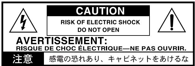
TO REDUCE THE RISK OF FIRE OR ELECTRIC SHOCK DO NOT EXPOSE THIS PRODUCT TO RAIN OR MOISTURE.
The lightning flash with arrowhead symbol within an equilateral triangle, is intended to alert the user to the presence of uninsulated “dangerous voltage” within the product's enclosure that may be of sufficient magnitude to constitute a risk of electric shock to persons.
The exclamation point within an equilateral triangle is intended to alert the user to the presence of important operating and maintenance (servicing) instructions in the literature accompanying the product.
THE FCC REGULATION WARNING (for U.S.A.)
This equipment has been tested and found to comply with the limits for a Class B digital device, pursuant to Part 15 of the FCC Rules. These limits are designed to provide reasonable protection against harmful interference in a residential installation. This equipment generates, uses, and can radiate radio frequency energy and, if not installed and used in accordance with the instructions, may cause harmful interference to radio communications. However, there is no guarantee that interference will not occur in a particular installation. If this equipment does cause harmful interference to radio or television reception, which can be determined by turning the equipment off and on, the user is encouraged to try to correct the interference by one or more of the following measures:
- Reorient or relocate the receiving antenna.
- Increase the separation between the equipment and receiver.
- Connect the equipment into an outlet on a circuit different from that to which the receiver is connected.
- Consult the dealer or an experienced radio/TV technician for help.
Unauthorized changes or modification to this system can void the user's authority to operate this equipment.
Notice regarding disposal

If this “crossed-out wheeled bin” symbol is shown on the product or in the operating manual, you must dispose of the product in an appropriate way. Do not dispose of this product along with your household trash. By disposing of this product correctly, you can avoid environmental harm or health risk. The correct method of disposal will depend on your locality, so please contact the appropriate local authorities for details.
- In North America use only on 120V supply.
Table of Contents
Introduction...... 5
- Main features .... 5
- Parts of the ZERO4 6
Top panel 6
Front panel 9
Rear panel.... 10
Connections and Operation 11
- Preparations.... 11
Connecting your output devices 11
Connecting your input devices 11
Turning the power on 12
Turning the power off 12
- Using the mixer 12
Selecting the inputs 12
Adjusting the input levels.... 13
Mixing the sounds 13
Crossfader 13
Master output / Booth output 13
Monitoring 13
- Equalizer 14
Using the equalizer to adjust the sound.... 14
- BPM system 15
Setting the BPM manually 15
Setting the BPM using tap tempo 15
Setting the BPM automatically 15
-
Channel effects 15
-
Loop Sampler and Master Effect 16
Loop sampler 16
Master effect 17
FireWire interface functions 19
- FireWire audio interface 19
Using the ZERO4 at the 192 kHz sampling rate .... 19
- FireWire MIDI interface 21
Using the ZERO4 as a MIDI controller 21
FireWire Audio/MIDI device name list 22
Installing the software 23
- Installing the driver and editor software in Windows XP
23
ZERO4/ZERO8 application installer 23
Installing the KORG FireWire Audio/MIDI driver 24
Setting up ZERO Edit 24
Allowing installation of unsigned drivers 24
- Installing the editor software in Mac OS X ...... 25
Installing the software 25
Setting up ZERO Edit 25
Appendix 26
- Troubleshooting 26
Power does not turn on 26
No sound 26
Excessive noise or distortion 26
MIDI 26
FireWire 27
Driver-related problems 27
-
Error messages 28
-
Specifications 29
Main specifications 29
Analog and digital input/output specifications 29
Included items 30
Introduction
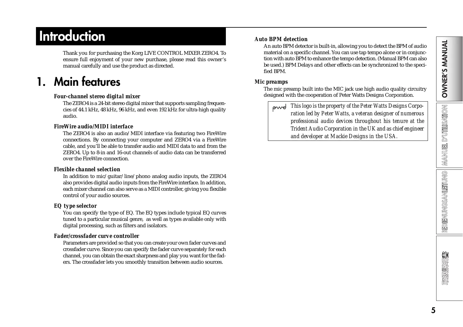
Thank you for purchasing the Korg LIVE CONTROL MIXER ZERO4. To ensure full enjoyment of your new purchase, please read this owner's manual carefully and use the product as directed.
1. Main features
Four-channel stereo digital mixer
The ZERO4 is a 24-bit stereo digital mixer that supports sampling frequencies of 44.1 kHz, 48 kHz, 96 kHz, and even 192 kHz for ultra-high quality audio.
FireWire audio/MIDI interface
The ZERO4 is also an audio/MIDI interface via featuring two FireWire connections. By connecting your computer and ZERO4 via a FireWire cable, and you'll be able to transfer audio and MIDI data to and from the ZERO4. Up to 8-in and 16-out channels of audio data can be transferred over the FireWire connection.
Flexible channel selection
In addition to mic/guitar/line/phono analog audio inputs, the ZERO4 also provides digital audio inputs from the FireWire interface. In addition, each mixer channel can also serve as a MIDI controller, giving you flexible control of your audio sources.
EQ type selector
You can specify the type of EQ. The EQ types include typical EQ curves tuned to a particular musical genre, as well as types available only with digital processing, such as filters and isolators.
Fader/crossfader curve controller
Parameters are provided so that you can create your own fader curves and crossfader curve. Since you can specify the fader curve separately for each channel, you can obtain the exact sharpness and play you want for the faders. The crossfader lets you smoothly transition between audio sources.
Auto BPM detection
An auto BPM detector is built-in, allowing you to detect the BPM of audio material on a specific channel. You can use tap tempo alone or in conjunction with auto BPM to enhance the tempo detection. (Manual BPM can also be used.) BPM Delays and other effects can be synchronized to the specified BPM.
Mic preamps
The mic preamp built into the MIC jack use high audio quality circuitry designed with the cooperation of Peter Watts Designs Corporation.
pawd
This logo is the property of the Peter Watts Designs Corporation led by Peter Watts, a veteran designer of numerous professional audio devices throughout his tenure at the Trident Audio Corporation in the UK and as chief engineer and developer at Mackie Designs in the USA.
2. Parts of the ZERO4
Top panel
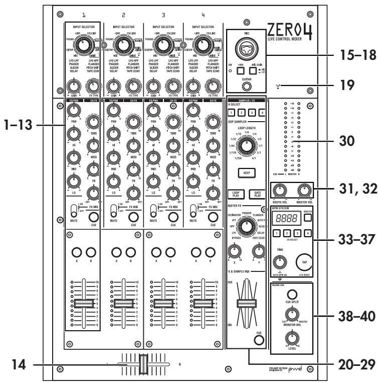
Selects the input jack or FireWire audio signal that will be assigned to the mixer channel. With this knob in certain positions, the send knobs, pan knob, EQ knobs and/or faders will operate as MIDI controllers.
2. GAIN knob
Adjust the gain of the audio input assigned to the mixer channel.
TIP: If the MIC input level is too high, causing the sound to distort, press the top panel MIC GAIN switch to change the mic preamp gain to LOW.
3. FX TYPE knob
This selects the type of channel effect that will be inserted into the mixer channel.
4. PAN knob
Adjusts the left/right audio balance.
5. EQ knobs
Normally, the HI, MID, and LO knobs boost or cut the sound in each frequency range. Depending on the type of EQ selected in the previous step, the function of the knobs may change.
6. TIME knob
This adjusts the time or other parameter of the effect selected by the FX TYPE knob. The result will depend on the effect that is selected.
7. MOD knob
This adjusts the modulation or other parameter of the effect selected by the FX TYPE knob. The result will depend on the effect that is selected.
8. FB knob
This adjusts the feedback or other parameter of the effect selected by the FX TYPE knob. The result will depend on the effect that is selected.
9. FX MIX knob
This adjusts the DRY/WET ratio of the channel effect.
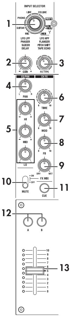
10. FX ON/MUTE switch
If you move this switch to the FX ON position, the channel effect of that mixer channel will be enabled, using the wet/dry mix you set with FX MIX knob (9.). If you return the switch to the center position, the channel effect will not be applied.
If you hold the switch in the MUTE position, the sound of that mixer channel will be muted.
TIP: You can't leave the switch set to the MUTE position.
11. CUE button
When the CUE button is lit (ON), the pre-fader sound of that mixer channel will be sent to the CUE bus. By setting the MONITOR BAL knob toward CUE, you can monitor the sound of the CUE bus through headphones.
12. A, B buttons
By pressing the A or B button you can assign this mixer channel to either side of the crossfader (crossfader channel A or B).
13. Channel fader
Adjusts the level of the input audio assigned to this mixer channel.
14. Crossfader
Crossfades the sounds that are assigned to the crossfader's channel A and channel B, and outputs the result to the master bus.
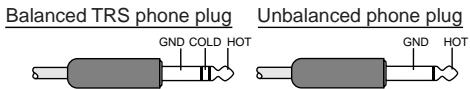
15. MIC INPUT jack
This is a combo-type balanced input jack that allows the use of TRS phone plugs or XLR plugs (+48V phantom power is supplied).
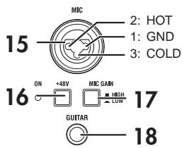
16. +48V PHANTOM switch
This turns the phantom power supply on/off for the MIC INPUT jack.
Phantom power is supplied only to the balanced XLR jack, not to the phone jack.
Note: If you connect or disconnect a condenser mic with the phantom power switch turned on, you risk damaging your equipment. Make sure that the phantom power switch is off before you connect or disconnect a condenser mic.
Caution: Never connect any device other than a condenser mic if the phantom power switch is on. Doing so may damage your equipment.
17. MIC GAIN switch
This sets the mic preamp gain for the MIC INPUT jack.
18. GUITAR jack
Connect a guitar or bass guitar to this jack.
This is a 1/4" phone-type unbalanced input jack.
19. FireWire indicator
If the ZERO4 is connected to your computer via a FireWire cable, this indicator will light when the connection is detected.
TIP: Start up your host application after this indicator has lit.
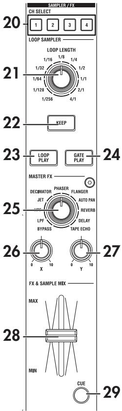
20. CH SELECT switch
This switches the send to the SAMPLER/FX bus. The LED of the selected channel will light, and all sound of the mixer channel will be sent to the SAMPLER/FX bus. You may select more than one channel simultaneously.
LED lit: The audio of the mixer channel will be connected to the SAM-PLER/FX bus. This will be the source audio for the loop sampler and master effect.
LED dark: The audio of the mixer channel will not be sent to the SAM-PLER/FX bus.
21. LOOP LENGTH knob
This specifies the recording/playback time of the loop sampler.
22. KEEP button
This indicates the sample hold status of the loop sampler. If a sample is already being held, pressing the KEEP button will erase the sample.
LED lit: A sample is being held.
LED dark: No sample is being held.
23. LOOP PLAY button
This records/plays the loop sampler. If no sample is being held, this button will initiate recording. If a sample is being held, this button will initiate loop playback.
- GATE PLAY button
This records/plays the loop sampler. If no sample is being held, this button will initiate recording. If a sample is being held, this button will initiate gate playback.
- MASTER FX TYPE knob
This selects the master effect type.
- X knob
This adjusts a parameter of the master effect. The result will depend on the master effect type.
- Y knob
This adjusts a parameter of the master effect. The result will depend on the master effect type.
This adjusts the mix balance between the loop sampler / master effect bus input (dry) sound, and the output (wet) sound.
- MASTER FX & SAMPLE CUE button
If you press this button to make the LED light, the audio of the loop sampler / master effect bus will be sent to the CUE bus.
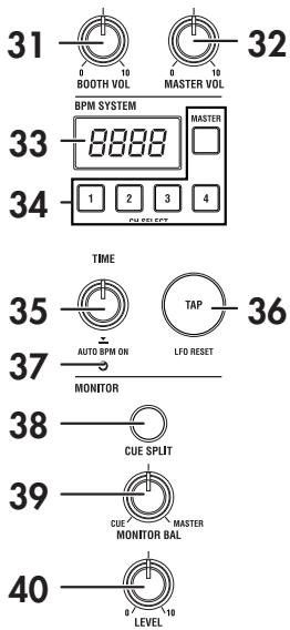
- Master level meter
This level meter indicates the level of the master out. If clipping occurs, the red LED will light; adjust the master out level so that this indicator does not light.
- BOOTH volume knob
Adjusts the output level from the BOOTH OUT jacks. This will output the same sound as the MASTER OUT jacks.
- MASTER volume knob
Adjusts the output level from the MASTER OUT jacks.
- BPM display
This indicates the currently-specified BPM value.
- BPM CH SELECT switch
This selects the source from which BPM will be detected when the AUTO BPM function is on.
- TIME/AUTO push knob
This specifies the BPM used for BPM sync effects and as the MIDI clock master. You can switch the AUTO BPM function on/off by pressing the push knob.
- TAP button
The timing interval at which you press this button is used to set the BPM value or as a guide for auto BPM detection.
If you've selected an effect that uses the LFO, this button will reset the LFO.
- AUTO BPM indicator
This will light if the auto BPM counter is on.
- SPLIT button
This switches the Split function on/off for the headphone monitor.
LED lit: The CUE audio will be output from headphone L, and the master audio will be output from headphone R. In this case, the L side of the master level meter will indicate the CUE level, and the R side will indicate the master level.
LED dark: The CUE and MASTER audio will be output at the balance adjusted by the MONITOR BAL knob.
- MONITOR BAL knob
If this is turned toward CUE, the headphones will monitor the CUE bus. If this is turned toward MASTER, the headphones will monitor the MASTER OUT jacks. This knob does nothing if the Split function is on.
- MONITOR LEVEL knob
Adjusts the headphone volume.
Front panel
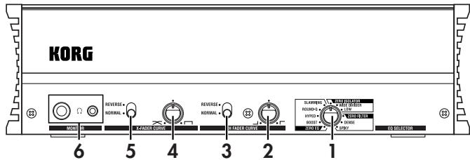
1. EQ SELECTOR knob
This selects the EQ type.
By switching the type, you can change the way in which the tone is modified when the HI/MID/LO bands are adjusted. This setting applies to the EQ of all channels.
2. Channel fader shape knob
This adjusts the fader curve of the channel faders. This setting applies to the fader curve of all channels.
TIP: The fader curve you've specified using ZEROEdit will be reset to the same curve for all channel faders if you operate the channel fader shape knob.
3. Channel fader reverse switch
This reverses the operation of the channel faders between the normal and inverted directions. This setting applies to the fader curves of all channels.
4. Crossfader curve knob
This adjusts the fader curve of the crossfader.
Turn the crossfade curve knob toward the left to crossfade smoothly. Turn the knob toward the right to make an abrupt switch.
5. Crossfader reverse switch
This changes the operation of the crossfader between normal and inverted directions.
6. Headphone jacks (phone and stereo-mini)
You can connect headphones to the headphone jack to monitor the audio of the MONITOR bus or CUE bus.
Note: The phone/stereo-mini headphone jacks will output the same audio. The volume may be less if you connect both headphone jacks at the same time.
Rear panel
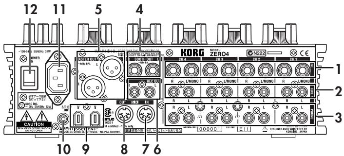
1. INPUT 1-4 (LINE) jacks
These are 1/4" TRS phone-type balanced input jacks.
2. INPUT 1-4 (CD/LINE) jacks
These are RCA-type unbalanced input jacks.
3. PHONO 1-4 jacks, GND terminal
These are phono input jacks for connecting turntables; a grounding terminal is also provided.
4. BOOTH OUT jacks
These outputs provide the same audio signal as the MASTER OUT jacks. You can use the BOOTH knob to adjust the BOOTH OUT jacks to a different level than MASTER OUT.
These are 1/4" TRS phone-type balance output jacks.
5. MASTER OUT (XLR) jacks
These jacks output the audio of the master bus.
6. REC OUT (RCA) jacks
These jacks output the audio of the master bus.
7. MIDI IN connector
This connector receives MIDI messages. Incoming MIDI messages can be sent to your computer via the FireWire connector.
8. MIDI OUT connector
This connector re-transmits (“thru-es”) the MIDI messages received from your computer via the FireWire connector. It also transmits MIDI messages produced by the ZERO4 itself.
9. FireWire connector
You can connect the ZERO4 to your computer and use it as an audio/MIDI interface.
The two connectors operate in the same way. The connector not connected to your computer can be used for daisy-chain connections.
10. DIGITAL OUT (coaxial) jack
This is a S/PDIF type digital output. It outputs the same audio as the MASTER OUT jacks in digital form.
You can connect this to the input jack of a consumer digital audio device.
It is an RCA phono-type coaxial jack.
11. Power inlet
Connect the included power cable to this connector.
12. Power switch
Turns the power on/off.
Connections and Operation
1. Preparations
Before you connect your equipment, you must turn off the power and disconnect the power cable from the AC outlet.
Connecting your output devices
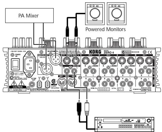
Master Recorder (Analog input)
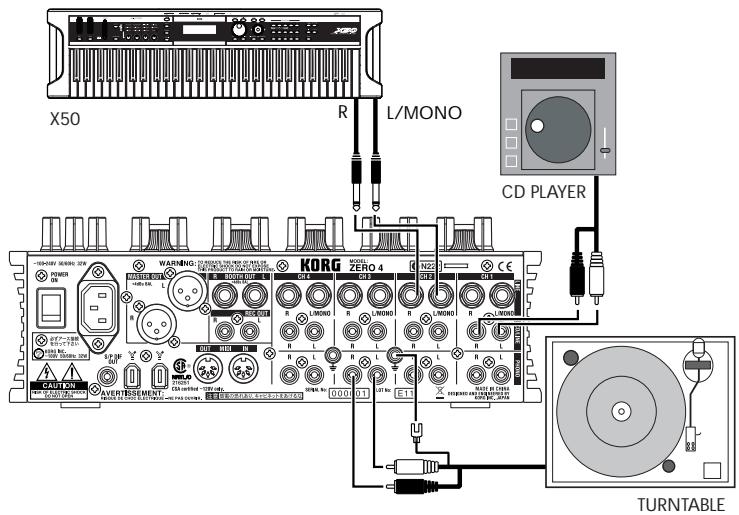
Connecting your input devices
Use the appropriate jacks for the devices you're connecting.
Mic: MIC jacks (TRS phone jack or balanced XLR jack)
Guitar: GUITAR jack
Sampler, keyboard, etc.: LINE jacks (TRS phone-type balanced input jacks)
CD player: CD/LINE jacks (RCA type unbalanced input jacks)
Turntable: PHONO input jacks and ground connector
Turning the power on
When powering-on the ZERO4, you must use the following order.
- Connect the power cable.
Connect the included power cable to the power inlet. - Power-on the external equipment that's connected to the input jacks.
- Turn down the ZERO4's MASTER VOLUME knob.
- Turn on the power switch located on the ZERO4's rear panel.
- Power-on your monitor amp and the amp that is connected to the MASTER OUT jacks.
Turning the power off
- Turn down the ZERO4's MASTER VOLUME knob.
- Turn off the power of your monitor amp and the amp connected to the MASTER OUT jacks.
- Turn off the power switch located on the ZERO4's rear panel.
2. Using the mixer
Selecting the inputs
Here's how to assign a set of input jacks to a specific mixer channel.
- Use the top panel INPUT SELECTOR knob to select the desired input.
The knobs of each mixer channel for which you selected an audio input will light orange.
Knobs that are operating as MIDI controllers will light green.
| MIC | Select the sound of the device connected to the MIC INPUT jack. |
| GUITAR | Selects the sound of the device connected to the GUITAR jack. |
| PHONO | Selects the sound of the device connected to the PHONO jacks. |
| LINE | Selects the sound of the device connected to the LINE jacks. |
| CD/LINE | Selects the sound of the device connected to the CD/LINE jacks. |
| FireWire AUDIO | Selects the sound of the computer connected to the FireWire connector. |
| FireWire AUDIO + MIDI | Selects the sound of the computer connected to the FireWire connector. In this case, the TIME, FB, MOD and FX MIX knob will operate as MIDI controllers. |
| MIDI CONTROL | The controllers of the mixer channel will operate as MIDI controllers. |
TIP: If you've selected "FireWire AUDIO" or "FireWire AUDIO + MIDI," the output to the FireWire connector will be the pre-EQ signal of the source connected to the PHONO jacks.
Adjusting the input levels
Adjust the GAIN knob
Adjust this knob so that the GAIN knob does not light red even when the maximum level is being input.
TIP: If you're using mic input and have connected a mic that has a high output, set the MIC GAIN switch to LOW.
Mixing the sounds
- Use the fader of each mixer channel to adjust its volume level.
- Use the PAN knob of each mixer channel to adjust its stereo position.
Crossfader
You can use the crossfader to crossfade between the sounds you've assigned to crossfader channels A and B. By using the crossfader you can perform DJ techniques such as switching instantly between the sounds of two channels or crossfading smoothly between them.
- For the mixer channel that you want to assign to crossfader channel A, press the A button to turn it on (the LED will light).
You may turn on the A button for more than one mixer channel if desired. - For the mixer channel that you want to assign to crossfader channel B, press the B button to turn it on (the LED will light).
- To cancel this setting, simply press a lit button once again.
If a mixer channel is not assigned to either channel A or B (i.e., if neither of these LEDs are lit), the sound of that mixer channel will be sent to the master bus without passing through the crossfader.
Master output / Booth output
The mixed sound is output from the MASTER OUT jacks and the BOOTH OUT jacks.
The same mixed sound is output from both sets of jacks, but you can use the MASTER VOL knob and BOOTH VOL knob to independently adjust each one to a different volume.
Adjusting the volume
- Use the MASTER VOL knob to adjust the volume of the MASTER OUT jacks.
Adjust the volume to a level that does not cause the level meter to light red. - Use the BOOTH VOL knob to adjust the volume of the BOOTH OUT jacks.
- Use the MONITOR LEVEL knob to adjust the volume of the headphones.
Monitoring
Connect headphones to the headphone jack so that you can refer to the mixed sound or the audio inputs.
CUE
This function lets you monitor your performance through headphones without outputting it from the MASTER OUT jacks. To monitor the sound of the CUE bus through headphones, turn the monitor section MONITOR BAL knob toward the CUE position. In this state, you can leave a fader lowered but turn CUE on and use your headphones to check the sound adjusted by EQ and the channel effect; then when you've adjusted the sound to your liking, raise the channel fader to output the sound from the master outputs.
Monitoring via CUE
By turning on the CUE switch of a mixer channel, you can send its prefader sound to the CUE bus.
-
Turn on the CUE button of the mixer channel you want to monitor.
-
Use the MONITOR BAL knob to adjust the volume balance of the master output sound and the CUE bus sound.
Use the MONITOR LEVEL knob to adjust the overall volume.
- By turning the SPLIT switch on, you can hear the CUE signal from the L side of the monitor, and the master output from the R side of the monitor.
When SPLIT is on, the MONITOR BAL knob does nothing.
3. Equalizer
Using the equalizer to adjust the sound
Traditionally, an equalizer (EQ) divides the sound into different frequency regions, allowing you to shape the tonal character of the sound by boosting or cutting the output of each region. In more modern applications, the EQ can be used as an effect, providing filter sweeps and isolator functions. The ZERO4 provides 11 different types of EQ.
- Use the EQ SELECTOR knob to select the equalizer type.
EQ type: These are a variety of EQ types with frequency responses suitable for different styles. Choose the type that's appropriate for your needs.
- Zero EQ
- Boost
- Hyped
- Round-Q
- Slamming
ISOLATOR type: This is a -12dB/oct isolator. It divides the input sound into frequency regions, and allows you to individually cut the sound of each region. If you turn the knobs of all regions completely toward the left, the sound will disappear completely.
- ZERO Isolator
- ZERO ISOLATOR WIDE DIVIDER
- ZERO ISOLATOR LOW
FILTER type: These are filter types in which HI is an LPF and LO is a HPF. Turning HI down (toward the left) will lower the cutoff frequency of the LPF. Turning LO down (toward the left) will raise the cutoff frequency. MID operates as a peaking EQ.
- ZERO FILTER
- ZERO FILTER DENSE
-
ZERO FILTER SPIKY
-
Use the EQ knobs to control the type of EQ you selected.
Adjust the three bands (HI/MID/LO) to obtain the desired tone.
4. BPM system
In the ZERO4, the BPM (Beats Per Minute) setting is used as the master clock for MIDI and for effects that are synchronized to the BPM. The ZERO4 has an Auto BPM function that automatically detects the BPM from an audio input source. You can also set the BPM manually.
Setting the BPM manually
Turn the TIME/AUTO push knob to specify the desired BPM.
Setting the BPM using tap tempo
Press the TAP button at least three times to the beat of the song. The interval at which you pressed the button will be calculated, and specified as the BPM value.
Setting the BPM automatically
Here's how you can use the Auto BPM Counter to detect the BPM of a song that's being input
- Press the BPM CH SELECT button to select the source whose BPM you want to detect.
- Press the TIME/AUTO push knob to turn AUTO BPM on; the BPM will be detected automatically.
If the BPM was detected incorrectly, leave AUTO BPM turned on, and press the TAP key at the beat of the song; the BPM will be automatically detected using your beat as a guide. If AUTO BPM is on, changes in the BPM of the audio input are detected automatically, and the BPM is adjusted accordingly.
TIP: The BPM cannot be detected correctly for songs that don't have a definite beat.
5. Channel effects
The channel effects are inserted into each mixer channel.
You can choose from eight different effect types, and operate the TIME, MOD, FB, and FX MIX knobs to control the sound.
| TIME knob | Adjusts a time- or speed-related parameter. |
| MOD knob | Adjust a parameter that applies modulation to the sound. |
| FB knob | Adjusts a feedback-related parameter. |
| FX MIX knob | Adjusts the DRY/WET amount of the effect (common to all types). |
Effect type list
| LFO LPF | A low pass filter whose cutoff frequency is varied by an LFO.TIME: Adjusts the LFO speed.MOD: Adjusts the depth of LFO modulation.FB: Adjusts the amount of resonance. |
| LFO HPF | A high pass filter whose cutoff frequency is varied by an LFO.TIME: Adjusts the LFO speed.MOD: Adjusts the depth of LFO modulation.FB: Adjusts the amount of resonance. |
| PHASER | An effect that creates modulation by using an LFO to shift the phase of the sound.TIME: Adjusts the LFO speed.MOD: Adjusts the depth of LFO modulation.FB: Adjusts the amount of resonance. |
| FLANGER | An effect that creates intense modulation and a sense of pitch movement. It is effective when applied to a sound that contains numerous overtones.TIME: Adjusts the LFO speed.MOD: Adjusts the depth of LFO modulation.FB: Adjusts the amount of feedback. |
| SLICER | Cuts the sound in synchronization with the BPM.TIME: Adjusts the interval at which the sound is cut.MOD: Adjusts the proportion for which sound |
| will be heard during the interval specified by the TIME knob.FB: Adjusts the amount of change to the shape of the LFO waveform. | |
| PITCH SHIFT | Shifts the pitch of the input audio upward or downward.TIME: Adjusts the delay time.MOD: Adjusts the pitch of the input audio.FB: Adjusts the amount of feedback for the pitch-shifted sound. |
| DELAY | A stereo delay.TIME: Adjusts the delay time.MOD: Adjusts the time before reaching the delay time specified by TIME.FB: Adjusts the amount of feedback. |
| TAPE ECHO | An effect that simulates a tape echo.TIME: Adjusts the delay time.MOD: Adjusts the output level.FB: Adjusts the amount of feedback. |
The display indication when operating the TIME knob
When you operate the TIME knob, the specified TIME parameter is shown in the display for approximately two seconds. The number shown indicates the beat. For example, a beat of 1/4 (quarter note) is shown as “1.4” in the display.
Limitations on the delay time
Depending on the combination of the BPM synchronization setting and the TIME parameter, the TIME parameter of the channel effect may exceed the allowable range. If this occurs, the display will indicate “FULL,” and the delay time will be set to the maximum allowable setting.
6. Loop Sampler and Master Effect
The loop sampler and the master effect are connected to the SAMPLER/FX bus in series.
Input channel selection and mixing
The audio of the mixer channel selected by the CH SELECT switch is sent to the SAMPLER/FX bus, and will be the input signal for the loop sampler and master effect.
The MASTER FX & SAMPLE MIX fader will adjust the mix balance between the sound that has passed through the loop sampler and master effect, and the sound (“dry” sound) selected by the CH SELECT switch. By pressing the CUE button, you can monitor the “wet” sound via the CUE bus even if this is set to the “dry” side.
Loop sampler
This is a loop sampler that lets you play the recorded sample using either Gate Play or Loop Play methods.
Operating procedure
- Specify the recording/playback time.
The recording/playback time is specified by the LOOP LENGTH knob, relative to the BPM.
Use the LOOP LENGTH knob to specify the number of beats that will be recorded/played-back. For example if you set the LOOP LENGTH knob to “1/4”, the length will be one quarter-note beat. The duration of one beat depends on the BPM value. (Refer to the table. Units are seconds.)
| BPM | 120 | 40 | 60 | 200 | 300 |
| 1/256 | 0.008 | 0.023 | 0.015 | 0.005 | 0.003 |
| 1/32 | 0.625 | 0.186 | 0.125 | 0.375 | 0.025 |
| 1/8 | 0.25 | 0.75 | 0.5 | 0.15 | 0.1 |
| 1/4 | 0.5 | 1.5 | 1 | 0.3 | 0.2 |
| 1/1 | 2 | 6 | 4 | 1.2 | 0.8 |
| 4/1 | 8 | 24 | 16 | 4.8 | 3.2 |
- Using Gate Play and Loop Play.
To sample with Gate Play
When you press the GATE PLAY button, sampling will occur only for the time specified by the LOOP LENGTH knob.
Loop playback will continue while you continue holding down the GATE PLAY button.
Loop playback will stop when you release the GATE PLAY button.
The KEEP button will blink, and the sample data will be preserved.
To sample with Loop Play
When you press the LOOP PLAY button, recording will occur only for the time specified by the LOOP LENGTH knob, and then loop playback will continue even after you release the LOOP PLAY button.
When you press the LOOP PLAY button once again, loop playback will stop.
The KEEP button will blink, and the sample data will be preserved.
3. Record the sample.
If the KEEP button is blinking, this indicates that the sampled data is temporarily preserved. If you continue sampling, this data will be overwritten.
If you store the sampled data, you'll be able to play back this sample repeatedly.
The KEEP button indicates the storage status of the sample data.
If the KEEP button dark: No sample has been preserved.
If the KEEP button is blinking: The sample has been temporarily preserved.
If you press the blinking KEEP button, the temporarily preserved sample data will be stored into internal memory. When the sample data has been stored, the KEEP button will light.
If you press the GATE PLAY button or LOOP PLAY button while the KEEP button is blinking, new sampling will begin, and the temporarily preserved sample will be erased.
If the KEEP button is lit: The sample has been stored in internal memory.
4. Play back the sample data.
To play back using Gate Play
The stored sample will play as a loop while you hold down the GATE PLAY button. You can use the LOOP LENGTH knob to change the length of playback.
Loop playback will stop when you release the GATE PLAY button.
To play back using Loop Play
When you press the LOOP PLAY button, the stored sample will play as a loop for the duration specified by the LOOP LENGTH knob. Loop playback will stop when you press the LOOP PLAY button once again.
Note: The input to the SAMPLER/FX bus is cut off during loop play. The master effect is applied only to the loop playback.
5. Delete the stored sample data.
When you press the lit KEEP button, the sample data stored in internal memory will be erased, and the KEEP button will go dark.
Note: It's not possible to permanently save the recorded sample. Regardless of whether the sample was temporarily preserved or stored in internal memory, it will be lost when you turn off the power.
Master effect
The master effect is connected in series with the loop sampler. You can use the X and Y knobs to control the change produced by the master effect.
Effect type list
| LPF | A low pass filter with adjustable cutoff frequency and resonance. |
| X: Adjusts the cutoff frequency. | |
| Y: Adjusts the resonance. | |
| HPF | A high pass filter with adjustable cutoff frequency and resonance. |
| X: Adjusts the cutoff frequency. | |
| Y: Adjusts the resonance. | |
| JET | A flanging effect that adds a time-shifted sound to create an effect reminiscent of a jet airplane taking off and landing. |
| X: Adjusts the frequency region at which the flanging effect is applied. | |
| Y: Adjusts the amount of feedback. | |
| DECIMATOR | An effect that lowers the sampling frequency and bit depth of the data, producing a gritty sound reminiscent of an inexpensive sampler. |
| X: Adjusts the sampling frequency. | |
| Y: Adjusts the bit depth. | |
| PHASER | An effect that creates modulation by using an LFO to change the phase of the sound. |
| X: Adjusts the LFO speed. | |
| Y: Adjusts the amount of resonance. | |
| FLANGER | An effect that creates an intense modulation and sense of pitch change. This is effective when applied to sounds that contain numerous overtones. |
| X: Adjusts the LFO speed. | |
| Y: Adjusts the amount of feedback. | |
| AUTO PAN | An effect that uses an LFO to move the stereo position between left and right. |
| X: Adjusts the LFO speed. | |
| Y: Adjusts the depth of LFO modulation. |
| REVERB | An effect that simulates the reverberant ambience of a hall. |
| X: Adjusts the reverberation time. | |
| Y: Adjusts the reverberation level. | |
| DELAY | A stereo delay. |
| X: Adjusts the delay time. | |
| Y: Adjusts the feedback. | |
| TAPE ECHO | An effect that simulates a tape echo. |
| X: Adjusts the delay time. | |
| Y: Adjusts the amount of feedback. |
FireWire interface functions
You can connect the ZERO4 to your computer via a FireWire cable and use it as an audio/MIDI interface.
Note: This device does not supply bus power.
Note: Do not simultaneously connect more than one computer to the ZERO4.
Note: If you are using a host application such as sequencing software, you'll need to make audio and MIDI device settings. For details, refer to the owner's manual of the software you're using.
Note: You must connect the ZERO4 to your computer using a FireWire cable and turn on the power before you start up your software. Don't disconnect the FireWire cable or power-off the ZERO4 while the software is running.
Note: If you're using the ZERO4 with Mac OS X, turn off the Sleep setting and power management settings.
Note: Each input/output device can be used with only one software application. Multi-client operation is not supported.
Note: Use the included CD-ROM to install the "KORG FireWire Audio/MIDI driver" into the computer you're using. (p.23)
1. FireWire audio interface
You can use the ZERO4 as an audio interface. This lets you send the ZERO4's audio inputs or mixed sound to your computer, and send the audio outputs from a host application on your computer to the ZERO4. Your FireWire-connected computer will detect the ZERO4 as an audio interface that provides a maximum of 8-in and 16-out audio streams.
Limitations for different sampling rates
If the ZERO4 is connected to your computer, you'll be able to change the sampling rate from the control panel of the host application or audio driver.
The available number of effects and mixer channels will depend on the sampling rate you select.
44.1 kHz or 48 kHz operation: Four stereo channels + channel effects, loop sampler, master effect
96 kHz operation: Four stereo channels
Note: When operating at 96 kHz, the channel effects, loop sampler, and master effect are not available.
Note: When using the ZERO4 with Mac OS X
Depending on the system you're using, you may experience problems such as the operating system becoming unstable when you switch the sampling frequency.
If this occurs, you can start up as described below so that the ZERO4 will operate with a fixed sampling frequency. In this case, you won't be able to switch to another sampling frequency from the computer.
44.1 kHz: Turn on the power while holding down the mixer channel 1 Cue button.
48 kHz: Turn on the power while holding down the mixer channel 2 Cue button.
96 kHz: Turn on the power while holding down the mixer channel 3 Cue button.
In the Mac OS System Settings / Sound / Output dialog box, verify that the ZERO4 has disappeared from the list of sound output devices, and then turn the power on once again.
Depending on the type of computer you're using, starting up the computer with the ZERO4 already connected may cause operation to become unstable. In this case, connect the ZERO4 after the computer has started up.
Using the ZERO4 at the 192 kHz sampling rate
By starting up the ZERO4 in the special 192 kHz audio mode, you can use it as a high-quality 24-bit/192 kHz 8-in/8-out audio interface.
Note: When using Mac OS X, the 192 kHz sampling rate is not supported.
Starting up in 192 kHz audio mode
While holding down the KEEP button, turn on the power.
Note: If you start up in 192 kHz audio mode, you won't be able to switch to other sampling rates (44.1 kHz, 48 kHz, 96 kHz). If you want to switch to a different sampling rate, you must turn off the power and then turn the power on again to start up in the normal way.
Limitations in 192 kHz audio mode
The specifications are limited as follows when operating in the special 192 kHz mode.
• Number of channels: Four stereo channels (8-in/8-out)
• Channel EQ: Not available
- Channel effects, loop sampler, master effect: Not available
Controller operation when in 192 kHz audio mode
Channel Controller
| INPUT SELECTOR | Operates normally |
| GAIN | Operates normally |
| FX TYPE | MIDI controller |
| PAN | MIDI controller |
| HI | MIDI controller |
| MID | MIDI controller |
| LO | MIDI controller |
| TIME | MIDI controller |
| MOD | MIDI controller |
| FB | MIDI controller |
| FX MIX | MIDI controller |
| FX ON | MIDI controller |
| MUTE | Operates normally |
| CUE | Operates normally |
| A | Operates normally |
| B | Operates normally |
| CH FADER | Operates normally |
| Master Controller | |
| CH SELECT (SAMPLER/FX) | Not available |
| LOOP LENGTH | Not available |
| KEEP | Not available |
| LOOP PLAY | Not available |
| GATE PLAY | Not available |
| MASTER FX TYPE | Not available |
| X | Not available |
| Y | Not available |
| MASTER FX & SAMPLE MIX | Not available |
| CUE | Not available |
| BOOTH VOL | Operates normally |
| MASTER VOL | Operates normally |
| SPLIT | Operates normally |
| MONITOR BAL | Operates normally |
| MONITOR LEVEL | Operates normally |
| CROSSFADER | Operates normally |
| CROSSFADER CURVE | Operates normally |
| CROSSFADER REVERSE | Operates normally |
| CH FADER CURVE | Operates normally |
| CH FADER REVERSE | Operates normally |
| EQ SELECT | Not available |
2. FireWire MIDI interface
A MIDI device connected to the ZERO4's MIDI IN/OUT connectors can communicate with your computer via the FireWire connector.
About MIDI
MIDI stands for Musical Instrument Digital Interface, and is a world-wide standard that allows electronic musical instruments and computers to exchange a wide variety of performance-related information.
About the MIDI implementation chart
The owner's manual of each MIDI device includes a “MIDI implementation chart.” This chart makes it easy to determine the types of MIDI messages that each device is able to transmit or receive. When using two MIDI devices, you can compare their MIDI implementation charts to see whether the messages transmitted by one device will be recognized by the other device. The MIDI implementation chart for this device is provided on the CD-ROM.
Note: Details of the MIDI functionality are provided in the MIDI implementation, which can be found on the included CD-ROM.
Using the ZERO4 as a MIDI controller
In addition to functioning as a mixer, the ZERO4 can also be used as a realtime controller that transmits MIDI messages to control an application on your computer or an external MIDI device such as a synthesizer.
Connecting to your computer
-
Install the MIDI driver.
Use the included CD-ROM to install the “KORG FireWire Audio/MIDI driver” in your computer. (p.24)
TIP: If you're using a Macintosh, you don't need to install a driver. -
Use a FireWire cable to connect the ZERO4 to your computer.
-
Make sure that your computer has detected the ZERO4.
-
Start up your host application.
Note: When you connect the ZERO4 to your computer via a
FireWire cable, it will be detected as a "3-in/3-out" MIDI interface. In this connection, "ZERO 1" is used to communicate between the ZERO4 and the included "ZERO Edit" editor software. "ZERO 2" is used to exchange MIDI messages between the ZERO4 and your MIDI host application such as a DAW. "ZERO 3" will operate as a MIDI interface used to exchange messages with an external MIDI device connected to the ZERO4's MIDI connectors. (p.22)
Note: Depending on the DAW or other MIDI host application you're using, the application may allocate all of the MIDI ports when it is started-up.
If you want to use this type of application at the same time as the “ZERO Edit” editor for the ZERO4, you must start up ZERO Edit first and allow it to detect and connect the “ZERO 2” MIDI port. Then start up your MIDI host application, and you’ll be able to use the ZERO Edit software and your other application at the same time.
Using the controllers of the mixer channels as MIDI controllers
-
Turn the INPUT SELECTOR knob to MIDI.
For the mixer channel you want to use as a controller, turn the INPUT SELECTOR knob to the MIDI position. -
When you operate the knobs/switches of the selected mixer channel, the MIDI control messages assigned to each controller will be transmitted.
At this time, the audio received at the LINE input jacks of the selected mixer channel will be output to the master bus. However, you won't be able to adjust the fader, EQ, or PAN. Use the GAIN knob to adjust the volume.
- You can use the dedicated ZERO Edit editor software to change the MIDI messages assigned to each controller.
FireWire Audio/MIDI device name list
MIDI Device
| PortNo. | MIDI IN | MIDI OUT | Remarks |
| 1 | ZERO 1 | ZERO 1 | Only for ZERO Edit |
| 2 | ZERO 2 | ZERO 2 | Only for MIDI controllers |
| 3 | ZERO 3 | ZERO 3 | For external MIDI IN/OUT connectors |
Note: Depending on the application you're using, the application may display its own port name rather than obtaining the name from the ZERO4.
Audio Device
| PortNo. | Audio Input Audio Output | Corresponds to input jack Corresponds to output jack (factory settings *1) |
| 1 | ZERO 1L | CH1L |
| ZERO 1L | CH1 L PRE EQ | |
| 2 | ZERO 2L | CH1R |
| ZERO 2L | CH1 R PRE EQ | |
| 3 | ZERO 3L | CH2L |
| ZERO 3L | CH2 L PRE EQ | |
| 4 | ZERO 4L | CH2R |
| ZERO 4L | CH2 R PRE EQ | |
| 5 | ZERO 5L | CH3L |
| ZERO 5L | CH3 L PRE EQ | |
| 6 | ZERO 6L | CH3R |
| ZERO 6L | CH3 R PRE EQ | |
| 7 | ZERO 7L | CH4L |
| ZERO 7L | CH4 L PRE EQ | |
| 8 | ZERO 8L | CH4R |
| ZERO 8L | CH4 R PRE EQ | |
| 9 | --- | |
| ZERO 9L | BUS A L | |
| 10 | --- | |
| ZERO 10L | BUS A R |
| 11 | ---ZERO 11L | BUS B L |
| 12 | ---ZERO 12L | BUS B R |
| 13 | ---ZERO 13L | FX OUT L |
| 14 | ---ZERO 14L | FX OUT R |
| 15 | ---ZERO 1L | MASTER L |
| 16 | ---ZERO 1L | MASTER R |
| 17 | ZERO INVALID AUDIO 1 | |
| 18 | ZERO INVALID AUDIO 2 |
Note: In some cases, audio input ports number 17 and number 18 on your computer may show a port name such as “ZERO INVALID AUDIO1, INVALID AUDIO2” or “INPUT17, INPUT18.” These audio input ports are invalid, and cannot be used.
Note: Depending on the application you're using, the application may display its own port name rather than obtaining the name from the ZERO4.
*1: The output locations of the audio output ports can be changed by using System Setup or the ZERO Edit application.
MIDI connections
In order to send and receive MIDI messages via the MIDI connectors, you will need to obtain commercially-available MIDI cables. Connect these cables between the ZERO4's MIDI connectors and the MIDI connectors of your external MIDI device.
MIDI IN connector: This receives MIDI messages from another MIDI device. Connect it to the MIDI OUT connector of your external device.
MIDI OUT connector: This transmits MIDI messages from the ZERO4. Connect it to the MIDI IN connector of your external device.
Installing the software
Install the KORG FireWire Audio/MIDI driver and ZERO Edit software from the included CD-ROM into the computer to which you'll be connecting the ZERO4.
Contents of the CD-ROM
The included CD-ROM contains the following.
- ZERO Edit
• KORG FireWire Audio/MIDI driver - ZERO Edit owner's manual (PDF)
- Software license agreement (RTF)
• MIDI implementation chart (PDF) - MIDI implementation
Please note before use
• Copyright to all software included with this product is the property of Korg Corporation.
- The license agreement for the software included with this product is provided separately. You must read this license agreement before you install the software. Your installing the software will be taken to indicate your acceptance of this license agreement.
Operating requirements
Windows XP
Operating system: Microsoft Windows XP Home Edition / Professional Service Pack 2 or later
Computer: FireWire (IEEE1394) port is required
CPU: Pentium3 800 MHz or faster
Memory: 256 MB or more
Mac OS X
Operating system: Mac OS X 10.3.9 or later
Computer: FireWire (IEEE1394) port is required
CPU: PowerPC G3 800 MHz, PowerPC G4 733 MHz or better, or an Intel processor
Memory: 256 MB or more
1. Installing the driver and editor software in Windows XP
Note: You must have Administrator privileges in order to install or uninstall software in Windows XP. For details, please consult with your system administrator.
Note: You must use the ZERO4/ZERO8 application installer to install the KORG FireWire Audio/MIDI driver before you connect the ZERO4 to your computer via FireWire.
ZERO4/ZERO8 application installer
The ZERO4/ZERO8 application installer will automatically install the KORG FireWire Audio/MIDI driver and the ZERO Edit software into your computer.
- Insert the included CD-ROM into the CD-ROM drive of your computer.
Normally, the “ZERO4/ZERO8 Application Installer” will start up automatically.
If, due to settings on your computer, the installer does not start up automatically, double-click "KorgSetup.exe" on the CD-ROM.
- Following the instructions that appear in the screen, install the KORG FireWire Audio/MIDI driver and the ZERO Edit software.
Note: You must install the KORG FireWire Audio/MIDI driver if you want to use ZERO Edit via the FireWire port.
- When all of the selected software has been installed, exit the installer.
For details on the installation procedure, refer to the following section "Installing the KORG FireWire Audio/MIDI driver."
Installing the KORG FireWire Audio/MIDI driver
- Install the KORG FireWire Audio/MIDI driver as directed in the screen.
During the installation, a dialog box telling you that “... has not passed Windows logo testing” may appear, indicating that this driver does not have a digital signature. Simply click [Continue] to proceed.
Note: If you are unable to complete the installation, it may be that your computer has been set to prohibit installation of unsigned drivers. Check the settings of your computer as described in “Allowing installation of unsigned drivers.”
- When the following screen appears during the process of installing the KORG FireWire Audio/MIDI driver, connect the FireWire cable and power-on the ZERO4.
![KORG3 Firewire Audio/MIDI Driver V1.0 Setup Disconnect and reconnect devices and turn them on To complete the installation please disconnect and reconnect your device(s) and turn it/them on. Note: During this process the system may prompt you again to confirm installation of software that has not passed Windows Logo testing. Please select [Continue Anyway] to confirm installation. Click [Next] after you reconnected and turned on devices. Next >](/content/2019/11/143968/images/e37b5f725fc975b680106c872296d3c704f239095711166dfc9fab60dfbee6cd.jpg)
- When installation of the KORG FireWire Audio/MIDI driver has finished, exit the installer.
If you are asked to restart, choose [Yes] to restart your computer.
Setting up ZERO Edit
For details on how to set up and use ZERO Edit, refer to the “ZERO Edit operating manual.”
Allowing installation of unsigned drivers
If your computer has been set to prohibit the installation of unsigned drivers, you won't be able to install the KORG FireWire Audio/MIDI driver. Proceed as follows to change the setting so that the driver can be installed.
- In the taskbar, click [Start] + [Control Panel] to open the control panel.
- In the control panel, double-click [System], and then click the [Hardware] tab.
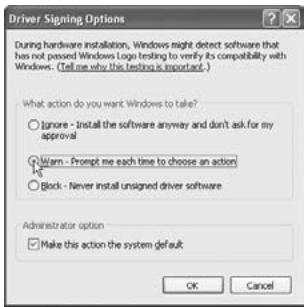
- In the “Drivers” field, click [Driver Signing].
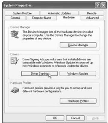
- In “What action do you want Windows to take?” choose [Ignore] or [Warn], and then click [OK].
If necessary, you can return this setting to its previous state after you've installed the KORG FireWire Audio/MIDI driver.
2. Installing the editor software in Mac OS X
Installing the software
Here's how to start up the ZERO Edit installer and install the software.
TIP: The ZERO4 uses the standard MIDI driver provided by MacOS, so you don't have to install a MIDI driver.
- Insert the included CD-ROM into the CD-ROM drive of your computer.
- In the CD-ROM, double-click the software installer (.pkg) to it start.
The installer is located in the following folder. "ZERO Edit" folder > ZERO Edit for MacOS X.pkg - Follow the instructions in the screen to install the ZERO Edit software.
- When the software has been installed, exit the installer.
Setting up ZERO Edit
For details on how to set up and use ZERO Edit, refer to the “ZERO Edit operating manual.”
Appendix
1. Troubleshooting
Power does not turn on
☐ Is the power cable connected to an electrical outlet?
☐ Is the rear panel power switch turned on?
No sound
☐ Is the ZERO4 powered-on? Are the connected devices powered-on?
☐ Are the channel faders or the MONITOR LEVEL knob turned down?
☐ Is the volume level of the channel turned down?
☐ Is the FX IN/MUTE switch set to MUTE?
☐ Is the GAIN knob raised to an appropriate level?
□ After connecting a device to an input jack, did you assign it correctly to the mixer channel?
Use the INPUT SELECTOR knobs to input the desired source into each mixer channel.
☐ Make sure that audio is being input.
Use the level meter to verify that audio is being received into each mixer channel.
☐ Could you have selected a MIDI controller setting as the input selection?
Use the INPUT SELECTOR knob to select an input jack.
Excessive noise or distortion
☐ Is the GAIN knob set appropriately?
The sound will be distorted if the GAIN knob is set too high, and there will be excessive noise if it is set too low.
To obtain the best sound quality, the GAIN knobs for the GUITAR, MIC, and INPUT 1–INPUT 4 jacks should be adjusted as high as possible without allowing the GAIN knob to light red.
□ Are you be using an effect?
Some of the effects intentionally add distortion or noise. Check whether distortion or noise occurs even if you're not using an effect.
☐ If the sound is distorting at the EQ, make the following adjustment.
Adjust the gain value of the EQ.
MIDI
MIDI sequencer will not synchronize / MIDI control does not work
☐ Are the MIDI cables connected correctly?
☐ Could a MIDI cable be broken?
☐ Are the synchronization-related settings of your MIDI sequencer correct?
Refer to the owner's manual for your MIDI sequencer.
Can't control via MIDI
☐ Is the device receiving the control change set to receive MIDI channels 1–16?
Crossfader or MIDI controller operates incorrectly
☐ You may be able to solve the problem by returning the system to the factory-set condition.
To return the system to the factory settings, hold down the following buttons while you turn on the power.
While holding down the SPLIT button and the GATEPLAY button, turn on the power.
FireWire
The computer does not detect the ZERO4
☐ Is the FireWire cable connected correctly?
☐ It is possible that the operating system of your computer has become unstable. Power-off your computer and the ZERO4, and then turn the power back on again.
An error occurs when you disconnect from the computer
☐ Never disconnect the ZERO4 from the computer while your host application is in use.
While connected, you are asked to install software or a device driver
☐ Does the operating system version of your computer support the ZERO4?
Driver-related problems
Can't install the KORG FireWire Audio/MIDI driver successfully
☐ Could another FireWire (IEEE1394) device be connected?
Disconnect all FireWire devices other than the ZERO4 from your computer when you perform the installation. If the ZERO4 is connected to an external FireWire hard disk, connect the ZERO4 directly to the FireWire connector (IEEE1394 connector, iLink connector, DV connector) on the computer itself.
☐ Could other software programs or resident software (such as anti-virus software) be running?
It may be impossible to perform the installation successfully if other programs are running. Exit all other programs before you begin the installation.
Can't record/play audio or MIDI. No sound is output.
Did you connect or disconnect the FireWire cable or turn the ZERO4's power on/off while the software was running?
Exit all of your software; then turn the ZERO4's power off and on once again.
For some models of computer, starting up your computer with the ZERO4 already connected may cause operation to be unstable. In this case, start up your computer before you connect the ZERO4.
☐ Did your computer enter the Standby (Suspend) or Sleep mode?
After returning to normal operating mode, exit all software and power-cycle the ZERO4. Then start up your software again.
☐ Is the KORG FireWire Audio/MIDI driver installed correctly?
In order to play back audio/MIDI using the ZERO4, you must install the KORG FireWire Audio/MIDI driver. For details on the installation, refer to “Installing the KORG FireWire Audio/MIDI driver” (p.23).
☐ Are multiple software programs running?
Error messages may appear if multiple software programs are running simultaneously. In this case, you should exit the software you're not using. In Windows, closing the window of a program does not necessary exit the program; if the program is shown in the task bar, it is still running. You must close any unneeded programs shown in the taskbar.
☐ Have you correctly specified the input/output devices you want to use?
Depending on the application you're using, you may need to make audio/MIDI device settings. Refer to the owner's manual of the application you're using, and specify the appropriate audio/MIDI devices.
Noise or clicks/pops are heard when you record or play back on your computer
☐ Have you connected more than one ZERO4 unit, other audio interface, or other audio device to your computer?
☐ Have you connected the ZERO4 to a FireWire repeater hub?
Connect only a single ZERO4 to your computer, and check whether the noise disappears. Depending on your system, noise may occur if numerous audio devices are connected to your computer. If so, connect only the ZERO4 to your computer.
☐ Are you using a FireWire (IEEE 1394) device other than the ZERO4?
If the ZERO4 is connected to an external FireWire hard disk, you should re-connect the ZERO4 directly to the FireWire connector (IEEE1394 connector, iLink connector, DV connector) of your computer. Turn off the power of all FireWire devices other than the ZERO4.
☐ While using the ZERO4, could you have performed a task that involved a heavy processing load, such as accessing the CD-ROM drive or the network?
The system may not work correctly if a heavy processing load occurs while using the ZERO4. Stop recording/playback, and then resume recording/playback. If you are still unable to play/record correctly, exit all software and reconnect the ZERO4.
If you're using Windows, you may be able to solve the problem by adjusting the buffer size in the KORG FireWire Audio/MIDI driver settings.
2. Error messages
- BUSY
A large amount of incoming MIDI data is being processed. While this message is displayed, the faders and knobs will be temporarily inoperable. Please wait for this message to disappear before you continue operation.
E402
More MIDI data was received in a short time than could be processed successfully. Please avoid sending unnecessary MIDI data.
• E ???
This message will appear if the ZERO4 has a problem or malfunction. If this message appears, make a note of the ??? text, and contact customer service.
3. Specifications
Power supply: AC Local Voltage
Power consumption: 32W
Dimensions: 300mm (W) x 402mm (D) x 105mm (H) /
11.81" (W) x 15.83" (D) x 4.13" (H)
Weight: 5.5kg / 12.13lbs.
Main specifications
INPUT (TRS) → OUTPUT (MASTER)
Frequency response: 10 Hz–20 kHz +1 dB, -2dB @ fs 44.1 kHz
10 Hz-21 kHz ±1 dB @ fs 48 kHz
10 Hz-40 kHz ±1 dB @ fs 96 kHz
15 Hz–50 kHz ±1 dB @ fs 192 kHz
S/N: 93 dB (typical) @IHF-A
THD+N: 0.02% (typical) INPUT: +22 dBu @ GAIN = 0 dB
A/D conversion: 24-bit 64-times oversampling
D/A conversion: 24-bit 128-times oversampling
Sampling frequency (fs): Internal 44.1 kHz, 48 kHz, 96 kHz, 192 kHz
Analog and digital input/output specifications
INPUT 1-4 (LINE, CD/LINE)
| Connectors: | 1/4" TRS phone jacks (balanced) L/R,RCA jacks L/R |
| Input impedance: | 10 kΩ |
| Nominal level: | TRS: +4 dBu @ GAIN = 0 dB (GAIN = -∞dB-0dB)RCA: -10 dBu @ GAIN = 0 dB (GAIN = -∞dB-+6dB) |
| Maximam level: | TRS: +22 dBu @ GAIN = 0 dB (GAIN = -∞dB-0dB)RCA: +8 dBu @ GAIN = 0 dB (GAIN = -∞dB-+6dB) |
| Source impedance: | 600 Ω |
PHONO 1-4
| Connectors: | RCA jacks L/R |
| Input impedance: | 50 kΩ |
| Nominal level: | -44 dBu @ 1 kHz, GAIN = 0 dB (GAIN = -∞dB--+6dB), RIAA compliant |
MIC INPUT
| Connectors: | XLR-3-31 type (+48V phantom power, with switch)1/4" TRS phone jack (balanced) |
| Input impedance: | 3 kΩ/XLR, 5kΩ/TRS |
| Nominal level: | Hi: -60 dBu @ GAIN = 0 dB (GAIN = -∞dB-0dB)Low: -40 dBu @ GAIN = 0 dB (GAIN = -∞dB-0dB) |
| Maximam level: | Hi: -42 dBu @ GAIN = 0 dB (GAIN = -∞dB-0dB)Low: -22 dBu @ GAIN = 0 dB (GAIN = -∞dB-0dB) |
| Source impedance: | 600 Ω |
GUITAR INPUT
| Connector: | 1/4" phone jack (unbalanced) |
| Input impedance: | 1 MΩ |
| Nominal level: | -6 dBu @ GAIN = 0dB (GAIN = -∞dB-+6dB) |
| Maximam level: | +12 dBu @ GAIN = 0dB (GAIN = -∞dB-+6dB) |
| Source impedance: | 600 Ω |
MASTER OUTPUT L/R
Connector: XLR-3-32 type L/R
Output impedance: 150 Ω
Nominal level: +4 dBu
Maximam level: +22 dBu
Load impedance: greater than 10 kΩ
BOOTH OUTPUT L/R
Connector: 1/4" TRS phone jacks (balanced) L/R
Output impedance: 150 Ω
Nominal level: +4 dBu
Maximam level: +22 dBu
Load impedance: greater than 10 kΩ
REC OUTPUT L/R
Connector: RCA jacks L/R
Output impedance: 150 Ω
Nominal level: -10 dBu
Maximam level: +8 dBu
Load impedance: greater than 10 kΩ
PHONES OUTPUT
Connector: 1/4" stereo phone jack, mini-stereo phone jack
Output impedance: 100 Ω
Maximum level: 80 mW + 80 mW @ 32 Ω
S/P DIF OUTPUT
Connector: coaxial
Format: 24-bit S/P DIF (IEC60958)
FireWire
Connector: IEEE 1394 6-pin connector
Format: IEEE1394a
MIDI INPUT/OUTPUT
Connector: DIN 5-pin x2
Included items
Power cable
Owner's manual
CD-ROM
* Appearance and specifications of this product are subject to change without notice.
TO REDUCE THE RISK OF FIRE OR ELECTRIC SHOCK DO NOT EXPOSE THIS PRODUCT TO RAIN OR MOISTURE.
- Prises INPUT 1-4 (LINE)
- Prises INPUT 1-4 (CD/LINE)
- Prises REC OUT (RCA)
- Zero EQ
- Boost
- Hyped
- Round-Q
- Slamming
Dimensions: 300 mm (W)_402 mm (D)_105 mm (H)
Poids: 5,5 kg
10 Hz\~21 kHz ±1 dB @ fs 48 kHz
10 Hz\~40 kHz ±1 dB @ fs 96 kHz
15 Hz\~50 kHz ±1 dB @ fs 192 kHz
Rapport signal/bruit: 93 dB (standard) @ IHF-A
THD + N: 0,02 % (standard) INPUT: +22 dBu @ GAIN = 0 dB
RCA: -10 dBu @ GAIN = 0 dB (GAIN = -∞ \~ +6 dB)
Niveau maximum: TRS: +22 dBu @ GAIN = 0 dB (GAIN = -∞ \~ 0 dB)
RCA: +8 dBu @ GAIN = 0 dB (GAIN = -∞ \~ +6 dB)
Impédance de source: 600 Ω
PHONO 1\~4
Prises: Prises RCA
LOW: -40 dBu @ GAIN = 0 dB (GAIN = -∞ \~ 0 dB)
Niveau maximum: HIGH: -42 dBu @ GAIN = 0 dB (GAIN = -∞ \~ 0 dB)
LOW: -22 dBu @ GAIN = 0 dB (GAIN = -∞ \~ 0 dB)
Impédance de source: 600 Ω
GUITAR INPUT
TO REDUCE THE RISK OF FIRE OR ELECTRIC SHOCK DO NOT EXPOSE THIS PRODUCT TO RAIN OR MOISTURE.
| ZERO 10L | BUS A R | |
| 11 | --- | |
| ZERO 11L | BUS B L | |
| 12 | --- | |
| ZERO 12L | BUS B R | |
| 13 | --- | |
| ZERO 13L | FX OUT L | |
| 14 | --- | |
| ZERO 14L | FX OUT R | |
| 15 | --- | |
| ZERO 1L | MASTER L | |
| 16 | --- | |
| ZERO 1L | MASTER R | |
| 17 | ZERO INVALID AUDIO 1 | |
| 18 | ZERO INVALID AUDIO 2 |
10 Hz–21 kHz ±1 dB @ fs 48 kHz
10 Hz-40 kHz ±1 dB @ fs 96 kHz
15 Hz–50 kHz ±1 dB @ fs 192 kHz
Signal-/Rauschabstand: 93 dB (Standard) @IHF-A
Klirr + N: 0,02% (Standard) INPUT: +22 dBu @ GAIN = 0 dB
Samplingfrequenz (fs): Intern 44,1 kHz, 48 kHz, 96 kHz, 192 kHz
Nennpegel: -44 dBu @ 1kHz, GAIN = 0 dB (GAIN = -∞ - +6
dB), RIAA-konform
MIC INPUT
LOW: -40 dBu @ GAIN = 0 dB (GAIN = -∞ - 0 dB)
Maximalpegel: HIGH: -42 dBu @ GAIN = 0 dB (GAIN = -∞ - 0 dB)
LOW: -22 dBu @ GAIN = 0 dB (GAIN = -∞ - 0 dB)
Quellimpedanz: 600 Ω
GUITAR INPUT
flowchart
graph TD
    subgraph "FireWire Out 1-16"
        A["Ch Pre EQ (L ch)"]
        B["Ch Post EQ (L ch)"]
        C["Ch Post Fader (L ch)"]
        D["Ch Pre EQ (R ch)"]
        E["Ch Post EQ (R ch)"]
        F["Ch Post Fader (R ch)"]
        G["Ch Pre EQ (R ch)"]
        H["Ch Post EQ (R ch)"]
        I["Ch Post Fader (R ch)"]
        J["Ch Pre EQ (R ch)"]
        K["Ch Post EQ (R ch)"]
        L["Ch Post Fader (R ch)"]
        M["Ch Pre EQ (L ch)"]
        N["Ch Post EQ (L ch)"]
        O["Ch Post Fader (L ch)"]
        P["Ch Pre EQ (L ch)"]
        Q["Ch Post EQ (L ch)"]
        R["Ch Post Fader (L ch)"]
        S["Ch Pre EQ (L ch)"]
        T["Ch Post EQ (L ch)"]
        U["Ch Post Fader (L ch)"]
        V["Ch Pre EQ (L ch)"]
        W["Ch Post EQ (L ch)"]
        X["Ch Post Fader (L ch)"]
        Y["Ch Pre EQ (L ch)"]
        Z["Ch Post EQ (L ch)"]
        AA["Ch Post Fader (L ch)"]
        AB["Ch Pre EQ (L ch)"]
        AC["Ch Post EQ (L ch)"]
        AD["Ch Post Fader (L ch)"]
        AE["Ch Pre EQ (L ch)"]
        AF["Ch Post EQ (L ch)"]
        AG["Ch Post Fader (L ch)"]
        AH["Ch Pre EQ (L ch)"]
        AI["Ch Post EQ (L ch)"]
        AJ["Ch Post Fader (L ch)"]
        AK["Ch Pre EQ (L ch)"]
        AL["Ch Post EQ (L ch)"]
        AM["Ch Post Fader (L ch)"]
        AN["Ch Pre EQ (L ch)"]
        AO["Ch Post EQ (L ch)"]
        AP["Ch Post Fader (L ch)"]
        AQ["Ch Pre EQ (L ch)"]
        AR["Ch Post EQ (L ch)"]
        AS["Ch Post Fader (L ch)"]
        AT["Ch Pre EQ (L ch)"]
        AU["Ch Post EQ (L ch)"]
        AV["Ch Post Fader (L ch)"]
        AW["Ch Pre EQ (L ch)"]
        AX["Ch Post EQ (L ch)"]
        AY["Ch Pre EQ (L ch)"]
        AZ["Ch Post EQ (L ch)"]
        BA["Ch Post Fader (L ch)"]
        BB["Ch Pre EQ (L ch)"]
        BC["Ch Post EQ (L ch)"]
        BD["Ch Post Fader (L ch)"]
        BE["Ch Pre EQ (L ch)"]
        BF["Ch Post EQ (L ch)"]
        BG["Ch Post Fader (L ch)"]
        BH["Ch Pre EQ (L ch)"]
        BI["Ch Post EQ (L ch)"]
        BJ["Ch Post Fader (L ch)"]
        BK["Ch Pre EQ (L ch)"]
        BL["Ch Post EQ (L ch)"]
        BM["Ch Post Fader (L ch)"]
        BN["Ch Pre EQ (L ch)"]
        BO["Ch Post EQ (L ch)"]
        BP["Ch Post Fader (L ch)"]
        BCI["Ch Pre EQ (L ch)"]
        CCI["Ch Post EQ (L ch)"]
        DD["Ch Post Fader (L ch)"]
        DJ["Ch Pre EQ (L ch)"]
        DK["Ch Post EQ (L ch)"]
        DL["Ch Post Fader (L ch)"]
        DN["Ch Pre EQ (L ch)"]
        DO["Ch Post EQ (L ch)"]
        DP["Ch Post Fader (L ch)"]
        DPB["Ch Pre EQ (L ch)"]
        DR["Ch Post EQ (L ch)"]
        DS["Ch Post Fader (L ch)"]
        DSB["Ch Pre EQ (L ch)"]
        DSF["Ch Post EQ (L ch)"]
        DSG["Ch Post Fader (L ch)"]
        DSH["Ch Pre EQ (L ch)"]
        DSI["Ch Post EQ (L ch)"]
        DSJ["Ch Post Fader (L ch)"]
        DSK["Ch Pre EQ (L ch)"]
        DSU["Ch Post EQ (L ch)"]
        DSV["Ch Post Fader (L ch)"]
        DSW["Ch Pre EQ (L ch)"]
        DSX["Ch Post EQ (L ch)"]
        DSY["Ch Post Fader (L ch)"]
        DSZ["Ch Pre EQ (L ch)"]
        DSU --> DSZ
    end

    subgraph "Mixer Ch 1-4"
        B -->|A/D| C
    end

    subgraph "PhONO 1-4"
        D -->|A/D| E
    end

    subgraph "GUITAR INPUT"
        G --> H
    end

    subgraph "FireWire In 1-8" with conditions: Odd or Even.
IMPORTANT NOTICE TO CONSUMERS
This product has been manufactured according to strict specifications and voltage requirements that are applicable in the country in which it is intended that this product should be used. If you have purchased this product via the internet, through mail order, and/or via a telephone sale, you must verify that this product is intended to be used in the country in which you reside.
WARNING: Use of this product in any country other than that for which it is intended could be dangerous and could invalidate the manufacturer's or distributor's warranty.
Please also retain your receipt as proof of purchase otherwise your product may be disqualified from the manufacturer's or distributor's warranty.
REMARQUE IMPORTANTE POUR LES CLIENTS
- IMPORTANT SAFETY INSTRUCTIONS
- WARNING:
- THE FCC REGULATION WARNING (for U.S.A.)
- Notice regarding disposal
- Table of Contents
- Introduction...... 5
- Connections and Operation 11
- FireWire interface functions 19
- Installing the software 23
- Appendix 26
- Introduction
- Main features
- Four-channel stereo digital mixer
- FireWire audio/MIDI interface
- Flexible channel selection
- EQ type selector
- Fader/crossfader curve controller
- Auto BPM detection
- Mic preamps
- Parts of the ZERO4
- Top panel
- GAIN knob
- FX TYPE knob
- PAN knob
- EQ knobs
- TIME knob
- MOD knob
- FB knob
- FX MIX knob
- FX ON/MUTE switch
- CUE button
- A, B buttons
- Channel fader
- Crossfader
- MIC INPUT jack
- +48V PHANTOM switch
- MIC GAIN switch
- GUITAR jack
- FireWire indicator
- CH SELECT switch
- LOOP LENGTH knob
- KEEP button
- LOOP PLAY button
- Front panel
- EQ SELECTOR knob
- Channel fader shape knob
- Channel fader reverse switch
- Crossfader curve knob
- Crossfader reverse switch
- Headphone jacks (phone and stereo-mini)
- Rear panel
- INPUT 1-4 (LINE) jacks
- INPUT 1-4 (CD/LINE) jacks
- PHONO 1-4 jacks, GND terminal
- BOOTH OUT jacks
- MASTER OUT (XLR) jacks
- REC OUT (RCA) jacks
- MIDI IN connector
- MIDI OUT connector
- FireWire connector
- DIGITAL OUT (coaxial) jack
- Power inlet
- Power switch
- Connections and Operation
- Preparations
- Connecting your output devices
- Connecting your input devices
- Turning the power on
- Turning the power off
- Using the mixer
- Selecting the inputs
- Adjusting the input levels
- Adjust the GAIN knob
- Mixing the sounds
- Crossfader
- Master output / Booth output
- Adjusting the volume
- Monitoring
- CUE
- Monitoring via CUE
- Equalizer
- Using the equalizer to adjust the sound
- BPM system
- Setting the BPM manually
- Setting the BPM using tap tempo
- Setting the BPM automatically
- Channel effects
- The display indication when operating the TIME knob
- Limitations on the delay time
- Loop Sampler and Master Effect
- Input channel selection and mixing
- Loop sampler
- Operating procedure
- Record the sample.
- Play back the sample data.
- Delete the stored sample data.
- Master effect
- FireWire interface functions
- FireWire audio interface
- Limitations for different sampling rates
- Using the ZERO4 at the 192 kHz sampling rate
- Starting up in 192 kHz audio mode
- Limitations in 192 kHz audio mode
- FireWire MIDI interface
- About MIDI
- About the MIDI implementation chart
- Using the ZERO4 as a MIDI controller
- Connecting to your computer
- Using the controllers of the mixer channels as MIDI controllers
- FireWire Audio/MIDI device name list
- MIDI connections
- Installing the software
- Contents of the CD-ROM
- Please note before use
- Operating requirements
- Windows XP
- Mac OS X
- Installing the driver and editor software in Windows XP
- ZERO4/ZERO8 application installer
- Installing the KORG FireWire Audio/MIDI driver
- Setting up ZERO Edit
- Allowing installation of unsigned drivers
- Installing the editor software in Mac OS X
- Appendix
- Troubleshooting
- Power does not turn on
- No sound
- Excessive noise or distortion
- MIDI
- MIDI sequencer will not synchronize / MIDI control does not work
- Can't control via MIDI
- Crossfader or MIDI controller operates incorrectly
- FireWire
- The computer does not detect the ZERO4
- An error occurs when you disconnect from the computer
- While connected, you are asked to install software or a device driver
- Driver-related problems
- Can't install the KORG FireWire Audio/MIDI driver successfully
- Can't record/play audio or MIDI. No sound is output.
- Noise or clicks/pops are heard when you record or play back on your computer
- Error messages
- Specifications
- Main specifications
- Analog and digital input/output specifications
- MASTER OUTPUT L/R
- BOOTH OUTPUT L/R
- REC OUTPUT L/R
- PHONES OUTPUT
- S/P DIF OUTPUT
- MIDI INPUT/OUTPUT
- Included items
- GUITAR INPUT
- MIC INPUT
- IMPORTANT NOTICE TO CONSUMERS
- REMARQUE IMPORTANTE POUR LES CLIENTS
Brand : KORG
Model : ZERO4
Category : Mixer