
ZERO 8 - Mixer KORG - Free user manual and instructions
Find the device manual for free ZERO 8 KORG in PDF.
| Product type | 8-channel stereo digital mixer with FireWire audio/MIDI interface |
| Brand | KORG |
| Model | ZERO 8 |
| Dimensions (W x D x H) | 450 x 371 x 125 mm |
| Weight | 7.3 kg |
| Power supply | Local mains, power consumption 52 W |
| Sampling frequencies | 44.1 kHz / 48 kHz / 96 kHz / 192 kHz |
| A/D and D/A conversion | 24-bit, 64x oversampling (A/D) and 128x oversampling (D/A) |
| Analog inputs | 8 line inputs (TRS), 8 CD/Line inputs (RCA), 3 phono inputs (RCA), 2 microphone inputs (XLR/TRS) with +48V phantom power, 1 guitar input (TS) |
| Analog outputs | 2 master outputs (XLR and TRS), 2 booth outputs (TRS), 2 send outputs (TRS), 2 send returns (TRS), headphone output (6.35mm stereo jack) |
| Digital inputs/outputs | 1 coaxial S/PDIF output, 2 FireWire 6-pin ports (16-channel audio interface and 3-port MIDI) |
| Display | Backlit 240 x 64 pixel touchscreen LCD (TouchView) |
| Built-in effects | 3 independent processors: channel effect (insertion), send effect (send/return), master effect; numerous touch effect types |
| Equalizer | 11 types including EQ, isolator and filter, with HI/MID/LO adjustment and mid frequency |
| BPM detection | Automatic (Auto BPM) and manual (Tap Tempo), effect synchronization |
| MIDI control | Push buttons 1-8, X/Y touchpad, mixing channels, 4 control banks |
| Maintenance and cleaning | Clean with a soft, dry cloth; do not use organic solvents. Protect the touchscreen from shocks and scratches. |
| Safety | Do not expose to humidity, do not block ventilation openings, unplug during thunderstorms or prolonged non-use. Use only recommended accessories. Have all repairs carried out by qualified service personnel. |
| Replacement parts and repairability | No user-serviceable parts; contact authorized service center for any intervention. Warranty may be voided if used in a country other than that intended. |
| Included accessories | Power cord, user manual, CD-ROM (drivers and ZERO Edit software) |
| Compatibility | Windows XP SP2 or later, Mac OS X 10.3.9 or later (FireWire port required) |
| General information | Multilingual manual available for download; important safety notes to read carefully before use. |
Frequently Asked Questions - ZERO 8 KORG
User questions about ZERO 8 KORG
0 question about this device. Answer the ones you know or ask your own.
Ask a new question about this device
Download the instructions for your Mixer in PDF format for free! Find your manual ZERO 8 - KORG and take your electronic device back in hand. On this page are published all the documents necessary for the use of your device. ZERO 8 by KORG.
USER MANUAL ZERO 8 KORG
IMPORTANT SAFETY INSTRUCTIONS
- Read these instructions.
- Keep these instructions.
- Heed all warnings.
- Follow all instructions.
- Do not use this apparatus near water.
- Mains powered apparatus shall not be exposed to dripping or splashing and that no objects filled with liquids, such as vases, shall be placed on the apparatus.
- Clean only with dry cloth.
- Do not block any ventilation openings. Install in accordance with the manufacturer's instructions.
- Do not install near any heat sources such as radiators, heat registers, stoves, or other apparatus (including amplifiers) that produce heat.
- Do not defeat the safety purpose of the polarized or grounding-type plug. A polarized plug has two blades with one wider than the other. A grounding type plug has two blades and a third grounding prong. The wide blade or the third prong are provided for your safety. If the provided plug does not fit into your outlet, consult an electrician for replacement of the obsolete outlet. (for U.S.A. and Canada)
- Protect the power cord from being walked on or pinched particularly at plugs, convenience receptacles, and the point where they exit from the apparatus.
- Only use attachments/accessories specified by the manufacturer.
- Unplug this apparatus during lightning storms or when unused for long periods of time.
- Turning off the power switch does not completely isolate this product from the power line so remove the plug from the socket if not using it for extended periods of time.
- Install this product near the wall socket and keep the power plug easily accessible.
- WARNING—This apparatus shall be connected to a mains socket outlet with a protective earthing connection.
-
Refer all servicing to qualified service personnel. Servicing is required when the apparatus has been damaged in any way, such as power-supply cord or plug is damaged, liquid has been spilled or objects have fallen into the apparatus, the apparatus has been exposed to rain or moisture, does not operate normally, or has been dropped.
-
Do not install this equipment on the far position from wall outlet and/or convenience receptacle.
- Do not install this equipment in a confined space such as a box for the conveyance or similar unit.
- Use only with the cart, stand, tripod, bracket, or table specified by the manufacturer, or sold with the apparatus. When a cart is used, use caution when moving the cart/apparatus combination to avoid injury from tip-over.

WARNING:
TO REDUCE THE RISK OF FIRE OR ELECTRIC SHOCK DO NOT EXPOSE THIS PRODUCT TO RAIN OR MOISTURE.
CAUTION
RISK OF ELECTRIC SHOCK DO NOT OPEN

AVERTISSEMENT:
RISQUE DE CHOC ÉLECTRIQUE—NE PAS OUVRIR.
注意
感電の恐い、マッチをあけるな

The lightning flash with arrowhead symbol within an equilateral triangle, is intended to alert the user to the presence of uninsulated "dangerous voltage" within the product's enclosure that may be of sufficient magnitude to constitute a risk of electric shock to persons.

The exclamation point within an equilateral triangle is intended to alert the user to the presence of important operating and maintenance (servicing) instructions in the literature accompanying the product.
THE FCC REGULATION WARNING (for U.S.A.)
This equipment has been tested and found to comply with the limits for a Class B digital device, pursuant to Part 15 of the FCC Rules. These limits are designed to provide reasonable protection against harmful interference in a residential installation. This equipment generates, uses, and can radiate radio frequency energy and, if not installed and used in accordance with the instructions, may cause harmful interference to radio communications. However, there is no guarantee that interference will not occur in a particular installation. If this equipment does cause harmful interference to radio or television reception, which can be determined by turning the equipment off and on, the user is encouraged to try to correct the interference by one or more of the following measures:
- Reorient or relocate the receiving antenna.
- Increase the separation between the equipment and receiver.
- Connect the equipment into an outlet on a circuit different from that to which the receiver is connected.
- Consult the dealer or an experienced radio/TV technician for help.
Unauthorized changes or modification to this system can void the user's authority to operate this equipment.
Notice regarding disposal

If this "crossed-out wheeled bin" symbol is shown on the product or in the operating manual, you must dispose of the product in an appropriate way. Do not dispose of this product along with your household trash. By disposing of this product correctly, you can avoid environmental harm or health risk. The correct method of disposal will depend on your locality, so please contact the appropriate local authorities for details.
-
In North America use only on 120V supply.
-
FireWire and FireWire symbol are trademarks of Apple Computer, Inc., registered in the U.S. and other countries. The FireWire logo is a trademark of Apple Computer, Inc.
- Company names, product names, and names of formats etc. are the trademarks or registered trademarks of their respective owners.
Table of Contents
Introduction 5
- Main features 5
- Parts of the ZERO8 6
Top panel 6
Rear panel 8
Connections and Operation 10
- Preparations 10
Connecting your output devices 10
Connecting your input devices 10
Turning the power on 11
Turning the power off 11 -
Using the mixer 11
Selecting the inputs 11
Adjusting the input levels 12
Mixing the sounds 12
Crossfader 12
Master output / Booth output 12
Monitoring 12
Adjusting the effect levels 13 -
Equalizer 13
- BPM system 14
Setting the BPM manually 14
Setting the BPM using tap tempo 14
Setting the BPM automatically 14 - Effects 15
Effect types 15
Operating the effects 16
FireWire interface functions 17
- FireWire audio interface 17
Using the ZERO8 at the 192 kHz sampling rate 18 - FireWire MIDI interface 19
Using the ZERO8 as a MIDI controller 19
FireWire Audio/MIDI device name list 20
MIDI connections 21
System setup 22
- Setup procedure 22
- Setup parameter guide 22
Selecting the fader curve 22
MIDI control change message settings 23
FireWire audio output settings 25
Viewing the EQ types 25
Adjusting the LCD display, and initializing the settings 25
Installing the software 27
- Installing the driver and editor software in Windows XP 27
ZERO4/ZERO8 application installer 27
Installing the KORG FireWire Audio/MIDI driver 28
Setting up ZERO Edit 28
Allowing installation of unsigned drivers 28 - Installing the editor software in Mac OS X 29
Installing the software 29
Setting up ZERO Edit 29
Appendix 30
- Troubleshooting 30
- Error messages 33
- Specifications 33
Main specifications 33
Analog and digital input/output specifications 33
Included items 34
Introduction
Thank you for purchasing the Korg LIVE CONTROL CONSOLE ZERO8. To ensure full enjoyment of your new purchase, please read this owner's manual carefully and use the product as directed.
1. Main features
Eight-channel stereo digital mixer
The ZERO8 is a 24-bit stereo digital mixer that supports sampling frequencies of 44.1kHz , 48kHz , 96kHz , and even 192kHz for ultra-high quality audio.
FireWire audio/MIDI interface
The ZERO8 is also an audio/MIDI interface via featuring two FireWire connections. By connecting your computer and ZERO8 via a FireWire cable, and you'll be able to transfer audio and MIDI data to and from the ZERO8. Up to 16 channels (in and out) of audio data transfer are supported.
Flexible channel selection
In addition to mic/guitar/line/phono analog audio inputs, the ZERO8 also provides digital audio inputs from the FireWire interface. In addition, each mixer channel can also serve as a MIDI controller, giving you flexible control of your audio sources.
EQ type selector
You can specify the type of EQ for each channel. The EQ types include typical EQ curves tuned to a particular musical genre, as well as types available only with digital processing, such as filters and isolators.
Fader/crossfader curve controller
Parameters are provided so that you can create your own fader curves and crossfader curve. Since you can specify the fader curve separately for each channel, you can obtain the exact sharpness and play you want for the faders. The crossfader lets you smoothly transition between audio sources.
Auto BPM detection
An auto BPM detector is built-in, allowing you to detect the BPM of audio material on a specific channel. You can use tap tempo alone or in conjunction with auto BPM to enhance the tempo detection. (Manual BPM can also be used.) BPM Delays and other effects can be synchronized to the specified BPM.
Push-knob MIDI controller
In addition to the knobs of the mixer channels, there are eight push-knobs that you can use as MIDI controllers. You can assign switch operations and encoder operations to each of the eight push-knobs, and create four banks of these assignments, letting you control a total of 64 parameters ("switch+encoder" x eight x four banks).
Touch-panel LCD
The ZERO8 features a TouchView LCD that functions as a display and also offers intuitive, on-screen parameter editing. In addition, the LCD panel borrows from KORG KAoss technology, so you can also control multiple effect or MIDI parameters in real time.
Mic preamps
The mic preamps built into the MIC jacks use high audio quality circuitry designed with the cooperation of Peter Watts Designs Corporation.

This logo is the property of the Peter Watts Designs Corporation led by Peter Watts, a veteran designer of numerous professional audio devices throughout his tenure at the Trident Audio Corporation in the UK and as chief engineer and developer at Mackie Designs in the USA.
2. Parts of the ZERO8
Top panel
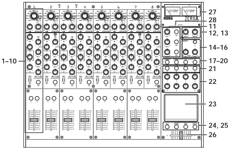
1. INPUT SELECTOR knob
Selects the input jack or FireWire audio signal that will be assigned to the mixer channel. With this knob in certain positions, the send knobs, pan knob, EQ knobs and/or faders will operate as MIDI controllers.
2. GAIN knob
Adjust the gain of the audio input assigned to the mixer channel.
TIP: If the MIC input level is too high, causing the sound to distort, press the rear panel MIC GAIN switch to change the mic preamp gain to LOW.
3. EQ SELECTOR knob
Selects the type of EQ. Switching the EQ type will change the function of the EQ knobs or vary the tonal character that occurs when adjusting each of the HI/MID/LO frequency bands.
4. EQ knobs
Normally, the HIGH, MID, and LO knobs boost or cut the sound in each frequency range. The MID-FREQ knob changes the center frequency of the MID range. Depending on the type of EQ selected in the previous step, the function of the knobs may change.
5. PAN knob
Adjusts the left/right audio balance.
6. SEND knobs
EXT1, EXT2: Adjusts the send levels to the effect processors connected to the EXT SEND1/2 jacks.
ZERO FX SEND: Adjusts the send level to the internal send effect (ZERO FX SEND).
7. SOLO/CUT switch
If you set this switch to the SOLO position, only the sound of that mixer channel will be sent from the master out. The sound of the other mixer channels will not be output.
TIP: More than one mixer channel can be set to SOLO.
If you hold the switch in the CUT position, the sound of that mixer channel will be muted.
TIP: You can't leave the switch set to the CUT position.
8. CUE button
When the CUE button is lit (ON), the prefader sound of that mixer channel will be sent to the CUE bus. By setting the MONITOR BAL knob toward CUE, you can monitor the sound of the CUE bus through headphones.
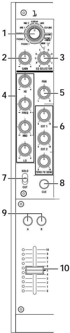
- A, B buttons
By pressing the A or B button you can assign this mixer channel to either side of the crossfader (crossfader channel A or B).
- Channel fader
Adjusts the level of the input audio assigned to this mixer channel.
- EXT1 knob, EXT2 knob, ZERO FX knob, CUE button
EXT1, EXT2: Adjust the return levels from the devices connected to the EXT1 RETURN jacks and EXT2 RETURN jacks.
ZERO FX SEND: Adjusts the return level from the internal send effect.
CUE: If you turn on the CUE button, the respective return signal will be sent to the CUE bus.
- BOOTH volume knob
Adjusts the output level from the BOOTH OUT jacks. This will output the same sound as the MASTER OUT jacks.
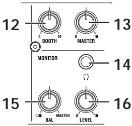
- MASTER volume knob
Adjusts the output level from the MASTER OUT jacks.
- Headphone jack
You can connect headphones to the headphone jack to monitor the audio of the MONITOR bus or CUE bus.
- MONITOR BAL knob
If this is turned toward CUE, the headphones will monitor the CUE bus. If this is turned toward MASTER, the headphones will monitor the MASTER OUT jacks.
- MONITOR LEVEL knob
Adjusts the headphone volume.
- SETUP button
Switches the LCD Display to the MAIN settings page, allowing you to edit or view various settings.
- BPM button
Accesses the BPM page in the LCD display, allowing you to turn the auto BPM detection on/off, select the source, and set the BPM manually.
- AUTO button
Turns auto BPM detection on (LED lit) or off (LED dark).
- TAP button
The timing interval at which you press this button is used to set the BPM value or as a guide for auto BPM detection.
- MIDI CONTROL BANK A, BANK B, BANK C, BANK D buttons
These buttons access the MIDI CONTROL BANK A, BANK B, BANK C, and BANK D pages. The eight push-knobs and the touch pad can be used as MIDI controllers to transmit the MIDI messages you assign for each bank.
- Push-knobs 1-8
These are controllers used to edit the parameters shown in the LCD display. When you're in the MIDI CONTROL page, these can also be used as controllers to transmit MIDI control messages.
- LCD display
This display features the TouchView system with a built-in touch panel. You can use it to select parameters shown in the LCD display, and also as a controller for touch-pad effects. When you're in the MIDI CONTROL page, you can also use the LCD panel as an X/Y pad MIDI controller.
- HOLD button
Holds the current value when you're operating an effect that uses the touchpad.

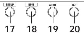
- CHANNEL, SEND, MASTER buttons
These buttons access pages where you can adjust the parameters for each effect.
CHANNEL: Accesses the channel effect, which can be inserted into a mixer channel. You can specify the mixer channel in which the channel effect will be inserted, and select an effect program.
SEND: Accesses the send effect, which is applied to the sound sent from each channel according to its effect send level setting. You can specify the return level that is sent back to the master bus.
MASTER: Accesses the master effect, which is applied to the sound of the master bus.
26. Crossfader
Crossfades the sounds that are assigned to the crossfader's channel A and channel B, and outputs the result to the master bus.
27. Master level meters
These are needle-style meters that indicates the output from master outs (Left and Right). If clipping occurs, the red LED will light; adjust the master out level so that this indicator does not light.
28. FireWire indicator
If the ZERO8 is connected to your computer via a FireWire cable, this indicator will light when the connection is detected.
Tip: Start up your host application after this indicator has lit.
Handling the LCD display
Never apply strong pressure to the LCD display or place heavy objects on it. Rough handling may crack or break the LCD display. Use only your fingertip to operate the display, since scraping or rubbing the surface may scratch it. If the display should require cleaning, wipe it gently with a soft dry cloth. Do not use an organic solvent such as thinner, since this may cause deformation.
Rear panel
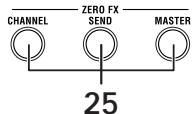
1. INPUT 1-8 (LINE) jacks
These are 1/4 TRS phone-type balanced input jacks.
Balanced TRS phone plug
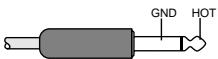
Unbalanced phone plug
2. INPUT 1-8 (CD/LINE) jacks
These are RCA-type unbalanced input jacks.
3. PHONO 1-3 jacks, GND terminal
These are phono input jacks for connecting turntables; a grounding terminal is also provided.
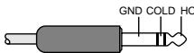
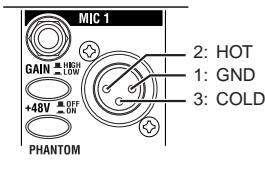
4. MIC1, MIC2 jacks
Two types of jacks are provided: TRS phone jacks and XLR jacks (with +48V phantom power supply).
If you connect the TRS phone jacks, the XLR jacks cannot be used.
5. MIC GAIN switches
48These set the mic preamp gain for the MIC 1 and MIC 2 jacks.
6. +48V PHANTOM switches
These turn phantom power on/off for the MIC 1 and MIC 2 jacks.
Phantom power is supplied to the balanced XLR jacks.
Note: If you connect or disconnect a condenser mic with the phantom power switch turned on, you risk damaging your equipment. Make sure that the phantom power switch is off before you connect or disconnect a condenser mic.
Caution: Never connect any device other than a condenser mic if the phantom power switch is on. Doing so may damage your equipment.
- GUITAR jack
Connect a guitar or bass guitar to this jack.
This is a 1/4 phone-type unbalanced input jack.
- EXT1 SEND, EXT2 SEND jacks
These jacks output the signal sent from each channel to the external sends. Connect these jacks to the inputs of your external effect processors.
- EXT1 RETURN,EXT2 RETURN jacks
The sound received at the RETURN jacks is mixed into the master bus. Connect the outputs of your external effect processors to these inputs.
- BOOTH OUT jacks
These outputs provide the same audio signal as the MASTER OUT jacks. You can use the BOOTH knob to adjust the BOOTH OUT jacks to a different level than MASTER OUT.
These are 1/4 TRS phone-type balance output jacks.
- MASTER OUT (XLR) jacks
These jacks output the audio of the master bus.
- MASTER OUT (TRS phone) jacks
These jacks output the audio of the master bus.
These are 1/4 TRS phone-type balance output jacks.
- MASTER OUT output level select switch
This switches the level of the TRS phone MASTER OUT jacks. Set this to the appropriate position for the equipment you've connected.
- FireWire connector
You can connect the ZERO8 to your computer and use it as an audio/ MIDI interface.
The two connectors operate in the same way. The connector not connected to your computer can be used for daisy-chain connections.
- DIGITAL OUT (coaxial) jack
This is a S/PDIF type digital output. It outputs the same audio as the MASTER OUT jacks in digital form.
You can connect this to the input jack of a consumer digital audio device.
It is an RCA phono-type coaxial jack.
- MIDI IN connector
This connector receives MIDI messages. Incoming MIDI messages can be sent to your computer via the FireWire connector.
- MIDI OUT connector
This connector re-transmits ("thru-es") the MIDI messages received from your computer via the FireWire connector. It also transmits MIDI messages produced by the ZERO8 itself.
- Power inlet
Connect the included power cable to this connector.
- Power switch
Turns the power on/off.
Connections and Operation
1. Preparations
Before you connect your equipment, you must turn off the power and disconnect the power cable from the AC outlet.
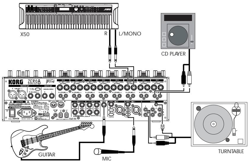
Connecting your output devices
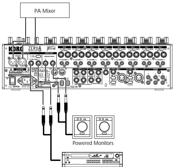
Master Recorder (Analog input)
Connecting your input devices
Use the appropriate jacks for the devices you're connecting.
Mic: MIC jacks (TRS phone jack or balanced XLR jack)
Guitar: GUITAR jack
Sampler, keyboard, etc.: LINE jacks (TRS phone-type balanced input jacks)
CD player: CD/LINE jacks (RCA type unbalanced input jacks)
Turntable: PHONO input jacks and ground connector
Turning the power on
When powering-on the ZERO8, you must use the following order.
- Connect the power cable.
Connect the included power cable to the power inlet. - Power-on the external equipment that's connected to the input jacks.
- Turn down the ZERO8's MASTER volume knob.
- Turn on the power switch located on the ZERO8's rear panel.
- Power-on your monitor amp and the amp that is connected to the MASTER OUT jacks.
Turning the power off
- Turn down the ZERO8's MASTER volume knob.
- Turn off the power of your monitor amp and the amp connected to the MASTER OUT jacks.
- Turn off the power switch located on the ZERO8's rear panel.
2. Using the mixer
Selecting the inputs
Here's how to assign a set of input jacks to a specific mixer channel.
- Use the top panel INPUT SELECTOR knob to select the desired input.
The knobs of each mixer channel for which you selected an audio input will light orange.
Knobs that are operating as MIDI controllers will light blue.
| PHONO 1, 2, 3 | Select the sound from the devices connected to the PHONO 1 jacks, PHONO 2 jacks, or PHONO 3 jacks respectively. |
| MIC 1, 2 | Select the sound from the devices connected to the MIC 1 jack or MIC 2 jack respectively. |
| GUITAR | Selects the sound from the device connected to the GUITAR jack. |
| LINE | Selects the sound of the device connected to the LINE jacks. |
| CD/LINE | Selects the sound of the device connected to the CD/LINE jacks. |
| FireWire AUDIO | Selects the sound from the computer connected to the FireWire connector. |
| FireWire AUDIO + MIDI | Selects the sound from the computer connected to the FireWire connector. In this case, the SEND (EXT 1, EXT 2, ZERO FX SEND) knobs and PAN knob will operate as MIDI controllers. |
| MIDI CONTROL | The controllers of the mixer channel will operate as MIDI controllers. |
TIP: If you've selected "FireWire AUDIO" or "FireWire AUDIO + MIDI," the output to the FireWire connector will be the pre-EQ signal of the source connected to the INPUT (LINE) jacks. If you've made settings in the SETTING page so that the output of the specified channel is other than "PRE EQ," "PRE FDR," or "POST FDR," those settings will take priority.
Adjusting the input levels
- Adjust the GAIN knob.
Adjust this knob so that the level indicator does not light red even when the maximum level is being input.
TIP: If you're using mic input and have connected a mic that has a high level, set the MIC GAIN switch to LOW.
Mixing the sounds
- Use the fader of each mixer channel to adjust its volume level.
- Use the PAN knob of each mixer channel to adjust its stereo position.
Crossfader
You can use the crossfader to crossfade between the sounds you've assigned to crossfader channels A and B. By using the crossfader you can perform DJ techniques such as switching instantly between the sounds of two channels or crossfading smoothly between them.
- For the mixer channel that you want to assign to crossfader channel A, press the A button to turn it on (the LED will light).
You may turn on the A button for more than one mixer channel if desired. -
For the mixer channel that you want to assign to crossfader channel B, press the B button to turn it on (the LED will light).
-
To cancel this setting, simply press a lit button once again.
If a mixer channel is not assigned to either channel A or B (i.e., if neither of these LEDs are lit), the sound of that mixer channel will be sent to the master bus without passing through the crossfader.
Master output / Booth output
The mixed sound is output from the MASTER OUT jacks and the BOOTH OUT jacks.
The same mixed sound is output from both sets of jacks, but you can use the MASTER knob and BOOTH knob to independently adjust each one to a different volume.
Adjusting the volume
- Use the MASTER volume knob to adjust the volume of the MASTER OUT jacks.
Adjust the volume to a level that does not cause the level meter to light red. - Use the BOOTH volume knob to adjust the volume of the BOOTH OUT jacks.
- Use the MONITOR LEVEL knob to adjust the volume of the headphones.
Monitoring
Connect headphones to the headphone jack so that you can refer to the mixed sound or the audio inputs.
CUE
This function lets you monitor your performance through headphones without outputting it from the MASTER OUT jacks. To monitor the sound of the CUE bus through headphones, turn the monitor section MONITOR BAL knob toward the CUE position. In this state, you can leave a fader lowered but turn CUE on and use your headphones to check the sound adjusted by EQ and the channel effect; then when you've adjusted the sound to your liking, raise the channel fader to output the sound from the master outputs.
Monitoring via CUE
By turning on the CUE button of a mixer channel, you can send its prefader sound to the CUE bus.
- Turn on the CUE button of the mixer channel you want to monitor.
- Use the MONITOR BAL knob to adjust the volume balance of the master output sound and the CUE bus sound.
Use the MONITOR LEVEL knob to adjust the overall volume.
Adjusting the effect levels
If you're using external effect processors, connect them to the EXT 1/2 SEND jacks and EXT 1/2 RETURN jacks.
- Use each mixer channel's EXT 1 and EXT 2 SEND knobs to adjust the send levels that are output to the SEND jacks.
Use the EXT 1 and EXT 2 RETURN knobs to adjust the return levels that are received from the RETURN 1 and RETURN 2 jacks.
- Use each mixer channel's ZERO FX SEND knobs to adjust the send level to the (built-in) send effect.
Use the ZERO FX SEND RETURN knob to adjust the return level from the send effect.
TIP: The CUE buttons for the EXT1, EXT 2, and ZERO FX returns introduce their respective signals to the CUE bus before the it passes through the return level knobs. Set the return level to zero and turn the CUE button on (lit). Now you'll be able to use headphones (set to CUE) to adjust the return sound. When you've adjusted the sound to your liking, raise the EXT1, EXT2 or ZERO FX return level knobs to send the signal to the master outputs.
3. Equalizer
Using the equalizer to adjust the sound
Traditionally, an equalizer (EQ) divides the sound into different frequency regions, allowing you to shape the tonal character of the sound by boosting or cutting the output of each region. In more modern applications, the EQ can be used as an effect, providing filter sweeps and isolator functions. The ZERO8 provides 11 different types of EQ.
- Use the EQ SELECTOR knob to select the equalizer type.
EQ type: These are a variety of EQ types with frequency responses suitable for different styles. Choose the type that's appropriate for your needs.
A ZERO EQ
B BOOST
C HYPED
DROUND-Q
E SLAMMING
ISOLATOR type: This is a -12dB/oct isolator. It divides the input sound into frequency regions, and allows you to individually cut the sound of each region. If you turn the knobs of all regions completely toward the left, the sound will disappear completely.
F ZERO ISOLATOR
G ZERO ISOLATOR WIDE DIVIDER
H ZERO ISOLATOR LOW
FILTER type: These are filter types in which HI is an LPF and LO is a HPF. Turning HI down (toward the left) will lower the cutoff frequency of the LPF. Turning LO down (toward the left) will raise the cutoff frequency. MID operates as a peaking EQ.
I ZERO FILTER
J ZERO FILTER DENSE
K ZERO FILTER SPIKY
- Use the EQ knobs to control the type of EQ you selected.
Adjust the three bands (HI/MID/LO) to obtain the desired tone. The MID-FREQ knob sets the center frequency of the MID region.
4. BPM system
In the ZERO8, the BPM (Beats Per Minute) setting is used as the master clock for MIDI and for effects that are synchronized to the BPM. The ZERO8 has an Auto BPM function that automatically detects the BPM from an audio input source. You can also set the BPM manually.
Setting the BPM manually
- Press the BPM button to access the BPM page.
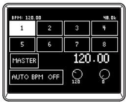
- Turn push-knobs 7 and 8 to set the desired BPM. By turning push-knob 8 you can adjust the BPM in fine steps of 0.01.
Setting the BPM using tap tempo
Press the TAP button at least three times to the beat of the song. The interval at which you pressed the button will be calculated, and specified as the BPM value.
Setting the BPM automatically
Here's how you can use the Auto BPM Counter to detect the BPM of a song that's being input.
- Press the BPM button to access the BPM page.
- In the LCD display, press 1-8 or the MASTER button to select the source whose BPM you want to detect.
If you select 1-8, the BPM will be detected from the sound of the corresponding channel.
If you select MASTER, the BPM will be detected from the mixed sound of all channels.
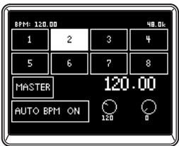
- In the LCD display, press the AUTO BPM button to turn AUTO BPM on; automatic BPM detection will begin.
If the BPM is detected incorrectly, you can leave AUTO BPM turned on, and press the TAP button at the beat of the song; the BPM will be automatically detected using your manual tapping as a guideline.
While AUTO BPM is on, the BPM will continue to be adjusted automatically even if the BPM of the audio input is changing.
TIP: By pressing the AUTO BPM button on the panel, you can turn AUTO BPM on/off even when you're not in the BPM page.
TIP: The BPM cannot be detected correctly for songs that don't have a definite beat.
5. Effects
The ZERO8 provides three independent effect processors: a Channel Effect which is used by inserting it into a mixer channel, a Send Effect which is applied to the sound sent by the send level knob of each mixer channel, and a Master Effect which is applied to the final stage of the master bus. To access the setting pages for each of these effects, press the CHANNEL, SEND, or MASTER buttons in the ZERO FX section.
Channel Effect
The channel effect is used by inserting it into a mixer channel, where it will process only the audio input of that channel.
To select the channel effect, press the CHANNEL button of the ZERO FX section to access the channel effect page. When the channel effect page is displayed, you can select the channel to which the effect will be applied.
TIP: The page that appears in the display will depend on the effect program.
Send Effect
This is a send/return type effect processor, which is applied to the sound sent by the send level knob of each mixer channel.
To select the send effect, press the SEND button of the ZERO FX section to access the send effect page.
TIP: The page that appears in the display will depend on the effect program.
Master Effect
The master effect is applied at the final stage to the overall mixed sound. To select the master effect, press the MASTER button of the ZERO FX section to access the master effect page.
TIP: The page that appears in the display will depend on the effect program.
Effect types
The effect setting page for each effect processor will appear as one of the following five types, depending on the effect program that is selected.
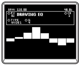
1: Touch effect 1 (eight-bar type)
This is an eight-bar type effect program page that you can control by drawing in the touch area in the lower part of the page. Use your finger to "draw" the gain curve for each band of the 8BAND EQ.
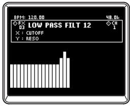
2: Touch effect 2 (filter type)
This is a filter-type effect program page where you can control the cutoff frequency by sliding your finger horizontally in the touch area in the lower part of the page. You can control the resonance by sliding your finger in the direction of the Y-axis.
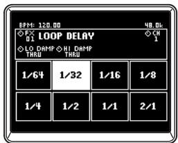
3: Touch effect 3 (eight-pad type)
This is a eight-pad type effect program page that you can control by pressing the eight pads shown in the touch area in the lower part of the page. By pressing the desired Beat setting of the LOOP DELAY effect, you can instantly switch the delay time's beat value.
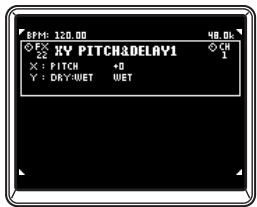
4: Touch effect 4 (touch pad type)
This is a touch-pad type effect program page in which the entire page is a touch area. Different effect parameters can be assigned to the X-axis and Y-axis, allowing you to control two parameters simultaneously with a single operation.
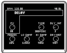
5: Knob control effect
This is an effect program page that does not use touch pad operations. You can control up to six effect parameters assigned to the push-knobs by turning the corresponding knob.
Operating the effects
Operating the touch effect types
In touch effect pages 2-4, you can turn the HOLD button on (LED lit) to maintain the current state of the effect.
HOLD on (LED lit): Hold will be enabled for the touch effect.
When you take your finger off the touch pad, the effect will remain in the state in which you had last been touching the pad.
HOLD off (LED dark): Hold will be disabled for the touch effect.
When you take your finger off the touch pad, the effect sound will be completely "dry."
Operating the knobs for each effect type
- For touch effect types 1-4, you can use the knobs to perform the following operations.
Knob 1: Selects the effect program
Knob 4: Selects the effect channel when using a channel effect
Knobs 5-8: Edit the effect parameters (the parameters that can be edited will depend on the effect program)
- For knob control effect type 5, you can use the knobs to perform the following operations.
Knob 1: Selects the effect program
Knob 2: Selects the effect channel when using a channel effect
Knobs 3-8: Edit the effect parameters (the parameters that can be edited will depend on the effect program)
FireWire interface functions
You can connect the ZERO8 to your computer via a FireWire cable and use it as an audio/MIDI interface.
Note: This device does not supply bus power.
Note: Do not simultaneously connect more than one computer to the ZERO8.
Note: If you are using a host application such as sequencing software, you'll need to make audio and MIDI device settings. For details, refer to the owner's manual of the software you're using.
Note: You must connect the ZERO8 to your computer using a FireWire cable and turn on the power before you start up your software. Don't disconnect the FireWire cable or power-off the ZERO8 while the software is running.
Note: If you're using the ZERO8 with Mac OS X, turn off the Sleep setting and power management settings.
Note: Each input/output device can be used with only one software application. Multi-client operation is not supported.
Note: Use the included CD-ROM to install the "KORG FireWire Audio/MIDI driver" into the computer you're using. (p.27)
1. FireWire audio interface
You can use the ZERO8 as an audio interface. This lets you send the ZERO8's audio inputs or mixed sound to your computer, and send the audio outputs from a host application on your computer to the ZERO8. Your FireWire-connected computer will detect the ZERO8 as an audio interface that provides a maximum of 16-in and 16-out audio streams.
Limitations for different sampling rates
If the ZERO8 is connected to your computer, you'll be able to change the sampling rate from the control panel of the host application or audio driver. The available number of effects and mixer channels will depend on the sampling rate you select.
44.1 kHz or 48 kHz: Eight stereo channels + the internal effects (ZERO FX CHANNEL, SEND, MASTER)
96 kHz: Eight stereo channels
Note: When operating at 96kHz , the internal effects (ZERO FX CHANNEL, SEND, MASTER) and the channel EQ for channels 5-8 will not be available. Nor will you be able to use the EXT1 or EXT2 RETURN jacks.
Note: When using the ZERO8 with Mac OS X
Depending on the system you're using, you may experience problems such as the operating system becoming unstable when you switch the sampling frequency.
If this occurs, you can start up as described below so that the ZERO8 will operate with a fixed sampling frequency. In this case, you won't be able to switch to another sampling frequency from the computer.
44.1 kHz: Turn on the power while holding down the mixer channel 1 Cue button.
48 kHz: Turn on the power while holding down the mixer channel 2 Cue button.
96 kHz: Turn on the power while holding down the mixer channel 3 Cue button.
In the Mac OS System Settings / Sound / Output dialog box, verify that the ZERO8 has disappeared from the list of sound output devices, and then turn the power on once again.
Depending on the type of computer you're using, starting up the computer with the ZERO8 already connected may cause operation to become unstable. In this case, connect the ZERO8 after the computer has started up.
Using the ZERO8 at the 192 kHz sampling rate
By starting up the ZERO8 in the special 192kHz audio mode, you can use it as a high-quality 24-bit/ 192kHz 8-in/8-out audio interface.
Note: When using Mac OS X, the 192 kHz sampling rate is not supported.
Starting up in 192 kHz audio mode
While holding down the SETUP button, turn on the power.
Note: If you start up in 192kHz audio mode, you won't be able to switch to other sampling rates (44.1 kHz, 48 kHz, 96 kHz). If you want to switch to a different sampling rate, you must turn off the power and then turn the power on again to start up in the normal way.
Limitations in 192 kHz audio mode
The specifications are limited as follows when operating in the special 192 kHz mode.
- Number of channels: Four stereo channels (8-in/8-out)
- Channel EQ: Not available
- EXT 1, EXT 2 SEND/RETURN: Not available
- Internal effects (CH, SEND, MASTER): Not available
Controller operation when in 192kHz audio mode
Channel controller
| CH1-4 | CH5-8 | |
| INPUT SELECTOR | Operates normally | Not available |
| GAIN | Operates normally | Not available |
| EQ SELECTOR | MIDI controller (transmits program change messages) | MIDI controller |
| HI | MIDI controller | MIDI controller |
| MID-FREQ | MIDI controller | MIDI controller |
| MID | MIDI controller | MIDI controller |
| LO | MIDI controller | MIDI controller |
| PAN | MIDI controller | MIDI controller |
| EXT1(SEND) | MIDI controller | MIDI controller |
| EXT2(SEND) | MIDI controller | MIDI controller |
| ZERO FX SEND | MIDI controller | MIDI controller |
| SOLO | Operates normally | MIDI controller |
| MUTE | Operates normally | MIDI controller |
| CUE | Operates normally | MIDI controller |
| A | Operates normally | MIDI controller |
| B | Operates normally | MIDI controller |
| CH FADER | Operates normally | MIDI controller |
Master controllers
| CROSSFADER | Operates normally |
| EXT1(RETURN) | Not available |
| EXT1(RETURN) CUE | Not available |
| EXT2(RETURN) | Not available |
| EXT2(RETURN)CUE | Not available |
| ZERO FX(RETURN) | Not available |
| ZERO FX(RETURN)CUE | Not available |
| MONITOR BAL | Operates normally |
| MONITOR LEVEL | Operates normally |
| BOOTH | Operates normally |
| MASTER | Operates normally |
2. FireWire MIDI interface
A MIDI device connected to the ZERO8's MIDI IN/OUT connectors can communicate with your computer via the FireWire connector.
About MIDI
MIDI stands for Musical Instrument Digital Interface, and is a world-wide standard that allows electronic musical instruments and computers to exchange a wide variety of performance-related information.
About the MIDI implementation chart
The owner's manual of each MIDI device includes a "MIDI implementation chart." This chart makes it easy to determine the types of MIDI messages that each device is able to transmit or receive. When using two MIDI devices, you can compare their MIDI implementation charts to see whether the messages transmitted by one device will be recognized by the other device. The MIDI implementation chart for this device is provided on the CD-ROM.
Note: Details of the MIDI functionality are provided in the MIDI implementation, which can be found on the included CD-ROM.
Using the ZERO8 as a MIDI controller
In addition to functioning as a mixer, the ZERO8 can also be used as a realtime controller that transmits MIDI messages to control an application on your computer or an external MIDI device such as a synthesizer.
Connecting to your computer
- Install the MIDI driver.
Use the included CD-ROM to install the "KORG FireWire Audio/MIDI driver" in your computer. (p.27)
TIP: If you're using a Macintosh, you don't need to install a driver.
- Use a FireWire cable to connect the ZERO8 to your computer.
- Make sure that your computer has detected the ZERO8.
- Start up your host application.
Note: When you connect the ZERO8 to your computer via a FireWire cable, it will be detected as a "3-in/3-out" MIDI interface. In this connection, "ZERO 1" is used to communicate between the ZERO8 and the included "ZERO Edit" editor software. "ZERO 2" is used to exchange MIDI messages between the ZERO8 and your MIDI host application such as a DAW. "ZERO 3" will operate as a MIDI interface used to exchange messages with an external MIDI device connected to the ZERO8's MIDI connectors. (p.20)
Note: Depending on the DAW or other MIDI host application you're using, the application may allocate all of the MIDI ports when it is started-up.
If you want to use this type of application at the same time as the "ZERO Edit" editor for the ZERO8, you must start up ZERO Edit first and allow it to detect and connect the "ZERO 2" MIDI port. Then start up your MIDI host application, and you'll be able to use the ZERO Edit software and your other application at the same time.
Using the controllers of the mixer channels as MIDI controllers
- Turn the INPUT SELECTOR knob to MIDI.
For the mixer channel you want to use as a controller, turn the INPUT SELECTOR knob to the MIDI position.
- When you operate the knobs/switches of the selected mixer channel, the MIDI control messages assigned to each controller will be transmitted.
At this time, the audio received at the LINE input jacks of the selected mixer channel will be output to the master bus. However, you won't be able to adjust the fader, EQ, or balance. Use the GAIN knob to adjust the volume.
- You can use the dedicated ZERO Edit editor software (or the System Setup>MAIN>CONTROL page) to change the MIDI messages assigned to each controller.
Using push-knobs 1-8 and the touch pad as MIDI controllers
You can use push-knobs 1-8 and the touch pad (LCD display) as MIDI controllers. Assignments for these controllers can be stored in the BANK 1-4 buttons, and recalled simply by pressing a button.
- Press the BANK 1 button to access the MIDI control bank page. The BANK 1 button will light.
- When you turn a push-knob 1-8, the MIDI message assigned to the respective encoder operation will be transmitted.
- When you push a push-knob 1-8, the MIDI message assigned to the respective switch operation will be transmitted.
- When you touch the LCD display (touch pad), the MIDI messages assigned to touch, X-axis, and Y-axis operations will be transmitted.
- You can use System Setup or the ZERO Edit application to change these MIDI messages.
- In the same way as for BANK 1, you can access the BANK 2 - 4 pages and transmit the MIDI messages that are assigned to the controllers in those banks.
FireWire Audio/MIDI device name list
MIDI Device
| PortNo | MIDI IN | MIDI OUT | Remarks |
| 1 | ZERO 1 | ZERO 1 | Only for ZERO Edit |
| 2 | ZERO 2 | ZERO 2 | Only for MIDI control-lers |
| 3 | ZERO 3 | ZERO 3 | For external MIDI IN/OUT connectors |
Note: Depending on the application you're using, the application may display its own port name rather than obtaining the name from the ZERO8.
Audio Device
| PortNo | Audio Input Audio Output | Corresponds to input jack Corresponds to output jack (factory settings*1) |
| 1 | ZERO 1L | CH 1 L |
| ZERO 1L | CH 1 L PRE EQ | |
| 2 | ZERO 1R | CH 1 R |
| ZERO 1R | CH 1 R PRE EQ | |
| 3 | ZERO 2L | CH 2 L |
| ZERO 2L | CH 2 L PRE EQ | |
| 4 | ZERO 2R | CH 2 R |
| ZERO 2R | CH 2 R PRE EQ | |
| 5 | ZERO 3L | CH 3 L |
| ZERO 3L | CH 3 L PRE EQ | |
| 6 | ZERO 3R | CH 3 R |
| ZERO 3R | CH 3 R PRE EQ | |
| 7 | ZERO 4L | CH 4 L |
| ZERO 4L | CH 4 L PRE EQ | |
| 8 | ZERO 4R | CH 4 R |
| ZERO 4R | CH 4 R PRE EQ | |
| 9 | ZERO 5L | CH 5 L |
| ZERO 5L | CH 5 L PRE EQ | |
| 10 | ZERO 5R | CH 5 R |
| ZERO 5R | CH 5 R PRE EQ | |
| 11 | ZERO 6L | CH 6 L |
| ZERO 6L | CH 6 L PRE EQ | |
| 12 | ZERO 6R | CH 6 R |
| ZERO 6R | CH 6 R PRE EQ | |
| 13 | ZERO 7L | CH 7 L |
| ZERO 7L | CH 7 L PRE EQ | |
| 14 | ZERO 7R | CH 7 R |
| ZERO 7R | CH 7 R PRE EQ | |
| 15 | ZERO 8L | CH 8 L |
| ZERO 8L | CH 8 L PRE EQ | |
| 16 | ZERO 8R | CH 8 R |
| ZERO 8R | CH 8 R PRE EQ | |
| 17 | ZERO INVALID AUDIO1 | --- |
| --- | --- | |
| 18 | ZERO INVALID AUDIO2 | --- |
| --- | --- |
Note: In some cases, audio input ports number 17 and number 18 on your computer may show a port name such as “ZERO INVALID AUDIO01, INVALID AUDIO02” or “INPUT17, INPUT18.” These audio input ports are invalid, and cannot be used.
Note: Depending on the application you're using, the application may display its own port name rather than obtaining the name from the ZERO8.
*1: The output locations of the audio output ports can be changed by using System Setup or the ZERO Edit application.
MIDI connections
In order to send and receive MIDI messages via the MIDI connectors, you will need to obtain commercially-available MIDI cables. Connect these cables between the ZERO8's MIDI connectors and the MIDI connectors of your external MIDI device.
MIDI IN connector: This receives MIDI messages from another MIDI device. Connect it to the MIDI OUT connector of your external device.
MIDI OUT connector: This transmits MIDI messages from the ZERO8.
Connect it to the MIDI IN connector of your external device.
System setup
Here you can specify the curve setting for each of the ZERO8's faders, and specify the MIDI messages that will be assigned to the various controllers.
1. Setup procedure
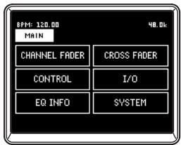
Press the SETUP button to access the SETTING MAIN page. Here you can make various settings for the ZERO8.
To save the setting parameters
When you modify the setting parameters, the SETUP button will blink. To save the setting parameters into the ZERO8's internal memory, press the SETUP button while it is blinking, or move to a page other than SETTING. If you turn off the power while the SETUP button is blinking, the changes you had made at that time will not be saved in internal memory.
2. Setup parameter guide
Selecting the fader curve
1. CHANNEL FADER
Here you can select or create the fader curve setting for each of the channel faders. You can choose one of several pre-loaded curves, or you can edit the Position and Curve parameters to create your own custom fader curve.
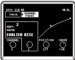
1: CHANNEL ....[1...8, ALL] Select the channel whose fader curve you want to set. By selecting "ALL" you can set all channels to the same fader curve.
2: NUMBER (NUM:) .... [1...8] Select one of the preset fader curves.
3: POSITION ......... [0...127] Specify the position at which the fader value will be at maximum.
4: CURVE .........[-64...+63] Specify the shape of the fader curve.
2. CROSS FADER
Here you can make fader curve settings for the cross fader. You can choose from several preloaded curves, or you can edit the Position and Curve parameters to create your own custom cross fader curves.
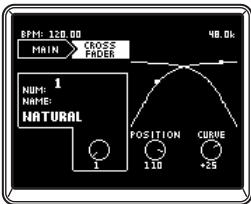
1: NUMBER (NUM:) .... [1...8] Select one of the preset crossfader curves.
2: POSITION ......... [0...127] Specify the position at which the crossfader value will be at maximum.
3: CURVE .........[-64...+63] Specify the shape of the crossfader curve.
MIDI control change message settings
3. CONTROL
Here you can make MIDI controller settings for when using push-knobs 1-8 as MIDI controllers. From the setting main page, press the CONTROLS button in the LCD display to access the CONTROLS page.
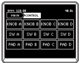
KNOBA-D
Specify the MIDI control messages that will be transmitted when you turn push-knobs 1-8 as encoders.
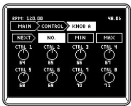
1: NEXT. Shows the next page.
2: NO. [0..127] Assigns a control change message to each push-knob.
3: MIN [0..127] Specifies the minimum control change value for each push-knob.
4: MAX [0..127] Specifies the maximum control change value for each push-knob.
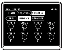
5: PREV . Shows the previous page.
6: MIDI CH [1...16] Specifies the MIDI channel for each push-knob.
7: BEHAVIOR......[ABS, REL] Specifies the operation mode for each push-knob.
ABS: The knob will operate in absolute value mode.
REL: The knob will operate in relative value (sign bit) mode. Turning the knob toward the right (when increasing) will transmit values of 1, 2, 3, ..., 64. Turning the knob toward the left (when decreasing) will transmit values of 65, 66, 67...127.
Note: If you select "REL" (relative value mode), make sure that your software supports this type of operation.
SWA-D
Here you can specify the MIDI control messages that will be transmitted when you press push-knobs 1-8 as switches.
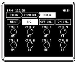
1: NEXT . Shows the next page.
2: NO. [0...127] Assigns a control change message or note number to each switch.
3: OFF VAL [0...127] Specify the value of the control change that will be transmitted when each switch is turned off. If you've selected "NOTE" as the type, this is fixed at note-off.
4: ON VAL [0...127] Specify the value of the control change that will be transmitted when each switch is turned on. If you've selected "NOTE" as the type, this specifies the note-on velocity value.
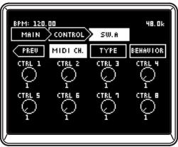
5: PREV Shows the previous page.
6: MIDI CH [1...16] Specifies the MIDI channel for each switch.
7: TYPE............[CC, NOTE] Specifies the MIDI message for each switch.
CC: A MIDI control change message will be transmitted when you operate the switch.
NOTE: A MIDI note message will be transmitted when you operate the switch. When you turn the switch on, a note-on message with the maximum velocity will be transmitted. When you turn the switch off, a note-off message will be transmitted.
8: BEHAVIOR.. [TOG, MOM] Specifies the operation mode for each switch.
TOG: Toggle operation. Each time you press the switch, it will alternately turn on or off.
MOM: Momentary operation. The switch will be on only while you are holding down it down, and will turn off when you release it.
PAD A-D
Here you can specify the MIDI control messages that are transmitted when you operate the touch pad.
You can separately specify messages for the X-axis, Y-axis, and touch.
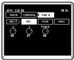
1: NEXT . Shows the next page.
2: NO. [0...127] Assigns a control change message to each controller.
3:MIN [0...127] For X and Y, this specifies the minimum value of the control change message for each controller.
TOUCH specifies the control change value
that will be transmitted when Off occurs. If you've selected "NOTE" as the type, this is fixed at note-off.
4:MAX [0...127] For X and Y, this specifies the maximum value of the control change message for each controller. TOUCH specifies the control change value that will be transmitted when Off occurs. If you've selected "NOTE" as the type, this specifies the note-on velocity value.
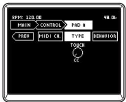
5: PREV . Shows the previous page.
6: MIDI CH [1...16] Specifies the MIDI channel of the touch panel. The MIDI channel you specify here is used for the X-axis, Y-axis, and Touch.
7: TYPE............[CC, NOTE] (Shown only for TOUCH) Specifies the MIDI message for Touch.
CC: A MIDI control change will be transmitted when you touch the pad.
NOTE: A MIDI note-on message will be transmitted when you touch the pad. When you touch the panel, a note-on message with the maximum velocity will be transmitted. When you release the panel, a note-off message will be transmitted.
8: BEHAVIOR... [TOG, MOM] (Shown only for TOUCH) Specifies the operation mode for Touch.
TOG: Each time you touch the pad, the On and Off states will alternate.
MOM: The On message will be transmitted when you touch the panel, and the Off message will be transmitted when you release it.
FireWire audio output settings
4. I/O
Here you can specify how audio signals received by the ZERO8 will be sent via FireWire. You can select the output sources that will be transmitted via FireWire. The ZERO8 can handle up to 16-in and 16-out audio channels. For the sixteen FireWire audio outputs, you can specify eight stereo channels as the output sources.
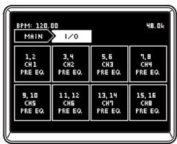
1: CH1...CH8 Select stereo channels 1-8 for the audio sent from the FireWire connector.
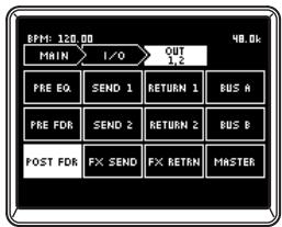
2: SOURCE Select the source of the audio sent via FireWire.
*PRE EQ: Selects the pre-EQ sound of the selected mixer channel.
*PRE FDR: Selects the pre-fader sound of the selected mixer channel.
*POST FDR: Selects the post-fader sound of the selected mixer channel.
SEND1: Selects the sound of the EXT1 SEND bus.
SEND2: Selects the sound of the EXT2 SEND2 bus.
FX SEND: Selects the sound of the ZERO FX SEND send bus.
RETURN1: Selects the sound of the EXT1 RETURN bus.
RETURN2: Selects the sound of the EXT2 RETURN bus.
FX RETURN: Selects the sound of the ZERO FX SEND return.
BUS A: Selects the sound of crossfader channel A.
BUS B: Selects the sound of crossfader channel B.
MASTER: Selects the sound of master out.
TIP: Sources marked with an asterisk* will output the sound of the INPUT (LINE) input if the FireWire audio input is selected in INPUT SELECT.
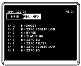
Viewing the EQ types
5. EQ INFO
Here you can view a list of EQ types selected for each channel. The LCD display will show the name of the EQ type selected for each channel.
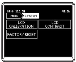
Adjusting the LCD display, and initializing the settings
6. SYSTEM
Here you can adjust the LCD display contrast, and calibrate the touch display. You can also restore the ZERO8 to its factory-set condition.
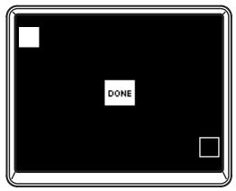
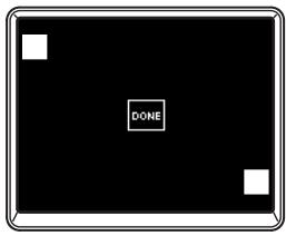
1. LCD CALIBRATION
This lets you calibrate the touch display. You should perform this operation when you notice that items in the LCD display are no longer lined up with the area of the touch panel normally used to select the items.
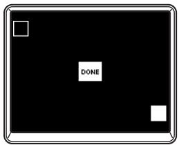
- Press the upper left corner of the touch display. The indicator will be highlighted when your touch is detected correctly.
- Press the lower right corner of the touch display. The indicator will be highlighted when your touch is detected correctly.
- Press the DONE button.
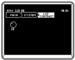
2. LCD CONTRAST
This lets you adjust the contrast of the LCD display.
Since the LCD display will appear differently depending on your viewing angle, you should adjust this when necessary.
Range: turn the [0 - 64] knob toward the left to make the characters darker, or toward the right to make them lighter.
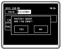
3. FACTORY RESET
This initializes the settings of the ZERO8 to their factory-set state.
- Press the FACTORY RESET button.
A dialog box will ask "ARE YOU SURE?"
- If you press "YES," the settings will be initialized to their factory-set state.
The operation will be cancelled if you press "NO."
Installing the software
Install the KORG FireWire Audio/MIDI driver and ZERO Edit software from the included CD-ROM into the computer to which you'll be connecting the ZERO8.
Contents of the CD-ROM
The included CD-ROM contains the following.
- ZERO Edit
- KORG FireWire Audio/MIDI driver
- ZERO Edit owner's manual (PDF)
- Software license agreement (RTF)
- MIDI implementation chart (PDF)
MIDI implementation
Please note before use
Copyright to all software included with this product is the property of Korg Corporation.
- The license agreement for the software included with this product is provided separately. You must read this license agreement before you install the software. Your installing the software will be taken to indicate your acceptance of this license agreement.
Operating requirements
Windows XP
Operating system: Microsoft Windows XP Home Edition / Professional Service Pack 2 or later
Computer: FireWire port is required
CPU: Pentium3 800 MHz or faster
Memory: 256 MB or more
Mac OS X
Operating system: Mac OS X 10.3.9 or later
Computer: FireWire port is required
CPU: PowerPC G3 800 MHz, PowerPC G4 733 MHz or better, or an Intel processor
Memory: 256 MB or more
1. Installing the driver and editor software in Windows XP
Note: You must have Administrator privileges in order to install or uninstall software in Windows XP. For details, please consult with your system administrator.
Note: You must use the ZERO4/ZERO8 application installer to install the KORG FireWire Audio/MIDI driver before you connect the ZERO8 to your computer via FireWire.
ZERO4/ZERO8 application installer
The ZERO4/ZERO8 application installer will automatically install the KORG FireWire Audio/MIDI driver and the ZERO Edit software into your computer.
- Insert the included CD-ROM into the CD-ROM drive of your computer.
Normally, the "ZERO4/ZERO8 Application Installer" will start up automatically.
If, due to settings on your computer, the installer does not start up automatically, double-click "KorgSetup.exe" on the CD-ROM.
- Following the instructions that appear in the screen, install the KORG FireWire Audio/MIDI driver and the ZERO Edit software.
Note: You must install the KORG FireWire Audio/MIDI driver if you want to use ZERO Edit via the FireWire port.
- When all of the selected software has been installed, exit the installer.
For details on the installation procedure, refer to the following section "Installing the KORG FireWire Audio/MIDI driver."
Installing the KORG FireWire Audio/MIDI driver
- Install the KORG FireWire Audio/MIDI driver as directed in the screen.
During the installation, a dialog box telling you that "... has not passed Windows logo testing" may appear, indicating that this driver does not have a digital signature. Simply click [Continue] to proceed.
Note: If you are unable to complete the installation, it may be that your computer has been set to prohibit installation of unsigned drivers. Check the settings of your computer as described in "Allowing installation of unsigned drivers."
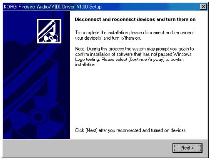
- When the following screen appears during the process of installing the KORG FireWire Audio/MIDI driver, connect the FireWire cable and power-on the ZERO8.
- When installation of the KORG FireWire Audio/MIDI driver has finished, exit the installer.
If you are asked to restart, choose [Yes] to restart your computer.
Setting up ZERO Edit
For details on how to set up and use ZERO Edit, refer to the "ZERO Edit operating manual."
Allowing installation of unsigned drivers
If your computer has been set to prohibit the installation of unsigned drivers, you won't be able to install the KORG FireWire Audio/MIDI driver. Proceed as follows to change the setting so that the driver can be installed.
- In the taskbar, click [Start] + [Control Panel] to open the control panel.
- In the control panel, double-click [System], and then click the [Hardware] tab.
- In the "Drivers" field, click [Driver Signing].
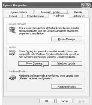
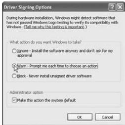
- In "What action do you want Windows to take?" choose [Ignore] or [Warn], and then click [OK].
If necessary, you can return this setting to its previous state after you've installed the KORG FireWire Audio/MIDI driver.
2. Installing the editor software in MacOS X
Installing the software
Here's how to start up the ZERO Edit installer and install the software.
TIP: The ZERO8 uses the standard MIDI driver provided by MacOS, so you don't have to install a MIDI driver.
- Insert the included CD-ROM into the CD-ROM drive of your computer.
- In the CD-ROM, double-click the software installer (.pkg) to it start.
The installer is located in the following folder.
"ZERO Edit" folder + ZERO Edit.pkg
- Follow the instructions in the screen to install the ZERO Edit software.
- When the software has been installed, exit the installer.
Setting up ZERO Edit
For details on how to set up and use ZERO Edit, refer to the "ZERO Edit operating manual."
Appendix
1. Troubleshooting
Power does not turn on
Is the power cable connected to an electrical outlet?
Is the rear panel power switch turned on?
No sound
□ Is the ZERO8 powered-on? Are the connected devices powered-on?
- Are the channel faders or the MONITOR LEVEL knob turned down?
Is the volume level of the channel turned down?
□ Is the SOLO/CUT switch set to CUT?
□ Is the GAIN knob raised to an appropriate level?
□ After connecting a device to an input jack, did you assign it correctly to the mixer channel?
Use the INPUT SELECTOR knobs to input the desired source into each mixer channel.
Make sure that audio is being input.
Use the level meter to verify that audio is being received into each mixer channel.
- Could you have selected a MIDI controller setting as the input selection?
Use the INPUT SELECTOR knob to select an input jack.
Excessive noise or distortion
□ Is the GAIN knob set appropriately? The sound will be distorted if the TRIM knob is set too high, and there will be excessive noise if it is set too low.
To obtain the best sound quality, the GAIN knobs for the GUITAR, MIC, and INPUT 1-INPUT 8 jacks should be adjusted as high as possible without allowing the level meter to light red.
Are you be using an effect?
Some of the effects intentionally add distortion or noise. Check whether distortion or noise occurs even if you're not using an effect.
If the sound is distorting at the EQ, make the following adjustment.
Adjust the gain value of the EQ.
Channel effect is not applied
Have you assigned the channel effect to the correct mixer channel?
Check the channel to which you assigned the effect.
Send effect is not applied
□ Is the send level for ZERO FX SEND set to 0 or near 0?
Raise the send level.
□ Is the return level for ZERO FX SEND set to 0 or near 0?
Raise the return level.
MIDI
MIDI sequencer will not synchronize / MIDI control does not work
Are the MIDI cables connected correctly?
Could a MIDI cable be broken?
- Are the synchronization-related settings of your MIDI sequencer correct?
Refer to the owner's manual for your MIDI sequencer.
Can't control via MIDI
□ Is the device receiving the control change set to receive MIDI channels 1-16?
Crossfader or MIDI controller operates incorrectly, or the touch panel operates incorrectly or fails to operate
□ You may be able to solve the problem by returning the system to the factory-set condition.
To return the system to the factory settings, hold down the following buttons while you turn on the power.
While holding down the mixer channel 7 Cue button and the mixer channel 8 Cue button, turn on the power.
FireWire
The computer does not detect the ZERO8
Is the FireWire cable connected correctly?
It is possible that the operating system of your computer has become unstable. Power-off your computer and the ZERO8, and then turn the power back on again.
An error occurs when you disconnect from the computer
- Never disconnect the ZERO8 from the computer while your host application is in use.
While connected, you are asked to install software or a device driver
- Does the operating system version of your computer support the ZERO8?
Starting up ZERO Edit or transferring MIDI is sometimes unsuccessful
Noise or crackling occurs when recording or playing-back on the computer
- Are you using a USB-connected peripheral device? If you are using a USB peripheral device such as an external USB hard disk, communication errors may occur in FireWire MIDI transmission, or there may be crackles or noise in the sound during recording or playback. If this occurs, please disconnect any unnecessary peripheral equipment.
Are you using a wireless LAN? If you are using a wireless LAN, FireWire MIDI communication errors may occur, or there may be crackles or noise in the playback or recording. If this occurs, turn off your wireless LAN while using the ZERO8.
Driver-related problems
Can't install the KORG FireWire Audio/MIDI driver successfully
- Could another FireWire (IEEE1394) device be connected?
Disconnect all FireWire devices other than the ZERO8 from your computer when you perform the installation. If the ZERO8 is connected to an external FireWire hard disk, connect the ZERO8 directly to the FireWire connector (IEEE 1394 connector, iLink connector, DV connector) on the computer itself. - Could other software programs or resident software (such as anti-virus software) be running?
It may be impossible to perform the installation successfully if other programs are running. Exit all other programs before you begin the installation.
Can't record/play audio or MIDI. No sound is output.
Did you connect or disconnect the FireWire (IEEE 1394) cable or turn the ZERO8's power on/off while the software was running?
Exit all of your software; then turn the ZERO8's power off and on once again.
For some models of computer, starting up your computer with the ZERO8 already connected may cause operation to be unstable. In this case, start up your computer before you connect the ZERO8.
- Did your computer enter the Standby (Suspend) or Sleep mode?
After returning to normal operating mode, exit all software and power-cycle the ZERO8. Then start up your software again.
□ Is the KORG FireWire Audio/MIDI driver installed correctly?
In order to play back audio/MIDI using the ZERO8, you must install the KORG FireWire Audio/MIDI driver. For details on the installation, refer to "Installing the driver" (e3 p.27).
□ Are multiple software programs running?
Error messages may appear if multiple software programs are running simultaneously. In this case, you should exit the software you're not using. In Windows, closing the window of a program does not necessary exit the program; if the program is shown in the task bar, it is still running. You must close any unneeded programs shown in the taskbar.
Have you correctly specified the input/output devices you want to use?
Depending on the application you're using, you may need to make audio/MIDI device settings. Refer to the owner's manual of the application you're using, and specify the appropriate audio/MIDI devices.
Noise or clicks/pops are heard when you record or play back on your computer
Have you connected more than one ZERO4/ZERO8 unit, other audio interface, or other audio device to your computer?
Have you connected the ZERO8 to a FireWire (IEEE 1394) repeater hub?
Connect only a single ZERO8 to your computer, and check whether the noise disappears. Depending on your system, noise may occur if numerous audio devices are connected to your computer. If so, connect only the ZERO8 to your computer.
□ Are you using a FireWire device other than the ZERO8?
If the ZERO8 is connected to an external FireWire hard disk, you should re-connect the ZERO8 directly to the FireWire connector (IEEE 1394 connector, iLink connector, DV connector) of your computer. Turn off the power of all FireWire devices other than the ZERO8.
While using the ZERO8, could you have performed a task that involved a heavy processing load, such as accessing the CD-ROM drive or the network?
The system may not work correctly if a heavy processing load occurs while using the ZERO8. Stop recording/playback, and then resume recording/playback. If you are still unable to play/record correctly, exit all software and reconnect the ZERO8.
If you're using Windows, you may be able to solve the problem by adjusting the buffer size in the KORG FireWire Audio/MIDI driver settings.
2. Error messages
MIDI RX BUSY
A large amount of incoming MIDI data is being processed. While this message is displayed, the faders and knobs will be temporarily inoperable. Please wait for this message to disappear before you continue operation.
MIDI RX ERROR
More MIDI data was received in a short time than could be processed successfully. Please avoid sending unnecessary MIDI data.
SYSTEMERROR???
This message will appear if the ZERO8 has a problem or malfunction. If this message appears, make a note of the ??? text, and contact customer service.
3. Specifications
Display: 160 × 104 pixel, LCD with backlight and touch panel
Power supply: AC Local Voltage
Power consumption: 52W
Dimensions: 450mm (W) x 371 mm (D) x 125 mm (H) /
17.72" (W) x 14.61" (D) x 4.92" (H)
Weight: 7.3kg / 16.09 lbs.
Main specifications
INPUT (TRS) OUTPUT (MASTER)
Frequency response: 10Hz - 20kHz + 1 dB, -2dB @ fs 44.1 kHz
10Hz - 21kHz± 1 dB @ fs 48kHz
10Hz - 40kHz± 1 dB@fs 96~kHz
15 Hz-50 kHz ±1 dB @ fs 192 kHz
S/N: 93 dB (typical) @IHF-A
THD + N .. 0.02% (typical) INPUT: +22 dBu @ GAIN = 0 dB
A/D conversion: 24-bit 64-times oversampling
D/A conversion: 24-bit 128-times oversampling
Sampling frequency (fs): Internal 44.1kHz 48 kHz,96 kHz,192 kHz
Analog and digital input/output specifications
INPUT 1-8 (LINE, CD/LINE)
Connectors: 1 / 4'' TRS phone jacks (balanced) L/R,
RCA jacks L/R
Input impedance: 10k
Nominal level: TRS: +4 dBu @ GAIN = 0 dB (GAIN = - dB-0dB)
RCA: -10 dBu @ GAIN = 0 dB (GAIN = -∞dB--+6dB)
Maximam level: TRS: +22 dBu @ GAIN = 0 dB (GAIN = -∞dB-0dB)
RCA: +8 dBu @ GAIN = 0 dB (GAIN = -∞dB - +6dB)
Source impedance: 600Ω
PHONO 1-3
Connectors: RCA jacks L/R
Input impedance: 50k
Nominal level: -44 dBu @ 1 Khz, GAIN = 0 dB (GAIN = -∞dB + 6dB),
RIAA compliant
MIC 1, 2 INPUT
Connectors: XLR-3-31 type (+48V phantom power, with switch) 1 / 4'' TRS phone jack (balanced)
Input impedance: 3k /XLR,5k /TRS
Nominal level: Hi: -60 dB @ GAIN = 0 dB (GAIN = -∞dB-0dB)
Low: -40 dBu @ GAIN = 0 dB (GAIN = -∞ dB-0 dB)
Maximam level: Hi: -42 dBu @ GAIN = 0 dB (GAIN = -∞dB-0dB)
Low: -22 dBu @ GAIN = 0 dB (GAIN = -∞dB-0dB)
Source impedance: 600Ω
GUITAR INPUT
Connector: 1 / 4'' phone jack (unbalanced)
Input impedance: 1 MΩ
Nominal level: -6 dB@ GAIN = 0dB (GAIN = -∞dB-+6dB)
Maximam level: +12dB @ GAIN = 0dB (GAIN = - dB + + 6dB )
Source impedance: 600Ω
MASTER OUTPUT L/R
Connector: XLR-3-32 type L/R
Output impedance: 150
Nominal level: +4dBu
Maximam level: +22dBu
Load impedance: greater than 10k
BOOTH OUTPUT L/R
Connector: 1 / 4^ TRS phone jacks (balanced) L/R
Output impedance: 150
Nominal level: +4dBu
Maximam level: +22dBu
Load impedance: greater than 10k
EXTSEND1,2L/R
Connector: 1 / 4" TRS phone jacks (balanced) L/R
Output impedance: 150
Nominal level: +4dBu
Maximam level: +22dBu
Load impedance: greater than 10k
EXT RETURN 1, 2 L/R
Connectors: 1/4" TRS phone jacks (balanced) L/R
Input impedance: 10k
Nominal level: +4dBu
Maximam level: +22dBu
Source impedance: 600Ω
PHONES OUTPUT
Connector: 1 / 4 stereo phone jack
Output impedance: 100
Maximum level: 80mW + 80mW @ 32 Ω
S/P DIF OUTPUT
Connector: coaxial
Format: 24-bit S/P DIF (IEC60958)
FireWire
Connector: IEEE 1394 6-pin connector
Format: IEEE1394a
MIDI INPUT/OUTPUT
Connector: DIN 5-pin x2
Included items
Power cable
Owner's manual
CD-ROM
- Appearance and specifications of this product are subject to change without notice.
WARNING: TO REDUCE THE RISK OF FIRE OR ELECTRIC SHOCK DO NOT EXPOSE THIS PRODUCT TO RAIN OR MOISTURE.


m = 311 ;
- Prises EXT1 RETURN,EXT2 RETURN
INPUT 1~8 (LINE, CD/LINE)
| Prises: | Jacks TRS 6,35 (symétriques) L/R, prises RCA L/R |
| Impédance d'entrée: | 10 kΩ |
| Niveau nominal: | TRS: +4 dBu @ GAIN = 0 dB (GAIN = -∞ ~ 0 dB) RCA: -10 dBu @ GAIN = 0 dB (GAIN = -∞ ~ +6 dB) |
| Niveau maximum: | TRS: +22 dBu @ GAIN = 0 dB (GAIN = -∞ ~ 0 dB) RCA: +8 dBu @ GAIN = 0 dB (GAIN = -∞ ~ +6 dB) |
| Impédance de source: | 600 Ω |
PHONO 1~3
Prises: Prises RCA
Impedance d'entree: 50k
Niveau maximum: -44 dBu @ 1 Hz, GAIN = 0 dB (GAIN = -∞ ~ +6
dB), Conforme PHONO RIAA
MIC 1, 2 INPUT
LOW: -40 dBu @ GAIN = 0 dB (GAIN = -∞ ~ 0 dB)
Niveau maximum: HIGH: -42 dBu @ GAIN = 0 dB (GAIN = -∞ ~ 0 dB)
LOW: -22 dBu @ GAIN = 0 dB (GAIN = -∞ ~ 0 dB)
Impedance de source: 600Ω
GUITAR INPUT
TO REDUCE THE RISK OF FIRE OR ELECTRIC SHOCK DO NOT EXPOSE THIS PRODUCT TO RAIN OR MOISTURE.
CAUTION
RISK OF ELECTRIC SHOCK DO NOT OPEN

AVERTISSEMENT:
RISQUE DE CHOC ÉLECTRIQUE—NE PAS OUVRIR.
注意
感電の恐れあ、�はトをあけるな
10 Hz-21 kHz ±1 dB @ fs 48 kHz
10 Hz-40 kHz ±1 dB @ fs 96 kHz
15 Hz-50 kHz ±1 dB @ fs 192 kHz
Signal-/Rauschabstand: 93 dB (Standard) @IHF-A
Klrr + N: 0,02% (Standard) INPUT: +22 dBu @ GAIN = 0 dB
Samplingfrequenz (fs): Intern 44,1 kHz, 48 kHz, 96 kHz, 192 kHz
LOW: -40 dBu @ GAIN = 0 dB (GAIN = -∞ - 0 dB)
Maximalpegel: HIGH: -42 dBu @ GAIN = 0 dB (GAIN = -∞-0 dB)
LOW: -22 dBu @ GAIN = 0 dB (GAIN = -∞ - 0 dB)
Quellimpedanz: 600Ω
GUITAR INPUT
| 0 | NO EFFECT | 31 | XY LFO LPF24 |
| 1 | LOOP DELAY | 32 | XY LFO HPF |
| 2 | DRAWING EQ | 33 | XY LFO BPF |
| 3 | XY LPF12 | 34 | XY LFO BPF+ |
| 4 | XY LPF18 | 35 | XY LFO HPF+&DLY |
| 5 | XY LPF24 | 36 | XY CHORUS |
| 6 | XY LPF30 | 37 | XY FLANGER |
| 7 | XY HPF | 38 | XY FLANGER&LPF |
| 8 | XY BPF | 39 | XY FLANGER&DELAY |
| 9 | XY BPF+ | 40 | XY PHASER |
| 10 | XY LPF12&DELAY | 41 | XY PHASER&DELAY |
| 11 | XY LPF24&DELAY | 42 | XY LFO WAH |
| 12 | XY HPF&DELAY | 43 | XY DIST&LFO WAH |
| 13 | XY BPF&DELAY | 44 | XY LFO DIGI TALK |
| 14 | XY BPF+&DELAY | 45 | XY AUTO PAN |
| 15 | XY JET | 46 | XY SLICER |
| 16 | XY MANUAL PHASER | 47 | XY SLICER&LPF |
| 17 | XY MANUAL WAH | 48 | XY SLICER&HPF |
| 18 | XY RIMG MOD | 49 | XY DELAY |
| 19 | XY DIGI TALK | 50 | XY BPM DELAY |
| 20 | XY PITCH SHIFT | 51 | XY NO FEEDBK DLY |
| 21 | XY PITCH FINE | 52 | XY LOW CUT DELAY |
| 22 | XY PITCH&DELAY1 | 53 | XY MULTI TAP DLY |
| 23 | XY PITCH&DELAY2 | 54 | XY CHORUS DELAY |
| 24 | XY DISTORTION | 55 | XY TAPE ECHO |
| 25 | XY DIST&MANU WAH | 56 | XY Dub Echo |
| 26 | XY DECIMATOR | 57 | XY FEEDBACK DELAY |
| 27 | XY DECIMA&LPF | 58 | XY REVERB HALL |
| 28 | XY COMPRESSOR | 59 | XY REVERB S-HALL |
| 29 | XY LFO LPF12 | 60 | XY REVERB D-PLAT |
| 30 | XY LFO LPF18 | 61 | XY REVERB W-PLAT |
CHANNEL Effect: 0-111
SEND Effect: 0,73-111
MASTER Effect: 0-111
92 DECIMATOR
93 DECIMATOR&COMP
94 DECIMATOR&LPF
95 TUBE PRE
96 COMP
97 FAT COMP
98 LIMITER
99 DELAY
100 BPM DELAY
101 MULTITAP DELAY
102 BPM MULTI TAP DELAY
103 CHORUS&DELAY
104 TAPE ECHO
105 REVERB HALL
106 REVERB SMOOTHHAL
107 REVERB DRY PLATE
108 REVERB WET PLATE
109 GRAIN SHIFTER
110 BPM GRAIN
111 LOOPER
Block Diagram
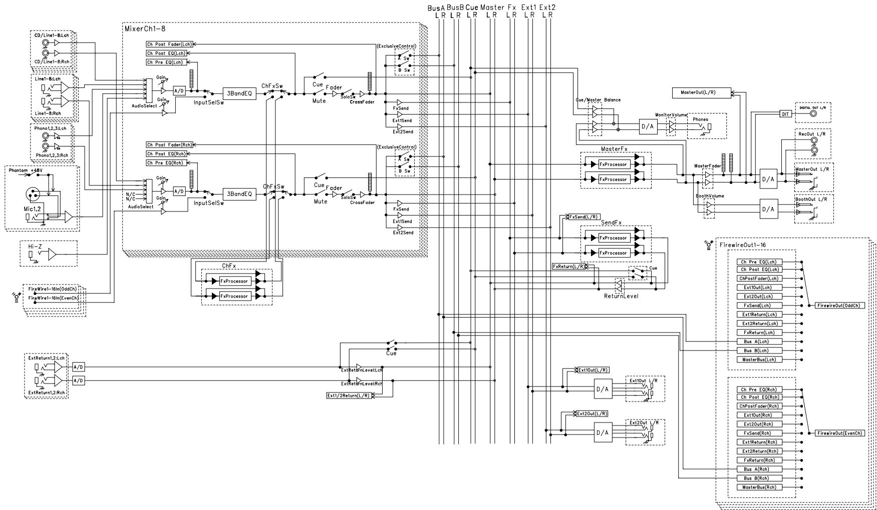
IMPORTANT NOTICE TO CONSUMERS
This product has been manufactured according to strict specifications and voltage requirements that are applicable in the country in which it is intended that this product should be used. If you have purchased this product via the internet, through mail order, and/or via a telephone sale, you must verify that this product is intended to be used in the country in which you reside.
WARNING: Use of this product in any country other than that for which it is intended could be dangerous and could invalidate the manufacturer's or distributor's warranty.
Please also retain your receipt as proof of purchase otherwise your product may be disqualified from the manufacturer's or distributor's warranty.
REMARQUE IMPORTANTE POUR LES CLIENTS
- IMPORTANT SAFETY INSTRUCTIONS
- WARNING:
- CAUTION
- AVERTISSEMENT:
- 注意
- THE FCC REGULATION WARNING (for U.S.A.)
- Notice regarding disposal
- Table of Contents
- Introduction 5
- Connections and Operation 10
- FireWire interface functions 17
- System setup 22
- Installing the software 27
- Appendix 30
- Introduction
- Main features
- Eight-channel stereo digital mixer
- FireWire audio/MIDI interface
- Flexible channel selection
- EQ type selector
- Fader/crossfader curve controller
- Auto BPM detection
- Push-knob MIDI controller
- Touch-panel LCD
- Mic preamps
- Parts of the ZERO8
- Top panel
- INPUT SELECTOR knob
- GAIN knob
- EQ SELECTOR knob
- EQ knobs
- PAN knob
- SEND knobs
- SOLO/CUT switch
- CUE button
- Crossfader
- Master level meters
- FireWire indicator
- Handling the LCD display
- Rear panel
- INPUT 1-8 (LINE) jacks
- INPUT 1-8 (CD/LINE) jacks
- PHONO 1-3 jacks, GND terminal
- MIC1, MIC2 jacks
- MIC GAIN switches
- +48V PHANTOM switches
- Connections and Operation
- Preparations
- Connecting your output devices
- Connecting your input devices
- Turning the power on
- Turning the power off
- Using the mixer
- Selecting the inputs
- Adjusting the input levels
- Mixing the sounds
- Crossfader
- Master output / Booth output
- Adjusting the volume
- Monitoring
- CUE
- Monitoring via CUE
- Adjusting the effect levels
- Equalizer
- Using the equalizer to adjust the sound
- BPM system
- Setting the BPM manually
- Setting the BPM using tap tempo
- Setting the BPM automatically
- Effects
- Channel Effect
- Send Effect
- Master Effect
- Effect types
- 1: Touch effect 1 (eight-bar type)
- 2: Touch effect 2 (filter type)
- 3: Touch effect 3 (eight-pad type)
- 4: Touch effect 4 (touch pad type)
- 5: Knob control effect
- Operating the effects
- Operating the touch effect types
- Operating the knobs for each effect type
- FireWire interface functions
- FireWire audio interface
- Limitations for different sampling rates
- Using the ZERO8 at the 192 kHz sampling rate
- Starting up in 192 kHz audio mode
- Limitations in 192 kHz audio mode
- Controller operation when in 192kHz audio mode
- FireWire MIDI interface
- About MIDI
- About the MIDI implementation chart
- Using the ZERO8 as a MIDI controller
- Connecting to your computer
- Using the controllers of the mixer channels as MIDI controllers
- Using push-knobs 1-8 and the touch pad as MIDI controllers
- FireWire Audio/MIDI device name list
- MIDI connections
- System setup
- Setup procedure
- To save the setting parameters
- Setup parameter guide
- Selecting the fader curve
- CHANNEL FADER
- CROSS FADER
- MIDI control change message settings
- CONTROL
- KNOBA-D
- SWA-D
- PAD A-D
- FireWire audio output settings
- I/O
- Viewing the EQ types
- EQ INFO
- Adjusting the LCD display, and initializing the settings
- SYSTEM
- LCD CALIBRATION
- LCD CONTRAST
- FACTORY RESET
- Installing the software
- Contents of the CD-ROM
- Please note before use
- Operating requirements
- Windows XP
- Mac OS X
- Installing the driver and editor software in Windows XP
- ZERO4/ZERO8 application installer
- Installing the KORG FireWire Audio/MIDI driver
- Setting up ZERO Edit
- Allowing installation of unsigned drivers
- Installing the editor software in MacOS X
- Appendix
- Troubleshooting
- Power does not turn on
- No sound
- Excessive noise or distortion
- Channel effect is not applied
- Send effect is not applied
- MIDI
- FireWire
- Driver-related problems
- Can't record/play audio or MIDI. No sound is output.
- Noise or clicks/pops are heard when you record or play back on your computer
- Error messages
- MIDI RX BUSY
- MIDI RX ERROR
- SYSTEMERROR???
- Specifications
- Main specifications
- Analog and digital input/output specifications
- INPUT 1-8 (LINE, CD/LINE)
- PHONO 1-3
- MIC 1, 2 INPUT
- GUITAR INPUT
- MASTER OUTPUT L/R
- BOOTH OUTPUT L/R
- EXTSEND1,2L/R
- EXT RETURN 1, 2 L/R
- PHONES OUTPUT
- S/P DIF OUTPUT
- MIDI INPUT/OUTPUT
- Included items
- WARNING: TO REDUCE THE RISK OF FIRE OR ELECTRIC SHOCK DO NOT EXPOSE THIS PRODUCT TO RAIN OR MOISTURE.
- INPUT 1~8 (LINE, CD/LINE)
- PHONO 1~3
- Block Diagram
- IMPORTANT NOTICE TO CONSUMERS
- REMARQUE IMPORTANTE POUR LES CLIENTS
Brand : KORG
Model : ZERO 8
Category : Mixer