N-com B602 X - Headset Nolan - Free user manual and instructions
Find the device manual for free N-com B602 X Nolan in PDF.


| Product Type | Modular motorcycle helmet with integrated communication system |
| Brand | Nolan |
| Model | N-com B602 X |
| Available Sizes | XS, S, M, L, XL, XXL |
| Approximate Weight | 1,500 g (depending on size) |
| Power Supply | Rechargeable lithium-ion battery (USB-C) |
| Battery Life | Up to 12 hours in communication |
| Main Functions | Bluetooth 5.0, intercom up to 4 riders, GPS, FM radio, voice commands |
| Shell Material | Lexan polycarbonate |
| Approval | ECE 22.05 / 22.06 |
| Maintenance and Cleaning | Clean the visor with a microfiber cloth, interior padding is washable |
| Safety | Scratch-resistant visor, emergency release system, double D-ring |
| Spare Parts Available | Visors, interior padding, battery, sun shield |
| Repairability | Spare parts available through the Nolan network |
| Warranty | 2 years |
| Box Contents | Helmet, N-com system, clear visor, sun shield, USB cable, carrying bag |
Frequently Asked Questions - N-com B602 X Nolan
User questions about N-com B602 X Nolan
0 question about this device. Answer the ones you know or ask your own.
Ask a new question about this device
Download the instructions for your Headset in PDF format for free! Find your manual N-com B602 X - Nolan and take your electronic device back in hand. On this page are published all the documents necessary for the use of your device. N-com B602 X by Nolan.
USER MANUAL N-com B602 X Nolan
Fig. 1

Fig. 2

Fig. 3
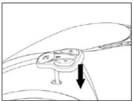
Fig. 4

Fig. 5
Fig. 6

Fig. 7
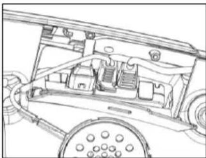
Fig. 8
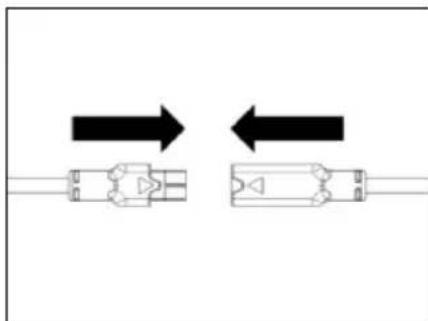
Fig. 9
Fig. 10

Fig. 11
Fig. 12
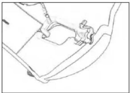
Fig. 13
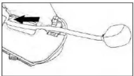
Fig. 14

Fig. 15
SOLO PER CASCHI X-903, X-552
Fig. 16

Fig. 17

Fig. 17B
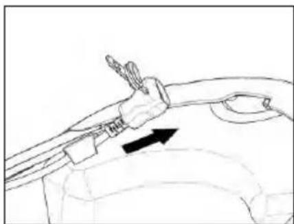
Fig. 18

Fig. 19
Fig. 20 - CASCO X-1005

Fig. 21 - CASCO X-903
Fig. 22

Fig. 23
Fig. 24
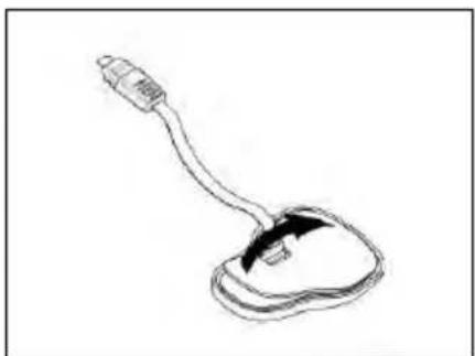
Fig. 25

Fig. 26

Fig. 27
Fig. 28

Fig. 29

Fig. 30
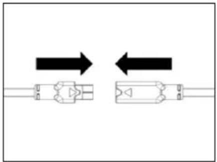
Fig. 31
Fig. 32

Fig. 33
Fig. 34
Fig. 35

Fig. 36

Fig. 37
Fig. 38

Fig. 39
Fig. 40

Fig. 41
Fig. 42
This device complies with Part 15 of the FCC Rules. Operation is subject to the following two conditions: (1) this device may not cause harmful interference, and (2) this device must accept any interference received, including interference that may cause undesired operation of the device.
Changes or modifications not expressly approved by the party responsible for compliance could void the user's authority to operate the equipment.
NOTE: The manufacturer is not responsible for any radio or TV interference caused by unauthorized modifications to this equipment. Such modifications could void the user's authority to operate the equipment.
This equipment has been tested and found to comply with the limits for a Class B digital device, pursuant to part 15 of the FCC rules. These limits are designed to provide reasonable protection against harmful interference in a residential installation. This equipment generates, uses and can radiate radio frequency energy and, if not installed and used in accordance with the instructions, may cause harmful interference to radio communications. However, there is no guarantee that interference will not occur in a particular installation.
This model meets the government's requirements for exposure to radio waves. Your wireless device is a radio transmitter and receiver. It is designed and manufactured not to exceed limits for exposure to radio frequency (RF) energy set by the Federal Communications Commission (FCC) of the U.S. Government and by the Canadian regulatory authorities.
The exposure standard for wireless mobile devices employs a unit of measurement known as the Specific Absorption Rate, or SAR. The SAR limit set by the FCC and by the Canadian regulatory authorities is 1.6 W/kg.1.
For Canada market only:
This EUT is compliant with SAR for general population/uncontrolled exposure limits in IC RSS-247. The N-Com electronic device is positioned on a minimum distance of - see the table below - from the head of the user, therefore no SAR test have been conducted on the product.
| N-COM SYSTEM | DISTANCE FROM THE HEAD |
| B902L R/B902 R | 30.00 mm |
| B602 R | 30.63 mm |
| B101 R | 30.63 mm |
| B902 X | 32.50 mm |
| B602 X | 34.50 mm |
POUR LE MARCHE US ET CANADIEN UNIQUEMENT: MISE EN GARDE SPECIALE
USER INSTRUCTIONS AND SAFETY
Thank you for buying an N-Com product.
N-Com B602 was made using the most advanced technology and top-quality materials. Long-running tests and thorough system development have made it possible to achieve the highest audio quality.
Please read the user instructions before using the product.
For further information on the B602 and video tutorials and information on installing the latest Firmware version, please visit www.n-com.it

MANUALS

TUTORIALS
The Bluetooth® word mark and logos are registered trademarks owned by Bluetooth SIG, Inc.; any use of such marks by N-Com is under license. Other trademarks and trade names are those of their respective owners.
Contents
1. WARNINGS AND SAFETY 5
1.1.Road safety 5
1.2.Switching on the system in safe environments 5
1.3.Interferences .... 5
1.4. Appropriate use....5
1.5.Qualified personnel 6
1.6.Accessories and batteries....6
1.7.Disposal....6
2. CONTENT OF THE PACKAGING 7
3. INSTALLATION ON THE X-1005, X-903, X-552 HELMET 8
3.1.Preliminary operations....8
3.2.Installing the system in the X-1005, X-903, X-552 helmets....8
3.3.Microphone positioning 10
3.4.Repositioning the padding 11
4. INSTALLATION ON THE X-LITE HELMETS....12
4.1.Preliminary operations....12
4.2.Installing the system in the helmet....12
4.3.Microphone positioning 14
4.4.Repositioning the padding 15
5. REMOVING THE SYSTEM....15
6. BASIC FUNCTIONS....16
6.1.Complete Mode and Simple Mode....16
6.2.Volume adjustment 16
6.3.Auto Off function....17
6.4.Multi-language voice messages....17
6.5.N-Com EASYSET 18
6.6.Updating the firmware 18
7. PAIRING MODE 19
7.1.Pairing Menu....19
8. CONFIGURATION MENU....20
9. MOBILE PHONE / MP3 PLAYER PAIRING....21
10. SECOND MOBILE PHONE PAIRING....21
11. MOBILE PHONE 22
11.1.Speed dial....22
11.2.Conference call function....23
11.3.Smart Navi System....23
12. MUSIC VIA BLUETOOTH....24
12.1.Sharing music via Bluetooth (A2DP Sharing)....24
13. GPS PAIRING....24
14. INTERCOM RIDER-PASSENGER....25
14.1.N-Com "600"/"800"/"900" Series Intercom pairing 25
14.2.Pairing with other N-Com Systems 25
14.3.Intercom function 26
15. "UNIVERSAL INTERCOM" INTERCOM....26
15.1.Pairing with the UNIVERSAL INTERCOM 26
15.2.Universal Intercom Function....26
16. REMOTE CONTROL....27
17. BATTERY AND RECHARGE....28
17.1.Low battery signal....28
17.2.Checking the Battery Level 28
17.3.Charging the system....28
18. SUMMARY TABLE OF CONTROLS 29
19. WARRANTY 31
19.1.Warranty coverage and validity....31
19.2.Exclusions and limitations of coverage 31
19.3.Procedure for submitting claims 31
19.4.Product identification 32
1. WARNINGS AND SAFETY
Product compliant with EU Directive 2014/53/EU (RED). Complete compliance statement downloadable at www.n-com.it
Read this User Manual carefully, as well as the simple rules listed below. Failure to comply with these rules may lead to dangerous situations.
Caution: The product cannot be used in official or non-official competitions, motordromes, circuits, racing tracks and the like.
Caution: Installation of the N-Com system results in a weight increase of approximately 100-120 g, which is added to the weight of the helmet and of the other accessories.
Warning: The electronic components of the N-Com system mounted inside the helmet are not waterproof. Consequently, make sure the inside of the helmet, including the comfort padding, does not get wet in order to avoid damage to the system. If water seeps into the helmet, remove the comfort padding from the helmet and allow to air dry.
1.1. Road safety
Always obey all Traffic Regulations in force. While riding your motorcycle, your hands should always be engaged in actually riding the vehicle. Any operation to the N-Com system must be carried out with the motorcycle stopped. Specifically:
- Set your cell phone on automatic answer (see the cell phone instructions to do this).
- If your cell phone is not equipped with this function, first stop your vehicle in a safe area, in compliance with Traffic Regulations and then answer the call.
- Do not make any calls while riding. Stop your vehicle in a safe place in compliance with Traffic Regulations and then make the call.
- Adjust the volume so that it does not cause a disturbance or distraction while riding and at the same time allows you to hear background noises clearly.
- Do not operate your cell phone or other devices connected to the N-Com system while riding your motorcycle.
- In all cases, obey the Traffic Regulations and remember that riding the motorcycle has absolute priority over any other manoeuvre.
1.2. Switching on the system in safe environments
- When using the N-Com system, comply with all limitations and instructions related to the use of cell phones.
- Do not turn on your cell phone or the N-Com system whenever their use is forbidden or when these devices can cause interference or dangerous situations.
- Turn off while refuelling. Do not use the N-Com system at filling stations. Do not use the device near combustible materials or chemical products.
- Turn off when near explosive materials.
1.3. Interferences
All phones and devices with wireless signal transmission are subject to interferences that may affect the performance of the device connected to them. These interferences are not ascribable to a defect of the N-Com system.
1.4. Appropriate use
Use the device only in the normal position, as described in the product documentation. Do not attempt to disassemble, tamper with, or modify any part of the N-Com system.
Caution: Adjust the volume of the N-Com system and of the audio sources connected to it before you use the system on the road.
Caution: Adjusting the volume to exceedingly high levels may cause damage to your hearing.
Caution: Incorrect installation of the system in the helmet may alter the aerodynamic and safety characteristics of the helmet itself, thus creating dangerous conditions. Install the N-Com system according to the instructions provided in the product documentation. In case of doubt, please contact your local N-Com dealer.
Warning: Listening to other equipment should not interfere with riding your motorcycle, which must be the top priority at all times. Carry out all operations on the electronic equipment and on the N-Com system with the vehicle stopped, in compliance with Traffic Regulations.
1.5. Qualified personnel
- Only qualified personnel can carry out technical assistance on this product. In case of any malfunction, always turn to your local dealer.
- The helmet is a safety device. Tampering with it and/or with the electronic system inside the helmet can result in dangerous situations, in addition to invalidating the product warranty.
1.6. Accessories and batteries
- Only use the type of batteries, battery chargers and accessories approved by Nolangroup for the specific model.
- Using a battery type different from the recommended one may lead to dangerous situations and invalidate the warranty.
- Contact your local dealer to see about the availability of approved accessories.
- When disconnecting the power supply cable of any accessory or of the battery charger, always grab and pull the plug, not the cable.
- Do not use batteries for purposes other than the prescribed ones.
- Never use batteries or battery chargers that turn out to be damaged.
- Do not short-circuit the battery.
- Keep the battery at a temperature between 0° / +45°C (charging): -10° / +55°C (in use).
- Danger of fire or explosion: do not throw the batteries into a fire or expose them to high temperatures!
- Do not throw out batteries together with household refuse. The batteries should be disposed of in compliance with local regulations
- Do not wear the helmet while the battery is recharging.
- The helmet should never be left within the reach of unsupervised children in order to prevent damage to their health caused by access to the batteries.
1.7. Disposal
Refer to this user manual and to manuals related to other parts of the N-Com system in order to disassemble the system from the helmet. Once the system has been disassembled, dispose of it according to the following instructions:

- The presence of a crossed-out wheelie bin indicates that in the European Union the product is subject to separate collection at the end of its useful life.
- Do not dispose of these products together with undifferentiated urban waste.
- The proper disposal of obsolete equipment contributes to preventing possible negative consequences on people's health and on the environment.
- Within the European Union, the dealer, when supplying the new equipment, ensures that the used equipment will be collected free of charge, provided it is equivalent to a ratio of one to one.
- For more detailed information on the disposal of obsolete equipment, contact your municipality, a waste disposal service, or the store where the product was purchased.
2. CONTENT OF THE PACKAGING
The N-Com B602 package contains:

e-box with wiring
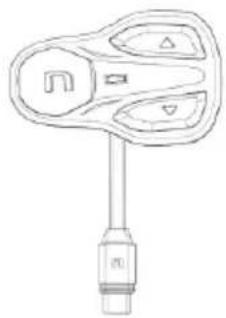
Adesive Keypad

Microphone
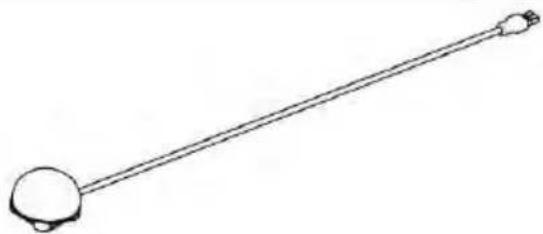
Microphone for helmet X-903

Rechargeable battery

USB-C wire

Adhesive strips for loudspeakers

Flat head tool

Key

Microphone foam
3. INSTALLATION ON THE X-1005, X-903, X-552 HELMET
Important: Prior to installing the N-Com system, it is recommended to write down the identification code affixed to the product (see chapter 19.4).
The installation video can be seen at www.n-com.it / Support section.
3.1. Preliminary operations
- Remove the internal comfort padding by following the specific instructions provided in the helmet user manual, being careful to also remove the size adjustment tab.
- Remove from the polystyrene cheek pads the foam material at the housing of the N-Com earphones. Keep this filling materials should you decide in the future to use the helmet without the N-Com system installed.
3.2. Installing the system in the X-1005, X-903, X-552 helmets
- On the left side of the helmet, open the cheek pad lining door (Fig. 1). Remove the filling material. Keep it in case you want to use your helmet without the N-Com system installed in the future.
- Remove the small N-Com cap positioned on the left side of the helmet. To make the operation easier, we recommend pushing the cap from inside the helmet (Fig. 2).
- Thoroughly clean the outside surface of the shell to make sure that the adhesive keypad sticks properly. Before you apply the keypad, make sure that the shell area is completely clean and grease or dirt free.
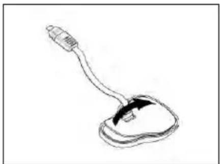
- Remove the protective film from the back of the adhesive keypad using the special tab (Fig. 3).
• Pass the keypad cable through the hole in the outer shell (Fig. 4). - Apply the keypad to the shell and press down on its entire surface to make sure that it sticks properly (Fig. 5).

Fig. 1

Fig. 2
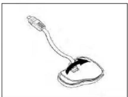
Fig. 3

Fig. 4

Fig. 5
N.B.: Make sure you do not glue the cable underneath the keypad.
N.B.: In the event that the keypad is not positioned correctly, peel it off right away with extreme care and repeat the positioning.
N.B.: It takes up to 24 hours for the keypad to stick completely. During this time, do not expose the helmet to atmospheric agents.
- Position the e-box in its seat (Fig. 6).
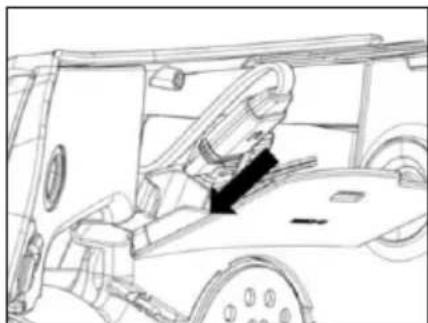
• Line up the keypad connector to the e-box (Fig. 7). - Gently position the connector in its seat until it is all the way in (Fig. 8).

Fig. 6

Fig. 7
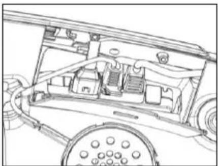
Fig. 8

Fig. 9
- Connect the battery to the cable in the direction indicated by the arrows (Fig. 9).
-
Check that the system is switched on correctly. Press and hold the "n" key for about 2 seconds, until the blue LED light on the keyboard turns on and you hear the voice prompt. Proceed with installation.
-
Position the left loudspeaker in its seat, inserting the cable in the special groove. If necessary, secure the earphone using the adhesive supplied as standard equipment (Fig. 10).
- Hook up the microphone to the connector coming out of the e-Box (Fig. 11).

Fig. 10

Fig. 11
3.3. Microphone positioning
ONLY FOR X-1005 HELMETS
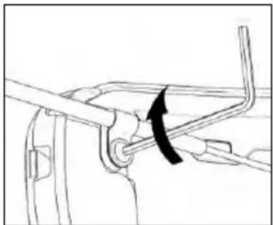
- With the help of the flat head tool supplied as standard equipment, open the microphone-holder clip located on the right side of the helmet (Fig. 12-13).
- Position the microphone at the desired length, sliding the excess portion inside the cheek pad lining (Fig. 14).
N.B.: To ensure good voice transmission quality, it is recommended to adjust the length of the microphone so that the foam part is in front of your mouth. - Close the clip. Make sure that the microphone side with the letter "n" is facing the inside of the helmet (Fig. 15).
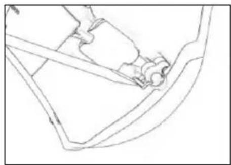
Fig. 12

Fig. 13

Fig. 14

Fig. 15
ONLY FOR X-903, X-552 HELMETS
- Hook up the specific microphone for full-face helmets in its seat in the chin guard (Fig. 16).
- Position the microphone wire in the vertical groove and afterwards behind the cheek pad lining (Fig. 17 – 17B). If necessary, lift up the groove tabs and the cheek pad lining using a flat head tool (supplied as standard equipment).

Fig. 16
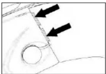
Fig. 17

Fig. 17B
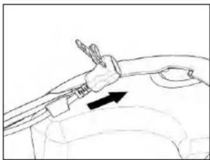
Fig. 18
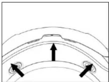
Fig. 19
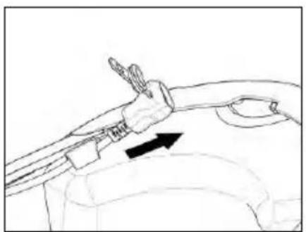
• Pass the charging cable through the elastic band found on the comfort padding (Fig. 18).
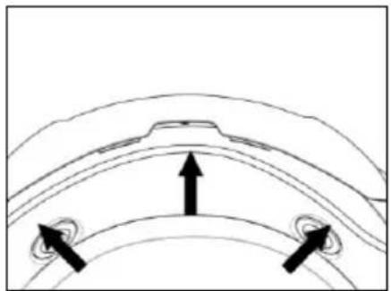
- Position the wiring in the rear part of the helmet (Fig. 19).
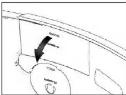
Fig. 20 - X-1005 HELMET

Fig. 21 - X-903 HELMET
- On the right side of the helmet, bend the cheek pad lining and insert the battery in its housing (Fig. 20 - 21 - 22). ONLY FOR X-1005 HELMETS: Remove the filling material. Keep it in case you want to use the helmet without the N-Com system installed in the future.

Fig. 22

Fig. 23
- Position the right loudspeaker in its housing, inserting the cable in the special groove (Fig. 23). If necessary, secure the earphone using the adhesive supplied as standard equipment.
3.4. Repositioning the padding
Reposition the internal comfort padding by following the specific instructions provided in the helmet user manual.
Warning: Always verify the proper length of your chinstrap and adjust it if necessary, referring to the specific helmet instructions.
4. INSTALLATION ON THE X-LITE HELMETS
This procedure must be followed for the installation of N-Com systems on X-lite helmets other than model X-1005, X-903, X-552.
Important: Prior to installing the N-Com system, it is recommended to write down the identification code affixed to the product (see chapter 19.4).
The installation video can be seen at www.n-com.it / Support section.
4.1. Preliminary operations
- Remove the internal comfort padding by following the specific instructions provided in the helmet user manual.
- If present, remove from the polystyrene cheek pads the foam filling material that cover the housings of the N-Com earphones. Keep this filling materials should you decide in the future to use the helmet without the N-Com system installed.
4.2. Installing the system in the helmet
- Remove the small N-Com cap positioned on the left side of the helmet. To make the operation easier, we recommend pushing the cap from inside the helmet (Fig. 24).
- Thoroughly clean the outside surface of the shell to make sure that the adhesive keypad sticks properly. Before you apply the keypad, make sure that the shell area is completely clean and grease or dirt free.
- Remove the protective film from the back of the adhesive keypad using the special tab (Fig. 25).
• Pass the keypad cable through the hole in the outer shell (Fig. 26).

Fig. 24

Fig. 25

Fig. 26
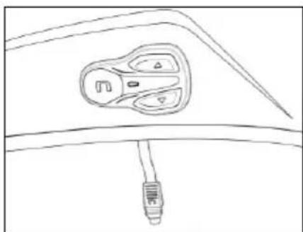
Fig. 27
- Apply the keypad to the shell and press down on its entire surface to make sure that it sticks properly (Fig. 27).
N.B.: Make sure you do not glue the cable underneath the keypad.
N.B.: In the event that the keypad is not positioned correctly, peel it off right away with extreme care and repeat the positioning.
N.B.: It takes up to 24 hours for the keypad to stick completely. During this time, do not expose the helmet to atmospheric agents.
- Position the e-box inside its housing in the left cheek pad (Fig. 28).
• Line up the keypad connector to the e-box (Fig. 29).
• Gently position the connector in its seat until it is all the way in (Fig. 30).

Fig. 28
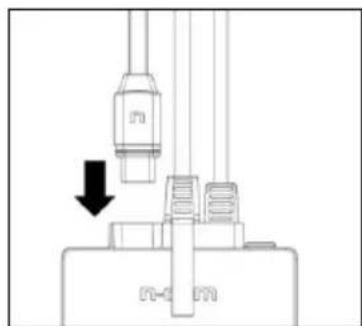
Fig. 29

Fig. 30

Fig. 31
- Connect the battery to the cable in the direction indicated by the arrows (Fig. 31).
- Check that the system is switched on correctly. Press and hold the "n" key for about 2 seconds, until the blue LED light on the keyboard turns on and you hear the voice prompt. Proceed with installation.
• Temporarily reposition the polystyrene cheek pad inside the helmet.
- Position the battery in the right polystyrene cheek pad housing and secure it using the Velcro ribbon (Fig. 32).
- Position the right-hand side speaker in the specific cheek pad housing and secure it using the specific adhesive (Fig. 33).

Fig. 32

Fig. 33
ONLY FOR FULL-FACE HELMETS: Insert the chin strap into the polystyrene cheek pad loop.

Fig. 34
- Arrange the battery connector behind the polystyrene cheek pad.
- Position the wiring in the rear part of the helmet (Fig. 34).
4.3. Microphone positioning
FLIP UP OR JET HELMETS
NB: The parts required for positioning the microphone (microphone clamp and screw) can be found inside the helmet on the left side of the internal shell.
Should the helmet not contain these parts, the microphone clamp and screw are available to buy separately from your Nolangroup dealer.
- Insert the microphone clamp on the arm of the microphone (Fig. 35).
- Position the microphone on the left side of the helmet, screwing in the screw in the small shell frame (Fig. 36). Make sure that the side of the microphone with the caption "n" is facing the inside of the helmet (Fig. 37).
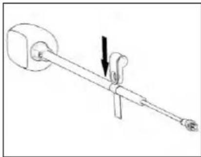
Fig. 35

Fig. 36

Fig. 37
N.B.: On certain helmets, the housing for the microphone rod must be created by cutting out the helmet border gasket along the pre-cut area.
FULL-FACE HELMETS
- Take the polystyrene check pad (left side) and position the microphone in the special housing. Make sure that the side of the microphone with the caption "n" is facing the inside of the helmet.
- Connect the microphone to the connector coming out of the e-box (Fig. 38).
- Position the left-hand side speaker in the cheek pad housing and secure it using the specific adhesive (Fig. 39).
- Reposition the left polystyrene cheek pad in its housing.
ONLY FOR FULL-FACE HELMETS: Insert the chin strap into the polystyrene cheek pad loop.

Fig. 38

Fig. 39
4.4. Repositioning the padding
• Pass the USB-C wire through the elastic band found on the comfort padding.
- Replace the internal comfort padding by following the specific instructions found in the helmet user manual.
Warning: Always verify the proper length of your chinstrap and adjust it if necessary, referring to the specific helmet instructions.
Warning: After the B602 is installed on the helmet, make sure the microphone is properly positioned in front of your mouth, if necessary adjusting the moveable element.
Warning: The wind protector, supplied as standard equipment with helmets that can be opened, may make it more difficult to open and close the chin guard when the microphone is installed.
5. REMOVING THE SYSTEM
To remove the system from the helmet, proceed as for the installation, by removing the various parts.
Important: to remove the keypad, proceed as follows.
- Remove the keypad from the helmet shell (Fig. 40).
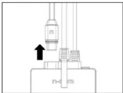
- Unplug the keypad connector (Fig. 41).
- Now completely remove the keypad from the helmet.
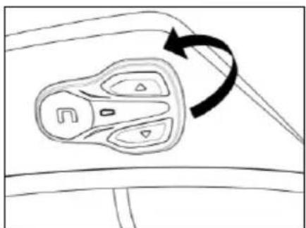
Fig. 40

Fig. 41
The keypad can be removed in case you decide to no longer use the system. However, it cannot be reused again as it will have lost its adhesive properties. Contact your local dealer to purchase a new keypad double sided-adhesive tape that will stick properly to the helmet shell.
6. BASIC FUNCTIONS
Note: Before using the N-Com device for the first time, recharge the battery completely for at least 10 hours. To obtain best performances from the battery, it is recommended to completely recharge the battery the first few times. Afterwards, you can recharge the battery for shorter periods. Whenever possible, it is best to recharge the battery completely.
| System ON | Press and hold the “n” key for about 2 seconds, until the LEDs turn on and you hear the voice prompt. |
| System OFF | Press and hold the “n” key for about 4 seconds, until the LEDs turn off and you hear the voice prompt. |
6.1. Complete Mode and Simple Mode
The B602 system offers two user modes, Complete and Simple. You choose which mode you prefer according to your requirements, thus making the most of your experience on the road.
Available functions depend on which user mode is selected. At the beginning of each section below, you will find confirmation as to whether the function is available only in Complete Mode. If this is not specified, the function on this system can be used in both user modes.
The system is preset with Complete Mode.
It is possible to change to Simple Mode as follows:
Via the N-Com system
- Whilst the system is switched off, press and hold the "n" and "▼" keys simultaneously for 5 seconds.
- You will hear the voice message "Simple user interface enable".
- The system will shut down. When you next turn it on, Simple Mode will have been activated.
To reactivate Complete Mode, follow the above steps. You will hear the voice message "Simple user interface disable".
Via the N-Com EASYSET app
- Access the "Basic Settings" menu and enable the "Simple Mode" option.
Via your computer using the N-Com EASYSET program
- Access the "Settings" menu and select "Simple Mode".
6.2. Volume adjustment
You can easily adjust the volume by tapping the “▲” or the “▼” key. You will hear a beep when the volume reaches the maximum or minimum level.
Some volume parameters can be adjusted through the N-Com EASYSET APP for smartphone or the N-Com EASYSET computer program (chapter 4.5).
N.B.: The volume level set during the trip is not stored when the system is turned off. Each time the N-Com system is switched on, the audio goes back to the set default volume level.
6.3. Auto Off function
The Auto Off function automatically shuts down the N-Com system after five minutes without an active Bluetooth connection (telephone, GPS, motorbike audio system etc) or communication via intercom.
The "Auto Off" function is enabled by default on the device.
You can enable / disable the function from the Configuration Menu (Chapter 6).
6.4. Multi-language voice messages

"Voice prompts" are available only in Complete Mode.
The N-Com system offers voice prompts providing system information and confirmation of which functions are activated or disactivated. The default language is English.
It is possible to change the language as follows:
Via the N-Com system
- Select Configuration Menu: with the N-Com already switched on, press and hold the “▲” and “▼” keys simultaneously, until the red LED light appears.
- Press the "▲" key until you find "Language" mode.
- Press the "n" key to access the list of available languages.
- Press the “▲” and “▼” keys to navigate between the various languages. When you find the language you require, press the “n” key to confirm your choice. A voice prompt in your chosen language will confirm its selection.
Via the smartphone N-Com EASYSET app
- Access the Basic Settings menu and under "Language" select your chosen language from the dropdown menu.
Via your computer using the N-Com EASYSET program
- Connect the N-Com system to the N-Com EASYSET program.
- Select the Settings menu and under the heading "Language", select your chosen language from the drop-down menu.
Available languages: English, Italian, French, German, Spanish, Dutch, Polish, Slovenian.


The default function is enabled on the device.
You can enable / disable the "VOICE PROMPTS" function by using the N-Com EASYSET program or the N-Com EASYSET APP.
6.5. N-Com EASYSET

"N-Com EASYSET" is the application that can be used to manage and configure the B602 system. The program can be downloaded from the Internet site www.n-com.it, in the "Support/Download" section. The functions that can also be managed from the N-Com EASYSET are listed here below with the specific icon.
The N-Com system can be managed from the dedicated App "N-Com EASYSET", which makes it possible to configure the N-Com system directly from your Smartphone. The N-Com APP can be downloaded free of charge from Google Play or Apple Store. For additional details, please visit the website www.n-com.it The functions that can also be managed from the N-Com EASYSET App are listed here below with the specific icon.
6.6. Updating the firmware
Firmware updates for the N-Com system can be installed using the N-Com EASYSET program on your computer, or the N-Com EASYSET app on your smartphone.
Via your computer with the N-Com EASYSET program
- Download the N-Com EASYSET program from the N-Com website – in the "Support"/"Download"/"Software" section.
- Hook up the N-Com system to the computer and open the N-Com EASYSET program.
- Follow the directions until the program recognises the N-Com system.
- From the screen "FIRMWARE UPDATE", select the desired language from the drop-down menu.
- Click on "DOWNLOAD" and save the file in the computer.
- Click on "UPDATE" and wait for the firmware update to end.
Via the N-Com EASYSET app for smartphones
- Download and install the N-Com EASYSET app from Google Play or Apple Store.
- Pair and connect the telephone to the N-Com system (section 7).
- On opening, the app recognizes the firmware version installed on the N-Com system. If an update is available, follow the directions provided by the app.
The release notes of the last Firmware version can be found on the website www.n-com.it – in the "Support"/"Download"/"Software" section.
7. PAIRING MODE
All the Bluetooth pairing operations are carried out in this mode.
In order to access the Pairing function, starting with the N-Com system switched off, press and hold the "n" key for 4 seconds, until the red LED light appears.
7.1. Pairing Menu

The "Pairing Menu" is available only in Complete Mode.
Once in the "Pairing" menu, press the "▲" and "▼" keys to scroll through the various menu items.
The following items make up the "Pairing" menu:
A. Mobile phone pairing (chapter 7)
B. Intercom pairing (chapter 12)
C. Pairing with Other N-Com Systems (chapter 12.2)
D. Universal Intercom pairing (chapter 13)
E. Second mobile phone pairing (chapter 8)
F. GPS pairing (chapter 11)
G. Remote control pairing (chapter 14)
H. Delete all pairings
In order to delete all Bluetooth pairings stored in the device, press the "▲" or "▼" key until you hear the voice prompt "Delete all pairings".
Press the "n" confirmation key to delete all Bluetooth devices stored in memory.
I. Exiting the configuration
To exit the "Pairing" menu, press the "▲" or "▼" key until you hear the voice prompt "Exit configuration". Press the "n" confirmation key to exit the "Pairing" menu.
If no key is pressed within 15 seconds, the device automatically exits the "Pairing" menu.
The "Configuration Menu" is available only in Complete Mode.
All the settings of the N-Com system are managed in this mode.
To access the Configuration Menu starting with the N-Com switched on, press and hold the “▲” and “▼” keys simultaneously for 4 seconds, until the red LED light appears.
Once in the "Configuration" menu, press the "▲" and "▼" keys to scroll through the various menu items.
In the items marked with an “*”, it is possible to enable / disable the function by pressing the "n" key to confirm.
The following items make up the "Configuration" menu:
A. Speed dial* (chapter 9.1)
B. Smart Navi System* (chapter 9.3)
C. Auto Off*(chapter 4.3)
D. Audio boost*
By enabling the "Audio boost", all the audio sources inside the device will be reproduced at a higher and potentially less clear volume.
Press the "n" confirmation key to enable / disable the function, which is not enabled by default on the device.
E. Language
To change the language in which the system provides voice prompts, please see section 4 of the Manual.
F. Reset
In order to restore the factory settings of the device, press the “▲” or “▼” key until you hear the voice message "Factory Reset". Press the "n" confirmation key to restore all the factory settings of the device. The system will shut down automatically.
G. Exiting the configuration
To exit the "Configuration" menu, press the "▲" or "▼" key until you hear the voice prompt "Exit configuration".
Press the "n" confirmation key to exit the "Configuration" menu.
If no key is pressed within 15 seconds, the device automatically exits the "Configuration" menu.
9. MOBILE PHONE / MP3 PLAYER PAIRING
• Make sure the B602 is turned off.
- Put the system in "Pairing" mode: press and hold the "n" key for 4 seconds, until the red LED light appears.
- In Complete Mode. press the "▲" key until "Phone pairing" appears. In Simple Mode do not press any key.
- Activate the search of Bluetooth devices on the mobile phone.
- Select the N-Com device. If a password is requested, enter 0000 (four zeros).
- Connection between the two devices is established after a few seconds.
N.B.: The affiliation is stored in the helmet and in the cell phone and it is not lost when the two devices are turned off. As a result it needs to be carried out only once.
NB: if a Bluetooth device has already been stored in the B602 system's memory, any new pairing will overwrite the previous pairing.
| Automatic Connection | Once the Bluetooth device has been paired, connection is automatic when the system is turned on. |
| Manual Connection | In case connection is not automatically initiated after a few seconds, you can connect from the Bluetooth device or by pressing and holding the “n” key for about 2 seconds. |

10. SECOND MOBILE PHONE PAIRING
The "Second mobile phone" function is available only in Complete Mode.
The B602 system can be hooked up to two phones at the same time. The second phone (secondary device) can receive calls but not make them.
To pair the second Bluetooth phone (secondary device):
• Make sure the B602 is turned off.
- Put the system in "Pairing" mode: press and hold the "n" key for 4 seconds, until the red LED light appears.
- Press the "▲"key until you hear the voice prompt "Second mobile phone pairing".
- Activate the search of Bluetooth devices on the mobile phone.
- Select the N-Com system from the list. If a password is requested, enter the code 0000 (four zeros).
• After a few seconds, the connection between the two devices is activated.
Once the Bluetooth device has been paired, connection is automatic when the system is turned on.
N.B.: The affiliation is stored in the helmet and in the cell phone and it is not lost when the two devices are turned off. As a result it needs to be carried out only once.
NB: if a second device has already been stored in the B602 system's memory, any new pairing will overwrite the previously stored pairing.
11. MOBILE PHONE
To pair a mobile phone to the B602 system, follow the procedure illustrated in Chapter 7.
| Answering a phone call | Briefly press any key when you hear the incoming call signal. |
Vocal answer (VOX phone)The “ VOX phone ” function is available only in Complete Mode. function is available only in Complete Mode. | When you hear the ringtone, say any word out loud.You can enable / disable the “VOX phone” function by using the N-Com EASYSET program or the N-Com EASYSET APP.The function is not active during the intercom connection. |
| Voice assistant | Press and hold “n” key for about 2 seconds. |
| Hanging up/rejecting a phone call | Press and hold “n” key for about 2 seconds. |
| Manual phone connection | Press and hold “n” key for about 2 seconds. |
11.1. Speed dial
The "Speed Dial" function is available only in Complete Mode.

Using the N-Com EASYSET program or the N-Com EASYSET App, you can store up to 3 of your favourite numbers, which you will be able to dial from the "Speed Dial" menu.
Saving the Speed Dial numbers
To assign one or more speed dialling numbers:
- Select Configuration Menu: with the N-Com system already switched on, press the “▲” e “▼” keys simultaneously for 4 seconds, until the red LED light appears.
- Press the "▲" or "▼" key until you hear the voice prompt "Speed dial".
- Press the "n" confirmation key. You will hear the voice prompts "Speed dial 1" and "Phone connected".
- Press the "▲" or "▼" keys to select the speed dialling number to be assigned. The saved position is confirmed by the voice prompt "Speed dial 1" / "Speed dial 2" / "Speed dial 3".
- On your own mobile phone (paired and connected to the N-Com system), call the phone number you wish to assign to the selected speed dialling position. The call is interrupted before it goes through, and the selected number will be saved; at this point you will hear the special voice prompt confirming the selection ("Save Speed Dial 1" / "Save Speed Dial 2" / "Save Speed Dial 3").
Using the stored numbers
To access the "Speed Dial" menu, press simultaneously the "n" and "▼" keys ("Speed Dial"), then use the "▲" and "▼" keys to scroll through the menu items.
Then press the "n" key to confirm the selection of one of the following items:
• Last number redial
- Speed Dial 1
- Speed Dial 2
- Speed Dial 3
- Cancelled
If you wish to exit the "Speed Dial" menu, press and hold the "▲" and "▼" keys until you hear the command "Cancelled", then press "n" to confirm.
N.B.: If no key is pressed within 15 seconds, the system exits the "Speed Dial" menu.
11.2. Conference call function

The "Conference call" function is available only in Complete Mode.
When a call comes in on a mobile phone connected via Bluetooth to B602, the intercom is temporarily turned off. However, if you wish to share the phone call with the other helmet, simply turn on the intercom manually during the phone call.
| Turning on the phone conference call function | During the phone call, briefly press “n”. |
| Turning off the phone conference call function | During the phone call, briefly press “n”. |
N.B.: "Telephone Conference" function can only be used between the N-Com series "600"/"800"/"900".
11.3. Smart Navi System

The "Smart Navi System" function is available only in Complete Mode.
The "SMART NAVI SYSTEM" function allows you to listen to navigator directions coming from the smartphone even during an intercom call.
The audio stops to allow transmission of the navigator directions from the smartphone and is automatically re-established at the end of said instructions.
The "SMART NAVI SYSTEM" function is disabled by default on the device.
You can enable / disable the function from the Configuration Menu (Chapter 6).
N.B.: With the Smart Navi System enabled, all audio information coming from the smartphone (for example, notification sounds) temporarily stops the audio under way.

You can enable / disable the "SMART NAVI SYSTEM" function by using the N-Com EASYSET program or the N-Com EASYSET APP.
To pair a mobile phone or an Mp3 device to the B602 system, follow the procedure illustrated in Chapter 7.
| Play music (Play) | Press and hold the “▲” key for about 2 seconds. | |
| Pause function (Pause) | When the player is connected and playing music, press and hold the “▲” key for about 2 seconds. | |
 | Next track (Skip)The “Skip” function is available only in Complete Mode. | When the player is connected and playing music, press and hold the “▲” key for about 3 seconds. |
 | Previous track (Rew)The “Rew” function is available only in Complete Mode. | When the player is connected and playing music, press and hold the “▼” key for about 3 seconds. |
12.1. Sharing music via Bluetooth (A2DP Sharing)

The "Music Sharing" function is available only in Complete Mode.
During the intercom connection, you can start playing music by pressing the “▲” key for about 2 seconds. The music will be played in both systems.
Music sharing temporarily cuts off the intercom conversation; however, this can be automatically restored by stopping the music (pressing the “▲” key for about 2 seconds).
N.B.: Music shared through the intercom can be managed by both systems, for example, both systems can change the track by pressing the relevant command.
N.B.: the "Music Sharing" function can only be used between the N-Com series "600"/"800"/"900".
13. GPS PAIRING
B602 system is compatible with the most common satellite navigators for motorcycles. For a list of compatible models and additional details, visit the website www.n-com.it
• Make sure the B602 is turned off.
- Put the system in "Pairing" mode: press and hold the "n" key for 4 seconds, until the red LED light appears.
- In Complete Mode. press the "▲" key until you hear the voice prompt "GPS pairing". In Simple Mode do not press any key.
- Activate the search of Bluetooth devices on the navigator.
- Select the N-Com system from the list. If a password is requested, enter the code 0000 (four zeros).
• After a few seconds, the connection between the two devices is activated.
N.B.: The pairing is stored by both the helmet and the navigator hence it is not lost when they are switched off. This means that this procedure needs to be carried out only once. Once the Bluetooth device has been paired, connection is automatic when the system is turned on.
NB: if the B602 system's memory has already stored a navigator, the new pairing will overwrite the previously paired navigator.
N.B.: Intercom connection is automatically cut off every time the navigator gives directions and restored at the end of the message from the navigator.
14. INTERCOM RIDER-PASSENGER
The N-Com B602 system allows intercom connection via Bluetooth with another N-Com system. In order for the two N-Com systems to communicate, they must first be paired.
14.1. N-Com "600"/"800"/"900" Series Intercom pairing
Important: The procedure described below refers exclusively to pairing with "600"/"800"/"900" series N-Com systems.
- Make sure the systems are turned off.
- Put the systems in "Pairing" mode: press and hold the "n" key for 4 seconds, until the red LED light appears.
- On both the B602 in Complete Mode and the "900"/"800" systems, press the "▲" key until you hear the voice prompt "Intercom Pairing".
With B602 systems in Simple Mode briefly press the "▲" key.
- On one of the two systems, briefly press the "n" key.
- After a few seconds the systems recognize each other and intercom communication is established.

Through the N-Com EASYSET APP, the "Intercom Easy Pairing" can be carried out. This mode allows the N-Com systems to be recognised and stored through a QR code generated on your smartphone.
The Intercom Easy Pairing function is only available for the N-Com series "600"/"800"/"900".
14.2. Pairing with other N-Com Systems

The "Pairing Other N-Com" function is available only in Complete Mode.
Important: The procedure described here below refers exclusively to pairing "600" series N-Com systems with N-Com systems OTHER THAN the "600"/"800"/"900" series 1 .
- Make sure the systems are turned off.
- Put the B602 system in "Pairing" mode: press and hold the "n" key for 4 seconds, until the red LED light appears.
- Set the N-Com system (excluding the "600"/"800"/"900" series) to "Pairing": press and hold the "n" key for 4 seconds, until the LED light flashes rapidly.
- On the B602 system, hold the "▲" key until you hear the voice prompt "Pairing other N-Com" and then briefly press the "n" key.
- After a few seconds the systems recognize each other and intercom communication is established.
14.3. Intercom function
To activate the intercom connection, turn on the two N-Com systems and briefly press the "n" key on one of the two systems.
| Intercom connection | Briefly press “n”. |
| Disconnection of active intercom | Briefly press “n”. |

N.B.: In case the pre-setting position is empty, or the system being called cannot be reached within the maximum range or it is already engaged in a phone call, you will hear an error voice message.
15. "UNIVERSAL INTERCOM" INTERCOM

The "Universal Intercom" function is available only in Complete Mode.
The N-Com B602 system can be connected via Bluetooth to intercom systems of other brands, thanks to the UNIVERSAL INTERCOM function 2 .
15.1. Pairing with the UNIVERSAL INTERCOM
The N-Com system can be paired with the other intercom (from now on referred to as Intercom B) as if it was a mobile phone.
• Make sure the B602 is turned off.
- Put the B602 system in "Pairing" mode: press and hold the "n" key for 4 seconds, until the red LED light appears.
- Press the "▲" key until you hear the voice prompt "Universal intercom pairing".
- Put intercom B in the mobile phone pairing mode. Important: If the intercom allows management of two mobile phones, put it in pairing mode of the second mobile phone. By doing so, it will be possible to maintain the connection to your own mobile phone even during intercom communication (refer to the Intercom B manual).
- On the B602 system, briefly press the "n" key.
- After a few seconds the systems recognize each other and intercom communication is established.
15.2. Universal Intercom Function
To turn on and off the audio between two helmets, proceed as follows:
From the N-Com B602 system:
Connect or disconnect Intercom B as you would for a regular N-Com intercom (chapter 15). Intercom B may receive a dialling tone that must be answered with a phone reply command.
From intercom B
To enable the intercom connection, press the "Voice Call" or "Last number redial" command.
To disable the intercom connection, press the "Hang up" or "Reject phone call" command.
N.B.: Some systems are not able to handle the activation / deactivation of the intercom connection. In this case, operate from the B602 system.
N.B.:
- During use of the UNIVERSAL INTERCOM, the B602 system keeps the connection active to the MAIN DEVICE only (and not to the SECOND MOBILE PHONE or to the SATELLITE NAVIGATOR).
- The intercom system connected to N-Com B602 may not allow simultaneous connection to a mobile phone.
- Only one system paired in Universal Intercom mode can be stored.
16. REMOTE CONTROL

The "Remote Control" function is available only in Complete Mode.
The B602 device can be controlled by using a remote control (sold separately), so that you do not have to take your hands off the handlebars to use the keypad.
The N-Com system is compatible with the RC4 Remote Control by SENA.
The following table shows the correspondence of the keys:
| N-COM SYSTEM | ▲ | ▼ | n | / |
| SENA RC4 | + | - | CENTRAL KEY | MULTI-FUNCTION KEY |
Proceed as follows to pair the N-Com system to the RC4 Remote Control:
- Make sure the RC4 is switched off.
- Put the RC4 in pairing mode: press and hold the "+" key for about 8 seconds.
- Make sure the B602 is switched off.
- Put the B602 system in "Pairing" mode: press and hold the "n" key for 4 seconds, until the red LED light appears.
- Press the "▲" key until you hear the voice prompt "Remote control pairing".
- Press the "n" key on the N-Com system keypad.
- After a few seconds, the connection between the two devices is confirmed by the voice prompt "Remote control connected".
N.B.: The affiliation is saved by both the helmet and the remote control and it is not lost when the two systems are turned off. Hence this procedure must only be carried out once.
17. BATTERY AND RECHARGE
17.1. Low battery signal
During its operation, the system alerts the user with a voice message when the battery is low. From the first message, the system has a 1-hour autonomy. Warning is given every 10 minute.
17.2. Checking the Battery Level
LED Indicator
When the system is powering on, their blue LED flashes rapidly indicating the battery level.
4 flashes = High, 70 \~ 100%
3 flashes = Medium, 30 \~ 70%
2 flashes = Low, 0 \~ 30%
Vocal Indicator
Starting from the system turned off, press at the same time the "n" and "▲" keys for about 3 seconds until you hear three, high toned beeps. Then you will hear a voice prompt indicating the battery level.
However, if you release the keys as soon as the system turns on, you will not hear a voice prompt for the battery level indication.
17.3. Charging the system

Fig. 42
- To charge the system, connect the system to a charger or USB plug using the USB-C cable supplied.
The charge will take place as follows:
| B602 system turned off | When the B602 system is connected to the battery charger, the blue LED starts to flash quickly. When the battery is charged, the blue LED becomes steady. |
| B602 system turned on | When the B602 system is connected to the battery charger, the blue LED starts to flash quickly. When the battery is charged, the blue LED goes back to its standard flashing. |
Note: In case you don't plan to use the N-Com system for a long time, you need to fully recharge the device before storing it away.
Note: In case the device is not used for a long time, carry out a complete recharging cycle of the device at least once every 6 months to avoid possible damage to the battery.
Note: In case the N-Com system is left for more than 6 months without ever being recharged, the device may not switch on; in this case, recharge the N-Com system for at least 24 hours (even if the blue signalling LED is not flashing), then try to switch on the device again.
18. SUMMARY TABLE OF CONTROLS
Complete Mode
| Key | n | ▲ | ▼ | ▲+▼ | |
| Basic Functions | Turn On | 2 sec | |||
| Turn Off | 4 sec | ||||
| Increase Volume | X | ||||
| Reduce Volume | X | ||||
| Pairing Menu (with system switched off) | 4 sec | ||||
| Configuration Menu (with system switched on) | 4 sec | ||||
| Complete/Simple Mode** (with system switched off) | 5 sec | 5 sec | |||
| Reset** (with system switched on) | 5 sec | 5 sec | |||
| Bluetooth Devices | Answering telephone calls* | X | X | X | |
| Voice calls | 2 sec | ||||
| Speed Dial Menu** | X | X | |||
| Finishing/Refusing Calls | 2 sec | ||||
| Manual Connection to Device | 2 sec | ||||
| Activating Conference Calls | X | ||||
| Disactivating Conference Calls | X | ||||
| Bluetooth Music | Play music | 2 sec | |||
| Pause music | 2 sec | ||||
| Next track (Skip) | 3 sec | ||||
| Previous track (REW) | 3 sec | ||||
| Music sharing A2DP | 2 sec | ||||
| N-Com Intercom (serie 900-600) | Intercom connection | X | |||
| Disconnecting active intercom | X | ||||
*Press any key on the N-Com keypad.
**Press the keys simultaneously.
Simple Mode
| Key | n | ▲ | ▼ | ▲+▼ | |
| Basic Functions | Turn On | 2 sec | |||
| Turn Off | 4 sec | ||||
| Increase Volume | X | ||||
| Decrease Volume | X | ||||
| Pairing Menu (with system switched off) | 4 sec | ||||
| Complete/Simple Mode ** (with system switched off) | 5 sec | 5 sec | |||
| Reset** (with system switched on) | 5 sec | 5 sec | |||
| Cancel pairing** (via the Pairing function) | 4 sec | 4 sec | |||
| Bluetooth Devices | Answering telephone calls* | X | X | X | |
| Finishing/Refusing Calls | 2 sec | ||||
| Manual Connection to Device | 2 sec | ||||
| N-Com Intercom (900-600 series) | Intercom Connection | X | |||
| Disconnecting Active Intercom | X | ||||
*Press any key on the N-Com keypad.
**Press the keys simultaneously.
19. WARRANTY
With this WARRANTY CERTIFICATE, Nolangroup warrants to the purchaser that the product, at the time of purchase, is free from defects in materials and workmanship.
We kindly ask you to:
- Read the warnings for safety and proper use.
- Read the warranty terms and conditions.
- Keep the original purchase receipt. This receipt must be presented in case of repairs under warranty. In these cases, the product must be sent to the dealer where the purchase was made.
19.1. Warranty coverage and validity
If any defect covered by this Warranty Certificate is detected within the period listed on the website (Support/Instructions Manuals) and based on the country in which the product has been purchased (proof will be the purchase date on the receipt), Nolangroup will repair or replace the defective product through its distribution network and after having verified the defect. Nolangroup will provide all material and labour reasonably necessary to remedy the claimed defect, except in the cases where damage is caused by one of the items listed in the following paragraph "Exclusions and limitations of coverage".
19.2. Exclusions and limitations of coverage
This warranty covers only defects in materials and workmanship.
Nolangroup cannot be held liable for product defects attributable in whole or in part to any other cause, including but not limited to:
- Defects or damage resulting from use of the Product in conditions other than the usual ones.
- Damage caused by improper use and not in compliance with normal operation as indicated in the instructions for use and maintenance of the product provided by Nolangroup.
- Neglect and normal wear and tear of internal and external parts.
- Any damage resulting from an accident.
- Any modification or tampering made to the helmet or to the N-Com system by the user or third parties.
- Use of incompatible accessories not approved by Nolangroup for the purchased N-Com device model.
- Consumable parts considered to be subject to wear and tear, such as the rechargeable battery and the connection cables between N-Com systems and other devices.
- The proper functioning of the product/peripheral device combination when the product is used together with accessories or equipment for which Nolangroup has not verified compatibility.
- All specific and subjective situations that may arise during actual use of the helmet, such as, for example, problems related to comfort while riding or aerodynamic noise.
Under no circumstances shall Nolangroup be liable for any incidental or consequential damages (including, without any limitation whatsoever, injuries to one or more persons) resulting from failure to fulfil the obligations arising from this warranty regarding Nolangroup products.
19.3. Procedure for submitting claims
In order to submit any claim covered by this warranty, the purchaser must notify directly the dealer where the N-Com system was purchased of the alleged defect, presenting at the same time the product which is the object of the claim and a copy of the sales receipt.
PRIOR TO CONTACTING THE DEALER, WE RECOMMEND THAT YOU CAREFULLY READ THE INSTRUCTIONS FOR USE ENCLOSED WITH THE PRODUCT.
THE WARRANTY IS EFFECTIVE EXCLUSIVELY FROM THE DATE OF PURCHASE UNTIL THE PERIOD INDICATED FOR THE COUNTRY WHERE THE PRODUCT WAS PURCHASED - see list available on the website (Support/ Instructions manuals).
Any repairs or other jobs carried out under warranty do not extend the period of the warranty itself.
Hence, in case the product or one of its components is replaced, this does not mean the start of a new warranty period, as the purchase date of the original product will be taken into account for warranty purposes.
Only for repairs or replacements of electronic components, if Nolangroup repairs or replaces the product, the product will have a warranty period equal to the remaining part of the original warranty or ninety (90) days from the date of repair (whichever is longer).
Repair or replacement may also be carried out using regenerated components with equivalent functions. Replaced parts or components will become the property of Nolangroup.
NOLANGROUP RESERVES THE RIGHT TO CHANGE CHARACTERISTICS, FUNCTIONALITY, COMPATIBILITY AND SOFTWARE AT ANY TIME, WITH NO NEED FOR ADVANCE NOTICE.
This warranty does not affect the customer's legal rights under applicable national jurisdiction and the consumer's rights vis-à-vis the dealer under the purchase/sale agreement.
19.4. Product identification
N-Com products are identified by means of a code that allows their traceability and identification. The identification code (S/N) can be found on the adhesive label.
FOR USA AND CANADA MARKET ONLY: SPECIAL WARNING
This device complies with Part 15 of the FCC Rules. Operation is subject to the following two conditions: (1) this device may not cause harmful interference, and (2) this device must accept any interference received, including interference that may cause undesired operation of the device.
Changes or modifications not expressly approved by the party responsible for compliance could void the user's authority to operate the equipment.
NOTE: The manufacturer is not responsible for any radio or TV interference caused by unauthorized modifications to this equipment. Such modifications could void the user's authority to operate the equipment.
This equipment has been tested and found to comply with the limits for a Class B digital device, pursuant to part 15 of the FCC rules. These limits are designed to provide reasonable protection against harmful interference in a residential installation. This equipment generates, uses and can radiate radio frequency energy and, if not installed and used in accordance with the instructions, may cause harmful interference to radio communications. However, there is no guarantee that interference will not occur in a particular installation.
This model meets the government's requirements for exposure to radio waves. Your wireless device is a radio transmitter and receiver. It is designed and manufactured not to exceed limits for exposure to radio frequency (RF) energy set by the Federal Communications Commission (FCC) of the U.S. Government and by the Canadian regulatory authorities.
The exposure standard for wireless mobile devices employs a unit of measurement known as the Specific Absorption Rate, or SAR. The SAR limit set by the FCC and by the Canadian regulatory authorities is 1.6 W/kg.1.
For Canada market only:
This EUT is compliant with SAR for general population/uncontrolled exposure limits in IC RSS-247. The N-Com electronic device is positioned on a minimum distance of - see the table below - from the head of the user, therefore no SAR test have been conducted on the product.
| N-COM SYSTEM | DISTANCE FROM THE HEAD |
| B902L R/B902 R | 30.00 mm |
| B602 R | 30.63 mm |
| B101 R | 30.63 mm |
| B902 X | 32.50 mm |
| B602 X | 34.50 mm |
POUR LE MARCHE US ET CANADIEN UNIQUEMENT: MISE EN GARDE SPECIALE
Fig. 1

Fig. 2
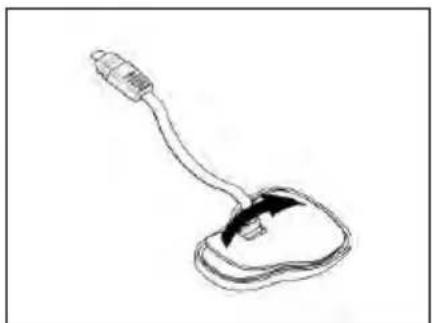
Fig. 3

Fig. 4

Fig. 5
Fig. 6

Fig. 7

Fig. 8
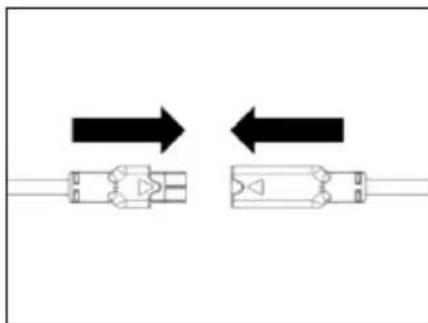
Fig. 9
Fig. 10

Fig. 11
Fig. 12

Fig. 13

Fig. 14

Fig. 15
UNIQUEMENT POUR CASQUE X-903, X-552
Fig. 16
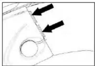
Fig. 17
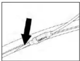
Fig. 17B

Fig. 18
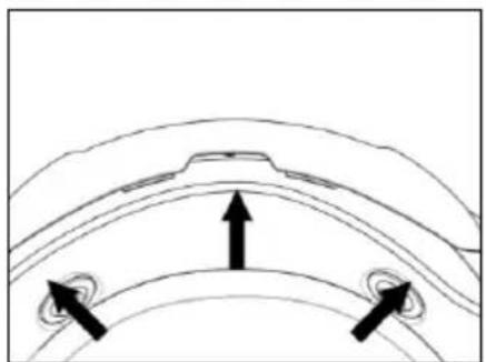
Fig. 19
Fig. 20 - CASQUE X-1005
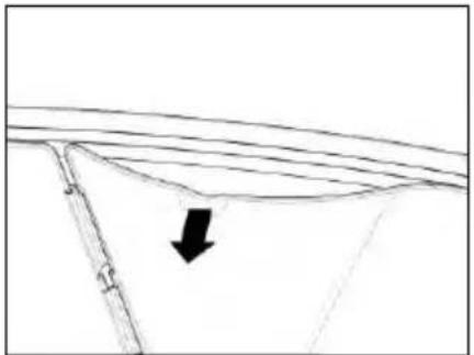
Fig. 22

Fig. 23
Fig. 24

Fig. 25

Fig. 26

Fig. 27
Fig. 28

Fig. 29

Fig. 30

Fig. 31
Fig. 32

Fig. 33
Fig. 34
Fig. 35
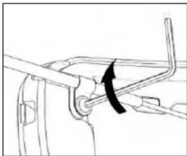
Fig. 36
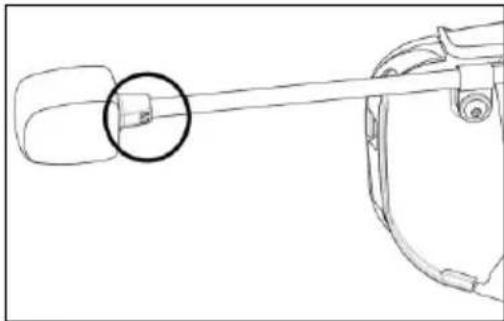
Fig. 37
Fig. 38

Fig. 39
Fig. 40

Fig. 41
Instructions vocales
This device complies with Part 15 of the FCC Rules. Operation is subject to the following two conditions: (1) this device may not cause harmful interference, and (2) this device must accept any interference received, including interference that may cause undesired operation of the device.
Changes or modifications not expressly approved by the party responsible for compliance could void the user's authority to operate the equipment.
NOTE: The manufacturer is not responsible for any radio or TV interference caused by unauthorized modifications to this equipment. Such modifications could void the user's authority to operate the equipment.
This equipment has been tested and found to comply with the limits for a Class B digital device, pursuant to part 15 of the FCC rules. These limits are designed to provide reasonable protection against harmful interference in a residential installation. This equipment generates, uses and can radiate radio frequency energy and, if not installed and used in accordance with the instructions, may cause harmful interference to radio communications. However, there is no guarantee that interference will not occur in a particular installation.
This model meets the government's requirements for exposure to radio waves. Your wireless device is a radio transmitter and receiver. It is designed and manufactured not to exceed limits for exposure to radio frequency (RF) energy set by the Federal Communications Commission (FCC) of the U.S. Government and by the Canadian regulatory authorities.
The exposure standard for wireless mobile devices employs a unit of measurement known as the Specific Absorption Rate, or SAR. The SAR limit set by the FCC and by the Canadian regulatory authorities is 1.6 W/kg.1.
For Canada market only:
This EUT is compliant with SAR for general population/uncontrolled exposure limits in IC RSS-247. The N-Com electronic device is positioned on a minimum distance of - see the table below - from the head of the user, therefore no SAR test have been conducted on the product.
| N-COM SYSTEM | DISTANCE FROM THE HEAD |
| B902L R/B902 R | 30.00 mm |
| B602 R | 30.63 mm |
| B101 R | 30.63 mm |
| B902 X | 32.50 mm |
| B602 X | 34.50 mm |
POUR LE MARCHE US ET CANADIEN UNIQUEMENT: MISE EN GARDE SPECIALE
Abb. 1

Abb. 2

Abb. 3

Abb. 4

Abb. 5
Abb. 6

Abb. 7

Abb. 8

Abb. 9
Abb. 10

Abb. 11
Abb. 12

Abb. 13

Abb. 14

Abb. 15
NUR FÜR DEN X-903, X-552 -HELM
Abb. 16
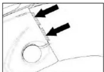
Abb. 17

Abb. 17B

Abb. 18

Abb. 19
Abb. 20 - X-1005 Helm

Abb. 21 - X-903 Helm
Abb. 22

Abb. 23
Abb. 24

Abb. 25

Abb. 26

Abb. 27
Abb. 28
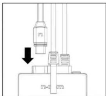
Abb. 29

Abb. 30

Abb. 31
Abb. 32

Abb. 33
Abb. 34
Abb. 35

Abb. 36
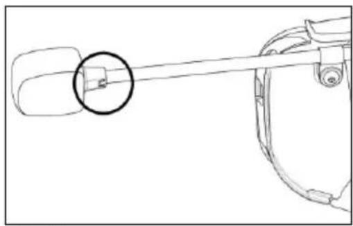
Abb. 37
Abb. 38
Abb. 39
Abb. 40

Abb. 41
This device complies with Part 15 of the FCC Rules. Operation is subject to the following two conditions: (1) this device may not cause harmful interference, and (2) this device must accept any interference received, including interference that may cause undesired operation of the device.
Changes or modifications not expressly approved by the party responsible for compliance could void the user's authority to operate the equipment.
NOTE: The manufacturer is not responsible for any radio or TV interference caused by unauthorized modifications to this equipment. Such modifications could void the user's authority to operate the equipment.
This equipment has been tested and found to comply with the limits for a Class B digital device, pursuant to part 15 of the FCC rules. These limits are designed to provide reasonable protection against harmful interference in a residential installation. This equipment generates, uses and can radiate radio frequency energy and, if not installed and used in accordance with the instructions, may cause harmful interference to radio communications. However, there is no guarantee that interference will not occur in a particular installation.
This model meets the government's requirements for exposure to radio waves. Your wireless device is a radio transmitter and receiver. It is designed and manufactured not to exceed limits for exposure to radio frequency (RF) energy set by the Federal Communications Commission (FCC) of the U.S. Government and by the Canadian regulatory authorities.
The exposure standard for wireless mobile devices employs a unit of measurement known as the Specific Absorption Rate, or SAR. The SAR limit set by the FCC and by the Canadian regulatory authorities is 1.6 W/kg.1.
For Canada market only:
This EUT is compliant with SAR for general population/uncontrolled exposure limits in IC RSS-247. The N-Com electronic device is positioned on a minimum distance of - see the table below - from the head of the user, therefore no SAR test have been conducted on the product.
| N-COM SYSTEM | DISTANCE FROM THE HEAD |
| B902L R/B902 R | 30.00 mm |
| B602 R | 30.63 mm |
| B101 R | 30.63 mm |
| B902 X | 32.50 mm |
| B602 X | 34.50 mm |
POUR LE MARCHE US ET CANADIEN UNIQUEMENT: MISE EN GARDE SPECIALE
Fig. 1
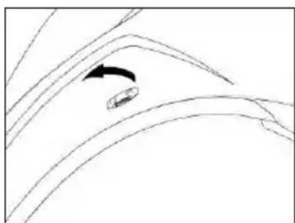
Fig. 2
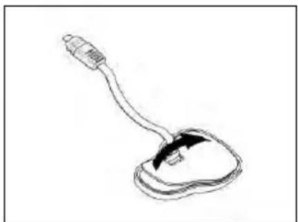
Fig. 3
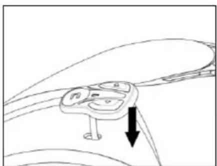
Fig. 4

Fig. 5
Fig. 6

Fig. 7

Fig. 8

Fig. 9
Fig. 10

Fig. 11
Fig. 12

Fig. 13

Fig. 14

Fig. 15
SOLO PARA CASCO X-903, X-552
Fig. 16

Fig. 17
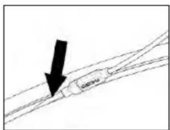
Fig. 17B

Fig. 18

Fig. 19
Fig. 20 - CASCO X-1005

Fig. 21 - CASCO X-903
Fig. 22

Fig. 23
Fig. 24

Fig. 25
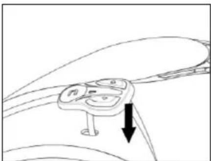
Fig. 26

Fig. 27
Fig. 28
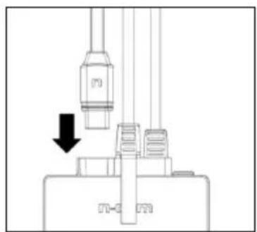
Fig. 29
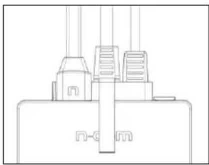
Fig. 30

Fig. 31
Fig. 32

Fig. 33
Fig. 34
Fig. 35

Fig. 36
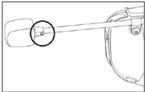
Fig. 37
Fig. 38

Fig. 39
Fig. 40

Fig. 41
This device complies with Part 15 of the FCC Rules. Operation is subject to the following two conditions: (1) this device may not cause harmful interference, and (2) this device must accept any interference received, including interference that may cause undesired operation of the device.
Changes or modifications not expressly approved by the party responsible for compliance could void the user's authority to operate the equipment.
NOTE: The manufacturer is not responsible for any radio or TV interference caused by unauthorized modifications to this equipment. Such modifications could void the user's authority to operate the equipment.
This equipment has been tested and found to comply with the limits for a Class B digital device, pursuant to part 15 of the FCC rules. These limits are designed to provide reasonable protection against harmful interference in a residential installation. This equipment generates, uses and can radiate radio frequency energy and, if not installed and used in accordance with the instructions, may cause harmful interference to radio communications. However, there is no guarantee that interference will not occur in a particular installation.
This model meets the government's requirements for exposure to radio waves. Your wireless device is a radio transmitter and receiver. It is designed and manufactured not to exceed limits for exposure to radio frequency (RF) energy set by the Federal Communications Commission (FCC) of the U.S. Government and by the Canadian regulatory authorities.
The exposure standard for wireless mobile devices employs a unit of measurement known as the Specific Absorption Rate, or SAR. The SAR limit set by the FCC and by the Canadian regulatory authorities is 1.6 W/kg.1.
For Canada market only:
This EUT is compliant with SAR for general population/uncontrolled exposure limits in IC RSS-247. The N-Com electronic device is positioned on a minimum distance of - see the table below - from the head of the user, therefore no SAR test have been conducted on the product.
| N-COM SYSTEM | DISTANCE FROM THE HEAD |
| B902L R/B902 R | 30.00 mm |
| B602 R | 30.63 mm |
| B101 R | 30.63 mm |
| B902 X | 32.50 mm |
| B602 X | 34.50 mm |
POUR LE MARCHE US ET CANADIEN UNIQUEMENT: MISE EN GARDE SPECIALE
2. INNHOLDET I ESKEN....7
3. INSTALLERING INN I HJELM X-1005, X-903, X-552....8
2. INNHOLDET I ESKEN
I N-Com B602-esken finner du:
Fig. 1
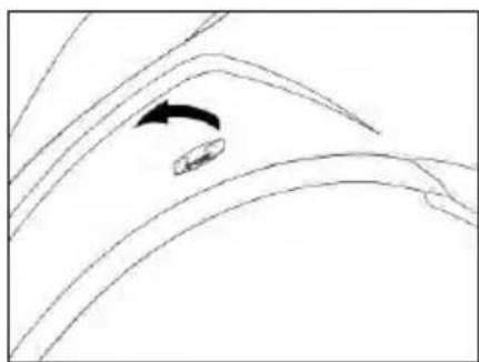
Fig. 2

Fig. 3

Fig. 4

Fig. 5
Fig. 6

Fig. 7
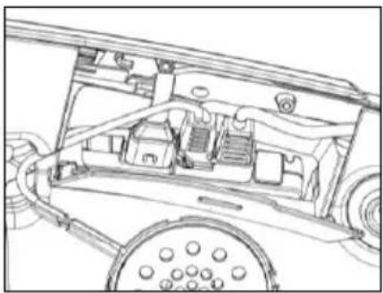
Fig. 8

Fig. 9
Fig. 10

Fig. 11
3.3. Mikrofon plassering
KUN FOR X-1005
Fig. 2
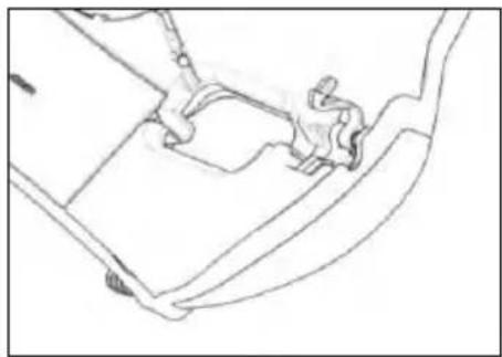
Fig. 13
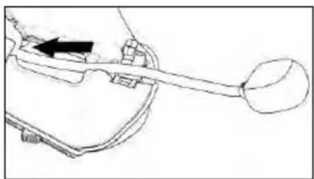
Fig. 14

Fig. 15
KUN FOR HJELMEN X-903, X-552
Fig. 16

Fig. 17

Fig. 17B
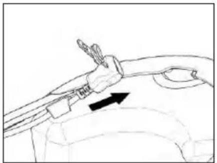
Fig. 18

Fig. 19
Fig. 20 - X-1005-HJELMEN

Fig. 21 - X-903-HJELMEN
Fig. 22

Fig. 23
Fig. 24
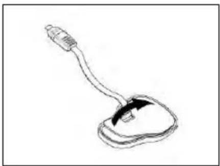
Fig. 25

Fig. 26

Fig. 27
Fig. 28

Fig. 29

Fig. 30

Fig. 31
Fig. 32
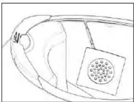
Fig. 33
GJELDER KUN HELHJELMER: Tre hakestroppen gjennom hullet i polystyrenputen.

Fig. 34
- Plasser batteriets koplingsstykke bakom polystyrenputen.
- Plasser kabelen i den fremre delen av hjelmen (Fig. 34).
4.3. Mikrofonplassering
HJELMER SOM KAN ÅPNES ELLER JET
Fig. 35

Fig. 36

Fig. 37
Fig. 38

Fig. 39
Fig. 40

Fig. 41
3 blink = medium, 30 \~ 70%
2 blink = lav, 0 \~ 30%
Umiddelbar stemme-indikator
Når du skrur på systemet, hold "n" og "▲" inne samtidig i ca 3 sekunder inntil du hører 3 høye pipelyder. Det vil deretter være en stemmekontroll som angir batteri-nivået.
Derimot, om du slipper knappene så snart systemet har skrudd seg på, vil du ikke motta batteri-nivå via stemme-indikatoren.
Fig. 42
For å lade, koble systemet til en lader eller en USB-kontakt med strømføring ved hjelp av den medfølgende USB/USB-C ledningen.
Ladingen foregår på følgende måte:
This device complies with Part 15 of the FCC Rules. Operation is subject to the following two conditions: (1) this device may not cause harmful interference, and (2) this device must accept any interference received, including interference that may cause undesired operation of the device.
Changes or modifications not expressly approved by the party responsible for compliance could void the user's authority to operate the equipment.
NOTE: The manufacturer is not responsible for any radio or TV interference caused by unauthorized modifications to this equipment. Such modifications could void the user's authority to operate the equipment.
This equipment has been tested and found to comply with the limits for a Class B digital device, pursuant to part 15 of the FCC rules. These limits are designed to provide reasonable protection against harmful interference in a residential installation. This equipment generates, uses and can radiate radio frequency energy and, if not installed and used in accordance with the instructions, may cause harmful interference to radio communications. However, there is no guarantee that interference will not occur in a particular installation.
This model meets the government's requirements for exposure to radio waves. Your wireless device is a radio transmitter and receiver. It is designed and manufactured not to exceed limits for exposure to radio frequency (RF) energy set by the Federal Communications Commission (FCC) of the U.S. Government and by the Canadian regulatory authorities.
The exposure standard for wireless mobile devices employs a unit of measurement known as the Specific Absorption Rate, or SAR. The SAR limit set by the FCC and by the Canadian regulatory authorities is 1.6 W/kg.1.
For Canada market only:
This EUT is compliant with SAR for general population/uncontrolled exposure limits in IC RSS-247. The N-Com electronic device is positioned on a minimum distance of - see the table below - from the head of the user, therefore no SAR test have been conducted on the product.
| N-COM SYSTEM | DISTANCE FROM THE HEAD |
| B902L R/B902 R | 30.00 mm |
| B602 R | 30.63 mm |
| B101 R | 30.63 mm |
| B902 X | 32.50 mm |
| B602 X | 34.50 mm |
POUR LE MARCHE US ET CANADIEN UNIQUEMENT: MISE EN GARDE SPECIALE
12.1.Koivn'xphon mousiukh meos Bluetooth (A2DP Sharing) 24
Eik. 1

Eik. 2
Eik. 3

Euk. 4

Elk. 5
Eik. 6
Elk. 7

Eik. 8

Eik. 9
Eik. 10

Elk. 11
Eik. 12

Elk. 13

Eik. 14

Elk. 15
Fig. 16

Fig. 17

Fig. 17B
Eik. 18
Eik. 19
Eik. 20 - X-1005

Eik. 21 - X-903
Eik. 22

Eik. 23
Eik. 24

Eik. 25

Eik. 26

Eik. 27
Eik. 28

Eik. 29

Eik. 30

Eik. 31
Eik. 32

Eik. 33
Eik. 34
Eik. 35
Eik. 36

Eik. 37
Eik. 38

Eik. 39
Eik. 40
Eik. 41
This device complies with Part 15 of the FCC Rules. Operation is subject to the following two conditions: (1) this device may not cause harmful interference, and (2) this device must accept any interference received, including interference that may cause undesired operation of the device.
Changes or modifications not expressly approved by the party responsible for compliance could void the user's authority to operate the equipment.
NOTE: The manufacturer is not responsible for any radio or TV interference caused by unauthorized modifications to this equipment. Such modifications could void the user's authority to operate the equipment.
This equipment has been tested and found to comply with the limits for a Class B digital device, pursuant to part 15 of the FCC rules. These limits are designed to provide reasonable protection against harmful interference in a residential installation. This equipment generates, uses and can radiate radio frequency energy and, if not installed and used in accordance with the instructions, may cause harmful interference to radio communications. However, there is no guarantee that interference will not occur in a particular installation.
This model meets the government's requirements for exposure to radio waves. Your wireless device is a radio transmitter and receiver. It is designed and manufactured not to exceed limits for exposure to radio frequency (RF) energy set by the Federal Communications Commission (FCC) of the U.S. Government and by the Canadian regulatory authorities.
The exposure standard for wireless mobile devices employs a unit of measurement known as the Specific Absorption Rate, or SAR. The SAR limit set by the FCC and by the Canadian regulatory authorities is 1.6 W/kg.1.
For Canada market only:
This EUT is compliant with SAR for general population/uncontrolled exposure limits in IC RSS-247. The N-Com electronic device is positioned on a minimum distance of - see the table below - from the head of the user, therefore no SAR test have been conducted on the product.
| N-COM SYSTEM | DISTANCE FROM THE HEAD |
| B902L R/B902 R | 30.00 mm |
| B602 R | 30.63 mm |
| B101 R | 30.63 mm |
| B902 X | 32.50 mm |
| B602 X | 34.50 mm |
POUR LE MARCHE US ET CANADIEN UNIQUEMENT: MISE EN GARDE SPECIALE
Fig. 1

Fig. 2

Fig. 3

Fig. 4

Fig. 5
Fig. 6

Fig. 7

Fig. 8

Fig. 9
Fig. 10

Fig. 11
Fig. 12

Fig. 13

Fig. 14

Fig. 15
UDELUKKENDE FOR HJELMEN X-903, X-552
Fig. 16

Fig. 17

Fig. 17B
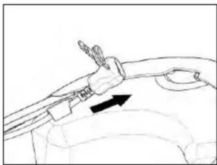
Fig. 18

Fig. 19
Fig. 20 - HJELMEN X-1005

Fig. 22

Fig. 23
Fig. 24
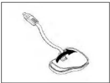
Fig. 25

Fig. 26

Fig. 27
Fig. 28

Fig. 29

Fig. 30

Fig. 31
Fig. 32

Fig. 33
Fig. 34
- Placer batteristikket bag ved polystyrepuden.
- Anbring kabelføringen i hjelmens bagerste side (Fig. 34).
Fig. 35

Fig. 36

Fig. 37
Fig. 38
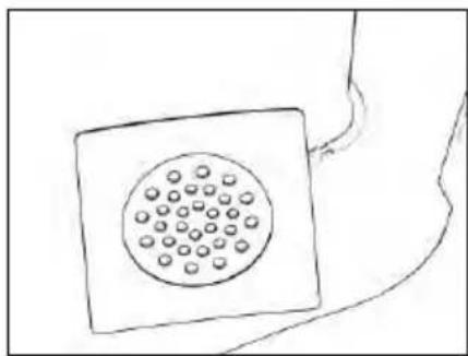
Fig. 39
Fig. 40

Fig. 41
This device complies with Part 15 of the FCC Rules. Operation is subject to the following two conditions: (1) this device may not cause harmful interference, and (2) this device must accept any interference received, including interference that may cause undesired operation of the device.
Changes or modifications not expressly approved by the party responsible for compliance could void the user's authority to operate the equipment.
NOTE: The manufacturer is not responsible for any radio or TV interference caused by unauthorized modifications to this equipment. Such modifications could void the user's authority to operate the equipment.
This equipment has been tested and found to comply with the limits for a Class B digital device, pursuant to part 15 of the FCC rules. These limits are designed to provide reasonable protection against harmful interference in a residential installation. This equipment generates, uses and can radiate radio frequency energy and, if not installed and used in accordance with the instructions, may cause harmful interference to radio communications. However, there is no guarantee that interference will not occur in a particular installation.
This model meets the government's requirements for exposure to radio waves. Your wireless device is a radio transmitter and receiver. It is designed and manufactured not to exceed limits for exposure to radio frequency (RF) energy set by the Federal Communications Commission (FCC) of the U.S. Government and by the Canadian regulatory authorities.
The exposure standard for wireless mobile devices employs a unit of measurement known as the Specific Absorption Rate, or SAR. The SAR limit set by the FCC and by the Canadian regulatory authorities is 1.6 W/kg.1.
For Canada market only:
This EUT is compliant with SAR for general population/uncontrolled exposure limits in IC RSS-247. The N-Com electronic device is positioned on a minimum distance of - see the table below - from the head of the user, therefore no SAR test have been conducted on the product.
| N-COM SYSTEM | DISTANCE FROM THE HEAD |
| B902L R/B902 R | 30.00 mm |
| B602 R | 30.63 mm |
| B101 R | 30.63 mm |
| B902 X | 32.50 mm |
| B602 X | 34.50 mm |
POUR LE MARCHE US ET CANADIEN UNIQUEMENT: MISE EN GARDE SPECIALE
6. PERUSTOIMINNOT 16
8. CONFIGURE-VALIKKO....20
9. PUHELIMEN/MP3-SOITTIMEN LAITEPARIN MUODOSTUS....21
10. TOISEN PUHELIMEN LAITEPARIN MUODOSTUS 21
11. MATKAPUHELIN....22
11.1.Pikavalinta....22
11.2.Puhelinneuvottelutoiminto 23
11.3.Smart Navi System....23
12. MUSIIKKI BLUETOOTHIN VÄLITYKSELLÄ....24
e-box ja johdot

Mikrofoni

Ladattava akku

USB-C kaapeli

Avain

Mutteri ja ruuvi
3. X-1005, X-903, X-552-KYPÄRÄN ASENNUS
Kuva 1

Kuva 2

Kuva 3

Kuva 4
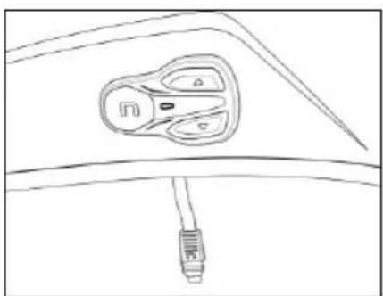
Kuva 5
Kuva 6

Kuva 7

Kuva 8

Kuva 9
Kuva 10

Kuva 11
3.3. Mikrofonin asetus
KOSKEE VAIN KYPÄRÄÄ X-1005
Kuva 12

Kuva 13

Kuva 14

Kuva 15
KOSKEE VAIN KYPÄRÄÄ X-903, X-552
Kuva 16

Kuva 17

Kuva 17B

Kuva 18

Kuva 19
Kuva 22
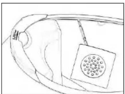
Kuva 23
Kuva 24
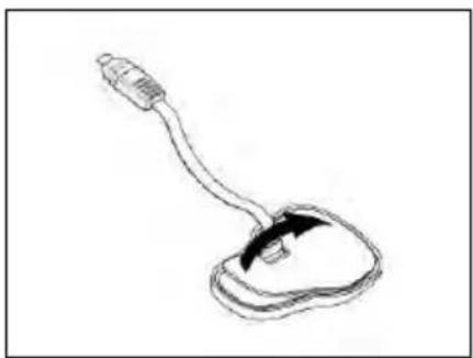
Kuva 25
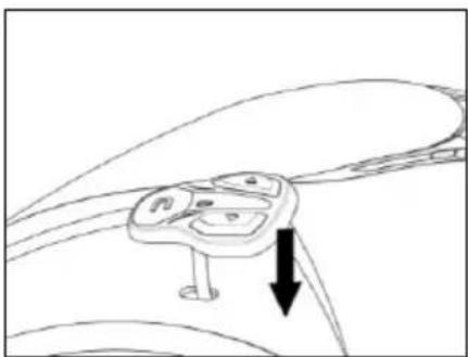
Kuva 26

Kuva 27
Kuva 28

Kuva 29

Kuva 30

Kuva 31
Fig. 32

Fig. 33
Kuva 34
Kuva 35
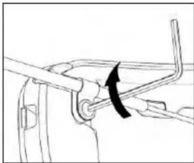
Kuva 36

Kuva 37
Kuva 38
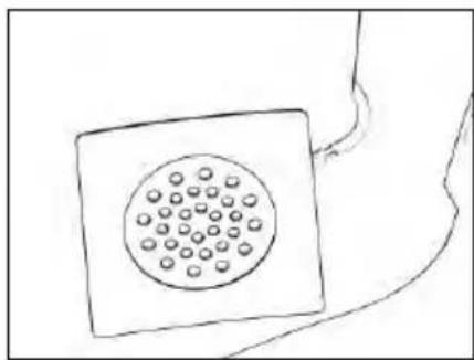
Kuva 39
Kuva 40

Kuva 41
Kuva 42
This device complies with Part 15 of the FCC Rules. Operation is subject to the following two conditions: (1) this device may not cause harmful interference, and (2) this device must accept any interference received, including interference that may cause undesired operation of the device.
Changes or modifications not expressly approved by the party responsible for compliance could void the user's authority to operate the equipment.
NOTE: The manufacturer is not responsible for any radio or TV interference caused by unauthorized modifications to this equipment. Such modifications could void the user's authority to operate the equipment.
This equipment has been tested and found to comply with the limits for a Class B digital device, pursuant to part 15 of the FCC rules. These limits are designed to provide reasonable protection against harmful interference in a residential installation. This equipment generates, uses and can radiate radio frequency energy and, if not installed and used in accordance with the instructions, may cause harmful interference to radio communications. However, there is no guarantee that interference will not occur in a particular installation.
This model meets the government's requirements for exposure to radio waves. Your wireless device is a radio transmitter and receiver. It is designed and manufactured not to exceed limits for exposure to radio frequency (RF) energy set by the Federal Communications Commission (FCC) of the U.S. Government and by the Canadian regulatory authorities.
The exposure standard for wireless mobile devices employs a unit of measurement known as the Specific Absorption Rate, or SAR. The SAR limit set by the FCC and by the Canadian regulatory authorities is 1.6 W/kg.1.
For Canada market only:
This EUT is compliant with SAR for general population/uncontrolled exposure limits in IC RSS-247. The N-Com electronic device is positioned on a minimum distance of - see the table below - from the head of the user, therefore no SAR test have been conducted on the product.
| N-COM SYSTEM | DISTANCE FROM THE HEAD |
| B902L R/B902 R | 30.00 mm |
| B602 R | 30.63 mm |
| B101 R | 30.63 mm |
| B902 X | 32.50 mm |
| B602 X | 34.50 mm |
POUR LE MARCHE US ET CANADIEN UNIQUEMENT: MISE EN GARDE SPECIALE
Fig. 1

Fig. 2

Fig. 3
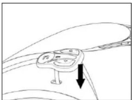
Fig. 4

Fig. 5
Fig. 6

Fig. 7

Fig. 8
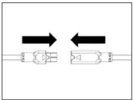
Fig. 9
Fig. 10

Fig. 11
Fig. 12
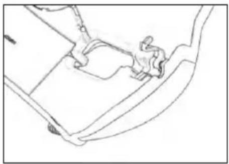
Fig. 13
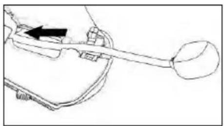
Fig. 14

Fig. 15
SOMENTE PARA CAPACETES X-903, X-552
Fig. 16
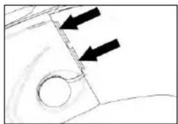
Fig. 17

Fig. 17B

Fig. 18

Fig. 19
Fig. 20 - CAPACETE X-1005

Fig. 21 - CAPACETE X-903
Fig. 22

Fig. 23
Fig. 24

Fig. 25

Fig. 26
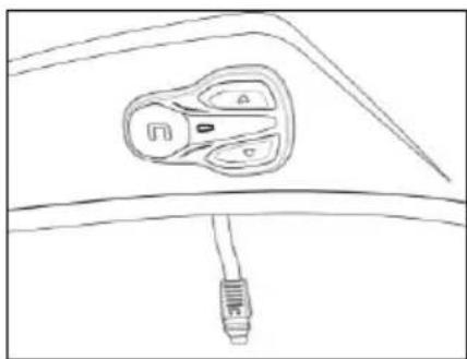
Fig. 27
Fig. 28

Fig. 29

Fig. 30
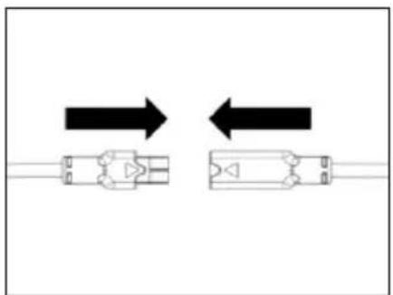
Fig. 31
Fig. 32
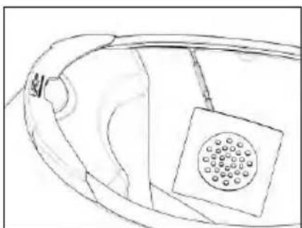
Fig. 33
Fig. 34
Fig. 35

Fig. 36

Fig. 37
Fig. 38

Fig. 39
4.4. Reposicionamento do enchimento
Fig. 40

Fig. 41
H. Apagar todas as conexões
This device complies with Part 15 of the FCC Rules. Operation is subject to the following two conditions: (1) this device may not cause harmful interference, and (2) this device must accept any interference received, including interference that may cause undesired operation of the device.
Changes or modifications not expressly approved by the party responsible for compliance could void the user's authority to operate the equipment.
NOTE: The manufacturer is not responsible for any radio or TV interference caused by unauthorized modifications to this equipment. Such modifications could void the user's authority to operate the equipment.
This equipment has been tested and found to comply with the limits for a Class B digital device, pursuant to part 15 of the FCC rules. These limits are designed to provide reasonable protection against harmful interference in a residential installation. This equipment generates, uses and can radiate radio frequency energy and, if not installed and used in accordance with the instructions, may cause harmful interference to radio communications. However, there is no guarantee that interference will not occur in a particular installation.
This model meets the government's requirements for exposure to radio waves. Your wireless device is a radio transmitter and receiver. It is designed and manufactured not to exceed limits for exposure to radio frequency (RF) energy set by the Federal Communications Commission (FCC) of the U.S. Government and by the Canadian regulatory authorities.
The exposure standard for wireless mobile devices employs a unit of measurement known as the Specific Absorption Rate, or SAR. The SAR limit set by the FCC and by the Canadian regulatory authorities is 1.6 W/kg.1.
For Canada market only:
This EUT is compliant with SAR for general population/uncontrolled exposure limits in IC RSS-247. The N-Com electronic device is positioned on a minimum distance of - see the table below - from the head of the user, therefore no SAR test have been conducted on the product.
| N-COM SYSTEM | DISTANCE FROM THE HEAD |
| B902L R/B902 R | 30.00 mm |
| B602 R | 30.63 mm |
| B101 R | 30.63 mm |
| B902 X | 32.50 mm |
| B602 X | 34.50 mm |
POUR LE MARCHE US ET CANADIEN UNIQUEMENT: MISE EN GARDE SPECIALE
Fig. 1

Fig. 2

Fig. 3

Fig. 4

Fig. 5
Fig. 6

Fig. 7

Fig. 8

Fig. 9
Fig. 10

Fig. 11
Fig. 12

Fig. 13

Fig. 14

Fig. 15
ALLEEN VOOR HELM X-903, X-552
Fig. 16

Fig. 17

Fig. 17B

Fig. 18

Fig. 19
Fig. 20 - HELM X-1005
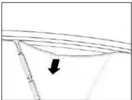
Fig. 21 - HELM X-903
Fig. 22

Fig. 23
Fig. 24

Fig. 25

Fig. 26
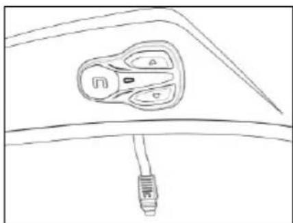
Fig. 27
Fig. 28
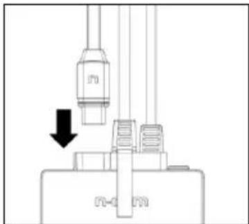
Fig. 29

Fig. 30

Fig. 31
Fig. 32

Fig. 33
Fig. 34
Fig. 35

Fig. 36
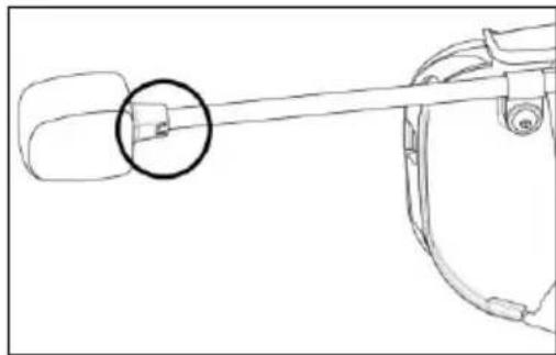
Fig. 37
Fig. 38

Fig. 39
4.4. Herpositionering van de bekleding
Fig. 40

Fig. 41
Fig. 42
This device complies with Part 15 of the FCC Rules. Operation is subject to the following two conditions: (1) this device may not cause harmful interference, and (2) this device must accept any interference received, including interference that may cause undesired operation of the device.
Changes or modifications not expressly approved by the party responsible for compliance could void the user's authority to operate the equipment.
NOTE: The manufacturer is not responsible for any radio or TV interference caused by unauthorized modifications to this equipment. Such modifications could void the user's authority to operate the equipment.
This equipment has been tested and found to comply with the limits for a Class B digital device, pursuant to part 15 of the FCC rules. These limits are designed to provide reasonable protection against harmful interference in a residential installation. This equipment generates, uses and can radiate radio frequency energy and, if not installed and used in accordance with the instructions, may cause harmful interference to radio communications. However, there is no guarantee that interference will not occur in a particular installation.
This model meets the government's requirements for exposure to radio waves. Your wireless device is a radio transmitter and receiver. It is designed and manufactured not to exceed limits for exposure to radio frequency (RF) energy set by the Federal Communications Commission (FCC) of the U.S. Government and by the Canadian regulatory authorities.
The exposure standard for wireless mobile devices employs a unit of measurement known as the Specific Absorption Rate, or SAR. The SAR limit set by the FCC and by the Canadian regulatory authorities is 1.6 W/kg.1.
For Canada market only:
This EUT is compliant with SAR for general population/uncontrolled exposure limits in IC RSS-247. The N-Com electronic device is positioned on a minimum distance of - see the table below - from the head of the user, therefore no SAR test have been conducted on the product.
| N-COM SYSTEM | DISTANCE FROM THE HEAD |
| B902L R/B902 R | 30.00 mm |
| B602 R | 30.63 mm |
| B101 R | 30.63 mm |
| B902 X | 32.50 mm |
| B602 X | 34.50 mm |
POUR LE MARCHE US ET CANADIEN UNIQUEMENT: MISE EN GARDE SPECIALE
4. INSTALLATION I HJÄLMARNA X-LITE....12
Fig. 1

Fig. 2
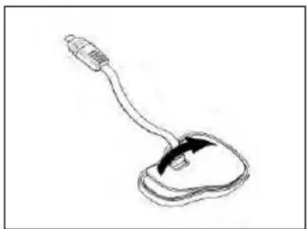
Fig. 3

Fig. 4

Fig. 5
Fig. 6

Fig. 7

Fig. 8
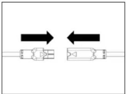
Fig. 9
Fig. 10
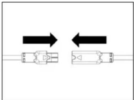
Fig. 11
3.3. Placering av mikrofonen
ENDAST FÖR HJÄLM X-1005
Fig. 12

Fig. 13

Fig. 14

Fig. 15
ENDAST FÖR HJÄLM X-903, X-552
Fig. 16
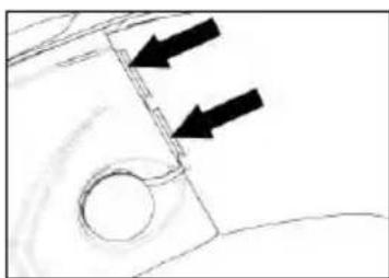
Fig. 17
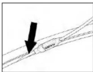
Fig. 17B

Fig. 18

Fig. 19
Fig. 20 – HJÄLM X-1005

Fig. 21 – HJÄLM X-903
Fig. 22

Fig. 23
4. INSTALLATION | HJÄLMARNA X-LITE
Fig. 24

Fig. 25

Fig. 26
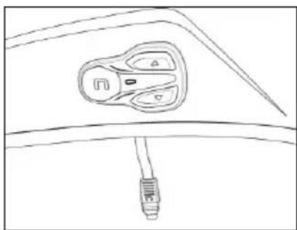
Fig. 27
Fig. 28

Fig. 29

Fig. 30

Fig. 31
Fig. 32

Fig. 33
BARA FÖR HELA HJÄLMAR: Sätt i bandet under haken i hålet på kindkuddspartiet.

Fig. 34
Fig. 35

Fig. 36

Fig. 37
Fig. 38

Fig. 39
Fig. 40

Fig. 41
This device complies with Part 15 of the FCC Rules. Operation is subject to the following two conditions: (1) this device may not cause harmful interference, and (2) this device must accept any interference received, including interference that may cause undesired operation of the device.
Changes or modifications not expressly approved by the party responsible for compliance could void the user's authority to operate the equipment.
NOTE: The manufacturer is not responsible for any radio or TV interference caused by unauthorized modifications to this equipment. Such modifications could void the user's authority to operate the equipment.
This equipment has been tested and found to comply with the limits for a Class B digital device, pursuant to part 15 of the FCC rules. These limits are designed to provide reasonable protection against harmful interference in a residential installation. This equipment generates, uses and can radiate radio frequency energy and, if not installed and used in accordance with the instructions, may cause harmful interference to radio communications. However, there is no guarantee that interference will not occur in a particular installation.
This model meets the government's requirements for exposure to radio waves. Your wireless device is a radio transmitter and receiver. It is designed and manufactured not to exceed limits for exposure to radio frequency (RF) energy set by the Federal Communications Commission (FCC) of the U.S. Government and by the Canadian regulatory authorities.
The exposure standard for wireless mobile devices employs a unit of measurement known as the Specific Absorption Rate, or SAR. The SAR limit set by the FCC and by the Canadian regulatory authorities is 1.6 W/kg.1.
For Canada market only:
This EUT is compliant with SAR for general population/uncontrolled exposure limits in IC RSS-247. The N-Com electronic device is positioned on a minimum distance of - see the table below - from the head of the user, therefore no SAR test have been conducted on the product.
| N-COM SYSTEM | DISTANCE FROM THE HEAD |
| B902L R/B902 R | 30.00 mm |
| B602 R | 30.63 mm |
| B101 R | 30.63 mm |
| B902 X | 32.50 mm |
| B602 X | 34.50 mm |
POUR LE MARCHE US ET CANADIEN UNIQUEMENT: MISE EN GARDE SPECIALE
Sl. 1
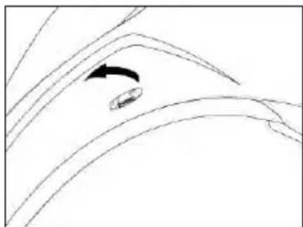
Sl. 2

Sl. 3
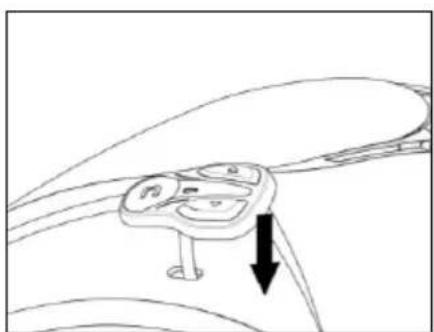
Sl. 4

Sl. 5
Opomba: Pazite, da ne boste kabla tipkovnice zalepili pod tipkovnico.
Opomba: V primeru, da tipkovnice niste pravilno namestili, jo takoj in zelo pazljivo odlepite ter ponovite postopek nameščanja.
Sl. 6

Sl. 7
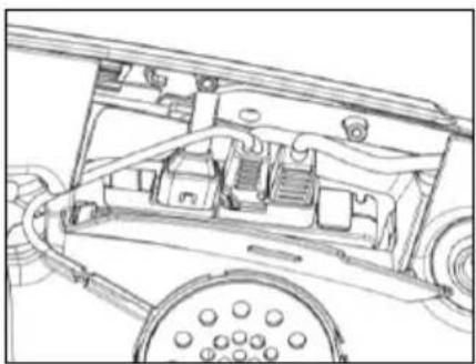
Sl. 8

Sl. 9
Sl. 10

Sl. 11
Sl. 12

Sl. 13

Sl. 14
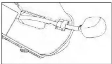
Sl. 15
SAMO ZA ČELADE MODELA X-903, X-552
Sl. 16

Sl. 17
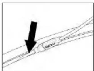
SI. 17B

Sl. 18
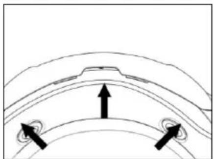
Sl. 19
Sl. 20 – ČELADA X-1005

SI. 21 – ČELADA X-903
- Na desni strani čelade umaknite plastično oblogo nastavka lične blazinice in vstavite baterijo v pripravljeno ohišje (Sl. 20/21 - 22).
SAMO ZA ČELADE MODELA
Sl. 22

Sl. 23
Sl. 24

Sl. 25

Sl. 26

Sl. 27
- Prilepite tipkovnico na školjko čelade in pritisnite nanjo po vsej površini, da se dobro prilepi (Sl. 27).
Opomba: Pazite, da ne boste kabla tipkovnice zalepili pod tipkovnico.
Opomba: V primeru, da tipkovnice niste namestili pravilno, jo takoj in zelo pazljivo odlepite ter ponovite postopek nameščanja.
Sl. 28

Sl. 29
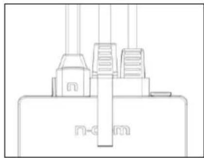
SI. 30
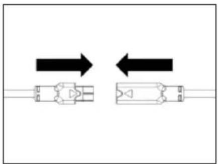
Sl. 31
Sl. 32

Sl. 33
SAMO ZA INTEGRALNO ZAPRTE ČELADE: Podbradni pas povlecite skozi odprtino v polistirenskem nastavku obrazne blazinice.

Sl. 34
- Baterijski konektor namestite za polistirenski nastavek obrazne blazinice.
- Ožičenje namestite pod spodnjo obrobo na temenskem delu čelade (Sl. 34).
4.3. Montaža mikrofona
ODPRTE - JET ČELADE
Sl. 35

Sl. 36
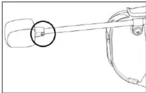
Sl. 37
Sl. 38

Sl. 39
Sl. 40

Sl. 41
Sl. 42
This device complies with Part 15 of the FCC Rules. Operation is subject to the following two conditions: (1) this device may not cause harmful interference, and (2) this device must accept any interference received, including interference that may cause undesired operation of the device.
Changes or modifications not expressly approved by the party responsible for compliance could void the user's authority to operate the equipment.
NOTE: The manufacturer is not responsible for any radio or TV interference caused by unauthorized modifications to this equipment. Such modifications could void the user's authority to operate the equipment.
This equipment has been tested and found to comply with the limits for a Class B digital device, pursuant to part 15 of the FCC rules. These limits are designed to provide reasonable protection against harmful interference in a residential installation. This equipment generates, uses and can radiate radio frequency energy and, if not installed and used in accordance with the instructions, may cause harmful interference to radio communications. However, there is no guarantee that interference will not occur in a particular installation.
This model meets the government's requirements for exposure to radio waves. Your wireless device is a radio transmitter and receiver. It is designed and manufactured not to exceed limits for exposure to radio frequency (RF) energy set by the Federal Communications Commission (FCC) of the U.S. Government and by the Canadian regulatory authorities.
The exposure standard for wireless mobile devices employs a unit of measurement known as the Specific Absorption Rate, or SAR. The SAR limit set by the FCC and by the Canadian regulatory authorities is 1.6 W/kg.1.
For Canada market only:
This EUT is compliant with SAR for general population/uncontrolled exposure limits in IC RSS-247. The N-Com electronic device is positioned on a minimum distance of - see the table below - from the head of the user, therefore no SAR test have been conducted on the product.
| N-COM SYSTEM | DISTANCE FROM THE HEAD |
| B902L R/B902 R | 30.00 mm |
| B602 R | 30.63 mm |
| B101 R | 30.63 mm |
| B902 X | 32.50 mm |
| B602 X | 34.50 mm |
POUR LE MARCHE US ET CANADIEN UNIQUEMENT: MISE EN GARDE SPECIALE
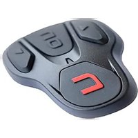
- SOLO PER CASCHI X-903, X-552
- FOR CANADA MARKET ONLY
- POUR LE MARCHE US ET CANADIEN UNIQUEMENT: MISE EN GARDE SPECIALE
- USER INSTRUCTIONS AND SAFETY
- CONTENTS
- WARNINGS AND SAFETY 5
- CONTENT OF THE PACKAGING 7
- INSTALLATION ON THE X-1005, X-903, X-552 HELMET 8
- INSTALLATION ON THE X-LITE HELMETS....12
- REMOVING THE SYSTEM....15
- BASIC FUNCTIONS....16
- PAIRING MODE 19
- CONFIGURATION MENU....20
- MOBILE PHONE / MP3 PLAYER PAIRING....21
- SECOND MOBILE PHONE PAIRING....21
- MOBILE PHONE 22
- MUSIC VIA BLUETOOTH....24
- GPS PAIRING....24
- INTERCOM RIDER-PASSENGER....25
- UNIVERSAL INTERCOM" INTERCOM....26
- REMOTE CONTROL....27
- BATTERY AND RECHARGE....28
- SUMMARY TABLE OF CONTROLS 29
- WARRANTY 31
- WARNINGS AND SAFETY
- ROAD SAFETY
- SWITCHING ON THE SYSTEM IN SAFE ENVIRONMENTS
- INTERFERENCES
- APPROPRIATE USE
- QUALIFIED PERSONNEL
- ACCESSORIES AND BATTERIES
- DISPOSAL
- CONTENT OF THE PACKAGING
- INSTALLATION ON THE X-1005, X-903, X-552 HELMET
- PRELIMINARY OPERATIONS
- INSTALLING THE SYSTEM IN THE X-1005, X-903, X-552 HELMETS
- MICROPHONE POSITIONING
- ONLY FOR X-1005 HELMETS
- ONLY FOR X-903, X-552 HELMETS
- REPOSITIONING THE PADDING
- INSTALLATION ON THE X-LITE HELMETS
- INSTALLING THE SYSTEM IN THE HELMET
- FLIP UP OR JET HELMETS
- FULL-FACE HELMETS
- REMOVING THE SYSTEM
- BASIC FUNCTIONS
- COMPLETE MODE AND SIMPLE MODE
- VIA THE N-COM SYSTEM
- VIA THE N-COM EASYSET APP
- VIA YOUR COMPUTER USING THE N-COM EASYSET PROGRAM
- VOLUME ADJUSTMENT
- AUTO OFF FUNCTION
- MULTI-LANGUAGE VOICE MESSAGES
- VIA THE SMARTPHONE N-COM EASYSET APP
- N-COM EASYSET
- UPDATING THE FIRMWARE
- PAIRING MODE
- PAIRING MENU
- EXITING THE CONFIGURATION
- MOBILE PHONE / MP3 PLAYER PAIRING
- SECOND MOBILE PHONE PAIRING
- MOBILE PHONE
- SPEED DIAL
- SAVING THE SPEED DIAL NUMBERS
- USING THE STORED NUMBERS
- CONFERENCE CALL FUNCTION
- SMART NAVI SYSTEM
- SHARING MUSIC VIA BLUETOOTH (A2DP SHARING)
- GPS PAIRING
- INTERCOM RIDER-PASSENGER
- N-COM "600"/"800"/"900" SERIES INTERCOM PAIRING
- PAIRING WITH OTHER N-COM SYSTEMS
- INTERCOM FUNCTION
- UNIVERSAL INTERCOM" INTERCOM
- PAIRING WITH THE UNIVERSAL INTERCOM
- UNIVERSAL INTERCOM FUNCTION
- FROM THE N-COM B602 SYSTEM
- FROM INTERCOM B
- N.B
- REMOTE CONTROL
- BATTERY AND RECHARGE
- LOW BATTERY SIGNAL
- CHECKING THE BATTERY LEVEL
- LED INDICATOR
- VOCAL INDICATOR
- CHARGING THE SYSTEM
- SUMMARY TABLE OF CONTROLS
- WARRANTY
- WE KINDLY ASK YOU TO
- WARRANTY COVERAGE AND VALIDITY
- EXCLUSIONS AND LIMITATIONS OF COVERAGE
- PROCEDURE FOR SUBMITTING CLAIMS
- PRODUCT IDENTIFICATION
- FOR USA AND CANADA MARKET ONLY: SPECIAL WARNING
- UNIQUEMENT POUR CASQUE X-903, X-552
- INSTRUCTIONS VOCALES
- NUR FÜR DEN X-903, X-552 -HELM
- SOLO PARA CASCO X-903, X-552
- INNHOLDET I ESKEN....7
- INSTALLERING INN I HJELM X-1005, X-903, X-552....8
- INNHOLDET I ESKEN
- MIKROFON PLASSERING
- KUN FOR X-1005
- KUN FOR HJELMEN X-903, X-552
- MIKROFONPLASSERING
- HJELMER SOM KAN ÅPNES ELLER JET
- UMIDDELBAR STEMME-INDIKATOR
- UDELUKKENDE FOR HJELMEN X-903, X-552
- PERUSTOIMINNOT 16
- CONFIGURE-VALIKKO....20
- PUHELIMEN/MP3-SOITTIMEN LAITEPARIN MUODOSTUS....21
- TOISEN PUHELIMEN LAITEPARIN MUODOSTUS 21
- MATKAPUHELIN....22
- MUSIIKKI BLUETOOTHIN VÄLITYKSELLÄ....24
- X-1005, X-903, X-552-KYPÄRÄN ASENNUS
- MIKROFONIN ASETUS
- KOSKEE VAIN KYPÄRÄÄ X-1005
- KOSKEE VAIN KYPÄRÄÄ X-903, X-552
- SOMENTE PARA CAPACETES X-903, X-552
- REPOSICIONAMENTO DO ENCHIMENTO
- ALLEEN VOOR HELM X-903, X-552
- HERPOSITIONERING VAN DE BEKLEDING
- INSTALLATION I HJÄLMARNA X-LITE....12
- PLACERING AV MIKROFONEN
- ENDAST FÖR HJÄLM X-1005
- ENDAST FÖR HJÄLM X-903, X-552
- INSTALLATION | HJÄLMARNA X-LITE
- SAMO ZA ČELADE MODELA X-903, X-552
- SAMO ZA ČELADE MODELA
- MONTAŽA MIKROFONA
- ODPRTE - JET ČELADE
Brand : Nolan
Model : N-com B602 X
Category : Headset