
ELECTRONIC ALARM - Electronic alarm APRILIA - Free user manual and instructions
Find the device manual for free ELECTRONIC ALARM APRILIA in PDF.
| Product type | Electronic alarm for motorcycle |
| Brand | APRILIA |
| Model | ELECTRONIC ALARM |
| Power supply | Vehicle battery (12V) and rechargeable internal battery |
| Position sensor | Yes, detects variations > 1.5° on all axes |
| Integrated siren | Yes, with high and low pitch audible signal |
| LED indicator | Yes, indicates alarm status and Override code |
| Remote controls provided | 2, with possibility up to 6 |
| Remote control range | Approximately 10 meters (estimate) |
| Emergency deactivation code | Customizable 5-digit Override code |
| Programmable functions | Audible signal (buzzer) and turn signals (direction indicators) |
| Self-power | Yes, up to 9 alarm cycles (26 s sound, 15 s pause) |
| Stop mode | Yes, after 10 days without alarm to save battery |
| Alarm memory | Yes, indicates the cause via LED flashes |
| Protection | Position sensor (SP), seat (PS), ignition (TA), battery (CA) |
| Max number of alarms per cause | 10 |
| Remote control battery | CR2032 3V, code 222120050 |
| Compliance | FCC Part 15 |
| Central unit dimensions | Not provided |
| Weight | Not provided |
Frequently Asked Questions - ELECTRONIC ALARM APRILIA
User questions about ELECTRONIC ALARM APRILIA
0 question about this device. Answer the ones you know or ask your own.
Ask a new question about this device
Download the instructions for your Electronic alarm in PDF format for free! Find your manual ELECTRONIC ALARM - APRILIA and take your electronic device back in hand. On this page are published all the documents necessary for the use of your device. ELECTRONIC ALARM by APRILIA.
USER MANUAL ELECTRONIC ALARM APRILIA
Automatic saddle opening
Operating Instructions
Instructions de service
Bedienungsanweisung
Tested To Comply With FCC Standards
P3OS4911
Attenzione:
Congratulations! Your Aprilia has been fitted with a Meta System alarm system.
Any unauthorised attempt to move your motorcycle, start up its engine, open up the saddle or disconnect its battery will trigger an alarm.
It is important that you familiarise yourself with the features provided by the system; to do this, we recommend reading this manual, as it describes all the functions your alarm system is able to offer.
In case of doubt, please contact your Aprilia dealer.
Caution: The alarm system comes with a hard-wearing card known as the CODE CARD: this contains vital information for disarming the system (see the EMERGENCY DISARMING VIA THE OVERRIDE CODE section) and on duplicating new remote controls (see the DUPLICATING AND ENABLING REMOTE CONTROLS section).
Description and use of the codes shown on the CODE CARD:
Override Code: shown on the white label, next to "Company Code". It has 5 digits (these can be changed, see the CUSTOMISING THE OVERRIDE CODE section). You will need to use it if the remote control fails to operate for any reason (see the EMERGENCY DISARMING VIA THE OVERRIDE CODE section).
Alpha-numeric Code: shown on the yellow label underneath the bar code. It has 16 digits and will be needed by the Aprilia Service Centre if you want to order an extra remote control (see the DUPLICATING AND ENABLING REMOTE CONTROLS section). Lastly, the numbers from 1 to 6 represent the remote controls that the system is able to store in its memory: numbers 1 and 2 shown with an asterisk are those supplied with the alarm system as standard.
If you sell your motorcycle, remember to give the CODE CARD to the new owner. Should you lose or misplace your CODE CARD, you will have to have a complete new alarm system fitted.
INITIAL START-UP
Every time your vehicle's battery is disconnected, you will have to re-enable the alarm system by turning the ignition key (off-on-off). The system will be operational again once you have done this.
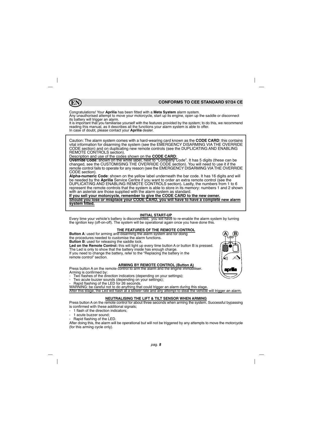
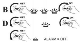
THE FEATURES OF THE REMOTE CONTROL
Button A: used for arming and disarming the alarm system and for doing the procedures needed to customise the alarm functions.
Button B: used for releasing the saddle lock.
Led on the Remote Control: this will light up every time button A or button B is pressed.
The Led is only to show that the battery inside has enough charge
If you need to change the battery, refer to the "Replacing the battery in the remote control" section.
ARMING BY REMOTE CONTROL (Button A)
Press button A on the remote control to arm the alarm and the engine immobiliser.
Arming is confirmed by:
-
Two flashes of the direction indicators (depending on your settings);
-
Two acute buzzer sounds (depending on your settings);
-
Rapid flashing of the LED for 26 seconds.
WARNING: be careful not to do anything that could trigger an alarm during this stage.
After this stage, the Led will flash at a slower rate and any attempt to steal the vehicle will trigger an alarm.
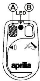
NEUTRALISING THE LIFT & TILT SENSOR WHEN ARMING
Press button A on the remote control for about three seconds when arming the system. Successful bypassing is confirmed with these additional signals;
-
1 flash of the direction indicators;
-
1 acute buzzer sound;
Rapid flashing of the LED.
After doing this, the alarm will be operational but will not be triggered by any attempts to move the motorcycle (for this arming cycle only).
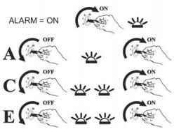
DISARMING BY REMOTE CONTROL
To disarm the alarm system, press the button on the remote control once. Disarming is confirmed by:
- One flash of the direction indicators (depending on your settings);
- One buzzer sound (depending on your settings)
- The LED stops flashing.
SADDLE RELEASE
You can access the storage underneath the saddle by pressing button B on the remote control.
This function can only be used when the status of the alarm system is as follows:
- Alarm system disarmed by remote control with the key in the OFF position.
- Alarm system disarmed with the key in the ON position for two minutes.
For security reasons
This function will be temporarily disabled should button B be pressed 10 times within the space of two minutes.
It will be accessible again after a pause of five minutes.
ELECTRONIC LIFT & TILT SENSOR
After the alarm system has been armed, the integrated lift & tilt sensor is able to detect any variation in its position exceeding 1.5^ on any of the axes.
This means your motorcycle is protected against attempts to lift it, take it off its stand or push it when the engine is not running.
If required, this function can be bypassed, as described in the "NEUTRALISING THE LIFT & TILT SENSOR WHEN ARMING" section.
CHECKING OPERATING STATUS
This function lets you check that the alarm protection is working correctly.
Arm the alarm system using the remote control. During the 26 second entry phase, turn the ignition key, move your motorcycle or lift up the saddle: the system should respond with a buzzer sound, confirming it is operating correctly, and the entry phase will start again from scratch.
Once the 26 second entry phase is over, any alarm trigger will provoke an acoustic alarm signal.
ALARM SIGNAL LIMITS
There can be a maximum of 10 alarm signals for each line of protection:
- Lift & tilt sensor (SP)
- Saddle protection (PS)
- Attempted ignition (TA)
- Current drop (CA)
MEMORISED ALARMS
If, after disarming, the alarm system emits a flat buzzer sound followed by the flashing of the LED, this means one or more alarms were triggered in your absence.
To identify what triggered the alarm system, refer to the table and the abbreviations shown in the box above.
The alarm will continue providing this information until you turn the ignition key or arm the alarm system again.
CAUSES
SP
PS
TA
CA
FLASHES
1 flash
2 flashes
3 flashes
4 flashes
REMOTE CONTROL PROGRAMMABLE FUNCTIONS
The manufacturer prepares the alarm system with standard settings (see table B).
You can alter its settings to meet your particular needs by following the procedure below:
1) Arm the system using the remote control.
2) Turn the ignition key to the ON position (+15). The alarm system will respond with an acute acoustic sound (beep).
3) Press button A on the remote control four times within 10^ . Every time you press the button you should see the direction indicators flash.
After you have pressed the remote control button for the fourth time, the alarm system will emit four flat sounds (boops) confirming it has entered programming mode. You can now select the function required.
4) Turn +15 on and off until you reach the number of the function required (see table A), e.g. Blinker - switch +15 off and on twice. The LED switches on every time +15 is on to facilitate counting.
5) Keeping +15 on, press button A once if you want to select the setting shown in the left hand column; press button A twice if you want to select the setting shown in the right hand column.
6) Switch +15 off and repeat the procedure from step 4 if you want to change any other settings.
IMPORTANT: after you have programmed in a setting, the counter always starts again from the first function.
7) Four fast buzzer sounds confirm the end of programming;
8) Press button A on the remote control once when the key is in the OFF position to exit programming mode altogether.
Table A Programming
| ONE PRESS OF THE BUTTON | TWO PRESS OF THE BUTTON | ||
| 1 | Buzzer | YES | NO |
| 2 | Blinker | YES | NO |
Table B Default settings
| 1 | Buzzer | YES |
| 2 | Blinker | YES |
Key of the functions that can be programmed in:
Buzzer = acoustic signalling of the arming and disarming of the alarm system.
Blinker = visual signalling of the arming and disarming of the alarm system
EMERGENCY DISARMING VIA THE OVERRIDE CODE
Should your remote control be stolen or misplaced, stop working, or have a flat battery, you can disarm your alarm system by following an emergency procedure using the 5-digit OVERRIDE code shown on the CODE CARD.
NB: THIS PROCEDURE WILL INEVITABLY TRIGGER AN ALARM AS IT INVOLVES USING THE IGNITION KEY.
Each product has a different, factory-set OVERRIDE code, but this may be changed to a code of your choice. (See the "CUSTOMISING THE OVERRIDE CODE" section)
Follow the procedure below in order to disarm the alarm system:
Turn the ignition key to the ON position (+15) and check that the LED is now lit without flashing;
A) Return the ignition key to the OFF position and wait for the LED to start flashing in order to confirm the first digit in the override code;
CAUTION: THE NUMBER OF FLASHES MUST MATCH THE FIRST DIGIT IN THE CODE (E.G. IF THE FIRST DIGIT IS 1, TUP THE KEY TO THE ON POSITION WHEN THE LED HAS FLASSED ONCE)
Confirm the digit by turning the key to the ON position;
OVERRIDE CODE EXAMPLE 13212
B) Return the ignition key to the OFF position and wait for the LED to start flashing in order to confirm the second digit; confirm the digit and repeat steps C-D and E for the remaining digits.
If you have entered the correct code, the alarm will be disarmed once you have confirmed the fifth digit. You must start up the engine to confirm the whole operation; if you fail to do this, the alarm will remain armed. In this case, you must repeat the whole procedure.
Caution: the control unit will enter a 30-minute block if incorrect codes are entered 3 times.
CUSTOMISING THE OVERRIDE CODE
You can customise the OVERRIDE code to a code of your choice by following the same procedure described above when the alarm system is disarmed:
Within 10 seconds, turn the ignition key from the OFF position to the ON position (+15) 3 consecutive times; the LED will light up without flashing and you will hear a buzzer sound by way of confirmation;
A) Return the ignition key to the OFF position and wait for the LED to start flashing in order to confirm the first digit in the override code. Confirm the digit by turning the key to the ON position (E.g.: if the first digit is 1, turn the key to the ON position when the led has flashed once);
B) Within 3" return the ignition key to the OFF position and wait for the LED to start flashing in order to confirm the second digit; confirm the digit and repeat steps C-D and E for the remaining digits. Once you have confirmed the fifth digit, leave the key in the ON position (+15): if you have entered the correct code, the alarm system will emit four dual-tone buzzer sounds and the LED will turn off.
ENTERING THE NEW CODE:
F) Return the ignition key to the OFF position and wait for the LED to start flashing in order to confirm the first digit in the new code;
G) Return the ignition key to the OFF position and wait for the LED to start flashing in order to confirm the second digit. Repeat steps H- I and L for the remaining digits;
Once you have confirmed the fifth digit in the new OVERRIDE code, the alarm system will emit four dual-tone buzzer sounds. Leave the key in the ON position for the new code entered to be displayed by way of a sequence of LED flashes after a 3" pause. It is important to wait for verification of the new code so you know immediately if any mistake was made when entering the digits.
NB: Make a note of the newly customised OVERRIDE code in the space provided on the printed form found on the last page of this manual. Cut out the page as shown and keep in a safe place.
DUPLICATING AND ENABLING REMOTE CONTROLS
The system is supplied with two remote controls and can accept up to a maximum of 6.
You must go to an authorised Aprilia service centre for this service: remember to take your CODE CARD with the 16-digit alpha-numerical code with you.
Your Aprilia service centre will order a new, pre-programmed remote control for you (it is essential to have the code shown on the Code Card). The customer or the Aprilia service centre can then pair up the new remote control, as described in the following procedure:
CAUTION: ALL THE WORKING REMOTE CONTROLS ARE NEEDED FOR COMPLETION OF THIS PROCEDURE; THERE MUST BE AT LEAST ONE REMOTE CONTROL IN WORKING ORDER.
Automatic pairing procedure:
1) Disarm the alarm system using the remote control.
2) Switch the instrument panel on (+15) three consecutive times within 3" until you see the LED is lit without flashing and hear an acute buzzer sound;
3) Enter the OVERRIDE code (see the EMERGENCY DISARMING VIA THE OVERRIDE CODE section) and leave the key in the ON position (+15) after the fifth digit.
If you have entered the correct code, the alarm system will emit two acute buzzer sounds (beeps) followed by two flat sounds (boops), confirming you have accessed the procedure.
4) Press the button on the new remote control until the alarm system LED lights up;
5) Press the button on the new remote control again and check that the LED now goes off followed by an acute buzzer sound: the alarm system has now stored the new remote control into its memory.
Repeat steps 4 and 5 to store all the remote controls you want the alarm system to recognise.
NB: This also includes any existing remote controls.
Exit the procedure by turning the key to the OFF position. The alarm system will now emit two acute buzzer sounds (beeps) and two flat sounds (boops) by way of confirmation.
NB: every time you take the key out of the ignition, the Led will flash the same number of times as the remote controls paired up with the system.
BATTERY BACK UP
The alarm system has its own integrated batteries and will trigger an alarm if its cables are cut or the vehicle's battery is disconnected.
If the battery connection is restored, the alarm will stop sounding 30" after it has been reconnected.
The battery back up safeguards up to 9 alarm cycles, sounding for 26" with a 15" pause.
The direction indicators do not operate when the alarm is operating on its battery back up supply. The battery back up is only operational when the alarm has been armed.
If the vehicle's power supply has been disconnected, the buzzer will sound during the entry phase to warn you and continue until the end of the entry phase. Afterwards, the alarm signal will continue with a dual tone sound.
THE E52 REMOTE CONTROL
This device complies with part 15 of FCC standards. Its operation is subject to the two following standards: (1) this appliance must not cause any harmful interference and (2) this appliance must accept any interference received, including interference which could cause it to operate improperly.

P3OS4911
Caution:
Any changes or modifications without specific authorisation by the person in charge of compliance may invalidate the consumer's right to use the appliance.

CAUTION "RISK OF EXPLOSION IF THE BATTERY IS REPLACED WITH THE INCORRECT TYPE. DISPOSE OF USED BATTERIES ACCORDING TO INSTRUCTIONS BELOW"
REPLACING THE BATTERY IN THE REMOTE CONTROL
When the battery is flat, please do not throw it away with your normal household waste; dispose of it in the special recycling bins.
To replace the battery, unscrew the screw on the back and separate the two shells. Take the flat battery out and put a new one in: make sure you insert the battery the right way up (see illustration).
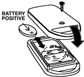
You should replace the battery with a new CR 2032 3V Lithium battery (item code 222120050).
STOP MODE
STOP MODE is used to reduce the chance of flattening your motorcycle battery.
This function enters operation when:
-
It has been more than 10 days since the alarm system was last armed using the remote control, or armed automatically, without any alarm being triggered;
-
The motorcycle's battery is becoming flat.
The alarm system "wakes up" out of STOP MODE when the ignition key is turned to the ON position. In this case, the alarm system returns to its previous status when it was last armed.
As soon as the ignition key is turned to the ON position, the buzzer will emit a series of acute sounds, lasting for 5^ , and will then start an alarm cycle. Press the remote control to disarm the alarm system.
ADDITIONAL FUNCTIONS
The system is able to monitor the status of the vehicle's battery and the alarm system's own internal battery used for its back up power supply (rechargeable but not replaceable) and will notify you with an acoustic warning signal.
Vehicle battery: battery maintenance is necessary if you hear 4 short warning signals after disarming the alarm system.
Internal battery (back up power supply): the internal battery needs charging up if you hear 4 short warning signals after arming the alarm system.
Use the vehicle to charge it up.
RECOMMENDATIONS
-
Do not leave remote controls where they can be damaged by high heat, water or impact.
-
After the product has been fitted, we recommend testing all of its functions on a regular basis by following the instructions in the CHECKING OPERATING STATUS section.
Contact a service centre in case of any malfunction or for any further information.
WARNING
This product is only a means of discouraging potential theft. It should not be considered any sort of insurance against theft. The manufacturer is not liable for any fault or operating failure of the product, of any of its accessories or of the vehicle's wiring system caused by improper use.
The manufacturer reserves the right to make any changes considered necessary at any time without notice.

CONFORME A LA DIRECTIVE CEE 97/24 CE
30033 Noale (VE) Italy
Tel. +39 041 5829111
Fax +39 041 441054
www.aprilia.com
Codice Override / Override Code Code Override / Override Codierung Cjdko Override
- Automatic saddle opening
- P3OS4911
- Attenzione:
- INITIAL START-UP
- THE FEATURES OF THE REMOTE CONTROL
- ARMING BY REMOTE CONTROL (Button A)
- NEUTRALISING THE LIFT & TILT SENSOR WHEN ARMING
- DISARMING BY REMOTE CONTROL
- SADDLE RELEASE
- For security reasons
- ELECTRONIC LIFT & TILT SENSOR
- CHECKING OPERATING STATUS
- ALARM SIGNAL LIMITS
- MEMORISED ALARMS
- CAUSES
- FLASHES
- REMOTE CONTROL PROGRAMMABLE FUNCTIONS
- EMERGENCY DISARMING VIA THE OVERRIDE CODE
- CUSTOMISING THE OVERRIDE CODE
- ENTERING THE NEW CODE:
- DUPLICATING AND ENABLING REMOTE CONTROLS
- CAUTION: ALL THE WORKING REMOTE CONTROLS ARE NEEDED FOR COMPLETION OF THIS PROCEDURE; THERE MUST BE AT LEAST ONE REMOTE CONTROL IN WORKING ORDER.
- BATTERY BACK UP
- THE E52 REMOTE CONTROL
- Caution:
- CAUTION "RISK OF EXPLOSION IF THE BATTERY IS REPLACED WITH THE INCORRECT TYPE. DISPOSE OF USED BATTERIES ACCORDING TO INSTRUCTIONS BELOW"
- REPLACING THE BATTERY IN THE REMOTE CONTROL
- STOP MODE
- ADDITIONAL FUNCTIONS
- RECOMMENDATIONS
- WARNING
- CONFORME A LA DIRECTIVE CEE 97/24 CE
Brand : APRILIA
Model : ELECTRONIC ALARM
Category : Electronic alarm