
RX 50 RACING - Motorcycle APRILIA - Free user manual and instructions
Find the device manual for free RX 50 RACING APRILIA in PDF.
User questions about RX 50 RACING APRILIA
0 question about this device. Answer the ones you know or ask your own.
Ask a new question about this device
Download the instructions for your Motorcycle in PDF format for free! Find your manual RX 50 RACING - APRILIA and take your electronic device back in hand. On this page are published all the documents necessary for the use of your device. RX 50 RACING by APRILIA.
USER MANUAL RX 50 RACING APRILIA
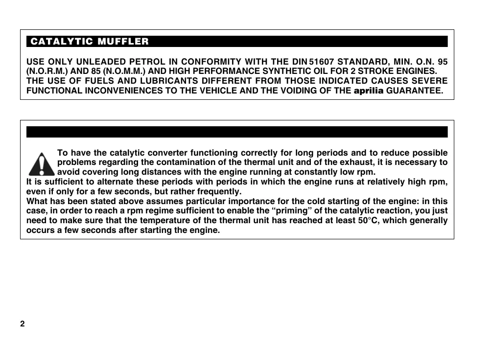
To have the catalytic converter functioning correctly for long periods and to reduce possible problems regarding the contamination of the thermal unit and of the exhaust, it is necessary to avoid covering long distances with the engine running at constantly low rpm.
It is sufficient to alternate these periods with periods in which the engine runs at relatively high rpm, even if only for a few seconds, but rather frequently.
What has been stated above assumes particular importance for the cold starting of the engine: in this case, in order to reach a rpm regime sufficient to enable the "priming" of the catalytic reaction, you just need to make sure that the temperature of the thermal unit has reached at least 50^ , which generally occurs a few seconds after starting the engine.
CATALYTIC SILENCER
The catalytic version of the RX50 Racign is fitted with a silencer with metal catalytic converter of the "platinum-rhodium bivalent" type. This device provides for the oxidation of the CO (carbon monoxide) and of the HC (unburned hydrocarbons) contained in the exhaust gases, changing them into carbon dioxide and steam, respectively. Due to the catalytic reaction, the high temperature reached by the exhaust gases results in the burning of the oil particles, thus keeping the silencer clean and eliminating the exhaust fumes.

Avoid parking the catalytic vehicle near dry brush wood or in places easily accessible to children, as the catalytic silencer becomes extremely hot during use; be very careful and avoid any kind of contact before it has completely cooled down.
First edition: September 2003
Reprint: October 2003
Produced and printed by:
DECA S.r.l.
Via Risorgimento, 23/1 - Lugo (RA) - Italy
Tel. +39 - 0545 35235
Fax +39-0545 32844
E-mail: deca@decaweb.it
www.decaweb.it
On behalf of:
aprilia.s.p.a.
via G. Galilei, 1 - 30033 Noale (VE) - Italy
Tel. +39 - 041 58 29 111
Fax +39-041 44 10 54
www.aprilia.com
This manual contains all the main information and the instructions required for normal use and maintenance of your vehicle.
For controls and check-ups that cannot be carried out easily with the standard equipment supplied, we advise you to consult our Dealers who can assure you of quick and careful servicing.
To keep your aprilia vehicle always in perfect operating conditions, we advise you to insist on Original Spares and to have repairs carried out only by aprilia Authorized Outlets and Official Dealers.
When ordering spare parts from the Dealers, always quote the spares code which is stamped on a sticker placed under the saddle. It is a good idea to make a note of the identification code in the space provided in this manual, so that you will always have a record of it even if the identification sticker comes off.
| aprilia | YEAR | Y | 1 | 2 | 3 | 4 | |||
| SPARE PARTS IDENTIFICATION | I.M. | A | B | C | D | E | |||
| I | UK | A | P | SF | B | D | F | E | GR |
| NL | CH | DK | J | SGP | SLO | IL | ROK | MAL | RCH |
| HR | AUS | USA | BR | RSA | NZ | CDN | |||
All information is purely indicative and may be subject to variation without notice.
Carefully observe the instructions preceded by the following warning signs:

Safety norms and regulations to protect the driver and other people from severe injuries or grave risks.

Caution norms and suggestions to avoid damaging the vehicle and/or hurting yourself or other people.

Indications to make the operations easier. Technical information.
VERSION:
Italy
UK United Kingdom
Austria
P Portugal
SF Finland
Belgium
Germany
France
E Spain
Greece
NL Holland
CH Switzerland
DK Denmark
Japan
SGP Singapore
Slo Slovenia
Israel
ROK South Korea
MAL Malaysia
RCH Chile
HR Croatia
AUS Australia
USA United States of America
BR Brazil
RSA South Africa
NZ New Zealand
CDN Canada
CONTENTS
Pag.
CATALYTIC MUFFLER 2
CATALYTIC SILENCER 3
ARRANGEMENT OF THE CONTROLS 18
INSTRUCTIONS FOR USE 41
MAINTENANCE 46
IDENTIFICATION DATA 49
ELECTRICAL SYSTEM 68
CLEANING 74
LONG INACTIVITY 74
TECHNICAL FEATURES 75

safe drive
Fig. 1
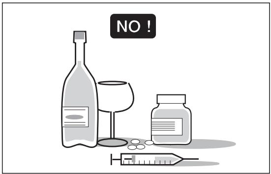
Fig. 2
BASIC SAFETY RULES
To drive the vehicle it is necessary to be in possession of all the requirements prescribed by law (driving licence, minimum age, psychophysical ability, insurance, state taxes, vehicle registration, number plate, etc.).
Gradually get to know the vehicle by driving it first in areas with low traffic and/or private areas.
The use of medicines, alcohol and drugs or psychotropic substances notably increases the risk of accidents.
Be sure that you are in good psychophysical conditions and fit for driving and pay particular attention to physical weariness and drowsiness.
Most road accidents are caused by the driver's lack of experience.
NEVER lend the vehicle to beginners and, in any case, make sure that the driver has all the requirements for driving.
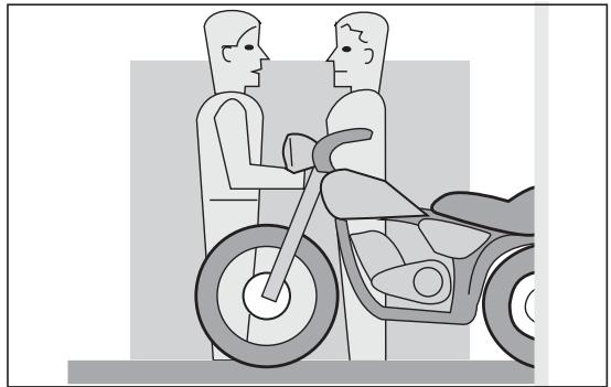
Fig. 3
Rigorously observe all road signs and national and local road regulations.
Avoid abrupt movements that can be dangerous for yourself and other people (for example: rearing up on the back wheel, speeding, etc.), and give due consideration to the road surface, visibility and other driving conditions.
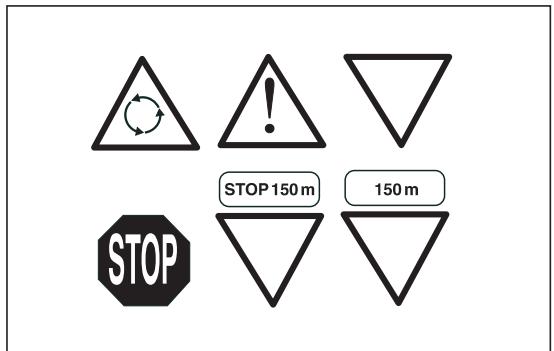
Fig. 4
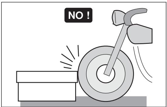
Fig. 5
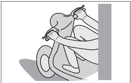
Fig. 6
Avoid obstacles that could damage the vehicle or make you lose control.
Avoid riding in the slipstream created by preceding vehicles in order to increase your speed.
Always drive with both hands on the handlebars and both feet on the footrests (or on the rider's footboards), in the correct driving posture.
Avoid standing up or stretching your limbs while driving.
The driver should pay attention and avoid distractions caused by people, things and movements (never smoke, eat, drink, read, etc.) while driving.
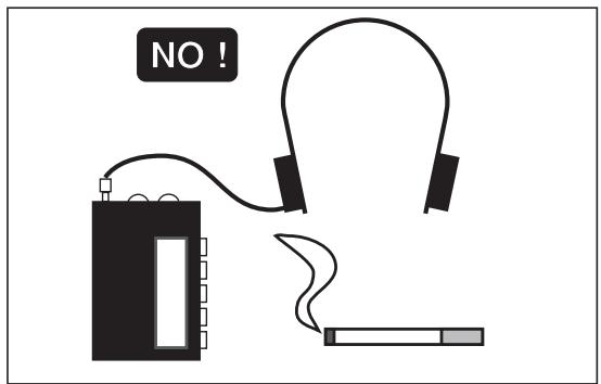
Fig. 7
Use only the vehicle's specific fuels and lubricants indicated in the "LUBRICANT CHART"; check all oil, fuel and coolant levels regularly.
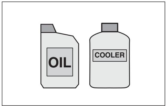
Fig. 8
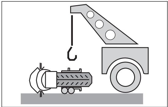
Fig. 9
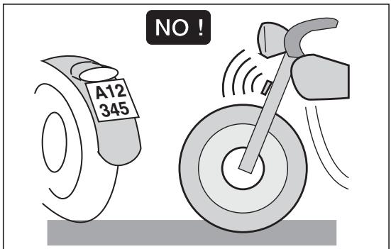
Fig. 10
If the vehicle has been involved in an accident, make sure that no damage has occurred to the control levers, pipes, wires, braking system and vital parts.
If necessary, have the vehicle inspected by an Concessionario Ufficiale aprilia who should carefully check the frame, handlebars, suspensions, safety parts and all the devices that you cannot check by yourself.
Always remember to report any malfunction to the technicians to help them in their work.
Never use the vehicle when the amount of damage it has suffered endangers your safety.
Never change the position, inclination or colour of: number plate, direction indicators, lights and horns.
Any modification of the vehicle will result in the invalidity of the guarantee.
Any modification of the vehicle and/or the removal of original components can compromise vehicle performance levels and safety or even make it illegal.
We recommend respecting all regulations and national and local provisions regarding the equipment of the vehicle.
In particular, avoid all modifications that increase the vehicle's performance levels or alter its original characteristics.
Never race with other vehicles.
Avoid off-road driving.
CLOTHING
Before starting, always wear a correctly fastened crash helmet. Make sure that it is homologated, in good shape, of the right size and that the visor is clean.
Wear protective clothing, preferably in light and/or reflecting colours. In this way you will make yourself more visible to the other drivers, thus notably reducing the risk of being knocked down, and you will be more protected in case of fall.
This clothing should be very tight-fitting and fastened at the wrists and ankles; strings, belts and ties should not be hanging loose; prevent these and other objects from interfering with driving by getting entangled with moving parts or driving mechanisms.
ONLY ORIGINALS
Fig. 11
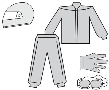
Fig. 12
NO!
Fig. 13
OK?
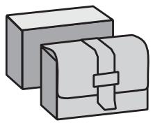
Fig. 14
ACCESSORIES
The owner of the vehicle is responsible for the choice, installation and use of any accessory.
Avoid installing accessories that cover horns or lights or that could impair their functions, limit the suspension stroke and the steering angle, hamper the operation of the controls and reduce the distance from the ground and the angle of inclination in turns.
Avoid using accessories that hamper access to the controls, since this can prolong reaction times during an emergency.
Big fairings and windshields installed on the vehicle may produce aerodynamic forces that affect the stability of the vehicle, especially when riding at high speed.
Make sure that the equipment is well fastened to the vehicle and not dangerous during driving.
Do not install electrical devices and do not modify those already existing to avoid electrical overloads, because the vehicle could suddenly stop or there could be a dangerous current shortage in the horn and in the lights.
aprilia recommends the use of genuine accessories (aprilia genuine accessories).
LOAD
Be careful and moderate when loading your luggage. Keep any luggage loaded as close as possible to the center of gravity of the vehicle and distribute the load uniformly on both sides, in order to reduce umbalance to the minimum. Furthermore, make sure that the load is firmly secured to the vehicle, especially during long trips.
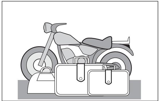
Fig. 15
Avoid hanging bulky, heavy and/or dangerous objects on the handlebars, mudguards and forks, because the vehicle might respond more slowly in turns and its manoeuvrability could be unavoidably impaired.
Do not place bags that are too bulky on the vehicle sides and do not ride with the crash helmet, because they could hit people or obstacles, making you lose control of the vehicle.
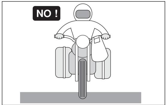
Fig. 16
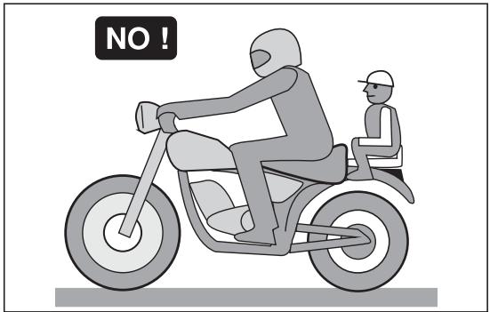
Fig. 17
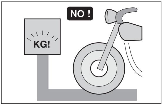
Fig. 18
Do not carry any bag if it is not tightly secured to the vehicle.
Do not carry bags which protrude too much from the luggage-rack or which cover the lights, horn or indicators.
Do not carry animals or children on the glove compartment or on the luggage rack.
Do not exceed the maximum load allowed for each side-bag.
When the vehicle is overloaded, its stability and its manoeuvrability can be compromised.
TYRE INFLATION PRESSURE
| Kind of drive | Driver only | |
| Front | Rear | |
| Off-road | 1,3 bar | 1,4 bar |
| On mixed roads | 1,5 bar | 1,6 bar |
| On asphalt paved roads | 1,6 bar | 1,8 bar |
| Kind of drive | Driver + Passenger (*) | |
| Front | Rear | |
| Off-road | 1,5 bar | 1,6 bar |
| On mixed roads | 1,7 bar | 1,8 bar |
| On asphalt paved roads | 1,8 bar | 2,0 bar |
(*) in the countries where required
Maximum front and rear pressure: 2,5 bar
Low pressure can cause handling problems and the tendency to weave and in extreme cases loss of control.
Moreover this will cause a great increase of rolling friction.
The results are: high consumption of fuel and reduced maximum speed.
The disadvantage may cause a damage of the cover, due to excessive local deformation.

Tyre pressure must be checked when the tyres are at environment temperature, when the vehicle has not been moved in 2 or 3 hours for more than 1km

Check the depth of the tyre tread often, if it is worn below the allowable limit (2 - 3 mm.) change the tyre.
- The tyre should often be inspected for signs of damage or cuts.
- Blowings or irregular wavings are showing internal damages, which request the prompt replacement of the tyre.

Remember: 1 mile = 1.6 km
1 km = 0.625 miles
ARRANGEMENT OF THE CONTROLS
The control devices are positioned as indicated in figures 3 and 4, as follows:
KEY
1) Clutch lever
2) Cold start control
3) Front brake lever
4) Twist grip
5) Rear brake pedal
6) Kick-starter
7) Gear pedal
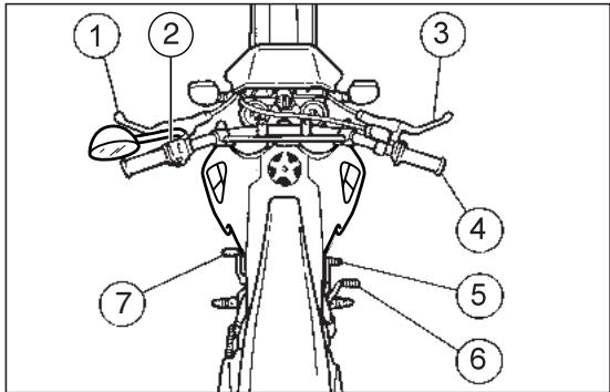
Fig. 19
KEY
1) Cold start lever (▶)
2) Multifunction computer
3) Ignition / steering lock switch (♂ - ♀ - ⌒)
4) Dimmer light switch ( D - D) and high beam signalling push button ( D)
5) Horn push button (1-)
6) High beam warning light (ED)
7) Speedometer/odometer with trip counter
8) Neutral indicator warning light (N)
9) Mixer oil reserve warning light (空)
10) Turn indicator warning light ( )
11) Low beam warning light (D)
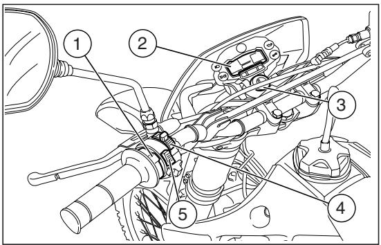
Fig. 20
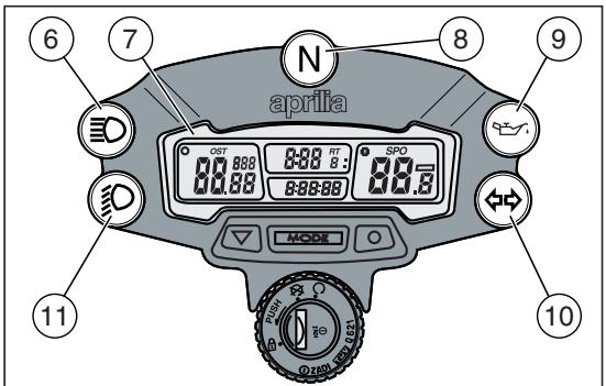
Fig. 21
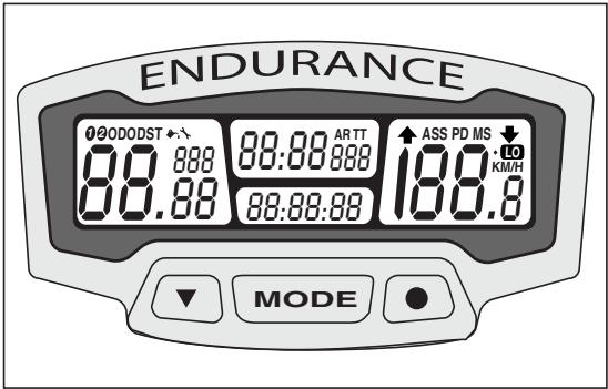
Fig. 22
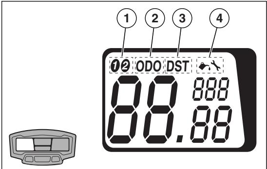
Fig. 23
MULTIFUNCTION COMPUTER
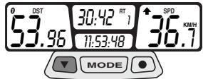
The display is provided with an automatic shutoff function. In case the vehicle or the display are left unused for more than 30 minutes, the display will be automatically disabled. All the pre-set data will nevertheless be stored. The display will be automatically re-enabled as soon as one of the push Buttons is pressed or the vehicle is used again.
KEY
1-2 Vehicle selection
KM/H - MPH Mi or km selection
SPD Current speed
AS Average speed
MS Max.speed
TT Trip meter
RT Partial race time
ART Total race time
00:00:00 Time 12h or 24h
DST Partial distance covered by the vehicle
ODO Total distance covered by the vehicle
Lubrication warning light
Maintenance warning light
Display backlighting
Low battery

By simply setting the front wheel circumference, two different types of vehicles,
bike 1 and bike 2, can be stored inside the multifunction computer memory.
Left display: Vehicle (1), total distance covered (2), partial distance covered (3) and maintenance functions (4) can be selected;
Centre display: total and partial race time (5) and trip meter (6) can be selected;
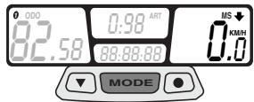
Right display: average (7), max (8) and current (9) speeds and Km/mi (10) functions can be selected.
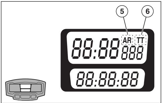
Fig. 24
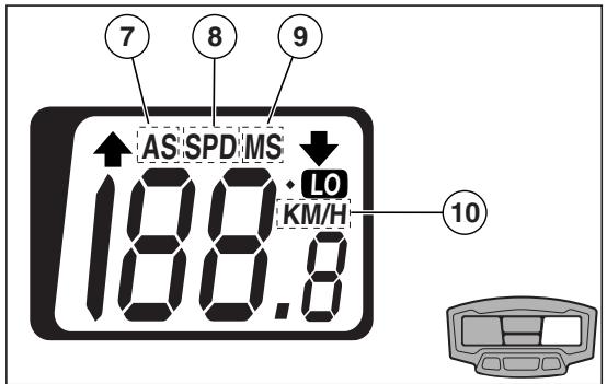
Fig. 25
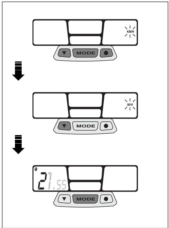
Fig. 26
START-UP SETTING
Metric system setting (KM/H or MPH)
Keep the three push buttons simultaneously pressed for about 2 seconds, then press any of them to start settings.
Press left push button to change the unit of measurement from "km" to "mi" (KM/H to MPH) or vice-versa.
- Keep centre "MODE" push button pressed for about 1.5 seconds to confirm. Then start wheel diameter "WS" setting.

As soon as the MODE push button is pressed, the actual wheel diameter value first flashing datum will appear on the left.
Setting the "WS" wheel diameter
To change the flashing value, press the left push button.
Press right push button to go to next value and then press left push button again to change this value.
Pre-set value 2170.
- Keep centre "MODE" push button pressed for about 1.5 seconds to confirm. Then start time setting.

As soon as the MODE push button is pressed, time actual setting (24h or 12 h)
will appear on the centre display.

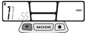

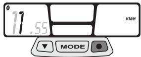

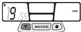
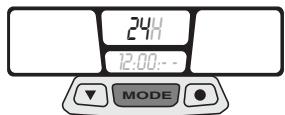
Fig. 27
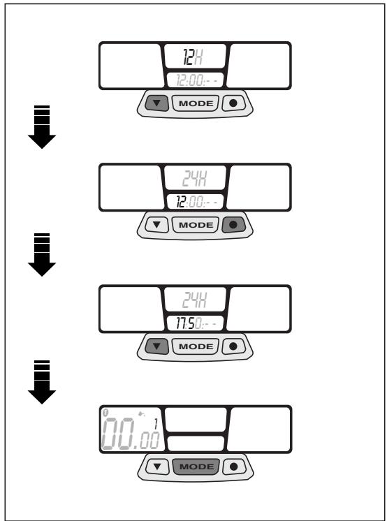
Fig. 28
Time setting
Press left push button to select time displaying (24h or 12 h).
Press right push button to set the "hour". Press left push button to change the value.
Press right push button to set the "minutes". Press left push button again to change the value.
Keep centre "MODE" push button pressed for about 1.5 seconds to confirm. Then start preventative lubrication check.

As soon as the MODE push button is pressed, the lubrication symbo - with the list of preventative services to be made - will stand start flashing on the left display.
Preventative lubrication check

The preventative lubrication check is already pre-set after the first 100km (60 mi) for 1 and after the first 300km (200 mi) for vehi
To change lubrication interval, refer to page 30 (STANDARD SETTING).
Press left push button to modify the value.
Press right push button to shift to next value.
- Keep centre "MODE" push button pressed for about 1.5 seconds to confirm. Then start preventative maintenance check.

If the lubrication check function is not used, set all values to zero.

As soon as the MODE push button is pressed, the maintenance symbol - with a number of preventative services to be made - appear and start flashing on the left display.

Checks to be managed by the user. Do not confuse with scheduled maintenance
services.
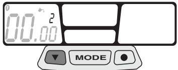

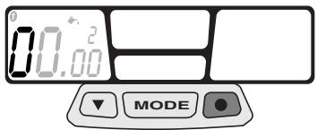

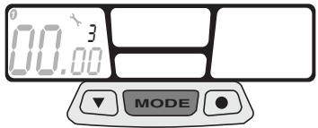
Fig. 29
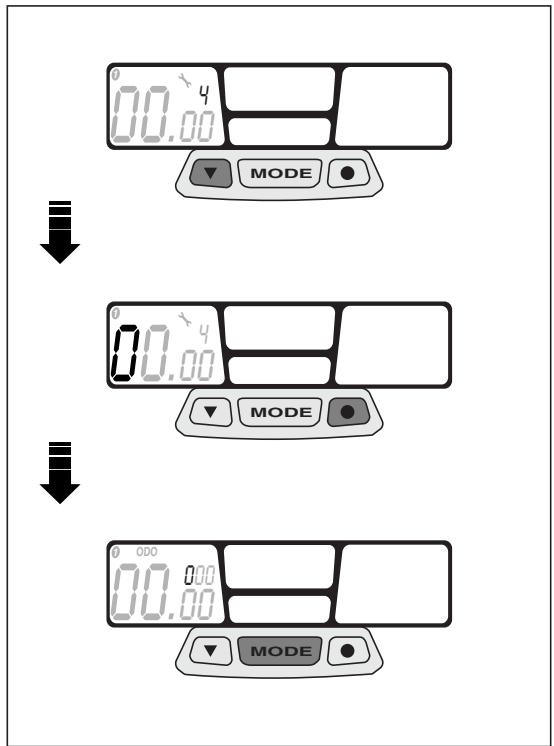
Fig. 30
Preventative maintenance check
The preventative maintenance check is already pre-set after the first 300 km (200 mi) for vehicle 1 and after the first 990 km (600 mi) for vehicle 2.
To change maintenance check interval, refer to page 30 (STANDARD SETTING).
Press left push button to modify the value.
Press right push button to shift to next value.
- Keep centre "MODE" push button pressed for about 1.5 seconds to confirm. Then start total distance setting (ODO).
As soon as the MODE push button is pressed, the ODO wording will appear on the left display.
Checks to be made by the user. Do not confuse with scheduled maintenance services.
Checking the total distance covered (ODO)
Press left push button to modify the value.
Press right push button to shift to next value.
Keep centre "MODE" push button pressed for about 1.5 seconds to confirm. Then start total race time setting (ART).

As soon as the MODE push button is pressed, the ART wording will appear on
the centre display.
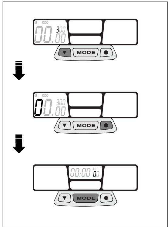
Fig. 31
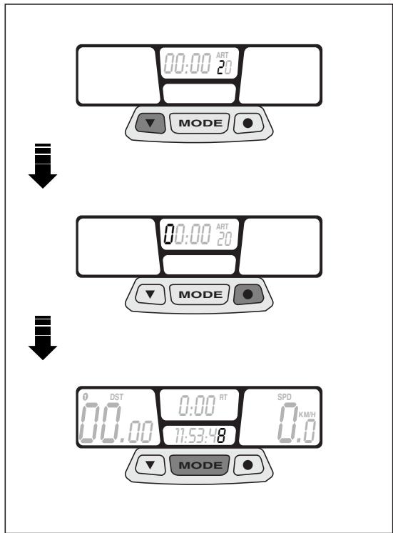
Fig. 32
Checking the total race time (ART)
Press left push button to modify the value.
Press right push button to shift to next value.
- Keep centre "MODE" push button pressed for about 2 seconds to confirm. Start-up setting is now completed.
Programming the second vehicle
Keep the right push button pressed for about 5 seconds. The "WS" wheel diameter value of the second vehicle will appear on the left display. The menu relating to the second vehicle will be automatically enabled after a few seconds.

Keep the two outer push buttons pressed for about 2 seconds to enable the STAN-
DARD SETTING programme relating to the second vehicle (bike 2).
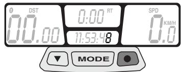


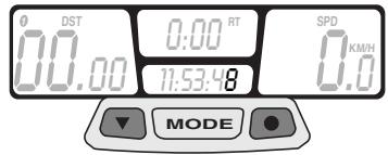
Fig. 33
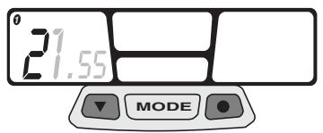
Fig. 34
WS CLOCK ODO ART WS
STANDARD SETTING

- Keep the two outer push buttons pressed for about 2 seconds to enable the STAN-SETTING programme.
This menu will allow you to modify the wheel diameter, the time setting, the vehicle lubrication and maintenance interval, the total distance covered (ODO) and the total race time (ART).
The metric system setting, KM/H to MPH or vice-versa, can be modified only from the START-UP SETTING menu.
PARAMETERS SETTING/DISPLAYING

Press the centre MODE push button to scroll the different setting screens.
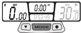
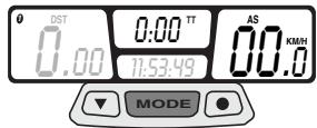
During operation, screen (A) - showing the distance covered after the last resetting (TT), the current speed, time and partial race time (RT) - will be displayed. Press centre push button "MODE" to shift to screen (B) and press it again to shift again to screen (C).

Screens (B and C) will be displayed for 5 seconds only, then screen (A) will appear
again.
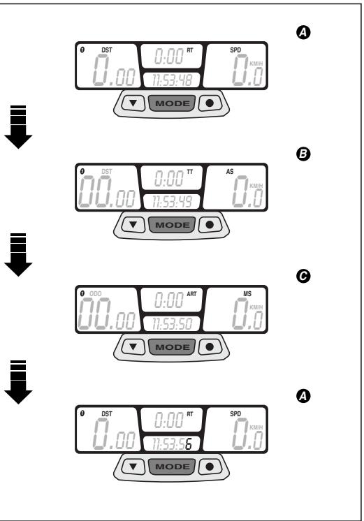
Fig. 35
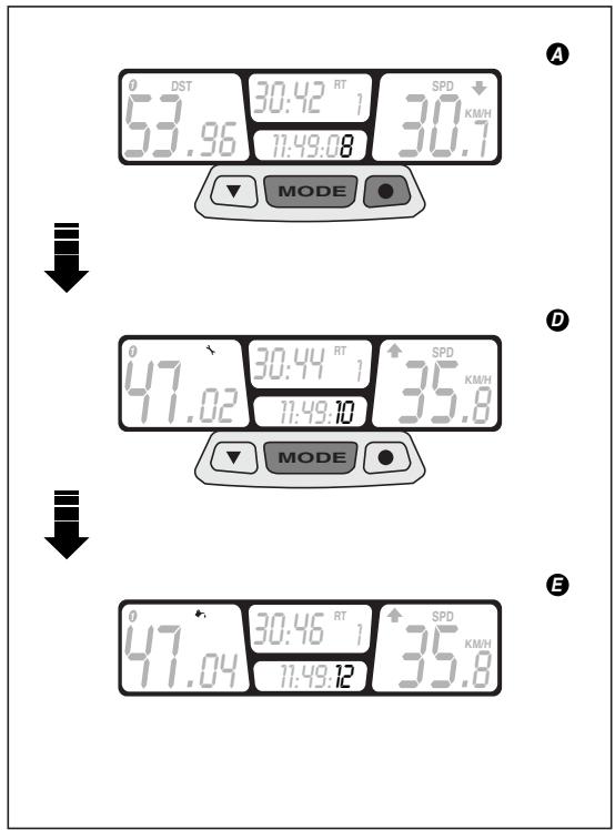
Fig. 36
Keep centre push button "MODE" and right push button simultaneously pressed for about 2 seconds to shift to screen (D) - showing the preventative maintenance check function - and press them again to shift again to screen (E) showing the preventative lubrication check function.
Screens (D and E) will be displayed for 5 seconds only. If no other button is pressed, screen (A) will be displayed again.
DISABLING THE SCHEDULED MAINTENANCE SERVICES
Whenever the scheduled maintenance or lubrication service intervals are not respected, the relating value will start flashing on the left display.
To switch this value off, keep the right and left push button simultaneously pressed for about 2 seconds.
Keep centre push button "MODE" pressed for about 1.5 seconds to go to the wheel diameter screen.
Keep centre push button "MODE" pressed again for about 1.5 seconds to go to the time setting screen and to start setting the preventative lubrication check.
Press left push button to modify the value.
Press right push button to confirm this value and to shift to next value.
Keep centre "MODE" push button pressed for about 1.5 seconds to confirm preventative lubrication values and to shift to next operation. Press left push button to modify the value.
Press right push button to confirm this value and to shift to next value.
Keep right push button pressed again until, after about 2 seconds, the starting screen (A) will appear again..
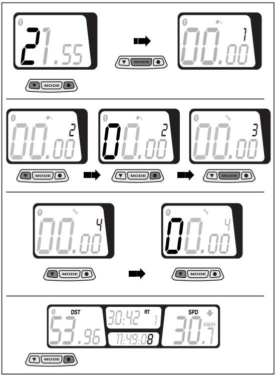
Fig. 37
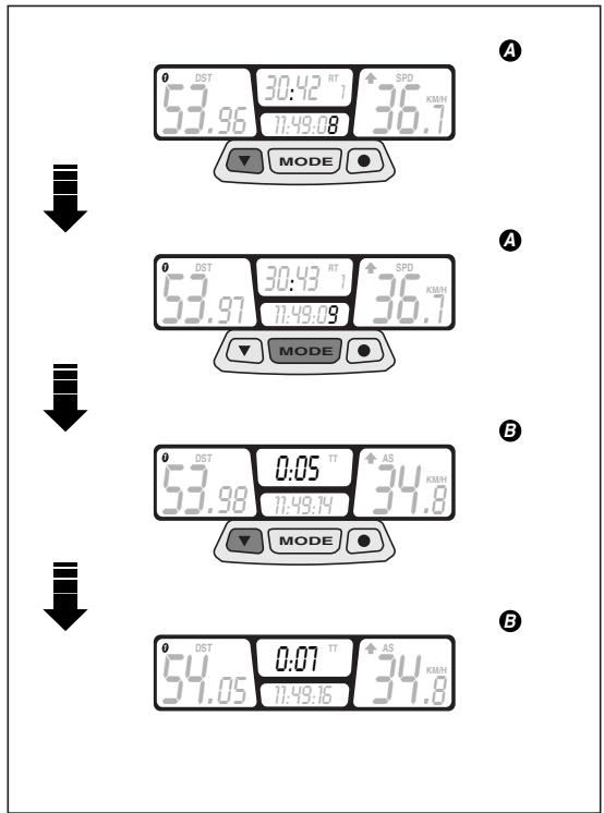
Fig. 38
CHRONOMETER
The multifunction computer is equipped with a chronometer, to be displayed on screen (B) together with trip meter (TT).
Press left push button to enable chronometer.
Press centre push button "MODE" to display screen (B).
Press left push button again to terminate the chronometer function.
RESETTING THE PARTIAL VALUES
This function is used to reset the partial values stored inside the computer memory. In particular:
- Partial distance covered (DST)
- Trip meter (TT)
-
Partial race time (RT)
Maximum speed (MS)
Average speed (AS) -
Keep the left and the centre “MODE” push buttons simultaneously pressed for about 2 seconds. Screen (A) with the reset values will be displayed.
Press centre push button "MODE" to shift to screen (B) and reset the values.
Press centre push button "MODE" again to shift to screen (C) and reset the values.

again.
Screens (B and C) will be displayed for 5 seconds only, then screen (A) will appear


A
B
Fig. 39
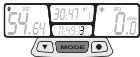
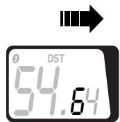


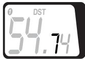

Fig. 40
ALIGNING THE PARTIAL VALUES (TRIP)
The partial distance covered (DST) can be modified by increasing or decreasing the value appearing on the display. This function can be used during competitions to make the displayed value match the one relating to the racetrack.

Do not use this function to reset the value (DST); to reset partial values refer to page
35 (RESETTING THE PARTIAL VALUES).
Keep the centre "MODE" push button pressed for about 3 seconds.
Press the right push button to increase the value.
Press the left push button to decrease the value.
Screen (A), with the changes made, will be displayed after about 3 seconds.
BACKLIGHTING
Press right push button to enable display backlighting, The light will be automatically switched off after 4 seconds.
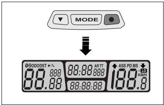
Fig. 41
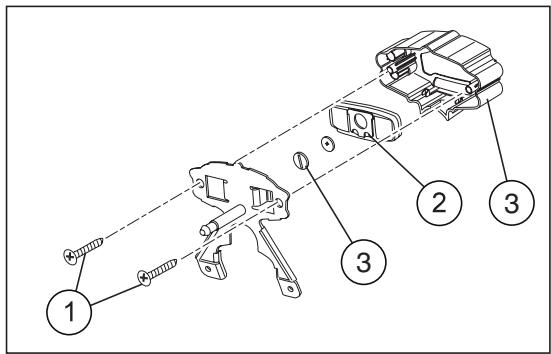
Fig. 42
CHANGING THE BATTERY
Remove headlight fairing.
Loosen the 2 cross-head screws between instrument holder and metal plate.
Disconnect the 2-way connector from speedometer transmission unit.
To remove the digital instrument from its holder, slightly press on LCD side.
Disconnect the "sliding shoe" from the digital instrument body.
Loosen the battery cover cap behind the digital instrument.
Change the "CR2032" battery.
IGNITION SWITCH / STEERING LOCK / LIGHT SWITCH
The ignition switch can be turned to three positions:
First click clockwise = "O" (start)
Central position = " 哭 (stop)
Anticlockwise rotation = 空^ (steering lock)
| Position | Function | Key removal |
| Steering lock | The steering is locked. It is neither possible to start the engine, nor to switch on the lights. | It is possible to remove the key. |
| × | Neither the engine, nor the lights can be switched on. | It is possible to remove the key. |
| ○ | The engine can be start. Low beams will be automatically switched on | It isn't possible to remove the key. |
STEERING LOCK

Never turn the key to the "B" position while driving, in order to avoid losing control of the vehicle.
OPERATION
To lock the steering turn the handlebars completely to the left.
With the key on the "position, press the key, release it and turn it to the " position.
Remove the key.
CRASH-HELMET LOCK (Fig. 43)
Using the ignition key it is possible to have access to the crash-helmet lock positioned on the rear part of the vehicle.
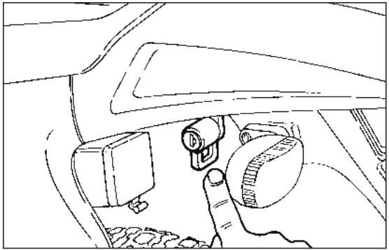
Fig. 43
GLOVE / TOOL COMPARTMENT (Fig. 44)
It is positioned on the inner part of the left side of the fairing.
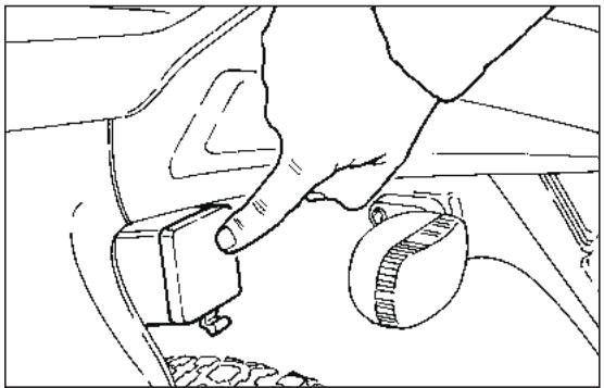
Fig. 44
INSTRUCTIONS FOR USE
Do not use any "brake lock" devices. Failure to heed this warning can seriously damage the braking system and lead to an accident thus provoking serious injuries or death.
Before starting the vehicle for the first time, check that the tyres are inflated to the correct pressure (see "TYRE INFLATION PRESSURE") and fill the fuel tank with premium grade petrol (see "TECHNICAL DATA").
Fill the mixer oil tank with oil (see "LUBRICANT CHART").

The motor must not be filled with petrol/ oil mixed at filling stations.
- Check the engine coolant level (see "COOLANT CHECKING").
Make sure that there are no air bubbles in the mixer oil pipe (from the oil tank to the pump); if necessary, bleed the pump by means of the appropriate screw (see "SEPARATE LUBRICATION").
RUNNING
In the initial period of use is very important for the future performance of the engine.
We advise warming up the engine before starting off, allowing it to turn over for a few minutes at a low speed.
If possible, drive on hill roads and/or roads with many bends, so that the engine, the suspensions and the brakes undergo a more effective running-in.
After the first month of use, let the 1^st servicing coupon be made by an aprilia Official Dealer.

If there is no oil left in the mixer oil tank, avoid using the vehicle so as not to cause irreparable damage to the motor.
Then bleed the system (see "SEPARATE LUBRIFICATION") after filling the tank with specific oil (see "LUBRICANT CHART).
The disc and shoes of the front brake require a running-in period (about 500km ) before reaching optimum performance conditions.

Remember: 1 mile = 1.6 km
1km = 0.625 miles.
PRELIMINARY CHECKING OPERATIONS
| Component | Check | Page |
| Front and rear disc brakes | Check the functioning, the idle stroke of the control levers, the fluid level and make sure there are no leaks. Check the wear of the pads. If necessary, top up the fluid tank. | 54-55 56-57 |
| Accelerator | Make sure that it works smoothly and that it is possible to open and close it completely, in all steering positions. If necessary, adjust and/or lubricate it. | 67 |
| 2 stroke oil/ transmission oil | Check and/or top up if necessary. | 50-52 |
| Wheel/tyres | Check the tyre surface, the inflation pressure, wear and tear and any damage. | 17 |
| Brake levers | Make sure that they work smoothly. If necessary, lubricate the articulations and adjust the stroke. | 54 |
| Clutch | The idle stroke at the end of the clutch lever must be about 10 mm; the clutch must operate without jerking and/or slipping. | 51 |
| Steering | Make sure that the steering rotates smoothly, without any clearance or slackening. | — |
| Side stand and center stand | Make sure that it works smoothly and that the spring tension brings it back to its normal position. If necessary, lubricate joints and hinges. | — |
| Fastening elements | Make sure that the fastening elements are not loose. If necessary, adjust or tighten them. | — |
| Drive chain | Check the slack. | 59-60 |
| Fuel tank | Check the fuel level and top up, if necessary. Make sure there are no leaks or air bubbles in the circuit. | — |
| Coolant | Check level | 62÷64 |
| Lights, warning lights, horn and electric devices | Check the proper functioning of the acoustic and visual devices. Change the bulbs or intervene in case of failure. | 71÷73 |
STARTING (Fig. 45)
Open the fuel coock on the tank (Fig. 45).
Insert the ignition key and turn to "O" position.
In case of cold start refer to page 44 (COLD START), switch the cold start control on.
Place gears in neutral position, (neutral indicator warning light "N" comes on) or pull on clutch lever.
Act on the kick starter with your right foot, releasing it immediately.

If the mixer oil reserve warning light "..." comes on during the normal running of the engine, this means that the mixer oil
reserve is being used; in this case, provide for topping up.

Do not continue to press the kickstart lever or attempt to use it while the engine is running.
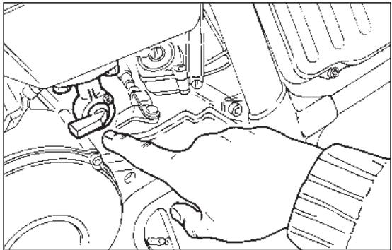
Fig. 45
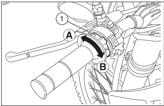
Fig. 46
COLD START
Pull front brake lever to keep the front wheel locked.
Turn gear control lever to neutral position (green warning light "N" on).
In case of cold start, rotate the cold start lever "|\n" (1) upwards (Pos. A).
Rotate start pedal outwards.

Do not operate the start pedal once engine has been fired
Strongly push the start pedal, then release it immediately. If necessary, repeat this operation until engine is started.
Keep front brake lever pulled and do not open throttles until departure.
Do not accelerate abruptly with the engine cold. To minimise pollutants emission and fuel consumption, warm up engine by driving at a low speed for the first kilometres.
Once the engine is warm, turn cold star lever "|\n" (1) downwards (Pos. B).
- Once the vehicle has started, wait for a few seconds and then switch the cold start control off.
When the engine is warm it should be started without using the choke.
The engine must not remain turned on with the battery or the voltage regulator disconnected; this would cause irreparable damage to the electrical system.
MOVING OFF (Fig. 47)
After warming up the engine:
Pull in the clutch lever.
Engage 1st gear (gear pedal downwards). The neutral indicator warning light "N" go out.
Then gradually release the clutch and turn the throttle at the same time.
CHANGING GEAR (Fig. 47)
Release the throttle, pull the clutch lever in and lift the gear lever upwards to change to the higher gears.
Vice versa, push downwards when changing to a lower gear.

Before riding the motor cycle we advise you to get to know the controls and all their functions as explained in this manu
al. Contact your aprilia Official Dealer if there is anything you do not understand.
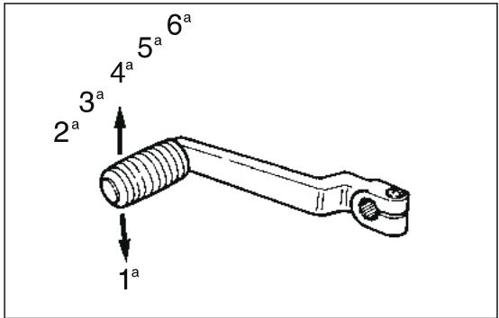
Fig. 47
STOPPING THE ENGINE
Release the twist grip, set the gear in neutral position, neutral indicator warning light "N" comes on, and turn the ignition key in an "O" position. Turn off the fuel cock.

If there should be an excessive coolant temperature during normal operation, turn off the engine.
Wait for it to cool down, then check the level of the coolant (see "COOLANT CHECKING") and top up if necessary.
If the level not is normal have the cooling system checked by an aprilia Official Dealer.

The vehicle is equipped with a side stand with automatic return. To prevent damages to the person and to the vehicle, put
the vehicle on its stand only after having switched off the engine and having got off from the vehicle I.h. side.
Open the side stand making sure it has run its entire stroke; only then you may charge it with the vehicle load.

It is absolutely forbidden to put the vehicle on the stand while being seated on it.
MAINTENANCE
See "PERIODIC MAINTENANCE CHART".
Before beginning any maintenance operation or any inspection of the vehicle, stop the engine, extract the key, wait until the engine and the exhaust system have cooled down and if possible lift up the vehicle by means of the proper equipment, on firm and flat ground. Keep away from the red-hot parts of the engine and of the exhaust system, in order to avoid burns. Do not hold any mechanical piece or other parts of the vehicle with your mouth: the components are not edible and some of them are noxious or even toxic.

If not expressly indicated otherwise, for the reassembly of the units repeat the disassembly operations in reverse order.
Usually ordinary maintenance operations can be carried out by the user, but sometimes a basic knowledge of mechanics and specific tools are required. If you need assistance or technical advice consult your aprilia Official Dealer, who can ensure you quick and careful servicing.
REGULAR SERVICE INTERVALS CHART
OPERATIONS TO BE CARRIED OUT BY THE aprilia Official Dealer (WHICH CAN BE CARRIED OUT EVEN BY THE USER).
Key
① = check and clean, adjust, lubricate or change, if necessary;
② = clean;
③ = change;
④ = adjust.
= to be always made in case of off-road use.

Carry out the maintenance operations
more frequently if you use the vehicle in rainy and dusty areas or on uneven ground.
| Component | End of running-in period (after 1 month) | Every 12 months | Every 24 months |
| Battery - Terminal fastening - Electrolyte level | ① | ① | - |
| Spark plug | ② | every 3 months: ② every 6 months: ③ | |
| Air cleaner * | ① | ② | - |
| Clutch clearance | ④ | ④ | - |
| Light system | ① | ① | - |
| Brake fluid | - | ① | - |
| Coolant | every 3 months: ① | ||
| Mixer oil level | check before every use | ||
| Transmission oil | ③ | ① | ③ |
| Headlight beam direction - operation | - | ① | - |
| Engine idling rpm | ④ | ① | - |
| Wheels/tyres and inflation pressure | every month: ① | ||
| Drive chain tension and lubrication * | every month: ① | ||
| Front and rear brake pad wear * | ① | every month: ① | |
OPERATIONS TO BE CARRIED OUT BY THE aprilia Of-ficial Dealer.
Key
① = check and clean, adjust, lubricate or change, if necessary;
② = clean;
③ = change;
④ = adjust.
= to be always made in case of off-road use.
Carry out the maintenance operations more frequently if you use the vehicle in rainy and dusty areas or on uneven ground.
| Component | End of running-in period(after 1 month) | Every 12 months | Every 24 months |
| Rear shock absorber | - | - | ① |
| Carburettor | - | - | ② |
| Transmission cables and controls | ① | ① | - |
| Wheel centering | - | ① | - |
| Steering tube bearings and steering slack | ① | ① | - |
| Wheel bearings * | - | ① | - |
| Brake discs | ① | ① | - |
| Mixer oil filter | - | - | ② |
| General running of the vehicle | ① | ① | - |
| Braking systems | ① | ① | - |
| Cooling system | ① | ① | - |
| Brake fluid | every year: ③ | ||
| Coolant | every 2 years: ③ | ||
| Exhaust silencer/exhaust terminal | - | ② | - |
| Fork oil and oil seal | every 2 years: ③ | ||
| Piston and piston rings | every 2 years: ①every 4 years: ③ | ||
| Wheels/tyres and inflation pressure | ① | ① | - |
| Fastening battery terminals | ① | ① | - |
| Nut, bolt, screw tightening | ① | ① | - |
| 2 stroke oil reserve warning light | ① | ① | - |
| Spokes tension. | ① | ① | - |
| Final transmission (chain, crown, pinion) | - | ① | - |
| Fuel pipe | - | ① | every 4 years: ③ |
| Mixer oil pipes | - | ① | every 4 years: ③ |
| Clutch wear | - | ① | - |
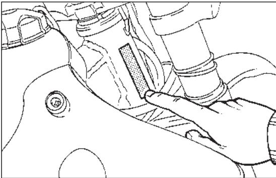
Fig. 48
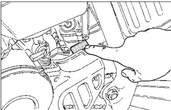
Fig. 49
IDENTIFICATION DATA
It is a good rule to write down the frame and engine numbers in the space provided in this manual.
The frame number can be used for the purchase of spare parts.

Do not alter the identification numbers if you do not want to incur severe penal and strative sanctions. In particular, the alterthe frame number results in the immediatety of the guarantee.
FRAME NUMBER (Fig. 48)
The frame number is stamped on the left side of the steering head.
Frame n°
ENGINE NUMBER (Fig. 49)
The engine number is printed in the space provided upper the pinion.
Engine n°
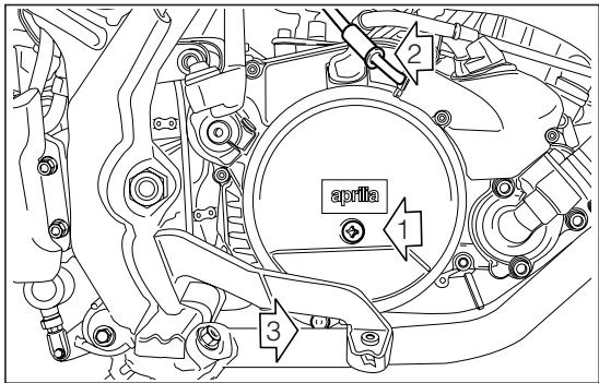
Fig. 50

In case of oil leakages or malfunctions, contact your aprilia Official Dealer.
DO NOT DISPOSE OF OIL IN THE ENVIRONMENT.
CHECKING THE GEAR OIL LEVEL (Fig. 50)
Hold the vehicle in an upright position with respect to the ground.
Remove the checking screw (1) (right side cover): the oil level is correct if it reaches the bottom edge of the hole when the vehicle in an upright position.
If necessary, top up through the filler hole (2).
GEAR OIL REPLACEMENT (Fig. 50)
This operation should be carried out while the engine is warm so that the oil drains off faster.
The procedure is as follows.
Unscrew the filler plug (2).
Place a suitably large container (min. 1000~cm^3 ) under the engine to catch the old oil.
Unscrew the drain plug (3) placed on the bottom.
- Once all the oil has drained off, replace the drain plug (3) and pour 820~cm^3 of oil into the filler hole (2) (see "LUBRICANT CHART").
CLUTCH ADJUSTMENT (Fig. 51-52)
This model is equipped with two devices for adjusting the length of the clutch cable.
Check the correct adjustment of the clutch cable from time to time, ensuring that the idle stroke of the control lever is from 3 ÷ 4 ~mm (Fig. 51).
If this distance is not correct, turn the control lever adjuster (1) or the adjuster on the motor cover (Fig. 52).

If it is not possible to adjust the clutch by means of the adjusters, contact your aprilia Official Dealer
The clutch must be adjusted when it does not "release" correctly and the vehicle tends to move even with the clutch pulled.
On the contrary, if the clutch "slips" the acceleration of the vehicle will not be in proportion to the acceleration of the motor.
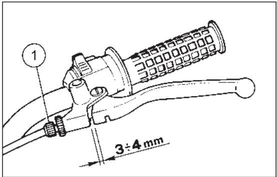
Fig. 51
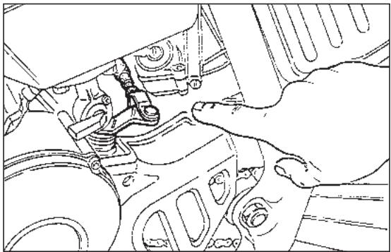
Fig. 52

Fig. 53
SEPARATE LUBRICATION (Fig. 53-56)
Top up the mixer oil tank every 500~km
The vehicle has a separate lubrication system which includes an mixer oil tank (Fig. 53) (1,3 with a reserve of 0,5) and a variable-capacity oil supply pump (the capacity varies according to the number of revs of the motor and the opening of the throttle) (Fig. 53).
When the oil reaches reserve level, this is indicated by the coming on of the mixer oil reserve warning light "
The capacity is predetermined in the design phase, so there is no need for the user to make any adjustment. It is necessary to bleed air from the pump whenever it has to be dismantled, the mixer oil supply pipe is detached, or when the lubricant in the mixer oil tank is completely exhausted.
Proceed as follows:
Empty the fuel tank and fill it with 2 ÷ 3 of mixture containing 1 % oil (see “LUBRICANT CHART”).
Start the motor and let it idle.
Unscrew the drainage screw (1) and at the same time completely rotate the pump control lever (2) until the oil drains off, then tighten the screw again.
Keep the pump lever rotated until all traces of air bubbles have completely disappeared from the carburettor supply pipe.

For greater safety we advise using up all the blended fuel in the tank before refilling with only premium grade petrol (see
"TECHNICAL FEATURES").
Adjust the motor idling speed, then check that the end play of the oil pump and the carburettor cables is the same; if not, regulate the adjusters provided in order to obtain a clearance of 1mm .
Check that there are no twist in the petrol hose and oil hose. If there are twist then replace the hose.
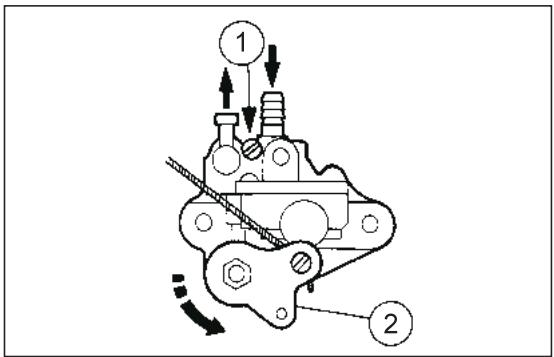
Fig. 54
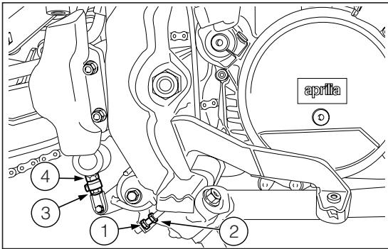
Fig. 55
ADJUSTING THE REAR BRAKE (Fig. 55)
The brake pedal is positioned ergonomically during the assembly phase.
If necessary, it is possible to adjust the height of the brake pedal:
Screw the lock nut (3) on the pump control rod (4) completely.
Screw the pump control rod completely (4).
Loosen check nut (1).
Screw or loosen adjuster (2) until the pedal is at the desired height.
Lock the brake adjuster (2) by means of the lock nut (1).
Unscrew the pump control rod (4) and restore the clearance between the brake adjuster and the stroke point.
Make sure that some clearance is present between brake rod and master cylinder. This will avoid brake to be left unintentionally operated with a consequent early wear of braking system parts.
Brake rod and master cylinder clearance shall be: 0.5 ÷ 1 ~mm .
Lock the pump control rod by means of the lock nut (3).

Check the braking efficiency. If necessary, contact your aprilia Official Dealer.
CHECKING AND BLEEDING THE FRONT AND REAR BRAKE (Fig. 56)
The vehicle is provided with a hydraulically controlled front and rear disc brake. The brake fluid level in the pump tank must be checked from time to time.
After the first 500~km or whenever an excessive idle stroke of the lever is found, the hydraulic system must be bled to remove any air bubbles that may have formed.

The bleeding operations for the front and rear braking system are the same.
Remove the protection cap of the caliper breather valve (1).
Fit one end of a transparent PVC tube (2) over the end of the caliper breather valve.
The other end of the tube must be placed in a receptacle to catch the fluid (3).
Remove the lid of the brake fluid pump and check that the level is correct. If necessary, top up (see "LUBRICANT CHART").
Pull the brake lever slowly and completely (2-3 times). Keeping the lever in pulled position, open the breather valve (1) until fluid and any air bubbles can be seen coming out of the tube.
Close the valve again and release the brake lever.
Repeat the operation described above until no more air bubbles can be seen in the fluid coming out of the valve.
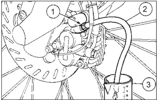
Fig. 56
- Tighten the valve and remove the tube, being careful not to get fluid on the brake pads or the disc.
Reposition the protection cap, top up the reservoir to maximum level and close it carefully.

After reassembly, pull the front brake lever repeatedly and check the proper functioning of the braking system.
Brake fluid is corrosive and can cause damage.

Remember: 1 mile = 1.6 km
1 km = 0.625 miles
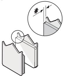
米 = 1.5 ~mm
Fig. 57
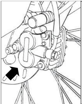
Check brake pads for wear every 2,000 km. In case of off-road use, with mud or sand, check brake pads after every ride.
The pads present a groove that must always be visible.

The following information refers to a single braking system, but are valid for
Disc brake pads wear depends on use, riding style and road surface.

Check brake pads for wear, especially before every trip. To carry out a rapid check on brake pads, proceed as follows:
Raise vehicle on stand.

Front brake caliper is provided with two brake pads. Rear brake caliper is provideto brake pads.
Carry out a visual check between the disc and the pads, proceeding:
From below to above in the "wheel shaft / caliper" direction for front brake calipers;
From above, on the rear part, for rear brake caliper.
The excessive wear of the friction material would cause the contact of the pad metal support with the disc, with consequent metallic noise and production of sparks from the caliper; braking efficiency, safety and soundness of the disc would thus be negatively affected.
If this groove is not visible any more (thickness of the friction surface = 1,5 mm), change the pads.
- For the front brake caliper have both pads changed.
- For the rear brake caliper, have both pads of the caliper changed.
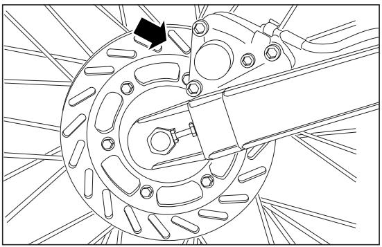
Fig. 58
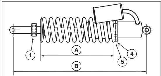
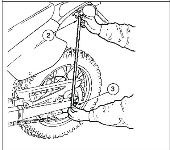
Fig. 59
ADJUSTING THE REAR SUSPENSION (Fig. 59)
The rear suspension comprises a single springshock absorber unit and a lever unit with A.P.S.
The standard rear suspension is suitable for a driver weighing about 75kg
In case your weight or riding style are different from the standard setting, change shock absorber spring length by turning ring nut (4) and (5) or rebound adjuster by turning knob (1).
Rebound adjuster standard setting: 8 ± 1 clicks from the fully closed position.
To check this position:
With the vehicle in an upright position, without the rider and prop stand, measure the distance (2-3).
With the rider sitting in the riding position (feet on the footpegs) and the vehicle in vertical position, measure the distance (2-3) again.
The difference between the two measures (shock absorber pre-loading) must be included between a maximum of 100~mm and a minimum of 90 mm.
To adjust spring (A) pre-load, loosen check ring nut (4) and adjust ring nut (5).
Standard setting: 212mm
Max.pre-load setting: 207mm
CHAIN ADJUSTMENT (Fig. 60)
Stand the vehicle in an upright position and completely extend the rear suspension.
Check that the vertical movement in the lower part of the chain, at a point mid-way between the pinion and the crown, is about 30 - 35 ~mm .
If this distance is not correct, proceed as follows:
Loosen the rear wheel pin fastening nut.

For the wheel centering:
Make sure that on both sides the fixed reference on the rear fork corresponds
to the number indicated on the chain tightener.
Act on the apposite chain tighteners.
- Once the operation has been performed, tighten the rear wheel pin fastening nut.
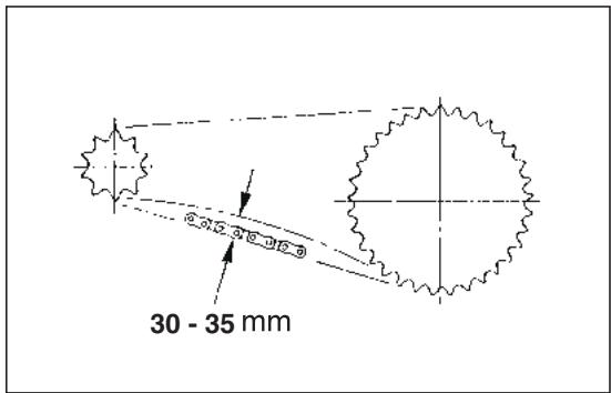
Fig. 60
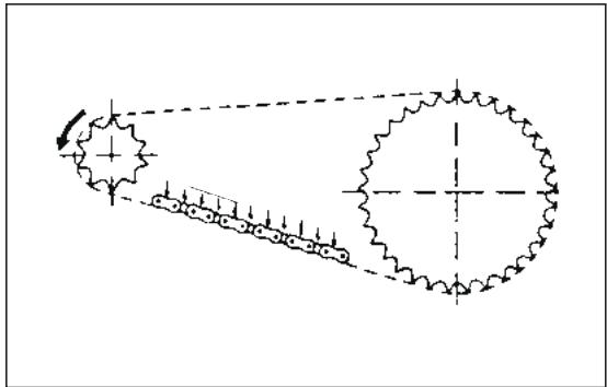
Fig. 61
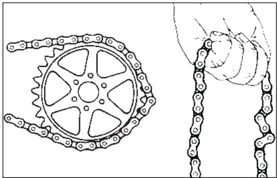
Fig. 62
CHAIN LUBRICATION (Fig. 61)
Proceed to chain lubrication frequently (see "LUBRICANT CHART"), every 4,000 km, every time the vehicle is used off-road on mud or sand.
CHAIN CHECKING (Fig. 62)
From time to time check the wear condition of the chain; make sure that it is not too loose and that there are no angles or seized links. If any faults are found, change the chain.
Never fit a new drive chain on a sprocket wheel/ crown gear with very worn teeth; vice versa do not use a worn chain on a new sprocket wheel/crown gear.
AIR FILTER REMOVIDING AND CLEANING (Fig. 63)
The correctly performed dismantling and cleaning of the air filter is of fundamental importance for good engine performance.
Every 4000km or according to conditions of use, clean the filtering element as follows:
Unscrew and remove the saddle locking nut positioned under the mudguard.
Remove the saddle by lifting it.
Remove the left side of the fairing.
Unscrew and remove the screws of the filter case cover.
Remove the filter case cover (1).
Remove the filtering element.
Wash the filtering element with clean, not-inflammable solvents or solvents with high volatility point, then let it dry thoroughly.
Apply a filter oil or a thick oil (SAE 80W-90) on the whole surface of the filtering element, then squeeze it to eliminate the oil in excess.

The filter must be well impregnated, though not dripping
Reassemble performing all the operations in reverse order, being careful to close the filter box cover correctly.
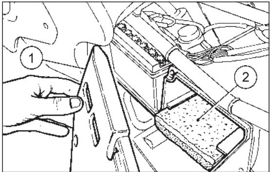
Fig. 63

Remember: 1 mile = 1.6 km
1 km = 0.625 miles
COOLANT CHECKING

Do not use the vehicle if the coolant is below the minimum allowed level.
Do not remove the radiator plug when the engine is hot, since the coolant is under pressure and its temperature is high. If it gets in contact with the skin or with clothes it can cause severe burns and/or damages.
The coolant is noxious:
DO NOT SWALLOW IT.
KEEP AWAY FROM CHILDREN.
Every 2000 km or after using the vehicle in difficult conditions, check the coolant level with cold engine; change the coolant every two years.
The coolant level must be included between 1/4th and 3/4ths of the expansion tank capacity.
If necessary, provide for topping up.
The standard coolant makes it possible to expose the vehicle to temperatures down to -17^ .
CHECKING AND TOPPING UP (Fig. 64)
Let the engine cool down for a few minutes.
Keep the vehicle in vertical position.
Make sure that the level of the fluid contained in the expansion tank (see figure) is included between 1/4th and 3/4ths of the capacity of the expansion tank itself.
If not, remove the filling plug (see figure).

Be careful not to confuse the oil mixer tank with the expansion tank.
- Top up until the fluid level reaches about 3/4ths of the expansion tank.

Do not exceed this level, otherwise the fluid will overflow when the engine is running.
Put back the plug on the expansion tank.

If it is necessary to top up the coolant too frequently, contact your aprilia Official Dealer for a check.
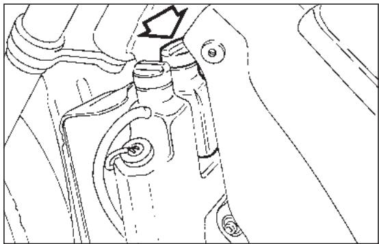
Fig. 64
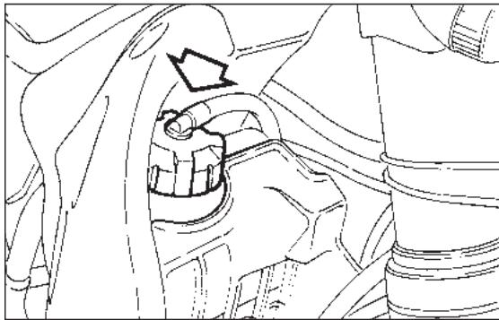
Fig. 65
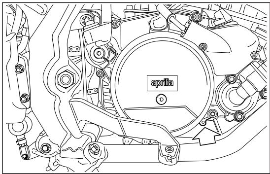
Fig. 66
CHANGING THE COOLANT (Fig. 65-66)
To change the coolant (every 2 years):
Remove the radiator filling plug (Fig. 65).
Remove the expansion tank plug.
- Put a container, with at least 1,5 capacity, under the drain screw (Fig. 66).
- Unscrew the drain screw, thus draining the circuit completely.
- Disconnect the small pipe that joins the expansion tank to the radiator and drain the expansion tank completely.
Screw and tighten the drain screw.
Connect the small pipe.
- Top up the system with 0,9% of fluid (see "LUBRICANT CHART") through the radiator filler.
- Check the level in the expansion tank (between 1/4th and 3/4ths of the capacity of the expansion tank itself); top up if necessary.

Be careful not to confuse the oil mixer tank with the expansion tank.
SPARK PLUG MAINTENANCE
(Fig. 67)
From time to time remove the spark plug with the wrench provided and eliminate the deposits from the space between the porcelain insulator of the central electrode and the body of the plug.
Use a feeler gauge to check that the distance between the electrodes is 0.6 - 0.7mm (see figure).
If the distance is incorrect, bend the side electrode towards the centre one.
Never attempt to bend the centre electrode, to avoid possible damage to the porcelain insulation.

Use only the correct type of spark plug; spark plugs with the wrong heat rating may cause faulty operation.
Recommended spark plug: NGK BR9 ES.
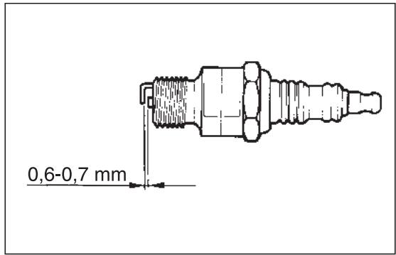
Fig. 67
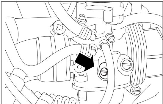
Fig. 68
REGOLAZIONE DEL MINIMO (Fig. 68)
Adjust the idling every time it is irregular.
To carry out this operation, proceed as follows:
Warm the engine up until it reaches the normal running temperature.
Set the gear in neutral position (neutral indicator warning light "N" comes on).
Position the vehicle on the stand.
Connect an electronic revolution counter to the spark plug cable.
Act on the adjusting screw positioned on the carburettor.
By SCREWING IT (rotating it clockwise), you increase the engine rpm.
By UNSCREWING IT (rotating it anticlockwise), you decrease the engine rpm.
The minimum speed of the engine (idling) must be about 1500 rpm.
By twisting the throttle, accelerate and decelerate a few times to verify the correct functioning and to check if the idling speed is constant.

If necessary, contact your aprilia Official Dealer.
ADJUSTING
THE ACCELERATOR CONTROL (Fig. 69)
The slack of the accelerator control must be about 2-3 mm, measured on the the twist grip.
To adjust the slack, proceed as follows:
Remove the protection element (1).
Release the nut (2).
Act on the adjuster (3) placed at the beginning of the accelerator control cable.
- Once you have carried out the adjustment, lock the nut (2) and put back the protection cover (1).
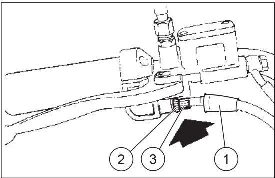
Fig. 69
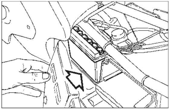
Fig. 70
ELECTRICAL SYSTEM

For battery efficiency (Fig. 70) it is very important that the correct load of acid be observed and that maintenance be car
ried out properly. If the following instructions are scrupulously observed, the battery life will be considerably prolonged.
Preparing the vehicle for the road, charging the battery:
- It is important to let the battery sit for at least 3 - 4 hours after filling it with the solution of sulphuric acid and distilled water, to allow the chemical reaction to be completed.
Then, before 24 hours are up, battery charging should be completed by subjecting it to a current of around 10 to 20% of the rated capacity (for 5 Ah batteries, current 0.5 ÷ 1 A max.).
If this period is not respected, a sulphation reaction begins in the plates which considerably shortens their lives.

The liquid in the battery is toxic and therefore dangerous. Avoid contact with the skin, eyes and clothes.
In the event of contact of the electrolytic solution with the skin or eyes, rinse abundantly with cold water and consult a doctor.
BATTERY MAINTENANCE
- It is important to check the level of the electrolyte at least once a month or even more frequently during the summer months.
The level should be kept between the "MIN" and "MAX" marks and topped up from time to time WITH DISTILLED WATER ONLY.
When checking the liquid level, ensure that the breather pipe is properly connected to the battery.

When the plates remain uncovered, an irreversible degeneration process begins.
Battery shall be always kept FULLY CHARGED. During winter, proceed to battery charging at least once a month.
It is also a good rule to recharge the battery from time to time in summer too, so that it is always 100% charged.

When the battery is left discharged, an irreversible degeneration process begins.
To avoid possible damage to the electrical system, do not invert the connection of the battery cables.

Remember: 1 mile = 1.6 km
1 km = 0.625 miles
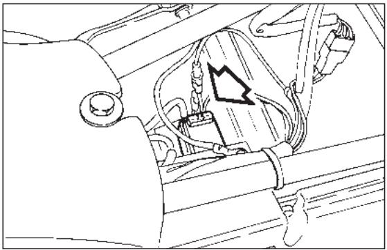
Fig. 71
FUSE REPLACEMENT (Fig. 71)
The fuse (7,5 A) is positioned under the saddle.
If any device ceases to operate, check the fuse that protects the circuit.
If the fuse is burnt-out the filament will be broken.
Before replacing the fuse, look, if possible, for the cause of the fault.
Then replace the fuse with another of the same type.

Never close the circuit with material other than the fuse.
ADJUSTING THE HEADLIGHT BEAM (Fig. 72-73)
To rapidly check the correct direction of the beam, place the vehicle on flat ground, 10m away from a wall. Turn on the low beam, sit on the vehicle and verify that the headlight beam projected on the wall is slightly under the horizontal line of the headlight (about 9/10th of the total length - Fig. 72).
To adjust the headlight beam:
Act on the apposite screw (Fig. 73)with a screw driver.
By SCREWING (clockwise), the beam sets upwards.
By UNSCREWING (anticlockwise), the beam sets downwards.
BULBS

Before changing a bulb, turn the ignition switch to the "×" position.
ing a clean and dry cloth.
Do not leave fingerprints on the bulbs, since you could cause their overheating and consequent breakage. If you touch the bulb with bare hands, remove any fingerprint with alcohol, in order to prevent it from frequently cutting out.
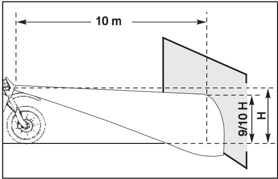
Fig. 72
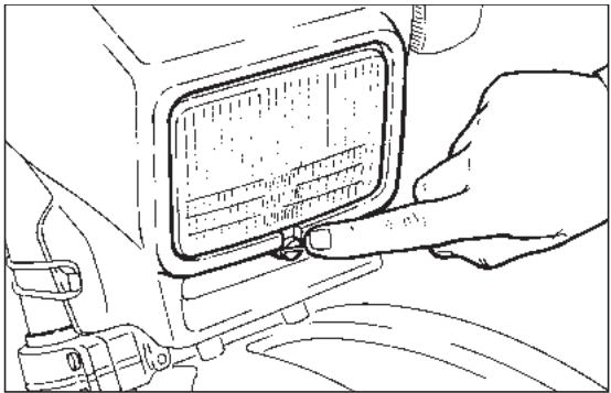
Fig. 73

Fig. 74
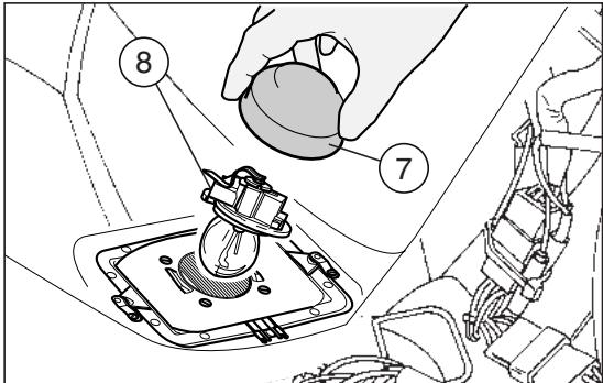
Fig. 75
CHANGING THE HEADLIGHT BULBS (Fig. 74)
To change the low and high beam bulbs, proceed as follows:

To extract the bulb electric connector, do not pull its electric wires.
Grasp the bulb electric connector (6), pull it and disconnect it from the bulb (2).
Withdraw the protection element (7) from the reflector and from the bulb terminals.
Rotate the bulb socket (8) anticlockwise and extract it from the reflector.
Extract the bulb (2).
For the installation:

Insert the bulb (2) in the reflector, making sure that the two teeth provided on the bulb coincide to the relevant guide on the reflector.
Position the bulb socket (8) in the reflector and rotate it clockwise.
Correctly insert the protection element (7) in the bulb terminals and in the reflector.
Connect the bulb electric connector (6).
PARKING LIGHT BULB

To extract the bulb socket, do not pull its electric wires.
Grasp the bulb socket, pull and disconnect it from its seat.
Withdraw the parking light bulb (9) and replace it with one of the same type.
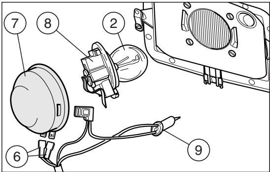
Fig. 76
CHANGING THE REAR LIGHT BULBS (Fig. 77)
Proceed as follows:
Unscrew the two screws (1);
Remove the glass (2);
Press the bulb (3) slightly and rotate it anticlockwise;
Remove the bulb from its seat.

The introduction of a new bulb can be carried out in one sense only, since the
two guide pins are misaligned.
Install a new bulb correctly, then repeat the above operations in the reverse order for the reassembly.
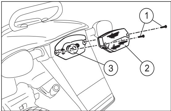
Fig. 77
CLEANING
We advise cleaning the vehicle frequently, not only for the sake of its appearance, but also because cleanliness helps to keep your vehicle in good condition and prolongs the life of its various parts.
Before cleaning vehicle, block off exhaust pipe, filter box intake holes and make sure that spark plug and carburettor are well assembled on bike.
Before cleaning, degrease the most exposed parts (engine) with suitable additives.
Then clean the vehicle with soapy water, using only natural water pressure to rinse it.

Do not use polishing pastes on matt paints.

Do not use alcohol, petrol or solvents to clean the rubber and plastic parts and the saddle: use only water and mild-soap.

Excessive pressure risks causing water infiltrations in the wheel bearings, front fork, brakes and linings, causing serious
da-image.
Then lubricate the chain and clean the air filter.
Do not apply protection waxes onto the saddle, in order not to make it too slippery.
LONG INACTIVITY
If the vehicle has to remain inactive for several months, we advise:
Clean and protect the painted parts with polish;
Disconnect the battery terminals;
- Check the state of battery charge every one and a half months. If it has to be recharged, use a trickle charge to avoid damaging the battery;
Remove all the fuel from the tank and empty the carburettor float chamber;
- Remove the spark plug and pour a teaspoon (5-10 cm³) of two-stroke engine oil into the cylinder. Then replace the spark plug and operate on the kick-starter a few times without inserting the key so as to spread the oil over the walls of the cylinders;
Check the tyre pressure from time to time;
Lubricate the chain.
TECHNICAL FEATURES
MOTOR
Model AM6
Type 2 stroke single-cylinder with lamellar inlet
Cooling............ Liquid with forced circulation
Lubrication . Separate
Bore / stroke. 40,3 mm / 39 mm
Displacement 49,75 cm3
Compression ratio 12,0±0,5:1
Rpm at idling speed 1,600±100
KICK START
To pedal (Kick-starter)
CLUTCH
Light alloy multiple disc oil bath
GEARS
Frontal clutch 6 speed unit
TRANSMISSION
Primary. Helical teeth gears
Ratio 3,55 (Z=20/71)
Secondary.........chain 1 / 2^ 3,16^ = Roller 07,75 mm
Ratio: 4,25 (Z=11/51)
CARBURETTOR
correspondent to 20^ before T.D.C.
Running-in (500 km) unleaded petrol
according to the DIN 51607 standard
min. O.N. 95 (N.O.R.M.)
and 85 (N.O.M.M.)
Aferwords: unleaded petrol
according to the DIN 51607
min. O.N. 95 (N.O.R.M.)
and 85 (N.O.M.M.)
Fuel tank capacity 9,5
Reserve (with mechanical operation) 1,5
Mixer oil tank capacity. 1,3
Reserve (with warning light on the dashboard)... 0,5
LUBRICATION
Gearbox and primary transmission .820 cm ^3 of oil (*)
COOLING
Cooling circuit capacity 0,9l ()
(60% antifreeze + 40% water)
Minimum operating temperature. 17^
FRAME
High-resistance one-beam structure, split over the exhaust
Steering head angle 26°
REAR FORK
Made of rectangular-profile steel, mounted on antifriction bushings
SUSPENSIONS
Front. upside-down 40 mm
Travel 260 mm
Rear . Gas-filled adjustable
monoshock absorber
Travel 100 mm
Rear wheel stroke 260 mm
BRAKES
Front. disc brake 230 mm
with hydraulic control
and floating caliper with two parallel pins
Rear . disc brake 220 mm
with hydraulic control
and fixed caliper
with two opposing pins 28mm
TYRES
Front. 80/90 x 21" Enduro-type
Inflation pressure (off-road) 1.0 bar
Inflation pressure (mixed road surface) 1.5 bar
Inflation pressure (asphalt) 1.6 bar
Rear 110/80 x 18" Enduro-type
Inflation pressure (off-road) 1.1 bar
Inflation pressure (mixed road surface) 1.6 bar
Inflation pressure (asphalt) 1.8 bar
RIMS
Front. 21 x 1,6"
Rear 18 x 1,85"
(*) see "LUBRICANT CHART"
DIMENSIONS
Max.length 2050mm
Max. width 820 mm
Max. height to handlebars. 1,200 mm
Seat height. 940 mm
Wheel base. 1,390 mm
Min. ground clearance 350 mm
Weight ready for starting. 104 Kg
Vehicle max. loading capacity
(rider + luggage). 75+30 Kg
ELECTRIC SYSTEM
Battery. 12 V - 4 Ah
Fuse. 7,5 A
BULBS
Low/high beams. 12 V - 35/35 W
Front parking light 12 V - 5 W
Direction indicators light. 12 V - 10 W
Rear parking /stop/number plate lights 12 V - 5/21 W
Dashboard light
(No. 2 bulbs. 12 V - 2 W)
WARNING LIGHTS
Gear in neutral 12 V - 2 W
Direction indicators 12 V - 2 W
Low beam 12 V - 2 W
High beam. 12 V - 2 W
Mixer oil level 12 V - 2 W
LUBRICANT CHART
Gearbox oil (recommended): F.C., SAE 75W - 90 or Agip GEAR SYNTH, SAE 75W - 90.
As an alternative to the recommended oil, it is possible to use high-quality oils with characteristics in compliance with or superior to the A.P.I. GL-4 specifications.
Mixer oil (recommended): GREEN HIT 2 or Agip City 2T.
As an alternative to the recommended oil, use high-quality oils with characteristics in compliance with or superior to the ISO-L-ETC++, A.P.I. TC++ specifications.
Fork oil (recommended): F.A. 5W or F.A. 20W as an alternative AGP FORK 5W or Agp FORK 20W.
If you need an oil with intermediate characteristics in comparison with the F.A. 5W and F.A. 20W or Agrip FORK 5W and Agrip FORK 20W, these can be mixed as indicated below:
SAE 10W = F.A. 5W 67 % of the volume ^+ F.A. 20W 33 % of the volume, or
AgFORK 5W 67 % of the volume ^+ AgFORK 20W 33 % of the volume, or.
SAE 15W = F. A. 5W 33% of the volume + F.A. 20W 67% of the volume, or
AgFORK 5W 33% of the volume ^+ AgFORK 20W 67 % of the volume.
Bearings and other lubrication points (recommended): AUTOGREASE MP - AGIP GREASE 30.
As an alternative to the recommended product, use high-quality grease for rolling bearings, working temperature range -30°C.... +140^ , dripping point 150^ ... 230^ , high protection against corrosion, good resistance to water and oxidation. Protection of the battery poles: neutral grease or vaseline.
Spray grease for chains (recommended): CHAIN SPRAY or Agip CHAIN LUBE.
WARNING
Use new brake fluid only. Do not mix different makes or types of oil without having checked bases compatibility..
Brake fluid: F.F. DOT 4 (brake system is also compatible DOT 5) - Agip BRAKE 5.1 DOT 4 (brake system is also compatible DOT 5).
WARNING
Use only nitrite-free anti-freeze and corrosion inhibitors with a freezing point of -35^ as a minimum.
Engine coolant (recommended): ECOBLU -40°C - AGP COOL.

APRILIA
via G. Galilei, 1 - 30033 Noale (VE) Italy
Tel. +39(0)41 5829111 - Fax +39(0)41 441054 - Servizio Clienti aprilia +39(0)41 5079821
UK APRILIA WORLD SERVICE UK branch
D APRILIA MOTORRAD
15 Gregory Way - SK5 7ST Stockport - Cheshire
Tel. 0044-161 475 1800 - Fax 0044-161 475 1825 - Email: massimo_granata@aprilia.com
Am Seestern 3 - D-40547 - Dusseldorf
Tel. 0049-211-59018-00 - Fax 0049-211-5901819 - Email: Ralf_kemper@aprilia.de
APRILIA WORLD SERVICE B.V.
C2 A. SPIRIT A.S.
A. SPIRIT A.S. (Sede operative)
z.a. Central Parc - 255 Blvd. R. Ballanger B.P. 77 - 93421-Vilpinte Tel.0033-149634747 Fax:0033-149638750 - Email: schwitzerina@aprila.fr
SLO AVTO TRIGLAVdo.o.
Saldova 38 - 180 00 - Praha 8 - Karlin
Bubenska 43-170 00-Praha 7
Tel.0042-02-96547142-Fax 0042-02-96547145-E-mail: pistek@aspirit.cz
A GINZINGER IMPORT GmbH & CO.
Baragova 5 - 1113 - Ljubljana
Tel. 00386-1-5883421 - Fax. 00386-1-5883465 - Email: ziga.martinicic@avto-triglay.si
HRING-KART d.o.o.
Frankenburgerstraße 19 - 4910 - Ried im Innkreis Tel. 0043-7752-88077 - Fax: 0043-7752-70684 - Email: office@aprilia.at
Samoborska cesta 258 - 10000 - Zagreb
Tel. 00385-1-3498000 - Fax: 00385-1-3499111 - Email: mario.petrusa@aprilia.hr
K.D.I. Kawasaki Distributor IRL. LTD:
no. 1 Long Mile Road - Dublin 12
Tel. 00353-1-4566222 - Fax: 00353-1-4756461 - Email: sales@bikeworld.ie
N HARO SKANDINAVIA A.S.
Kjorbebkalden 6-3735-Skien Tel.0047-35506780-Fax.0047-35506781-E-mail:ture@aprilia.no

MOTOMAX MOTORLU ARACLAR SAN.VET.C.A.S.
Kore Sehitleri Cad. No. 42 - 80300 - Zincirlikuyu - Istanbul
Tel. 0090-212-3360058 - Fax. 0090-212-3360057 - Email: aincili@motomax.com.tr

MILLE MOTOR KFT. (sede operativa)
No. 256, Sec. 2, Zhonghan Road, Taishan Township, Taipei County - 243 R.O.C Taipei
Tel. 00886-222970511 - Fax. 00886-222970569 - Email: twintwin2@ hotmail.com

ZED MOTORZ- Div. Of AL-RADWAN
INTERNATIONAL GROUP
Block 1, Street 13, Bldg 107, Shuwaikh Industrial 45703
Tel. 00965-4828072 - Fax: 00965-4828073 - Email: zed@zedmotorz.com

ACCESS INTERNATIONAL FOR
TRADING SARL.
Diamond Tower, 10th Floor P.O.B. 13 - Verdun, near Mandarine Beirut
Tel. 00961-1797333 - Fax. 00961-1798333 - Email: access_in@ hotmail.com

PT. MOTOR MEGA PERFORMA
Thanks to ongoing technical updates and product-specific technical training, aprilia Authorised Network engineers are familiar with every detail of this motorcycle and have the special equipment required for correct maintenance and repair.
A vehicle kept in sleek running order is a reliable vehicle. Pre-ride checks, proper maintenance at the recommended intervals and using aprilia Original Parts only are other key factors!
To find contact information of the Authorised Dealer and/or Service Centre nearest you, please consult the Yellow Pages or the map provided at our web site:
www.aprilia.com
When you demand aprilia Original Parts, you are purchasing products that have been developed and tested as early as the vehicle design stage. aprilia Original Parts systematically undergo strict quality control procedures to ensure total reliability and long service life.
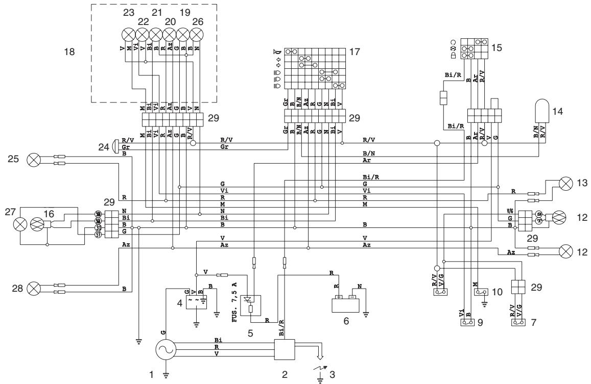
WIRING DIAGRAM - RX 50 Racing
WIRING DIAGRAM - RX 50 Racing
1) Generator
2) Ignition coil
3) Spark plug
4) Voltage regulator
5) Fuses
6) Battery
7) Front stoplight switch
8) Rear stoplight switch
9) Oil level sensor
10) Neutral indicator
11) Rear left direction indicator
12) Rear light
13) Rear right direction indicator
14) Blinking
15) Key-operated switch
16) Front twinlight (low/high beams)
17) Left dimmer switch
18) Complete dashboard
19) Dashboard lamps
20) Direction indicator warning light
21) Low beam warning light
21) High beam warning light
22) Oil level warning light
23) Neutral warning light
24) Horn
25) Front right direction indicator
26) Low beam bulb
27) Front parking light
28) Front left direction indicator
29) Multiple connectors
CABLE COLOURS
Ar Orange
Az Light blue
B Blue
Bi White
G Yellow
Gr Gray
M Brown
N Black
R Red
V Green
Vi Violet
aprilia s.p.a. wishes to thank its customers for the purchase of this vehicle.
- Do not dispose of used oil, fuel, polluting substances and components in the environment.
- Do not keep the engine running if it isn't necessary.
- Avoid disturbing noises.
- Respect nature.
- CATALYTIC SILENCER
- Reprint: October 2003
- VERSION:
- CONTENTS
- Pag.
- BASIC SAFETY RULES
- CLOTHING
- ACCESSORIES
- LOAD
- ARRANGEMENT OF THE CONTROLS
- KEY
- MULTIFUNCTION COMPUTER
- START-UP SETTING
- Metric system setting (KM/H or MPH)
- Setting the "WS" wheel diameter
- Pre-set value 2170.
- Time setting
- Preventative lubrication check
- Preventative maintenance check
- Checking the total distance covered (ODO)
- Checking the total race time (ART)
- Programming the second vehicle
- STANDARD SETTING
- PARAMETERS SETTING/DISPLAYING
- DISABLING THE SCHEDULED MAINTENANCE SERVICES
- CHRONOMETER
- RESETTING THE PARTIAL VALUES
- ALIGNING THE PARTIAL VALUES (TRIP)
- (RESETTING THE PARTIAL VALUES).
- BACKLIGHTING
- CHANGING THE BATTERY
- IGNITION SWITCH / STEERING LOCK / LIGHT SWITCH
- STEERING LOCK
- OPERATION
- CRASH-HELMET LOCK (Fig. 43)
- GLOVE / TOOL COMPARTMENT (Fig. 44)
- INSTRUCTIONS FOR USE
- The motor must not be filled with petrol/ oil mixed at filling stations.
- RUNNING
- STARTING (Fig. 45)
- COLD START
- MOVING OFF (Fig. 47)
- CHANGING GEAR (Fig. 47)
- STOPPING THE ENGINE
- MAINTENANCE
- See "PERIODIC MAINTENANCE CHART".
- REGULAR SERVICE INTERVALS CHART
- OPERATIONS TO BE CARRIED OUT BY THE aprilia Of-ficial Dealer.
- Carry out the maintenance operations more frequently if you use the vehicle in rainy and dusty areas or on uneven ground.
- IDENTIFICATION DATA
- FRAME NUMBER (Fig. 48)
- ENGINE NUMBER (Fig. 49)
- CHECKING THE GEAR OIL LEVEL (Fig. 50)
- GEAR OIL REPLACEMENT (Fig. 50)
- CLUTCH ADJUSTMENT (Fig. 51-52)
- SEPARATE LUBRICATION (Fig. 53-56)
- "TECHNICAL FEATURES").
- ADJUSTING THE REAR BRAKE (Fig. 55)
- CHECKING AND BLEEDING THE FRONT AND REAR BRAKE (Fig. 56)
- The bleeding operations for the front and rear braking system are the same.
- ADJUSTING THE REAR SUSPENSION (Fig. 59)
- CHAIN ADJUSTMENT (Fig. 60)
- For the wheel centering:
- CHAIN LUBRICATION (Fig. 61)
- CHAIN CHECKING (Fig. 62)
- AIR FILTER REMOVIDING AND CLEANING (Fig. 63)
- The filter must be well impregnated, though not dripping
- COOLANT CHECKING
- CHECKING AND TOPPING UP (Fig. 64)
- Be careful not to confuse the oil mixer tank with the expansion tank.
- Do not exceed this level, otherwise the fluid will overflow when the engine is running.
- If it is necessary to top up the coolant too frequently, contact your aprilia Official Dealer for a check.
- CHANGING THE COOLANT (Fig. 65-66)
- SPARK PLUG MAINTENANCE
- (Fig. 67)
- REGOLAZIONE DEL MINIMO (Fig. 68)
- ADJUSTING
- THE ACCELERATOR CONTROL (Fig. 69)
- ELECTRICAL SYSTEM
- BATTERY MAINTENANCE
- FUSE REPLACEMENT (Fig. 71)
- ADJUSTING THE HEADLIGHT BEAM (Fig. 72-73)
- BULBS
- CHANGING THE HEADLIGHT BULBS (Fig. 74)
- For the installation:
- PARKING LIGHT BULB
- CHANGING THE REAR LIGHT BULBS (Fig. 77)
- CLEANING
- LONG INACTIVITY
- TECHNICAL FEATURES
- MOTOR
- KICK START
- CLUTCH
- GEARS
- TRANSMISSION
- CARBURETTOR
- LUBRICATION
- COOLING
- FRAME
- REAR FORK
- SUSPENSIONS
- BRAKES
- TYRES
- RIMS
- DIMENSIONS
- ELECTRIC SYSTEM
- WARNING LIGHTS
- LUBRICANT CHART
- WARNING
- www.aprilia.com
- WIRING DIAGRAM - RX 50 Racing
- CABLE COLOURS
Brand : APRILIA
Model : RX 50 RACING
Category : Motorcycle