
RSV 1000 TUONO R - Motorcycle APRILIA - Free user manual and instructions
Find the device manual for free RSV 1000 TUONO R APRILIA in PDF.
| Product Type | Sport motorcycle |
| Brand | APRILIA |
| Model | RSV 1000 TUONO R |
| Dimensions (L × W × H) | 2025 × 830 × 1100 mm |
| Wheelbase | 1410 mm |
| Seat height | 810 mm |
| Ground clearance | 150 mm |
| Weight (ready to start) | 209 kg |
| Engine | 4-stroke, V 60° twin cylinder, DOHC, 4 valves per cylinder |
| Displacement | 997.6 cm³ (bore 97 mm, stroke 67.5 mm) |
| Compression ratio | 11.8:1 |
| Fuel system | Multi-point electronic injection |
| Fuel | Unleaded gasoline, octane rating ≥ 95 (RON) |
| Fuel tank capacity | 18 L (reserve 4 L) |
| Transmission | 6-speed manual, chain 525 |
| Front brake | Double floating disc Ø 320 mm, 4-piston calipers |
| Rear brake | Disc Ø 220 mm, 2-piston caliper |
| Front suspension | Adjustable inverted fork Ø 43 mm, travel 120 mm |
| Rear suspension | Double-sided swingarm, adjustable shock absorber, travel 133 mm |
| Tires | Front: 120/70 ZR17, Rear: 190/50 ZR17 (alternative 180/55) |
| Lighting | H11 halogen headlights 12V 55W (×4), position lights 5W, turn signals 10W, LED brake light |
| Battery | 12 V - 10 Ah |
| Engine oil capacity (drain) | 3700 cm³ (with filter: 3900 cm³) |
| Coolant | 2.2 L (50% water + 50% antifreeze) |
| Maintenance | Oil change every 10,000 km, NGK DCPR9E spark plugs, hydraulic brakes and clutch |
Frequently Asked Questions - RSV 1000 TUONO R APRILIA
User questions about RSV 1000 TUONO R APRILIA
0 question about this device. Answer the ones you know or ask your own.
Ask a new question about this device
Download the instructions for your Motorcycle in PDF format for free! Find your manual RSV 1000 TUONO R - APRILIA and take your electronic device back in hand. On this page are published all the documents necessary for the use of your device. RSV 1000 TUONO R by APRILIA.
USER MANUAL RSV 1000 TUONO R APRILIA
First edition: October 2005
Reprint:
Produced and printed by:
VALLEY FORGE DECA
Ravenna, Modena, Torino
DECA S.r.l.
The following precautionary warnings are used throughout this manual in order to convey the following messages:
Safety warning. When you find this symbol on the vehicle or in the manual, be careful to the potential risk of personal injury. Non-compliance with the indications given in the messages preceded by this symbol may result in grave risks for your and other people's safety and for the vehicle!

WARNING
Indicates a potential hazard which may result in serious injury or even death.

CAUTION
Indicates a potential hazard which may result in minor personal injury or damage to the vehicle.
NOTE The word "NOTE" in this manual precedes important information or instructions.
TECHNICAL INFORMATION
The operations preceded by this symbol must be repeated also on the opposite side of the vehicle.
If not expressly indicated otherwise, for the reassembly of the units repeat the disassembly operations in reverse order.
The terms "right" and "left" are referred to the rider seated on the vehicle in the normal riding position.
If the glove/tool kit compartment cover has been installed (as an alternative to the passenger seat), the transport of passenger, luggage or objects is forbidden.

WARNING
Racing settings may only be used during official competitions or sports events authorised by the competent authorities and taking place in closed circuits or, anyway, away from public roads.
It is strictly prohibited to carry out adjustments for the use of the vehicle on racetracks and then ride it on roads or motorways.
WARNING - PRECAUTIONS - GENERAL ADVICE
Before starting the engine, carefully read this manual and in particular the section "SAFE DRIVE".
Your and other people's safety depends not only on your quickness of reflexes and on your agility, but also on what you know about the vehicle, on its efficiency and on your knowledge of the basic information for "SAFE DRIVE".
Therefore, get a thorough knowledge of the vehicle, in such a way as to be able to ride in the traffic safely.
NOTE This manual must be considered as an integral part of the vehicle and must always accompany it, even in case of resale.
aprilia has carried out this manual with the maximum attention, in order to supply the user with correct and updated information. However, since aprilia constantly improves the design of its products, there may be slight discrepancies between the characteristics of your vehicle and those described in this manual.
For any clarification concerning the information contained in this manual, do not hesitate to contact an aprilia Authorised Dealer.
For inspections and repair operations not expressly described in this publication, for the purchase of aprilia genuine spare parts, accessories and other products, as well as for specific advice, contact exclusively aprilia Authorised Dealers and Service Centres, which guarantee prompt and accurate assistance.
Thank you for choosing aprilia. We wish you a nice ride.
All rights as to electronic storage, reproduction and total or partial adaptation, with any means, are reserved for all Countries.
NOTE In some countries the antipollution and noise regulations in force require periodical inspections.
The user of the vehicle in these countries must:
- contact an aprilia Authorised Dealer to have the non-homologated components replaced with others homologated for use in the country in question;
- carry out the required periodical inspections.
NOTE Soon after purchasing the vehicle, write down the identification data indicated on the SPARE PARTS IDENTIFICATION LABEL in the table here below. This label is positioned on the left side of the frame; to read it, it is necessary to remove the rider seat, see page 77 (REMOVING THE RIDER SEAT).
| I | UK | A | P | SF | B | D | F | E | GR |
| NL | CH | DK | J | SGP | SLO | IL | ROK | MAL | RCH |
| HR | AUS | USA | BR | RSA | NZ | CDN |
These data indicate:
- YEAR = year of manufacture (Y, 1, 2, ...);
- I.M. = modification code (A, B, C, ...);
- COUNTRY CODES = homologation country (I, UK, A, ...).
and are to be supplied to the aprilia Authorised Dealer as reference data for the purchase of spare parts or specific accessories of the model you have acquired.
Market versions are identified by the following symbols throughout the manual:
OPT optional
catalytic version
VERSION:
| Italy | SGP | Singapore |
| United Kingdom | SLO | Slovenia |
| A Austria | IL | Israel |
| Portugal | ROK | South Korea |
| Finland | MAL | Malaysia |
| Belgium | RCH | Chile |
| Germany | HR | Croatia |
| France | AUS | Australia |
| Spain | USA | United States America |
| Greece | BR | Brazil |
| Holland | RSA | South Africa |
| Switzerland | NZ | New Zealand |
| Denmark | CDN | Canada |
| Japan |
TABLE OF CONTENTS
SAFETYWARNINGS 2
TECHNICAL INFORMATION 2
WARNING - PRECAUTIONS - GENERAL ADVICE 2
TABLE OF CONTENTS 4
BASIC SAFETY RULES 6
CLOTHING 8
ACCESSIONS 8
LOAD 9
ARRANGEMENT OF THE MAIN ELEMENTS 10
ARRANGEMENT OF THE
INSTRUMENTS/CONTROLS 12
INSTRUMENTS AND INDICATORS 13
INSTRUMENTS AND INDICATORS TABLE..... 14
MULTIFUNCTION COMPUTER 16
SERVICEINTERVAL 22
ALARM DISPLAY 22
KEY CONTROLS 22
KEY CONTROLS 23
Luggage FIXING POINTS 27
SPECIAL TOOLS 28
MAIN COMPONENTS 29
FUEL 29
BRAKE FLUID - recommendations 30
DISC BRAKES 31
FRONT BRAKE 32
REAR BRAKE 34
CLUTCH FLUID - recommendations 35
CLUTCH 36
COOLANT 37
TYRES 40
ENGINE OIL 41
GETTING ON AND OFF THE VEHICLE 44
PRE-RIDE CHECKS 46
PRE-RIDE CHECKS CHART 47
STARTING 48
MOVING OFF - RIDING 50
RUNNING-IN 54
STOPPING 54
PARKING 55
PLACING THE VEHICLE ON THE STAND. 56
SUGGESTIONS TO PREVENT THEFT 57
MAINTENANCE 58
REGULAR SERVICE INTERVALS CHART... 59
IDENTIFICATION DATA 61
JOINTS WITH CLICK CLAMPS AND WITH SCREW CLAMPS. 61
CHECKING AND TOPPING UP ENGINE OIL LEVEL 62
CHANGING ENGINE OIL AND THE ENGINE OIL FILTER 63
AIR FILTER 66
FITTING THE PINS FOR THE REAR
WHEEL STAND 67
POSITIONING THE VEHICLE ON THE REAR SUPPORT STAND 67
POSITIONING THE VEHICLE ON THE FRONT
SUPPORT STAND 68
FRONT WHEEL 68
REMOVING THE RIDER SEAT 77
LIFTING THE FUEL TANK 77
REMOVING THE SIDE FAIRINGS 78
REMOVING THE SIDE PANELS 82
REMOVING THE REAR-VIEW MIRRORS 83
REMOVING THE SIDE STAND 83
INSPECTING THE FRONT AND REAR SUSPENSIONS 85
FRONT SUSPENSION 86
STEERING DAMPER 88
REAR SUSPENSION 88
CHECKING THE BRAKE PADS FOR WEAR.... 90
ADJUSTING THE THROTTLE TWISTGRIP.... 91
SPARK PLUGS 92
CHECKING THE SIDE STAND 94
BATTERY 95
CLEANING AND CHECKING BATTERY
TERMINALS AND LEAD CONNECTIONS 95
REMOVING THE BATTERY 96
CHECKING BATTERY FLUID LEVEL 97
CHARGING THE BATTERY 97
INSTALLING THE BATTERY 98
LONG INACTIVITY OF THE BATTERY 99
CHECKING THE SWITCHES 99
REPLACING THE FUSES 100
VERTICAL ADJUSTMENT OF THE HEADLIGHT BEAM 101
TAPING OF THE HEADLIGHT 102
BULBS. 103
REPLACING THE INSTRUMENT PANEL LED 103
CHANGING THE HEADLIGHT BULBS 104
CHANGING THE FRONT AND REAR
TURN INDICATOR BULBS 105
REPLACING THE NUMBER PLATE LIGHT BULB 106
TRANSPORT 107
Cleansing 107
LONG PERIODS OF INACTIVITY 109
TECHNICAL DATA 110
LUBRICANT CHART 114
WIRING DIAGRAM RSV 1000 TUONO R..... 116
WIRING DIAGRAM KEY - RSV 1000 TUONO R. 117
AUTHORISED DEALERS AND SERVICE CENTRES 120

safe drive
BASIC SAFETY RULES
To ride the vehicle it is necessary to be in possession of all the requirements prescribed by law (driving licence, minimum age, psychophysical ability, insurance, state taxes, vehicle registration, number plate, etc.).
Gradually get to know the vehicle by driving it first in areas with low traffic and/or private areas.
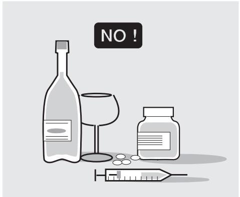
The use of medicines, alcohol and drugs or psychotropic substances notably increases the risk of accidents.
Be sure that you are in good psychophysical conditions and fit for riding and pay particular attention to physical weariness and drowsiness.
Most road accidents are caused by the rider's lack of experience.
NEVER lend the vehicle to beginners and, in any case, make sure that the rider has all the requirements for driving.
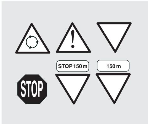
Rigourously observe all road signs and national and local road regulations.
Avoid abrupt movements that can be dangerous for yourself and other people (for example: wheeling, speeding, etc.); and give due consideration to the road surface, visibility and other driving conditions.
Avoid obstacles that could damage the vehicle or make you lose control.
Avoid riding in the slipstream created by preceding vehicles in order to increase your speed.
WARNING
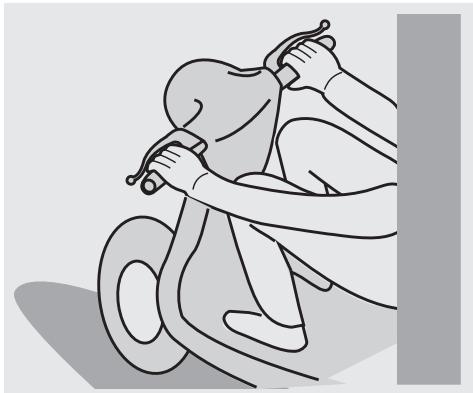
Always drive with both hands on the handlebars and both feet on the footrests (or on the rider's footboards), in the correct driving posture.
CAUTION
Avoid standing up or stretching your limbs while driving.
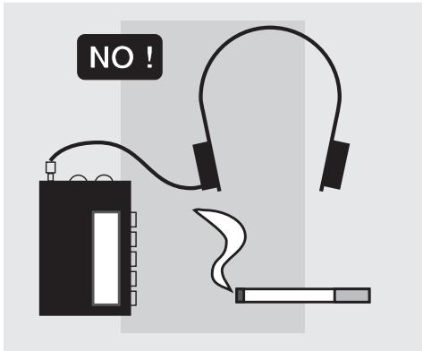
The rider should pay attention and avoid distractions caused by people, things and movements (never smoke, eat, drink, read, etc.) while driving.
Use only the vehicle's specific fuels and lubricants indicated in the "LUBRICANT CHART"; check all oil, fuel and coolant levels regularly.
If the vehicle has been involved in an accident, make sure that no damage has occurred to the control levers, pipes, wires, braking system and vital parts.
If necessary, have the vehicle inspected by an aprilia Authorised Dealer who should carefully check the frame, handlebars, suspensions, safety parts and all the devices that you cannot check by yourself.
Always remember to report any malfunction to the technicians to help them in their work.
Never use the vehicle when the amount of damage it has suffered endangers your safety.
Never change the position, inclination or colour of: number plate, direction indicators, lights and horns.
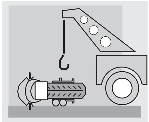
Any modification of the vehicle will result in the invalidity of the guarantee.
Any modification of the vehicle and/or the removal of original components can compromise vehicle performance levels and safety or even make it illegal to ride.
We recommend respecting all regulations and national and local provisions regarding the equipment of the vehicle.
In particular, avoid all modifications that increase the vehicle's performance levels or alter its original characteristics.
Never race with other vehicles.
CLOTHING
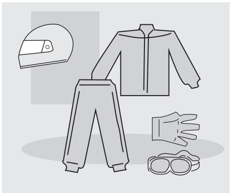
Before starting, always wear a correctly fastened crash helmet. Make sure that it is homologated, in good condition, of the right size and that the visor is clean.
Wear protective clothing, preferably in light and/or reflecting colours. In this way you will make yourself more visible to the other riders, thus notably reducing the risk of being knocked down, and you will be more protected in case of fall.
This clothing should be very tight-fitting and fastened at the wrists and ankles; strings, belts and ties should not be hanging loose; prevent these and other objects from interfering with driving by getting entangled with moving parts or driving mechanisms.
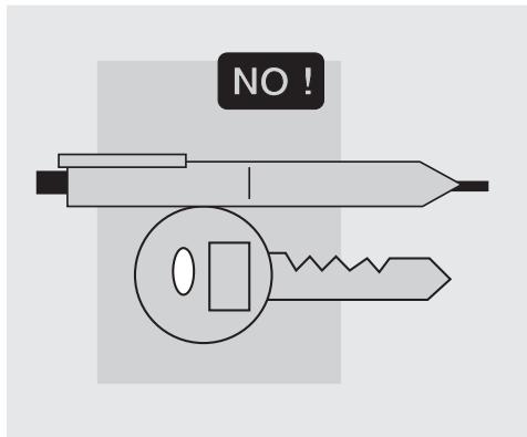
Do not keep objects that can be dangerous in case of fall, for example pointed objects like keys, pens, glass vials etc. in your pockets (the same recommendations also apply to a possible passenger).
ACCESSORIES
The owner of the vehicle is responsible for the choice, installation and use of any accessory.
Avoid installing accessories that cover horns or lights or that could impair their functions, limit the suspension stroke and the steering angle, hamper the operation of the controls and reduce the ground clearance and the angle of inclination in turns.
Avoid using accessories that hamper access to the controls, since this can prolong reaction times during an emergency.
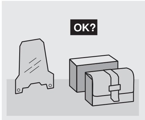
Big fairings and windshields installed on the vehicle may produce aerodynamic forces that affect the stability of the vehicle, especially when riding at high speed.
Make sure that the equipment is well fastened to the vehicle and not dangerous during driving.
Do not install electrical devices and do not modify those already existing to avoid electrical overloads, because the vehicle could suddenly stop or there could be a dangerous current shortage in the horn and in the lights.
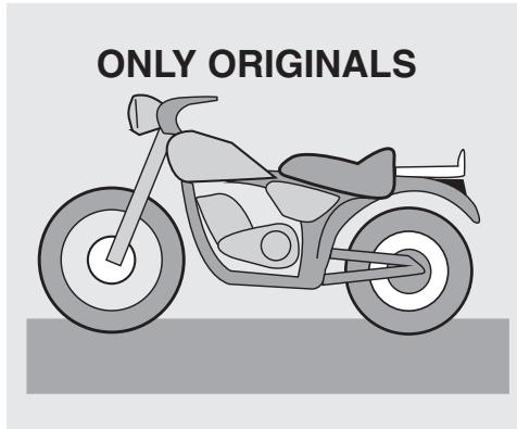
aprilia recommends the use of genuine accessories (aprilia genuine accessories).
LOAD
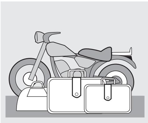
Be careful and moderate when loading your luggage. Keep any luggage loaded as close as possible to the centre of gravity of the vehicle and evenly distribute the load on both sides, in order to reduce unbalance to the minimum.
Furthermore, make sure that the load is firmly secured to the vehicle, especially during long trips.
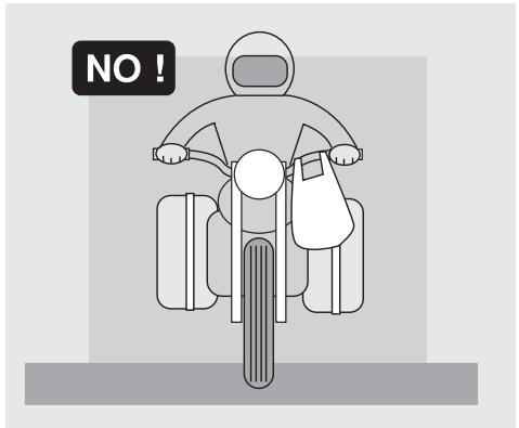
Avoid hanging bulky, heavy and/or dangerous objects on the handlebars, mudguards and forks, because the vehicle might respond more slowly in turns and its manoeuvrability could be unavoidably impaired.
Do not place bags that are too bulky on the vehicle sides and do not ride with the crash helmet hanging on one side, because they could hit people or obstacles, making you lose control of the vehicle.
Do not carry any bag if it is not tightly secured to the vehicle.
Do not carry bags which protrude too much from the luggage-rack or which cover the lights, horn or indicators.
Do not carry animals or children on the glove compartment or on the luggage rack.
Do not exceed the maximum load allowed for each bag.
When the vehicle is overloaded, its stability and its manoeuvrability can be compromised.
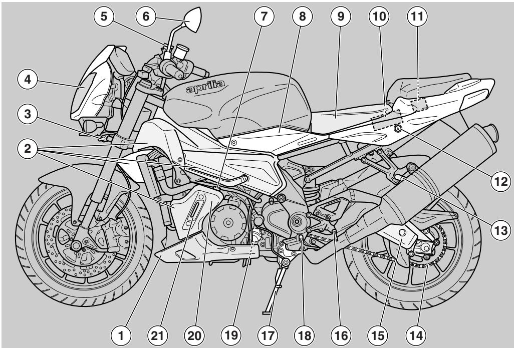
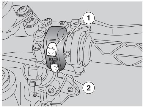
KEY
1) Fairing lug
2) Side fairings
3) Adjustable steering damper
4) Left headlight
5) Clutch fluid reservoir
6) Left rear-view mirror
7) Engine oil reservoir plug
8) Left side body panel
9) Rider seat
10) Battery
11) Main fuse carrier (30A)
12) Passenger seat-glove/tool kit compartment lock
13) Passenger left footrest (snapping, closed/open)
14) Drive chain
15)Swinging arm
16) Rider left footrest
17) Side stand
18) Gear shift lever
19) Engine oil filter
20) Engine oil tank
21) Engine oil level
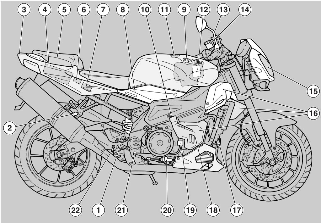
KEY
1) Rear shock absorber
2) Passenger right footrest (snapping, closed/open)
3) Tail light
4) Glove/tool kit compartment
5) Passenger seat / Seat cover
6) E.C.U.
7) Secondary fuse carrier (15A)
8) Right side body panel
9) Fuel tank
10) Coolant expansion tank cap
11) Fuel tank filler cap
12) Air filter
13) Right rear-view mirror
14) Front brake fluid tank
15) Right headlight
16) Right side fairings
17) Horn
18) Expansion tank
19) Rear brake fluid tank
20) Rear brake master cylinder
21) Rear brake control lever
22) Rider right footrest
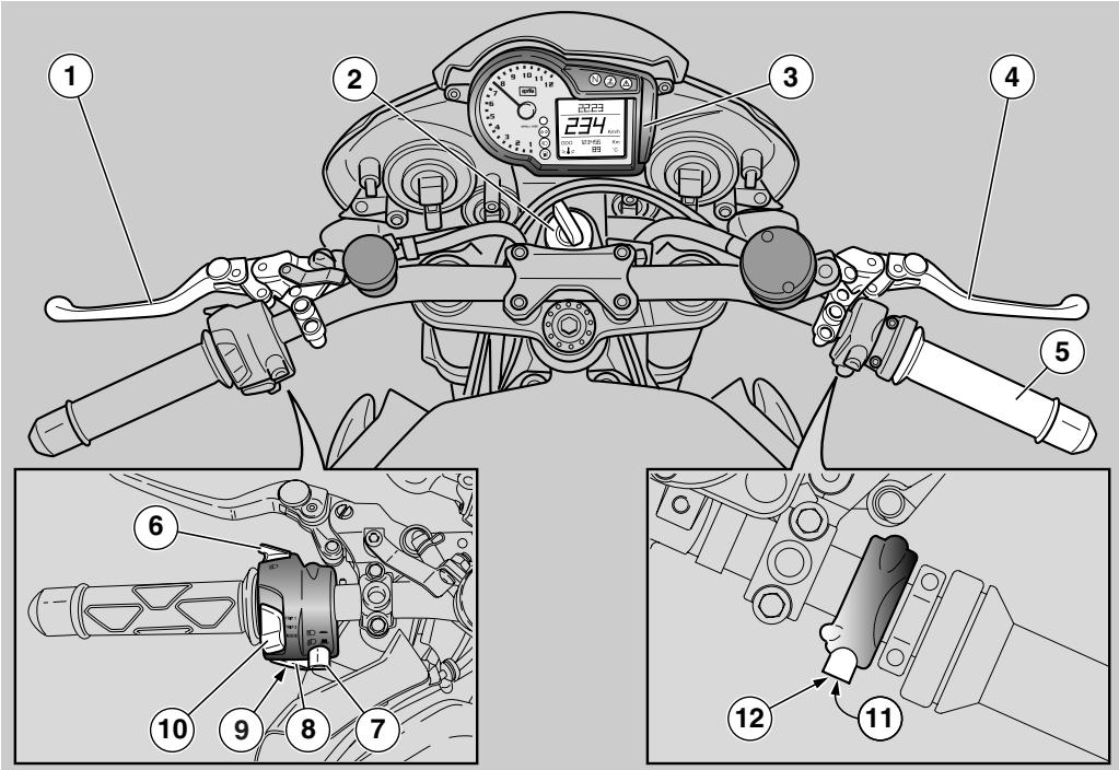
KEY
1) Clutch lever
2) Ignition switch/steering lock (O-1
3) Instruments and indicators
4) Front brake lever
5) Throttle grip
6) High beam flasher - passing button (D)
7) Dimmer switch (D-D)
8) Turn indicator switch ()
9) Horn button ()
10)TRIP 1/TRIP2/MODE switch
11) Engine kill switch (O - - 8)
12) Starter button (①)
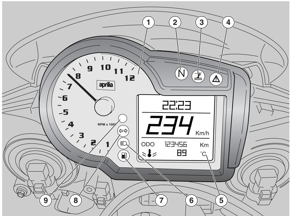
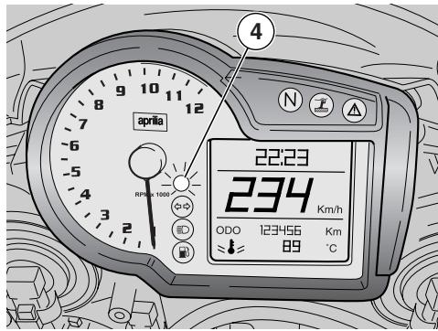
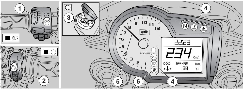
KEY
1) Revolution counter
2) Green neutral light (N)
3) Amber "stand down" light (J)
4) Red general warning light ()
5) Multifunction digital display (coolant temperature - clock - battery voltage - lap timer - engine oil pressure diagnostics
6) Blue high beam warning light (E D)
7) Amber low fuel warning light (B)
8) Green turn indicator warning light ( )
9) Red line light
INSTRUMENTS AND INDICATORS TABLE
When the ignition key is turned to "O" with the engine stopped, all warning lights come on for a LED check-up and go out after two seconds. If one or more warning lights do not come on at this stage, contact an aprilia Authorised Dealer.
| Description | Function | ||
| Revolution counter rpm | Indicates the number of revolutions of the engine per minute. ▲ CAUTION Never exceed the engine max. speed rate, see page 54 (RUNNING-IN). | ||
| Gear shift light | Blinks when activation threshold (max. rpm) set by the user is exceeded, see page 19 (GEAR SHIFT INDICATOR). | ||
| Direction indicator warning light ⇌ | Blinks when the direction indicators are on. | ||
| High beam warning light ≅O | Comes on when the high beam bulbs are on or when the headlight signaller is operated. | ||
| Side stand down light ↕ | Turns on when the side stand is down. | ||
| Low fuel warning light ↕ | It comes on when the quantity of fuel left in the tank is approx. 4,5 ± 1/2. In this case, top up as soon as possible, see page 29 (FUEL). | ||
| Neutral indicator warning light N | Comes on when the gear is in neutral. | ||
| Error warning light ↕ | Comes on when the ignition switch is set to " ○" with the engine stopped as a lamp test. If the light does not come on in this phase, contact an aprilia Authorised Dealer. When engine is off it indicates that immobiliser system is enabled. ▲ CAUTION If the light △ remains on after the engine start or comes on during the normal operation of the engine, this means that a fault of the injection system was detected and, if it is displayed simultaneously with the symbol "▽", a low engine oil pressure was detected. In this case, stop the engine immediately and contact an aprilia Authorised Dealer. | ||
| Description | Function | ||
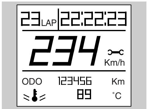
| Multifunction digital display | Speedometer (km/h - MPH) | Displays current, average or maximum riding speed (in kilometres or miles) depending on pre-setting, see page 16 (MULTIFUNCTION COMPUTER). | |
| Odometer (KM - Mi) | Gives total distance covered or distance covered since the trip meter was last reset (in km or miles). | ||
| Coolant temperature (°C/°F) | Displays engine coolant temperature, see page 16 (MULTIFUNCTION COMPUTER).If the pointer gets near the danger area, stop the engine, turn the key to "○" and wait until the cooling fan is disconnected.▲ CAUTION Do not leave the ignition switch on "×", since the cooling fans would stop regardless of the coolant temperature and in this case the temperature would increase even further. Now turn the key to "×" and check coolant level, see page 37 (COOLANT).Contact an aprilia Authorised Dealer.▲ CAUTION If the maximum allowed temperature is exceeded (115 °C - 239 °F), the engine may be seriously damaged. | ||
| Clock | Displays time (hour and minutes) as preset, see page 16 (MULTIFUNCTION COMPUTER). | ||
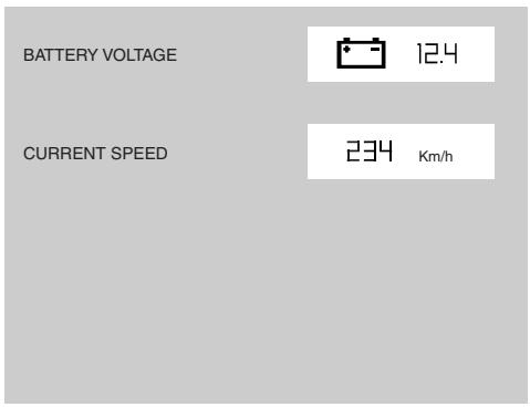
| Battery voltage V BATT | Displays the battery voltage in Volts, see page 16 (MULTIFUNCTION COMPUTER). | ||
| Lap timer | Displays the different lap times, as preset, see page 16 (MULTIFUNCTION COMPUTER). | ||
| Diagnosis | In case a serious failure is detected, one that might jeopardise the vehicle or the rider's safety, the panel will show an icon indicating the failure cause (such as: oil pressure ×, maintenance intervals ×).▲ CAUTION If the wording "△ SERVICE" appears during normal engine operation, it means that the ECU or the instrument panel have detected a failure. In many cases the engine keeps running with limited performance; contact an aprilia Authorised Dealer immediately. | ||
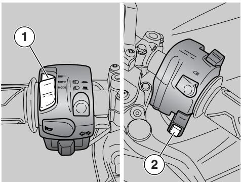
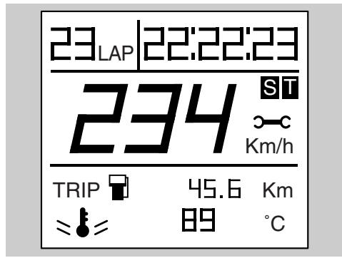
MULTIFUNCTION COMPUTER
Controls
1) Switch with three positions: TRIP1 / TRIP2 / MODE
2) SET button; briefly press it to scroll the functions in the menus, press for several seconds to confirm selected option.
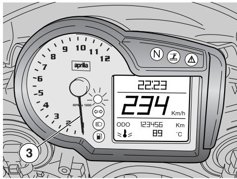
When you turn the ignition key to "O", the following instrument panel lights will turn on for 2 seconds:
- All warning lights
- Backlighting
- The display shows the Tuono 1000 logo.
The pointer of revolution counter (3) reaches the set gear shift value (rpm) and then goes back immediately to zero.
During the initial check-up, all instruments will briefly show the current values of the corresponding parameters.
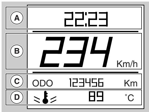
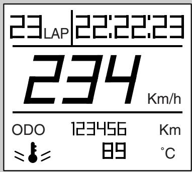
When the key is on "O", the following standard settings are displayed:
-Clock or lap timer (^*) zone A)
-Current speed (zone B)
- Odometer (zone C)
-Coolant temperature (zone D)
(*) According to settings entered in MENU, see page 18 (MENU) the displayed value may vary.
TRIP 1 AND 2
In TRIP 1 and 2 the data concerning trip 1 and 2 are shown.
Displayed trip meter indication can be found next to value description.
Set selector (1) to the position corresponding to TRIP configuration to be displayed (TRIP 1 or TRIP 1).
At the bottom (C) are the following data:
-TRIP METER 1/2
-TRIP TIME 1/2
-MAXIMUM SPEED 1/2
-AVERAGE SPEED 1/2
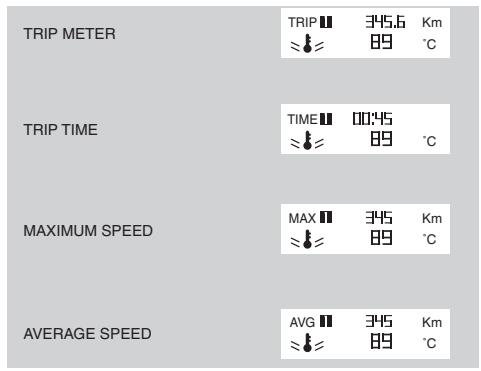
Briefly press SET (2) to toggle between these parameters. Press it for several seconds to reset all data from selected TRIP meter.
Mode
MODE configuration features the functions allowing the user to interact with the system.
Set selector (1) to MODE position to select MODE configuration.
While the vehicle at rest, the following data are alternately displayed every time the SET button (2) is pressed:
-CURRENT SPEED
-BATTERY VOLTAGE
Press SET (2) button for several seconds to enter the configuration menu:
-MENU
When reserve km indication is active, it replaces the odometer.
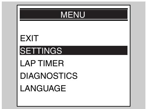
Menu
If vehicle is stopped and selector is set to MODE, configuration menu of the MENU page can be accessed. To enter this function, confirm MENU selection [press SET button (2) for several seconds].
Configuration menu options are:
-EXIT
- SETTINGS
-LAP TIMER
-DIAGNOSTICS
-LANGUAGE
SETTINGS
When confirming SETTINGS selection (pressing SET button (2) for several seconds) the following options are displayed:
-EXIT
-TIME SETTINGS
-GEAR SHIFT INDICATOR
-BACK LIGHTING
-CHANGE THE CODE
-CODE RECOVERY
-°C/°F
TIME SETTINGS
This mode allows you to set the clock. In this function, hours increase by one unit every time the SET button (2) is pressed; when value is 12, it goes back to 1 if the SET button (2) is pressed again.
AM indication becomes PM or vice versa when time goes from 11:59 to 12:00.
Press the SET button (2) for several seconds to store the value and go to minutes setting mode. Minutes increase by one unit every time the SET button (3) is pressed; when value is 59, it goes back to 0 if the SET button (2) is pressed again. Press the SET button (2) for several seconds to complete the procedure; the instrument panel sets back to SETTINGS menu.
GEAR SHIFT INDICATOR
This function allows you to set the value for the gear shift indicator threshold. As soon as you enter this function, the display shows "GEAR SHIFT INDICATOR" (if English is the selected language) and the rev. counter index indicates the threshold value.
Briefly press the SET (2) push-button to increase threshold value by 100 RPM. Once the max. value has been reached, press the push-button again to decrease the value and vice versa.
Press the SET button (2) for several seconds to complete the operation; the display sets back to SETTINGS menu.
When battery is connected for the first time, the instrument panel sets to running-in rpm value, the next time battery is connected it sets to last set value.
RUNNING-IN RPM: 6000
MINIMUM RPM: 5000
MAXIMUM RPM: 12000
When the set threshold is exceeded, the alarm light (4) on the instrument panel flashes until the value goes below the threshold.
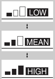
BACK LIGHTING
This function allows you to set backlighting: three levels are available. In this function the display shows "BACKLIGHTING" and every time SET (2) button is briefly pressed, the following symbols are alternatively displayed:
-LOW
-MEAN
-HIGH
Press the SET button (2) for several seconds to complete the operation; the instrument panel sets back to SETTINGS menu.
CHANGE THE CODE
This function is used when the old code is available and is to be changed.
Within this function, the following message is displayed:
"INSERT THE OLD CODE"
As soon as the old code is acknowledged, the new code is requested; the following message is displayed:
"INSERT THE NEW CODE"
Once the operation is over, the display goes back to DIAGNOSIS menu. If you entered with the code, this operation will not be allowed.
Once the operation is over, the instrument panel goes back to SETTINGS menu.
CODE RECOVERY
This function is used when the old code is not available and you need to change it. In this case it is necessary to insert at least two keys in the ignition switch. The first key is already inserted, a second key is requested with the message:
"INSERT THE 2nd KEY"
The instrument panel remains on in between these two keys; if the second key is not inserted within 20 seconds the operation is aborted. When the second key is acknowledged, the new code is requested with the message:
"INSERT THE NEW CODE"
Once the operation is over, the display goes back to DIAGNOSIS menu. If you entered with the code, this operation will not be allowed.
Once the operation is over, the instrument panel goes back to SETTINGS menu.
^ C / F
This function allows you to select the unit of measurement for ambient temperature. From this function, every time the SET button (2) is briefly pressed, the following two units of measurement are alternately displayed:
^ C
^ F
Press the SET button (2) for several seconds to store the data; the instrument panel sets back to SETTINGS menu.
Lap timer
When confirming LAP TIMER selection [pressing SET button (2) for several seconds] the following options are displayed:
-EXIT
-ENABLE LAP TIMER
-VIEW TIMES
-DELETE TIMES
ENABLE LAP TIMER
This function enables lap timer operation. Lap time is shown on display upper area, in place of the clock.
The display maintains this operation mode even after key-off/key-on.
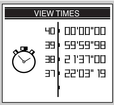
VIEW TIMES
This function also displays the acquired lap times. Briefly press the SET button (2) to scroll the pages with the times measured; press it for several seconds to set the display to LAP TIME menu. If the battery is disconnected, stored times are lost.
DELETE TIMES
This function deletes the acquired lap times. Deletion should be confirmed. Once the operation is over, the display goes back to LAP TIMER menu.
Lap time operation
Select ENABLE LAP TIMER and confirm (by pressing SET (2) button for several seconds) and display top zone (A) is automatically set for time recording. Briefly press SET button (2) to start recording with the lap timer.
Press again the SET button (2) within the first 10 seconds from when the timer starts, time measurement is cancelled and a new one is started. Press again the SET button (2) after 10 seconds have elapsed from timer start, time measurement is stopped, stored and a new one is started. Stop the time measurement session by pressing the SET (2) push-button for several seconds.
Acquisition ends as soon as 40 lap times are stored; "FULL" is displayed. Stop the vehicle, see page 54 (STOPPING) and enter the VIEW TIMES function of the LAP TIME menu to read the stored lap times.
Diagnosis
This function interfaces with the systems fitted to the motorcycle to carry out diagnosis. To enable it, you need a special password only available to the aprilia Authorised Service Centres .
Language
This function allows you to choose the language of any message displayed.
Available options are:
-ITALIANO
-ENGLISH
-FRANCAIS
-DEUTSCH
-ESPANOL
Once the operation is over, the display goes back to LANGUAGE menu.
SERVICE INTERVAL
When the scheduled service intervals are reached, an icon is displayed (symbol of a spanner).
Switches on first at: 1,000km
Then switches on: every 10,000km
This indication can be eliminated as soon as aprilia Authorised Dealers and Service Centres carry out the necessary scheduled maintenance operations.
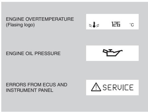
ALARM DISPLAY
In case a serious failure is detected, one that might jeopardise the vehicle or the rider's safety, the display will show an icon indicating the failure cause, at the bottom (D).
Alarms are divided in two groups depending on their priority:
High priority: engine overtemperature, engine oil pressure, faults from E.C.U., instrument panel faults.
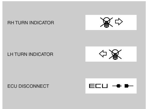
Low priority: turn indicators and control unit disconnect.
Should there be many alarms with same priority level, the relevant icons are displayed alternatively.
High priority alarms do not allow you to display low priority ones.
If the alarm light and the SERVICE icon briefly come on, it does not mean that there is a failure.
NOTE The electric components only operate when the ignition switch is in the "O" position.
1) ENGINE STOP SWITCH (O - - )
CAUTION
Do not operate the engine stop switch " 一 - 一 " while riding.
This switch serves as a safety or emergency switch.
With the switch pressed in position "O", it is possible to start the engine; the engine can be stopped by pressing the switch to position "O".
CAUTION
With the engine stopped and the ignition switch in position "■○", the battery may run flat.
CAUTION
When the vehicle has come to a standstill and you have stopped the engine, set the ignition switch to position " X".
2) STARTER BUTTON (①)
When the starter button " () is pressed, the starter motor will crank the engine. For the starting procedure, see page 48 (STARTING).
CONTROLS ON THE LEFT SIDE OF THE HANDLEBAR
NOTE The electric components only operate when the ignition switch is in the "O" position.
3) Horn button ()
The horn is activated when the push button is pressed.
4) Turn indicator switch (←→)
To indicate the turn to the left, move the switch to the left; to indicate the turn to the right, move the switch to the right.
Press the switch to turn off the direction indicator.
5) DIMMER SWITCH (D - D) When it is in position "D", the parking lights, the dashboard light and the low beam are always on.
When it is in position “ D ”, the high beam comes on.
Ensure that the dimmer switch is set to "■D" before starting the engine.
6) MULTIFUNCTION DISPLAY CONFIGURATION SELECTOR
Sets the configuration shown on display, see page 16 (MULTIFUNCTION COMPUTER).
7) High beam flasher - passing button (E0)
It makes it possible to use the high beam for signalling to forthcoming vehicles while overtaking and in case of peril and/or emergency.
NOTE Release the button to turn off the high beam flasher.
8) MULTIFUNCTION DISPLAY (SET) BUTTON
NOTE To set functions, see page 16 (MULTIFUNCTION COMPUTER).
IGNITION SWITCH
The ignition switch (1) is positioned on the upper plate of the steering column.
NOTE The key operates the ignition switch/steering lock, the fuel filler plug lock and the glove/tool kit compartment cover.
Two keys are supplied together with the vehicle (one spare key).
NOTE Do not keep the spare key on the vehicle.
NOTE Setting the ignition key to automatically turns on the lights.
The lights will turn off when the ignition switch is set to "X".
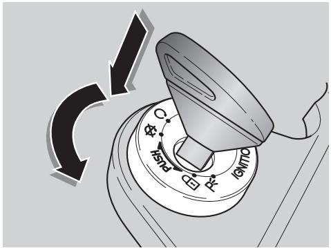
STEERING LOCK
WARNING
Never turn the key to position " 1 " when riding, or you will lose control of the vehicle.
OPERATION
To lock the steering:
Turn the handlebar fully to the left.
Turn the key to "⊗".
Press the key in and turn it to " position.
Remove the key.
| Position | Function | Key removal |
| Steering lock | The steering is locked. It is not possible to start the engine or switch on the lights. | It is possible to remove the key. The immobiliser system is activated after the key is removed (where immobiliser system is fitted). |
| X | Neither the engine, nor the lights will operate. | It is possible to remove the key. The immobiliser system is activated after the key is removed (where immobiliser system is fitted). |
| O | The engine and the lights can be operated. | It is not possible to remove the key. |
| P< | The steering is locked. It is not possible to start the engine. The parking lights of headlight and tail light are turned on. | It is possible to remove the key. The immobiliser system is activated after the key is removed (where immobiliser system is fitted). |
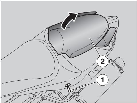
UNLOCKING/LOCKING THE PASSENGER SET/SEAT COVER
Position the vehicle on the stand, see page 56 (PLACING THE VEHICLE ON THE STAND).
Introduce the key (1) in the lock.
Turn the key (1) anticlockwise, raise the passenger seat/seat cover (2) and ease it off in a forward motion.
The tail section of the vehicle accommodates a convenient glove / tool kit compartment, simply remove passenger seat/seat cover (2).
NOTE Before lowering and locking the passenger seat/seat cover (2), make sure that you have not left the key in the glove/tool kit compartment.
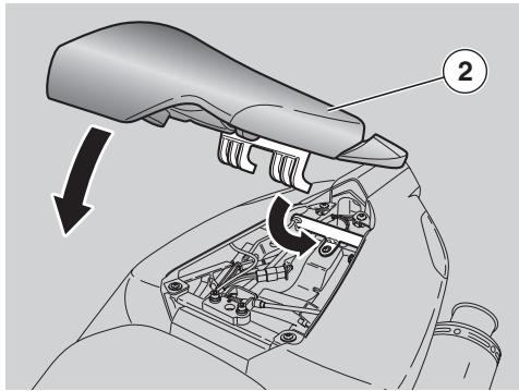
To lock the passenger seat/seat cover (2):
Slide the lower front lugs underneath the frame tube of the rear subframe.
Position passenger seat/seat cover and press down until the lock snaps shut.

WARNING
Before riding, make sure that the passenger seat/seat cover (2) is properly locked.

WARNING
Passenger seat can be replaced with seat cover, however it is not possible to carry a passenger when seat cover is on. Carrying a passenger on seat cover is illegal and the passenger is very likely to fall from the vehicle.
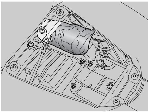
GLOVE/TOOL KIT COMPARTMENT
To reach the glove/tool kit compartment, proceed as follows:
Remove passenger seat/seat cover, see page 26 (UNLOCKING/LOCKING THE PASSENGER SET/SEAT COVER).
The tool kit (1) includes:
- 3, 4, 5, 6 mm bent Allen spanners (2);
- 11 - 13 mm double open-end spanner (3);
- 8 - 10 mm double socket spanner (4);
- 17 mm open-end spanner (5);
- 16 mm socket spanner for spark plug (6);
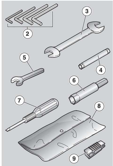
- double-ended (cross-headed/hexagon) screwdriver (7);
- tool box (8).
- fuse puller (9).
Maximum allowed weight: 1.5kg
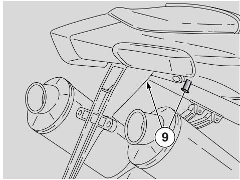
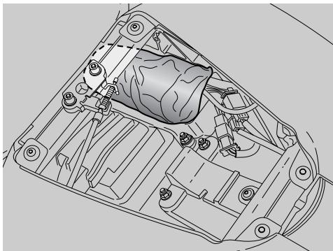
Luggage FIXING POINTS
The passenger seat can be used to carry small luggage, which must be strapped down securely to the suitable fixing points (9).
Maximum allowed weight: 9kg
WARNING
Carry small luggage only and make sure it is fastened securely.
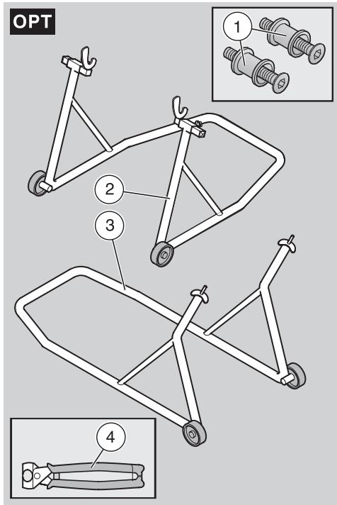
SPECIAL TOOLS OPT
To perform some specific operations, it is advisable to use the following special tools (to be requested to an aprilia Authorised Dealer):
| Tool | Operations |
| Pins (1) for rear support stand, see page 67 (FITTING THE PINS FOR THE REAR WHEEL STAND) OPT. | Positioning of the vehicle on the rear stand. |
| Rear support stand (2), see page 67 (POSITIONING THE VEHICLE ON THE REAR SUPPORT STAND) OPT. | Engine oil and engine oil filter change. Rear wheel disassembly. Drive chain adjustment. Removal of the lower fairing. |
| Front support stand (3), see page 68 (POSITIONING THE VEHICLE ON THE FRONT SUPPORT STAND) OPT. | Front wheel disassembly. |
| Click clamp (4) installation pliers, see page 61 (CLICK CLAMPS). | Click clamp installation. |
FUEL
WARNING
The fuel used in internal combustion engines is highly flammable and can become explosive under particular conditions.
It is important to refuel and service the vehicle in a well-ventilated area, with the engine off.
Do not smoke while refuelling or near fuel vapours, in any case avoid contact with naked flames, sparks and any other heat source or source of ignition to prevent fires or explosion.
Avoid spilling fuel, as it may ignite when in contact with hot engine parts.
In case some fuel has accidentally been spilt, make sure that the area has completely dried and before starting the vehicle verify that there is no fuel inside the fuel filler neck.
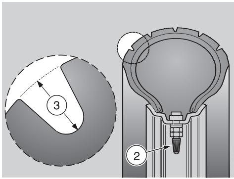
Since fuel expands under the heat of the sun and due to the effects of sun radiation, never fill the tank to the brim.
Screw the plug up carefully after refuelling. Avoid any contact of the fuel with the skin and the inhalation of vapours; do not swallow fuel or pour it from a receptacle into another by means of a tube.
DO NOT DISPOSE OF FUEL IN THE ENVIRONMENT.
KEEP AWAY FROM CHILDREN.
Use only premium-grade unleaded fuel with a minimum octane rating of 95 (RON) and 85 (MON).
To refuel, proceed as follows:
Raise the flap (1).
Insert the key (2) into the tank plug lock (3).
Turn the key clockwise, pull and open the fuel flap.
FUEL TANK CAPACITY (reserve included): 17.5 l
FUEL RESERVE: 4.5 ± 1
CAUTION
Do not add any additives or other substances to the fuel.
If you use a funnel or other similar items, make sure that they are perfectly clean.
WARNING
Do not fill the tank completely; the maximum fuel level must remain below the lower edge of the filler neck (see figure).
Refuel.
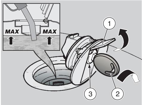
After refuelling:
NOTE The plug can only be closed when the key (2) is inserted.
Once key (2) is inserted and turned clockwise, press and close the plug.
WARNING
Make sure that the cap is properly closed.
Release the key (2) and take it out.
Close the flap (1).
BRAKE FLUID - RECOMMENDATIONS
NOTE This vehicle is provided with front and rear disc brakes, with separate hydraulic circuits.
The following information refers to a single braking system, but is valid for both.
WARNING
Sudden changes in brake lever play or a spongy feel of the lever may indicate problems with the hydraulic system. If in doubt about the braking efficiency of your bike or if you are not able to perform routine checks, contact your aprilia Authorised Dealer.
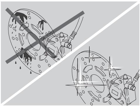
Ensure that the brake discs have not become contaminated with oil or grease, especially after maintenance or inspections.
Check that the brake lines are neither twisted nor worn out.
Prevent water or dust from accidentally getting into the circuit.
In case maintenance operations are to be performed on the hydraulic circuit, it is advisable to use latex gloves.
If the brake fluid gets in contact with the skin or the eyes, it can cause serious irritations.

WARNING
Carefully wash the parts of your body that get in contact with the fluid. Consult a doctor or an oculist if the fluid gets in contact with your eyes.
DO NOT DISPOSE OF THE FLUID IN THE ENVIRONMENT.
KEEP AWAY FROM CHILDREN.
CAUTION
When using the brake fluid, take care not to spill it on the plastic or painted parts, since it can damage them.
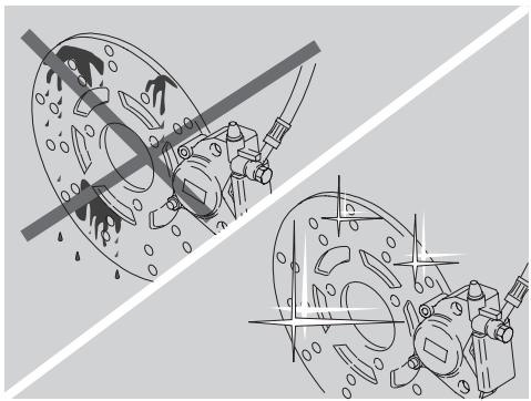
DISC BRAKES
WARNING
The brakes are the parts that most ensure your safety and for this reason they must always be perfectly working; check them before every trip.
A dirty disc will soil the pads, leading to loss of braking efficiency.
Dirty pads must be replaced, while dirty discs must be cleaned with a high-quality degreaser.
The brake fluid must be changed every two years by an aprilia Authorised Dealer.
Use brake fluid of the type specified in the lubricant chart, see page 114 (LUBRICANT CHART).
NOTE This vehicle is provided with disc brakes with two -front and rear- braking systems having separate hydraulic circuits.
The front brake is a twin-disc brake (one disc on either side of the wheel).
The rear brake uses a single disc (fitted to the right side of the wheel).
The following information refers to a single braking system, but is valid for both.
When the disc pads wear out, the level of the fluid decreases to automatically compensate for their wear.
The front brake fluid reservoir is mounted near the front brake lever coupling.
The rear brake fluid reservoir is located under right side fairing; remove the right side fairing shielding the expansion tank to find it.
NOTE Halve maintenance intervals if you are riding in rainy or dusty conditions, on rough road surfaces or when the vehicle is used in competitions.
Have the brake discs checked by an aprilia Authorised Dealer after the first 1000km (625 mi) and successively every 10000km (6250 mi).
Before departure, check the brake fluid level in the reservoirs, see page 32 (FRONT BRAKE), page 34 (REAR BRAKE), and the wear of the pads, see page 90 (CHECKING THE BRAKE PADS FOR WEAR).
Have the brake fluid changed every two years by an aprilia Authorised Dealer.
WARNING
Do not use the vehicle if the braking system leaks fluid.
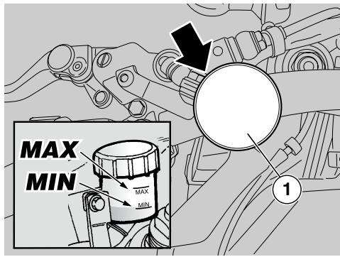
FRONT BRAKE
CHECK
Place the vehicle in vertical position and keep handlebar in the direction of travel.
Make sure that the fluid level exceeds the "MIN" mark.
MIN= minimum level
If the fluid does not reach at least the "MIN" mark:
CAUTION
When the disc pads wear out, the level of the fluid decreases progressively to compensate for their wear.
Check the brake pad wear, see page 90 (CHECKING THE BRAKE PADS FOR WEAR) and the disc wear.
If the pads and/or the disc do not need replacing, provide for topping up.
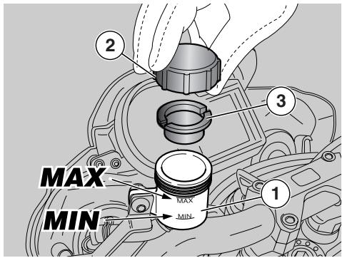
TOPPING UP
Carefully read page 30 (BRAKE FLUID - recommendations).
CAUTION
The brake fluid may flow out of the tank. Do not operate the front brake lever if the screws (1) have been loosened or, most important, with the brake fluid reservoir plug removed.
Unscrew the screws (1) of the brake fluid reservoir (2) by means of a short, cross-headed screwdriver.
CAUTION
Avoid any prolonged exposure of the brake fluid to the air.
The brake fluid is hygroscopic and when in contact with the air it absorbs its humidity.
Leave the brake fluid tank open ONLY for the time necessary for topping up.
Raise and remove the cover (3) together with the screws (1) and the gasket (4).
CAUTION
In order not to spill the brake fluid while topping up, do not shake the vehicle.
Do not put additives or other substances into the fluid.
If you use a funnel or other similar items, make sure that they are perfectly clean.
Top up the reservoir (2) by adding brake fluid, see page 114 (LUBRICANT CHART), until exceeding "MIN" level mark.
CAUTION
While topping up, never pour too much fluid.
Fill up to max. level only with new brake pads.
If topped up to max. level with worn pads, brake fluid will spill out when you change the pads at a later time.
Check the braking efficiency.
In case of excessive stroke of the brake lever or reduced efficiency of the braking system, contact an aprilia Authorised Dealer, since it may be necessary to bleed the system.
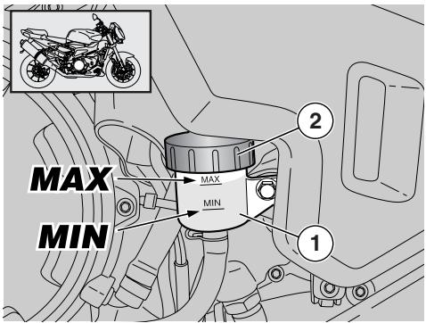
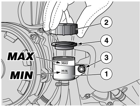
REAR BRAKE
CHECK
Keep the vehicle upright, so as to keep the fluid in the reservoir (1) level with the plug (2).
Look through the special slot in the right fairing to check that fluid level in the reservoir exceeds the "MIN" mark.
MIN= minimum level
MAX= maximum level
If the fluid does not reach at least the "MIN" mark:
CAUTION
When the disc pads wear out, the level of the fluid decreases progressively to compensate for their wear.
Check the brake pad wear, see page 90 (CHECKING THE BRAKE PADS FOR WEAR) and the disc wear.
If the pads and/or the disc do not need replacing, provide for topping up.
TOPPING UP
Carefully read page 30 (BRAKE FLUID - recommendations).
Remove the right side fairing, see page 78 (REMOVING THE SIDE FAIRINGS).
CAUTION
The brake fluid may flow out of the tank. Do not operate the rear brake lever if the brake fluid reservoir plug has been loosened or removed.
WARNING
Avoid long exposure of brake fluid to air.
The brake fluid is hygroscopic and when in contact with the air it absorbs its humidity.
WARNING
Leave the brake fluid tank open ONLY for the time necessary for topping up.
Unscrew the screw (3) completely.
Shift the complete reservoir (1) moderately outwards.
Unscrew and remove the plug (2).
CAUTION
In order not to spill the brake fluid while topping up, keep the fluid in the tank parallel to the tank rim (in horizontal position).
CAUTION
Do not add any additives or other products to the fluid.
If you use a funnel or other similar items, make sure that they are perfectly clean.
Remove the gasket (4).
Top up reservoir (1) with recommended brake fluid, see page 114 (LUBRICANT CHART), until reaching correct level that is in-between the marks "MIN" and "MAX".
CAUTION
Do not tilt reservoir (1) even if plug (2) is tightened.
This might let air in the circuit and brake system would be impaired.

CAUTION
Top up to "MAX" level only after changing the brake pads. Do not reach the "MAX" level with worn out pads, since this will cause a fluid outflow when the pads are changed.
Check the braking efficiency.
In case of excessive stroke of the brake lever or reduced efficiency of the braking system, contact an aprilia Authorised Dealer, since it may be necessary to bleed the system.
CLUTCH FLUID - RECOMMENDATIONS
NOTE This vehicle is fitted with a hydraulically-controlled clutch.
CAUTION
Any sudden changes in play or hardness in the clutch lever are warning signs of problems with the hydraulic circuit.
If in doubt about the system efficiency of your bike or if you are not able to perform routine checks, contact your aprilia Authorised Dealer.
CAUTION
Make sure the clutch hose is not twisted or worn.
Prevent water or dust from accidentally getting into the circuit.
In case maintenance operations are to be performed on the hydraulic circuit, it is advisable to use latex gloves.
Clutch fluid is an irritant. Avoid contact with eyes or skin.
In the event of accidental contact, flush affected area thoroughly. Obtain medical attention or, if fluid has been spilled in the eyes, seek the assistance of an ophthalmologist.
DO NOT DISPOSE OF THE FLUID IN THE ENVIRONMENT.
KEEP AWAY FROM CHILDREN.
When handling clutch fluid, take care not to spill it onto plastic or paintfinished parts or they will damage.
CAUTION
The clutch fluid must be changed every two years by an aprilia Authorised Dealer.
Use the fluid recommended in the lubricants table, see page 114 (LUBRICANT CHART).
The clutch fluid reservoir (1) is mounted near the clutch lever coupling.
NOTE Halve maintenance intervals if you are riding in rainy or dusty conditions, on rough road surfaces or when the vehicle is used in competitions.
Before moving off, check the reservoir level, see page 36 (CLUTCH); have the fluid changed every two years by an aprilia Authorised Dealer.
WARNING
Do not ride if the clutch hydraulic circuit is leaking.

CLUTCH
NOTE Halve maintenance intervals if you are riding in rainy or dusty conditions, on rough road surfaces or when the vehicle is used in competitions.
Have the clutch checked every 10,000 km (6250 mi) by an aprilia Authorised Dealer.
If the vehicle is used for racing:
have the clutch checked every 5000 km (3120 mi) by an aprilia Authorised Dealer.
NOTE The engine is equipped with a hydraulically-operated clutch, aided by the patented PPC (Pneumatic Power Clutch) system, which prevents rear wheel bouncing under braking.
CHECK
Place the vehicle in vertical position and keep handlebar in the direction of travel.
Make sure that the fluid level exceeds the "MIN" mark.
MIN= minimum level
MAX= maximum level
Top up if the fluid does not reach at least the "MIN" mark.
TOPPING UP
Carefully read page 35 (CLUTCH FLUID - recommendations).
CAUTION
Danger: clutch fluid could leak out. Never operate the clutch lever when the reservoir plug is loose or has been removed.

WARNING
Avoid long exposure of clutch fluid to air.
Clutch fluid is hygroscopic and will absorb moisture from the air.
Keep the clutch fluid reservoir open JUST LONG ENOUGH to top up level.
Unscrew and remove the plug (2).

CAUTION
Do not rock the motorcycle from side to side when topping up or clutch fluid will spill out.
Do not put additives or other substances into the fluid.
If you use a funnel or other similar items, make sure that they are perfectly clean.
Remove the gasket (3).
Top up reservoir (1) with recommended clutch fluid, see page 114 (LUBRICANT CHART), until reaching correct level that is in-between the marks "MIN" and "MAX".

CAUTION
Never exceed the "MAX" level.
Check the clutch for proper operation. When the clutch lever has exceeding travel or if you notice a loss of efficiency, contact an aprilia Authorised Dealer. The clutch hydraulic circuit may need bleeding.

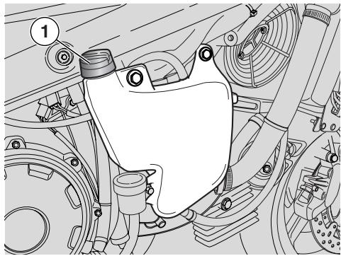
COOLANT

CAUTION
Do not ride when coolant is below the minimum level (LOW).
NOTE You will need to remove the right side fairing in order to top up coolant level.
NOTE Halve maintenance intervals if you are riding in rainy or dusty conditions, on rough road surfaces or when the vehicle is used in competitions.
Before departure, check the coolant level, see page 39 (CHECKING AND TOPPING UP); have the coolant changed every two years: for this operation, contact an aprilia Authorised Dealer.

WARNING
Coolant is toxic when ingested. Contact with eyes or skin may cause irritation.
In the event of contact with eyes or skin, rinse repeatedly with abundant water and seek medical advice. In the event of ingestion, induce vomiting, rinse mouth and throat with abundant water and seek medical advice immediately.
KEEP AWAY FROM CHILDREN.
DO NOT DISPOSE OF THE FLUID IN THE ENVIRONMENT.
Be careful not to spill the coolant on the red-hot parts of the engine: it may catch fire and send out invisible flames.
In case any maintenance operation should be required, it is advisable to use latex gloves.
CAUTION
Have the pads changed by your aprilia Authorised Dealer.
The coolant is composed of 50% water and 50% antifreeze.
This mixture is ideal for most operating temperatures and ensures good protection against corrosion.
It is advisable to keep the same mixture also in the hot season, since in this way losses due to evaporation are reduced and it is not necessary to top up very frequently.
The mineral salt deposits left in the radiator by evaporated water are thus reduced and the efficiency of the cooling system remains unchanged.
If the outdoor temperature is below 0^ , check the cooling circuit frequently and if necessary increase the antifreeze concentration (up to maximum 60% ).
For the cooling solution use distilled water, in order not to damage the engine.
WARNING
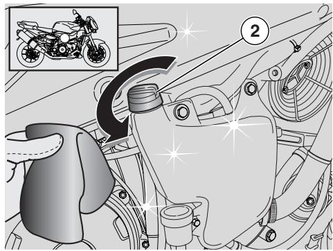
Do not remove the expansion tank plug (1) when the engine is hot, since the coolant is under pressure and its temperature is high.
If it gets in contact with the skin or with clothes it may cause severe burns and/or damage.
CHECKING AND TOPPING UP
WARNING
Check the coolant level and top up the expansion tank with cold engine.
Stop the engine and wait until it has cooled down.
Keep the vehicle in vertical position, with the two wheels resting on the ground.
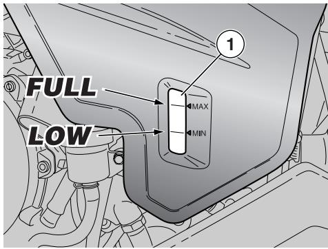
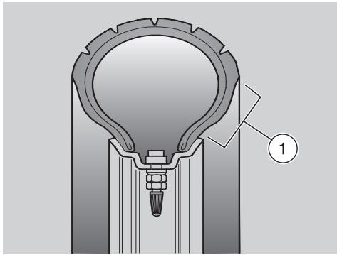
Look through the slot (2) in the right fairing and check that coolant level in the expansion tank is between the "FULL" e "LOW" marks.
FULL= maximum level
LOW= minimum level
If not, proceed as follows:
Remove the side fairing, see page 78 (REMOVING THE SIDE FAIRINGS).
Unscrew and remove the filling cap (1).
WARNING
Coolant is toxic when ingested. Contact with eyes or skin may cause irritation.
Do not use your fingers or any other object to check if there is enough coolant.
CAUTION
Do not put additives or other substances into the fluid.
If you use a funnel or other similar items, make sure that they are perfectly clean.

Top up the expansion tank by adding coolant, see page 114 (LUBRICANT CHART), until this almost reaches the "FULL" level. Do not exceed this level, otherwise the fluid will flow out while the engine is running.
Put back the filling cap (1).
CAUTION
In case of excessive consumption of coolant and in case the tank remains empty, make sure that there are no leaks in the circuit. Have it repaired by an aprilia Authorised Dealer.
TYRES
This vehicle is equipped with tubeless tyres.
NOTE Halve maintenance intervals if you are riding in rainy or dusty conditions, on rough road surfaces or when the vehicle is used in competitions.

WARNING
Check the inflation pressure at room temperature every two weeks.
Check the tyre condition and inflation pressure at room temperature after the first 1000km (625 mi) and every two weeks afterwards, see page 110 (TECHNICAL DATA).
Measuring pressure on hot tyres will lead to inaccurate measurement.
Carry out the measurement especially before and after long rides.
If the inflation pressure is too high, the ground unevenness cannot be dampened and is therefore transmitted to the handlebar, thus compromising the driving comfort and reducing the road holding during turns.
If, on the contrary, the inflation pressure is too low, the tyre sides (1) are under greater stress and the tyre itself may slip on the rim or it may become loose, with consequent loss of control of the vehicle.
In case of sudden braking the tyres could even come off the rims.
Further, the vehicle could skid while turning.

WARNING
Check the surface and the wear of the tyres, since tyres in bad conditions can impair both the grip and the vehicle handling.
Some of the tyres approved for this vehicle are equipped with wear indicators.
There are several kinds of wear indicators. For more information on how to check the tyres for wear, contact your Dealer.
Visually inspect the tyres for wear and have them changed if worn.
Change the tyre when it is worn out or in case of puncture on the tread side, if the puncture is larger than 5mm
After repairing a tyre, have the wheels balanced.

WARNING
The tyres must be replaced with other tyres of the type and model recommended by the manufacturer, see page 110 (TECHNICAL DATA); the use of tyres different from those prescribed may adversely affect the manoeuvrability of the vehicle.
Do not install tyres with air tube on rims for tubeless tyres and vice versa.
Make sure that the inflation valves (2) always have their sealing caps on, to prevent the tyres from suddenly going flat.
Tyre replacement and repair, and wheel servicing and balancing are delicate operations that should be carried out using adequate tools and are best left to experienced mechanics.
For this reason, it is advisable to have the above mentioned operations carried out by an aprilia Authorised Dealer or by a qualified tyre repairer.
If the tyres are new, they may still be covered with a slippery film: ride carefully for the first miles. Do not oil the tyres with unsuitable fluids. Old tyres, even if not completely worn down, may become hard and provide poor grip.
In this case, replace them.
MINIMUM TREAD DEPTH LIMIT (3):
front and rear 2mm ("USA" 3 mm), anyway not less than required by the regulations in force in the country where the vehicle is used.
ENGINE OIL
WARNING
Prolonged or repeated contact with engine oil may cause severe skin damage.
Wash your hands carefully after use.
KEEP AWAY FROM CHILDREN.
DO NOT DISPOSE OF THE OIL IN THE ENVIRONMENT.
Dispose of engine oil - stored in a sealed container - through the nearest waste oil reclamation firm or through the supplier.
In case any maintenance operation should be required, it is advisable to use latex gloves.
CAUTION
If the light "△" comes on during regular engine operation and on the same time even the symbol "♀" is on, it means that the engine oil pressure in the circuit is low.
In this case, check the engine oil level, see page 62 (CHECKING AND TOPPING UP ENGINE OIL LEVEL); if the level is not correct, stop the engine immediately and contact an aprilia Authorised Dealer.
CAUTION
Proceed with care.
Do not spill the oil!
Take care not to smear any component, the area in which you are working and the surrounding area. Remove any trace of oil.
In case of leakage or malfunctions, contact an aprilia Authorised Dealer.
Periodically check the engine oil level, see page 62 (CHECKING AND TOPPING UP ENGINE OIL LEVEL).
To change engine oil, see page 59 (REGULAR SERVICE INTERVALS CHART) and page 62 (CHECKING AND TOPPING UP ENGINE OIL LEVEL).
NOTE Use high-quality 15W - 50 oil, see page 114 (LUBRICANT CHART).
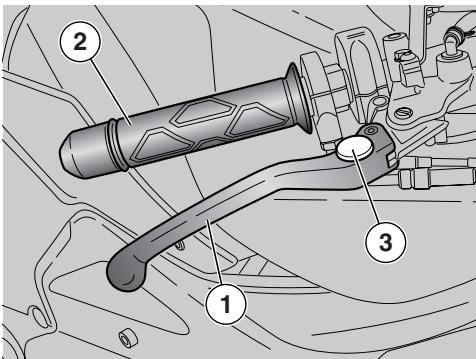
The grab distance of the lever (1) [distance from the grip (2)] can be adjusted by rotating the adjuster (3).
The MAX and MIN click settings give a grab distance of 126 and 83mm respectively.
★Push the lever (1) forward and rotate the adjuster (3) until setting the lever (1) at the desired distance.
The brake control lever is positioned ergonomically during the assembly of the vehicle.
If necessary, it is possible to adjust the brake control lever clearance:
Slacken the lock nut (4).
Unscrew the master cylinder actuating rod (5) to ensure a minimum clearance of 0.5 - 1 mm between the rod and the piston.
CAUTION
Make sure that the lever (6) has a certain amount of free play, or the brake will remain applied leading to early wear of braking elements.
Lever (6) idle stroke: 4 mm (measured at the lever end).
Lock the master cylinder actuating rod (5) by means of the lock nut (4).
CAUTION
After the adjustment, make sure that the wheel rotates freely with released brake.
Check the braking efficiency.
If necessary, contact your aprilia Authorised Dealer.
The position of the control levers is determined based on ergonomic principles at the factory.
If necessary, it is possible to adjust the position of the levers.
Position the vehicle on the stand, see page 56 (PLACING THE VEHICLE ON THE STAND).
Partially unscrew the screw (1).
Rotate the eccentric (2) until finding the optimal position for the pedal (3).
Tighten the screw (1) and make sure that the eccentric retains its position.
CAUTION
If the gear change lever needs further adjustment, contact an aprilia Authorised Dealer.
EXHAUST MUFFLER/EXHAUST SILENCER
WARNING
Tampering with the noise control system is prohibited.
Owners are warned that the law may prohibit:
- the removal or rendering inoperative by any person, other than for purposes of maintenance, repair or replacement, of any device or element of design incorporated into any new vehicle – for the purpose of noise control – prior to its sale or delivery to the ultimate purchaser or while it is in use;
- the use of the vehicle after such device or element of design has been removed or rendered inoperative by any person.
Check the exhaust silencer and the silencer pipes, making sure that there are neither signs of rust, nor holes and that the exhaust system works effectively.
If the noise produced by the exhaust system increases, immediately contact your aprilia Authorised Dealer.
WARNING
Both exhaust silencers are equipped with catalytic converter and become very hot to the touch. Be careful! Danger of burns!
INSTRUCTIONS FOR USE
GETTING ON AND OFF THE VEHICLE
The instructions below must be followed with the maximum care in order to avoid any injury to persons and damage to property and to the vehicle, caused by the falling of the rider or the passenger from the vehicle and/or the falling or overturning of the vehicle itself.
WARNING
Risk of falling and overturning. Proceed with care.
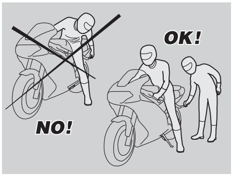
When getting on and off the vehicle, make sure nothing can impair your movements. Also, your hands should be free (replace any objects, such as your helmet, gloves or dangling glasses before mounting or dismounting). Get on and off the vehicle only from the left side and always with extended side stand.
CAUTION
Do not apply the load of your weight or of the passenger's weight onto the side stand.
The stand has been designed to support the weight of the vehicle and a minimum load, without the rider and the passenger.
The purpose of placing the vehicle on the side stand before mounting is to keep the vehicle from falling or overturning. This does not mean that the side stand should be used to support the weight of rider and passenger.
While getting on and off, the weight of the vehicle may make you lose balance, and the vehicle may fall or overturn.

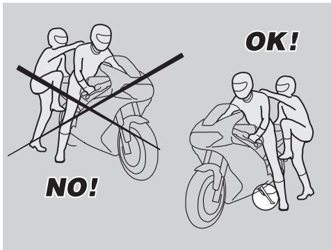
NOTE The rider must always be the first person to get on the vehicle and the last to get off and it is the rider who controls the balance and stability of the vehicle when the passenger gets on and off.
When getting on and off the vehicle, the passenger must make careful movements, in order to maintain the balance of the vehicle and the rider.
NOTE The rider is responsible for instructing the passenger on how to safely get on and off the vehicle.
The vehicle is equipped with special passenger footrests to make it easier to get on and off the vehicle. The passenger must always use the left footrest to get on and off the vehicle.
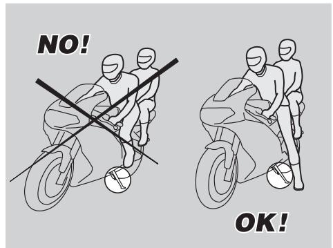
Neither get off, nor try to get off the vehicle by jumping or stretching your leg down to the ground. In both cases this would compromise the stability and balance of the vehicle.
NOTE Bags or objects strapped to the rear of the vehicle can represent an obstacle while getting on and off.
In any case, perform a controlled movement with your right leg, which must avoid striking and safely pass the rear part of the fairing or the luggage without creating unbalance.
GETTING ON THE VEHICLE
Grasp the handlebar correctly and get on the vehicle without loading your weight onto the side stand.
NOTE If it is impossible for you to place both feet on the ground, place the right foot on the ground (in case of unbalance, the left side of the vehicle is prevented from falling over by the side stand) and keep the left foot ready to rest on the ground.
Place both feet on the ground and straighten the vehicle into riding position while keeping it in balance.
NOTE The rider must not extract or attempt to extract the passenger footrest while seated astride the vehicle, because this might compromise the stability and balance of the vehicle.
Have the passenger extract the two passenger footrests.
Instruct the passenger on how to safely get on the vehicle.
Kick the side stand completely back using your left foot.
GETTING OFF THE VEHICLE
Choose a suitable parking area, see page 55 (PARKING).
Stop the vehicle, see page 54 (STOPPING).
WARNING
Make sure that the parking surface is free from obstacles, firm and flat.
With the left shoe heel, extend the side stand completely by acting on the appropriate lever.
NOTE If it is impossible for you to place both feet on the ground, place the right foot on the ground (in case of unbalance, the left side of the vehicle is prevented from falling over by the side stand) and keep the left foot ready to rest on the ground.
Place both feet on the ground, keeping the vehicle in balance in riding position.
Instruct the passenger how to safely get off the vehicle.
CAUTION
Risk of falling and overturning.
Make sure that the passenger has dismounted.
Do not load your weight onto the side stand.
Incline the vehicle until the stand rests on the ground.
Grasp the handlebar correctly and get off the vehicle.
Rotate the handlebar completely leftwards.
Lift the passenger footrests.
CAUTION
Make sure that the vehicle is stable.


CAUTION
After covering the first 1000km (625 mi) and every 10,000 km (6250 mi) afterwards, the "SERVICE" warning (2) appears on the right display.
In this case have an aprilia Authorised Dealer perform all service operations as indicated in the scheduled maintenance chart, see page 59 (REGULAR SERVICE INTERVALS CHART).
PRE-RIDE CHECKS
WARNING
Before starting, always perform vehicle pre-ride checks, to ensure safe operation see page 47 (PRE-RIDE CHECKS CHART).
Failure to comply with these checking operations can cause severe personal injuries or damages to the vehicle.
Do not hesitate to consult your aprilia Authorised Dealer in case there is something you do not understand about the operation of some controls or in case you suspect or discover some failures.
It does not take long to carry out a check-up and this operation ensures you much more safety.
NOTE This vehicle is equipped with an electronic engine control unit capable of detecting abnormal operation in real time and storing faults.
Each time the ignition key is set to , the word “ SERVICE” (1) appears on the right side of the multifunction display for approximately three seconds.
CAUTION
If the wording "△ SERVICE" (1) is displayed during normal engine operation, it means that the Engine Control Unit has detected a fault. In many cases the engine keeps running with limited performance; contact an aprilia Authorised Dealer immediately.
PRE-RIDE CHECKS CHART
| Component | Check | Page |
| Front and rear disc brakes | Check the operation, the idle stroke of the control levers, the fluid level and make sure there are no leaks.Check the wear of the pads.If necessary, top up the fluid tank. | 30, 31, 32, 34, 90 |
| Throttle | Make sure that it works smoothly and that it is possible to open and close it completely, in all steering positions. Adjust and/or lubricate, if necessary. | 91 |
| Engine oil | Check and/or top up if necessary. | 41, 62 |
| Wheels / tyres | Check the tyre surface, the inflation pressure, wear and tear and any damage.Remove any foreign matter that may be stuck in the tread grooves. | 40 |
| Brake levers | Make sure that they work smoothly.Lubricate the articulations and adjust the stroke if necessary. | 43 |
| Clutch | Check for proper operation, check clutch lever free play, clutch fluid level and check for leaks.If necessary, top up the fluid; the clutch must work without snatching and/or slipping. | 35, 36 |
| Steering | Make sure that the steering rotates smoothly, without any clearance or looseness. | - |
| Side stand | Make sure that it operates correctly. Make sure that when the stand is let up or down there is no friction and that the spring tension brings it back to its normal position.If necessary, lubricate joints and articulations.Make sure that the safety switch operates correctly. | 94, 99 |
| Fastening elements | Make sure that the fastening elements are not loose. If necessary, adjust or tighten them. | - |
| Drive chain | Check the slack. | 75 |
| Fuel tank | Check the fuel level and top up, if necessary.Check the circuit for leaks.Make sure that the fuel cap is correctly closed. | 29, 77 |
| Coolant | The coolant level in the expansion tank must be included between the “FULL” and “LOW” marks. | 37, 37 |
| Engine stop switch(■○-■○) | Make sure that it operates correctly. | 22 |
| Lights, warning lights, horn, rear brake light switches and electrical devices | Check horn and indicators for proper operation. Change bulbs or fix a failure, if necessary. | 99 - 103 |
STARTING
This is a high-performance vehicle. We recommend that you become familiar with it gradually using the greatest care.
Do not position any object inside the front fairing (between the handlebar and the instrument panel), in order not to hinder the rotation of the handlebar and visibility toward the instrument panel.
NOTE Before starting the engine, carefully read chapter "safe drive", see page 5 (SAFE DRIVE).
WARNING
Exhaust emissions contain carbon oxide, which is a poisonous gas and extremely harmful if inhaled.
Avoid starting the engine in closed or badly-ventilated rooms.
CAUTION
Failure to heed this warning may cause loss of consciousness or even lead to death by asphyxia.
NOTE With the side stand down, the engine can be started only if the gearbox is in neutral; in this case, if you try to engage the gears, the engine stops.
With the side stand up, it is possible to start the engine either in neutral gear or with engaged gears and pulled in clutch lever.
Get on the vehicle in riding position, see page 44 (INSTRUCTIONS FOR USE).
Make sure that the stand is completely up.
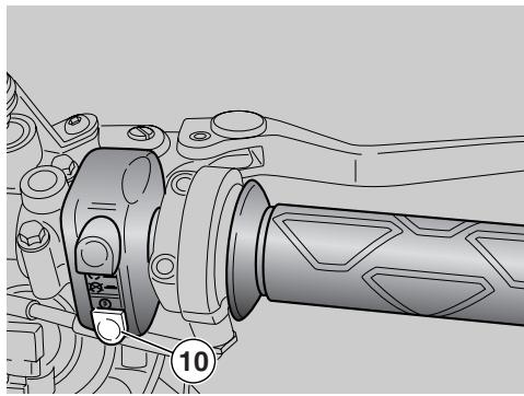
Make sure that the dimmer switch (1) is in position 口 .
Set the engine stop switch (2) to position "O".
Turn the key (3) and set the ignition switch to position
What should happen now is:
- starting page is shown for 2 seconds on multifunction display.
- All warning lights (4) on the instrument panel and the backlighting come on for 2 seconds.
- The odometer pointer (5) points the last red line threshold setting for 3 seconds and then returns to idle rpm.
- During normal operation, all instruments will give the current reading.
CAUTION
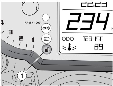
If the low fuel warning light "B" (6) on the instrument panel comes on, provide for topping up as soon as possible, see page 29 (FUEL).
NOTE The units of measurement of speedometer (km or mi) and coolant temperature (^ or F^ ), the red line threshold, clock functions and lap timer are user-selectable. See page 16 (MULTIFUNCTION COMPUTER)
WARNING
On a new vehicle the red line threshold is set at 6000 rpm. Increase the threshold gradually as you become familiar with your vehicle.
During running-in, never exceed the recommended rpm, see page 54 (RUNNING-IN).
Operate a brake to lock at least one wheel.
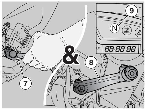
Pull the clutch lever (7) completely and shift the gearbox lever (8) into neutral [green warning light “N” (9) on].
The vehicle is equipped with a cold start feature controlled by the ECU which
operates automatically when starting the engine from cold.
CAUTION
To avoid excessive current draw from the battery, do not hold down the starter button " () for more than fifteen seconds.
If the engine does not start within fifteen seconds, wait ten seconds before operating the starter button " 日 " again.
Press the starter button " 日 " (10)-do not open the throttle yet-and release the button as soon as the engine starts.
CAUTION
Avoid pressing the starter button "②" (10) when the engine is running, or the starter motor may damage.
If the engine oil pressure symbol " " is displayed, it means that engine oil pressure in the circuit is low.
In this case, stop the engine immediately and contact an aprilia Authorised Dealer.
Keep at least one brake lever pulled and do not accelerate until you start.
CAUTION
Never leave abruptly with cold engine. To reduce the emission of polluting substances and the consumption of fuel, warm the engine up by proceeding at low speed for the first miles.
CAUTION
If the wording "△ SERVICE" is displayed during normal engine operation, it means that the Engine Control Unit has detected a fault.
CAUTION
In many cases the engine keeps running with limited performance; contact an aprilia Authorised Dealer immediately.

MOVING OFF - RIDING
WARNING
The vehicle's engine delivers considerable power. Familiarise with the vehicle gradually and use the greatest care.
Do not position any object inside the front fairing (between the handlebar and the instrument panel), in order not to hinder the rotation of the handlebar and visibility toward the instrument panel.
NOTE Before moving off, carefully read the "safe drive" chapter, see page 5 (SAFE DRIVE).

CAUTION
If the low fuel light "R" (1) on the instrument panel comes on while vehicle is running, it means that you still have 4,5 ± 1 of fuel in the tank. Provide for topping up as soon as possible, see page 29 (FUEL).

WARNING
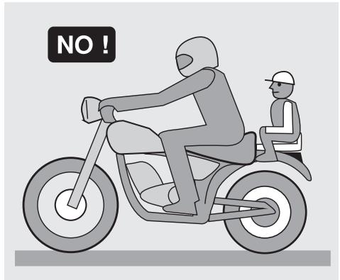
If you ride without passenger, make sure that the passenger footrests are folded.

CAUTION
While riding, keep your hands on the grips and your feet on the footrests. NEVER RIDE IN ANY POSITION OTHER THAN THOSE INDICATED.

WARNING
If you ride with a passenger, instruct him/her so that he/she does not create problems during manoeuvres.
Before leaving, make sure that the stand is completely up.
To leave:
Start the engine, see page 48 (STARTING).
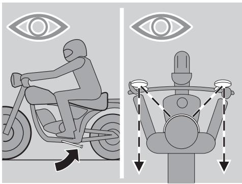
Adjust the inclination of the rear-view mirrors correctly.

CAUTION
With the vehicle at rest, try to get acquainted with the use of the rear-view mirrors. The reflecting surface is convex, therefore the objects seem to be farther away than they actually are. These mirrors offer a "wide-angle" view. It may take some time to learn to accurately judge the distance of traffic behind.
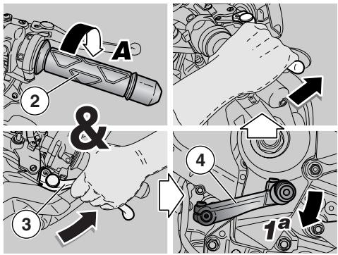
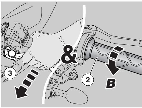
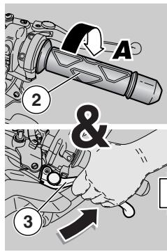
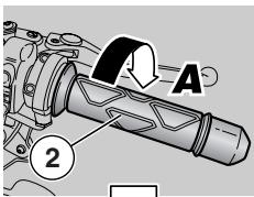
With released throttle grip (2) (Pos.A) and engine idling, pull the clutch lever (3) completely.
Engage the first gear, by pushing the gear lever (4) downwards.
Release the brake lever (pulled on the starting).
WARNING
Release the clutch lever smoothly, or you may stall the engine or cause the vehicle to jerk forwards.
Never accelerate abruptly or excessively when releasing the clutch lever, in order to prevent the clutch from "slipping" (slow release) or the front wheel from raising "rearing up" (quick release).
Slowly release the clutch lever (3) and at the same time accelerate by slightly turning the throttle grip (2) (Pos.B).
The vehicle will start moving.
Ride at reduced speed for the first miles, in order to warm the engine up.
CAUTION
Never exceed the recommended rpm, see page 54 (RUNNING-IN).
Increase the speed by gradually rotating the throttle grip (2) (Pos.B), without exceeding the recommended rpm, see page 54 (RUNNING-IN).
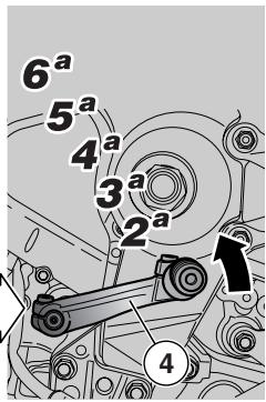
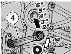
To engage the second gear:
CAUTION
Proceed quickly. Never ride the vehicle at too low rpm.
Release the throttle grip (2) (Pos.A), pull the clutch lever (3) and lift the gear shift lever (4). Release the clutch lever (3) and accelerate.
Repeat the last two operations and shift up.
CAUTION
If the engine oil pressure logo "comes on during regular engine operation, it means that engine oil pressure in the circuit is low.
In this case, stop the engine immediately and contact an aprilia Authorised Dealer.
The downshifting should be carried out in the following situations:
When riding downhill or when braking, in order to increase the braking action by using the compression of the engine.
When riding uphill, if the gear engaged is not suitable to the speed (high gear, moderate speed) and the engine rpm decreases.
CAUTION
Shift the gears one by one; the simultaneous downshifting of more than one gear may make you exceed the maximum rpm (redline).
Before and during the downshifting, release the throttle grip and decelerate, in order to avoid the "redline".
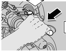
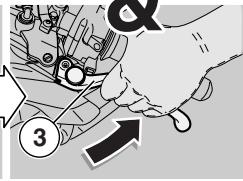
To shift down, proceed as follows:
Release the throttle grip (2) (Pos.A).
If necessary, pull the brake levers moderately and decrease the speed of the vehicle.
Pull the clutch lever (3) and lower the gear shift lever (4) to shift down.
If the brake levers are pulled, release them.
Release the clutch lever and accelerate moderately.
CAUTION
If the coolant temperature readout of the multifunction display is between 115^ (239^) and 135^ (275^) , see page 16 (MULTIFUNCTION COMPUTER), stop the vehicle and let the engine run at 3000 rpm for approximately two minutes to keep coolant circulating in the system; position the engine stop switch on "■" and check the coolant level, see page 37 (COOLANT).
If coolant temperature readout is still flashing after you have checked level, contact an aprilia Authorised Dealer.
Do not set the ignition switch to "×", as this would switch off the cooling fans regardless of coolant temperature and temperature would keep rising.
If the wording "△ SERVICE" is displayed on the right side during normal engine operation, it means that the Engine Control Unit has detected a fault.
In many cases the engine keeps running with limited performance; contact an aprilia Authorised Dealer immediately.
To avoid the overheating of the clutch, keep the engine running with vehicle at rest, engaged gears and pulled clutch lever for the shortest time possible.
WARNING
Avoid opening and closing the throttle repeatedly and continuously, so that you do not accidentally lose control of the vehicle. If you have to brake, close the throttle and put on both brakes in order to obtain uniform deceleration, properly exerting pressure on the braking parts.
Using one brake only reduces braking force significantly and may lock a wheel resulting in loss of grip.
If you stop uphill, decelerate completely and use the brakes only to keep the vehicle steady.
The use of the engine to keep the vehicle steady may cause the overheating of the clutch.
When approaching a bend, slow down or brake in good time. Take the bend at moderate, steady speed or accelerate slightly. Late braking may put the vehicle into a skid.
If the brakes are operated continuously on downhill stretches, the friction surfaces may overheat, thus reducing the braking efficiency. Exploit the engine compression and shift down by putting on both brakes intermittently.
Never ride downhill with the engine off!
When visibility is insufficient, switch on the low beam even during the day, in order to make your vehicle more visible. In case of wet ground or scarce wheel grip (snow, ice, mud, etc.), ride slowly, avoiding sudden braking or manoeuvres that could make you lose grip and fall down.
WARNING
Pay the utmost attention to any obstacle or variation of the ground.
Uneven road surfaces, rails, inspection covers, painted signals, construction site metal covers become slippery in rainy weather and must be negotiated carefully, smoothly and keeping the vehicle upright.
Always signal your intention to change lanes or direction in good time using the direction indicators. Avoid sudden manoeuvres.
Switch off the direction indicators immediately after changing direction.
Be very careful when overtaking or being overtaken.
When it rains, large vehicles lift surface water, which affects visibility. In addition, the slip stream may make you lose control of the vehicle.
RUNNING-IN
The running-in of the engine is essential to ensure its life and correct operation.
If possible, ride on hilly roads and/or roads with many bends, so that the engine, the suspensions and the brakes undergo a more effective running-in.
During running-in, change speed.
In this way the components are first "loaded" and then "relieved" and the engine parts can thus cool down.
Even if it is important to stress the engine components during running-in, take care not to exceed.
NOTE Top performance is only obtained after covering the first 1500km (937 mi).
Keep to the following indications:
Do not open the throttle completely if the speed is low, both during and after running-in.
Until you have covered the first 100~km (62 mi), use the brakes gently and avoid hard, prolonged braking. This ensures a correct bedding-in of the pads on the brake disc.
During the first 1000 km (625 mi) never exceed 6000 rpm.
WARNING
After the first 1000 km (625 mi), have an aprilia Authorised Dealer carry out the checks indicated in the column "After running-in" of the regular service intervals chart, see page 59 (REGULAR SERVICE INTERVALS CHART), in order to avoid hurting yourself or other people and/or damaging the vehicle.
Between the first 1000 (625 mi) and 1500~km (937 mi) ride more briskly, change speed and use the maximum acceleration only for a few seconds, in order to ensure better coupling of the components; never exceed 7500 rpm (see table).
After the first 1500~km (937 mi), you can expect higher performance from your engine. However, never exceed the maximum rpm allowed (11,000 rpm).
| Engine maximum rpm recommended | |
| Mileage km (mi) | rpm |
| 0 – 1000 (0 – 625) | 6000 |
| 1000 – 1500 (625 – 937) | 7500 |
| over 1500 (937) | 11000 |
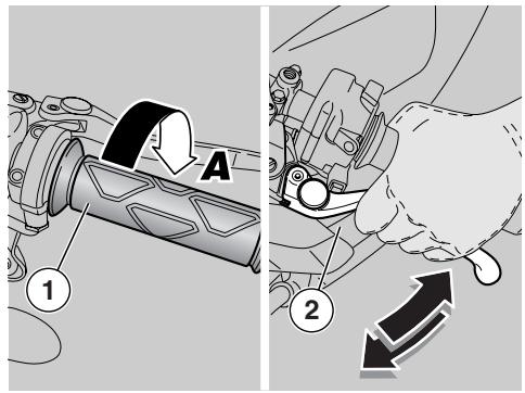
STOPPING
WARNING
If possible, avoid stopping abruptly, slowing down suddenly and limit braking.
Release the throttle grip (1) (Pos.A), gradually put on the brakes and at the same time shift down in order to decrease the speed, see page 50 (MOVING OFF - RIDING).
Once the speed has decreased, before stopping the vehicle:
Pull the clutch lever (2) in order to prevent the engine from stalling.
When the vehicle has come to rest:
Select neutral (green warning light " N" on).
Release the clutch lever (2).
In case of a brief stop, keep at least one brake on.
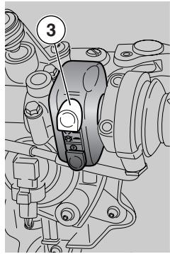
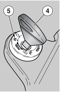
PARKING
It is very important to choose a suitable parking area, respecting the road signs and the indications given below.
WARNING
Park the vehicle on firm and level ground to prevent it falling over.
Neither lean the vehicle against walls, nor lay it on the ground.
Make sure that the vehicle and especially its red-hot parts do not represent a danger for persons and children. Do not leave the vehicle unattended when the engine is on or the key is inserted into the ignition switch.
Stay away from the cooling fans even when they are not operating. They might switch on unexpectedly and your clothing or hair might be caught in the fans.
WARNING
The fall or excessive inclination of the vehicle may cause the fuel to flow out of the tank.
The fuel used for internal combustion engines is extremely inflammable and in particular conditions it can become explosive.
WARNING
Do not apply the load of your weight or of the passenger's weight onto the side stand.
To park the vehicle:
Choose a suitable parking area.
Stop the vehicle, see page 54 (STOPPING).
Set the engine stop switch (3) to position
Turn the key (4) and set the ignition switch (5) to position "X".
WARNING
When getting on or off the vehicle, keep to the instructions given, see page 44 (GETTING ON AND OFF THE VEHICLE).
Following the indications, wait until the passenger has got off the vehicle before dismounting.
Lock the steering, see page 25 (STEERING LOCK) and remove the key (4).
WARNING
Make sure that the vehicle is stable.

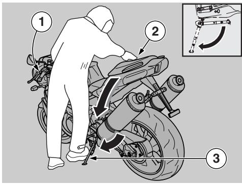
PLACING THE VEHICLE ON THE STAND
SIDE STAND
To place the vehicle on the side stand while seated astride the vehicle, see page 44 (INSTRUCTIONS FOR USE). If any manoeuvre (for example, moving the vehicle) required the lifting of the stand, to place the vehicle on the stand again, proceed as follows:
WARNING
Make sure that the parking surface is free from obstacles, firm and flat.
Choose a suitable parking area, see page 55 (PARKING).
Grasp the left grip (1) and place your right hand on the rear upper part of the vehicle (2).
Press the side stand with your right foot and extend it completely (3).
Incline the vehicle until the stand rests on the ground.
Steer the handlebar completely leftwards.
WARNING
Make sure that the vehicle is stable.
SUGGESTIONS TO PREVENT THEFT
CAUTION
Do not use any "brake lock" devices. Failure to heed this warning can seriously damage the braking system and lead to an accident thus provoking serious injuries or death.
NEVER leave the key in the ignition switch and always use the steering lock.
Park the vehicle in a safe place, possibly in a garage or a protected place.
When possible, use an additional antitheft device.
Make sure that all documents are in order and the road tax has been paid.
Write down your personal data and telephone number in this page, to facilitate the identification of the owner in case of finding after theft.
SURNAME:
NAME:
ADDRESS:
TELEPHONE NO.:
NOTE Very often stolen vehicles are identified thanks to the data written in the use/maintenance manual.
IMMOBILISER (if fitted)
The vehicle is fitted with an immobiliser antitheft system by that is automatically activated each time the ignition key is removed from the switch.
Store the spare key in a safe place. Immobiliser system keys cannot be duplicated. If both keys are lost, you will have to have a number of vehicle components replaced (rather than just the key-operated locks).
Embedded in the key grip is a transponder, an electronic device that modulates the radiofrequency signal emitted by a special antenna built into the switch when the key is turned to on. The modulated signal acts as a "password" that tells the control unit whether an authorised key is being used to start the engine.
NOTE The immobiliser system supports up to four enabled keys.
New keys can only be enabled at your Authorised dealer, who has the master key available.
The programming procedure wipes off all existing key codes. An owner who wishes to have a new key enabled, will have to bring all the keys he intends to be using to the Dealer.
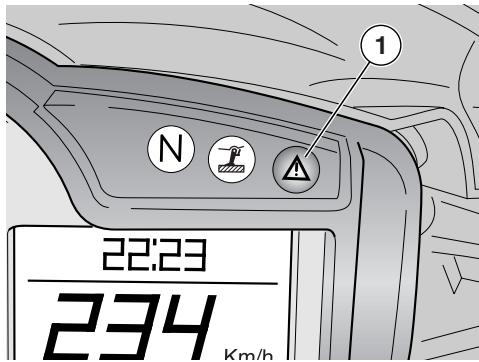
Immobiliser status is indicated by a light (1) on the instrument panel:
-Immobiliser off - light off
-Immobiliser on - light blinking
-Key not recognised - quick blinking
MAINTENANCE
WARNING
Risk of fire.
Keep fuel and other flammable substances away from the electrical components.
Before beginning any maintenance operation or any inspection of the vehicle, stop the engine, extract the key from the ignition switch, wait until the engine and the exhaust system have cooled down and if possible lift the vehicle by means of the proper equipment, on firm and flat ground.
Before proceeding, make sure that the room in which you are working is properly ventilated.
Keep away from the red-hot parts of the engine and of the exhaust system, in order to avoid burns.
Do not hold any mechanical piece or other parts of the vehicle with your mouth: the components are not edible and some of them are harmful or even toxic.
CAUTION
If not expressly indicated otherwise, for the reassembly of the units repeat the disassembly operations in reverse order.
In case any maintenance operation should be required, it is advisable to use latex gloves.
Routine maintenance operations can usually be carried out by the user, but sometimes specific tools and specific technical skills may be required.
In case periodic maintenance operations, assistance or technical advice are needed, contact an aprilia Authorised Dealer, who will ensure you prompt and accurate servicing.
Ask your aprilia Authorised Dealer to test the vehicle on the road after a repair or periodic maintenance operation.
In any case, personally carry out the "Preliminary checking operations" after any maintenance operation, see page 47 (PRE-RIDE CHECKS CHART).
NOTE This vehicle is equipped with an electronic engine control unit capable of detecting abnormal operation in real time and storing faults.
Each time the ignition key is set to "O", the word "△ SERVICE" (1) appears on the right side of the multifunction display for approximately three seconds.
CAUTION
If the wording "△ SERVICE" is displayed during normal engine operation, it means that the Engine Control Unit has detected a fault.
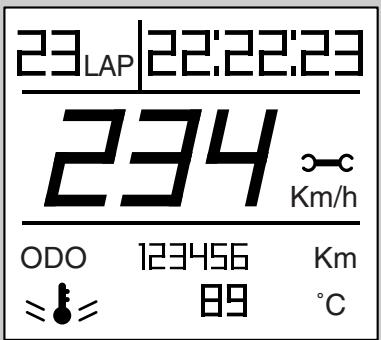
In many cases the engine keeps running with limited performance; contact an aprilia Authorised Dealer immediately.
CAUTION
After covering the first 1000km (625 mi) and every 10000 km (6250 mi) afterwards, the " SERVICE" (1) symbol appears on the right display.
In this case have an aprilia Authorised Dealer perform all service operations as indicated in the scheduled maintenance chart, see page 59 (REGULAR SERVICE INTERVALS CHART).
REGULAR SERVICE INTERVALS CHART
OPERATIONS TO BE CARRIED OUT BY THE aprilia Authorised Dealer (WHICH CAN BE CARRIED OUT EVEN BY THE USER).
Key
① = check and clean, adjust, lubricate or change, if necessary;
② = clean;
③ = change;
④ = adjust.
NOTE Halve maintenance intervals if you are riding in rainy or dusty conditions, on rough road surfaces or when the vehicle is used in competitions.
(^*) = Check every two weeks or at the specified intervals.
| Component | After running-in [1000 km (625 mi)] | Every 5000 km (3125 mi) (only for racing use | Every 10000 km (6250 mi) or 12 months | Every 20000 km (12500 mi) or 24 months |
| Spark plug | ③ | ① | ③ | |
| Air filter | ③ | ① | ③ | |
| Engine oil filter | ③ | ③ | ③ | |
| Engine oil filter (on oil tank) | ② | ② | ② | |
| Light operation/direction | ① | |||
| Light system | ① | ① | ||
| Safety switches | ||||
| Clutch fluid | ① | ① | ① | |
| Brake fluid | ① | ① | ① | |
| Coolant | ① | ① | ① | |
| Engine oil | ③ | ③ | ③ | |
| Tyres | ① | ① | ||
| Tyre pressure (*) | ④ | ④ | ||
| Error warning light (on instrument panel) ▲ | at every start-up: ① | |||
| Drive chain tension and lubrication | every 1000 km (625 mi): ① | |||
| Brake pad wear | ① | every 1000 km (625 mi): ① | before each ride and every 2000 km (1250 mi):① | |
OPERATIONS TO BE CARRIED OUT BY THE aprilia Authorised Dealer
Key
① = check and clean, adjust, lubricate or replace, if necessary (according to workshop manual specifications);
② = clean;
③ = change;
④ = adjust.
(^*) = only for versions with magnesium wheels: check that rim paint is in good conditions.
NOTE Halve maintenance intervals if the vehicle is used in rainy or dusty conditions, on rough roads or for racing.
| Component | After running-in [1000 km (625 mi)] | Every 5000 km (3125 mi) (only for racing use | Every 10000 km (6250 mi) or 12 months | Every 20000 km (12500 mi) or 24 months |
| Rear shock absorber | ① | ① | ||
| Gearbox | every 10000 km (6250 mi): ① | |||
| Transmission cables and controls | ① | ① | ① | |
| Rear suspension linkage bearings | ① | |||
| Steering bearings and steering clearance | ① | ① | ① | |
| Wheel bearings | ① | ① | ||
| Brake discs | ① | ① | ① | |
| General running of the vehicle | ① | ① | ① | |
| Adjusting the valve clearance | ④ | ④ | ||
| Braking systems | ① | ① | ① | |
| Cooling system | ① | ① | ||
| Clutch fluid | every 12 months: ③ | every 24 months: ③ | ||
| Brake fluid | ||||
| Coolant | ||||
| Fork oil | after the first 10000 km (6250 mi) and then every 20000 km (12500 mi): ③ | |||
| Fork oil seals | after the first 30000 km (18650 mi) and then every 20000 km (12500 mi): ① | |||
| Brake pads | if worn: ③ | |||
| Wheels/tyres (*) | ① | ① | ① | |
| Nut, bolt, screw tightening | ||||
| Cylinder synchronisation | ① | ① | ||
| Suspensions and track alignment | ① | ① | ① | |
| Final transmission (chain, rear sprocket, front sprocket) | ① | ① | ||
| Fuel pipes | ① | every 4 years: ③ | ||
| Clutch wear | ① | |||
| Pistons | ① | |||

IDENTIFICATION DATA
It is a good rule to write down the frame and engine numbers in the space provided in this manual.
The frame number can be used for the purchase of spare parts.
NOTE Do not alter the identification numbers if you do not want to incur in severe penal and administrative sanctions. In particular, the alteration of the frame number results in the immediate invalidity of the warranty.
FRAME NUMBER
The frame number (1) is stamped on the right side of the steering column.
Frame no.
ENGINE NUMBER
The engine number (2) is stamped on the rear part, near the front sprocket.
Engine no.
JOINTS WITH CLICK CLAMPS AND WITH SCREW CLAMPS
CAUTION
Remove ONLY the clamps indicated in the maintenance procedures.
This text is not to be intended as an authorisation to arbitrarily remove the clamps present on the vehicle.
WARNING
Before removing a clamp, make sure that the removal does not involve any fluid leakage; if so, provide for preventing such leakage and protect the components positioned near the joint.
CLICK CLAMPS
For the removal it is sufficient to use simple pliers, while for the installation it is necessary to use a special tool (see below).
Before removing a clamp, prepare the material necessary for the correct reassembly.
NOTE Have the appropriate special tool Opt at hand:
-clamp installation pliers, see page 28 (SPECIAL TOOLS)OPT.
CAUTION
Upon installation, replace the click clamp that has been removed with a new one having the same dimensions, to be requested to an aprilia Authorised Dealer.
Do not attempt to reinstall the removed click clamp.
Do not replace the removed click clamp with a screw clamp or with other types of clamp.
CAUTION
Proceed with care, in order not to damage the joint components.
Work with the pliers on the head of the click clamp, forcing until you release it.
SCREW CLAMPS
For the removal and installation it is sufficient to use a simple screwdriver.
CAUTION
Check the conditions of the clamp and if necessary replace it with a new one of the same type and dimensions, to be requested to an aprilia Authorised Dealer.
When fastening the clamp, make sure that the joint is sufficiently stable.
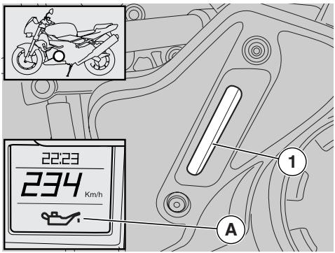
CHECKING AND TOPPING UP ENGINE OIL LEVEL
Carefully read page 58 (MAINTENANCE) and page 41 (ENGINE OIL).
NOTE Halve maintenance intervals if you are riding in rainy or dusty conditions, on rough road surfaces or when the vehicle is used in competitions.
Periodically check the engine oil level, change the oil after the first 1000km (625 mi) and successively every 10000 km (6250 mi), see page 63 (CHANGING ENGINE OIL AND THE ENGINE OIL FILTER).
CAUTION
In the vehicle is used for racing, change the engine oil every 5000km (3125 mi). Change oil more frequently if the vehicle is used in dusty conditions.
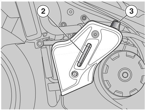
For the check, proceed as follows:
CAUTION
Engine oil level must be checked when the engine is warm. If you check level when the engine is cold, oil level may have temporarily dropped below the "MIN" mark.
This is not a problem, provided that the engine oil pressure symbol " (A) does not show on multifunction display, see page 14 (INSTRUMENTS AND INDICATORS TABLE).
NOTE To warm the engine and have the engine oil reach the operating temperature, do not let the engine idle with the vehicle at rest. According to the correct procedure, it is advisable to carry out the check after a trip or after covering approximately 15km (10 mi) on a road outside town (this is sufficient for the engine oil to reach the operating temperature).
Stop the engine, see page 54 (STOPPING).
Keep the vehicle in vertical position, with the two wheels resting on the ground.
Check oil level in the sight glass (2) visible through the special slot (1) in the left fairing.
MAX = maximum level
MIN = minimum level.
The difference between "MAX" and "MIN" amounts to approximately 500 cu. cm.
The level is correct when the oil almost reaches the "MAX" mark.
CAUTION
Never exceed the "MAX" mark, nor let the oil get below the "MIN" mark, in order to avoid serious damage to the engine.
If necessary, top up the engine oil by proceeding as follows:
Remove the left side fairing, see page 78 (REMOVING THE SIDE FAIRINGS).
Unscrew and remove the filler plug (3).
CAUTION
Do not put additives or other substances into the oil.
If you use a funnel or other tools, make sure that they are perfectly clean.
NOTE Use high-quality 15W - 50 oil, see page 114 (LUBRICANT CHART).
Top up the tank to correct level, see page 114 (LUBRICANT CHART).
CHANGING ENGINE OIL AND THE ENGINE OIL FILTER
CAUTION
Changing engine oil and engine oil filter can prove difficult; these operations are best left to experienced mechanics.
If necessary, contact your aprilia Authorised Dealer.
If you want to perform these operations personally, keep to the following instructions.
Carefully read page 58 (MAINTENANCE) and page 41 (ENGINE OIL).
NOTE Halve maintenance intervals if you are riding in rainy or dusty conditions, on rough road surfaces or when the vehicle is used in competitions.
Periodically check the engine oil level, see page 62 (CHECKING AND TOPPING UP ENGINE OIL LEVEL), change the oil after the first 1000km (625 mi) and successively every 10000km (6250 mi).
CAUTION
If the vehicle is used for racing, change engine oil every 5000km (3120 mi).
Change oil more frequently if the vehicle is used in dusty conditions.
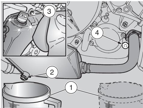
To change, proceed as follows:
NOTE Warm oil is more fluid and will drain out more easily and completely; ideal temperature is reached after engine has been running for about 20 minutes.
CAUTION
When warmed up, the engine contains hot oil. Be careful to avoid burns while carrying out the operations described below.
Remove the left side fairing, see page 78 (REMOVING THE SIDE FAIRINGS).
Clean off any dirt from the area around the filler plug (3) with a clean cloth.
Place a container (1) holding more than 4000 cu. cm under the drain plug (2) on the reservoir.
Unscrew and remove the drain plug (2) on the reservoir.
Unscrew and remove the filler plug (3).
Drain the oil and let it drip into the container (1) for a few minutes.
Check the sealing washer of the reservoir drain plug (2) and replace as required.
Screw and tighten the drain plug (2) onto the reservoir.
Drain plug (2) tightening torque: 15 Nm (1.5 kgm).
Place the container (1) underneath the engine crankcase, under the engine drain plug (4).
Unscrew and remove the engine drain plug (4).
Drain the oil and let it drip into the container (1) for a few minutes.
CAUTION
DO NOT DISPOSE OF THE OIL IN THE ENVIRONMENT. Dispose of engine oil - stored in a sealed container - through the nearest waste oil reclamation firm or through the supplier.
Remove any metal debris collected by the drain plug (4) magnet.
Screw and tighten the drain plug (4).
Drain plug (4) tightening torque: 12 Nm (1.2 kgm).
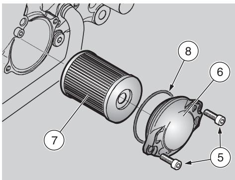
CHANGING THE ENGINE OIL FILTER
NOTE Halve maintenance intervals if you are riding in rainy or dusty conditions, on rough road surfaces or when the vehicle is used in competitions.
Change the engine oil filter every 10000 km (6250 mi) or anyway each time you change the engine oil.
Release the two screws (5) and remove the cover (6).
Remove the engine oil filter (7).
Never reuse a filter.
Spread a film of oil on the seal (8) of the new engine oil filter.
Insert the new oil filter.
Refit the cover (6). Refit and tighten the two screws (5).
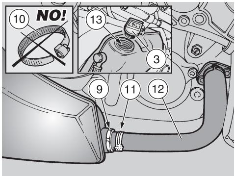
CLEANING THE ENGINE OIL FILTER LOCATED ON THE TANK
NOTE Halve maintenance intervals if you are riding in rainy or dusty conditions, on rough road surfaces or when the vehicle is used in competitions.
Clean the engine oil filter (7) located on the tank after covering the first 1000km (625 mi) and every 20000 km (12427 mi) (or every two oil changes) afterwards.
NOTE Have the appropriate special tool at hand:
-clamp installation pliers, see page 28 (SPECIAL TOOLS) OPT.
CAUTION
Upon installation, replace the click clamp that has been removed with a new one having the same dimensions, to be requested to an aprilia Authorised Dealer.
Do not attempt to reinstall the removed click clamp.
Do not replace a click clamp you have removed with a screw clamp (10) or with other types of clamps.
Release the click clamp (11).
Disconnect the hose (12).
Release and remove the engine oil filter (9) located on the reservoir and clean with an air line.
Check the engine oil filter (9) seal, fit and tighten the filter.
Engine oil filter (9) tightening torque: 30 Nm (3 kgm).
Connect the hose (12) and fit a new click clamp.
CAUTION
Do not put additives or other substances into the oil.
If you use a funnel or other tools, make sure that they are perfectly clean.
NOTE Use high-quality 15W - 50 oil, see page 114 (LUBRICANT CHART).
Pour from opening (13) about 3500 cu. cm of engine oil, see page 114 (LUBRICANT CHART).
Refit and tighten the filler plug (3).
Start the engine, see page. 48 (STARTING) and keep it idling for about one minute to let oil fill all points of the circuit.
Check oil level and top up if needed, see page 62 (CHECKING AND TOPPING UP ENGINE OIL LEVEL).
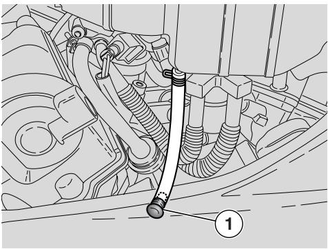
AIR FILTER
NOTE Halve maintenance intervals if you are riding in rainy or dusty conditions, on rough road surfaces or when the vehicle is used in competitions.
Check the air filter every 10000 km (6250 mi) or 12 months. Change it every 20000 km (12500 mi) or more frequently when you ride on dusty or wet roads.
In this case, clean the air filter after each ride following the partial cleaning procedure described below.
CAUTION
Cleaning the filter more frequently does not eliminate the need to change the filter at the specified intervals. Do not start the engine when the air filter is not in place.
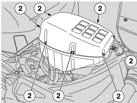
Do not clean the filter element with petrol or solvents. These products may cause the fuel to ignite in the fuel system, leading to personal injury and vehicle damage.
DO NOT RELEASE POLLUTING PRODUCTS INTO THE ENVIRONMENT.
Every 10000 km (6250 mi), remove the plug (1), drain its contents into a container and deliver it to a waste collection centre.
REMOVAL
Lift the fuel tank, see page 77 (LIFTING THE FUEL TANK).
Release and remove the seven screws (2).
Take off the air box cover (3).
Unscrew and remove the two screws (4).
Remove the air filter retaining bracket (5).
Extract the air filter (6).
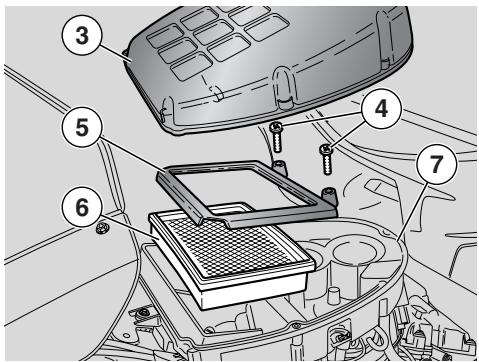
Check the seal (7) for wear or damage and replace as required.
CAUTION
Block off the intake funnels with clean cloths to prevent the ingress of dirt into the intake ducts. On refitting, make sure to remove the cloths and any other objects you may have placed into the airbox before installing the air box cover (3). Make sure the air filter is properly in place or it will let unfiltered air into the system. Note that early wear of piston rings and cylinder is frequently due to a defective or badly positioned air filter.
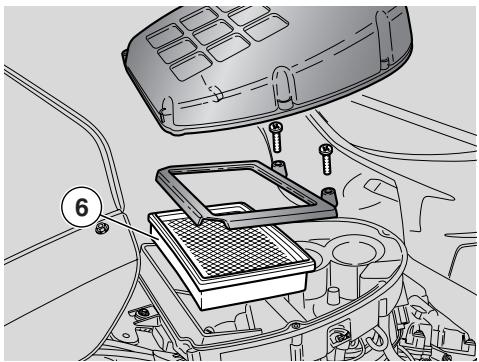
PARTIAL CLEANING
CAUTION
Do not press or hit the air filter meshing (6). Do not use a screwdriver or any other tools on the air filter.
Hold the air filter (6) in a vertical position and tap it repeatedly on a clean bench.
If needed, blow the air filter (6) with an air line. Aim the nozzle from the inside of the meshing outwards.
CAUTION
When cleaning the air filter, ensure the meshing is not torn. Always change a damaged air filter.
Clean the outer surface of the air filter (6) with a clean cloth.
REPLACEMENT
CAUTION
Never reuse a filter.
Replace the air filter (6) with a new air filter of the same type.
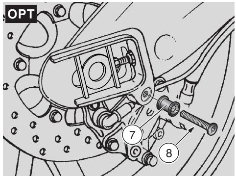
FITTING THE PINS FOR THE REAR WHEEL STAND OPT
Position the vehicle on the stand, see page 56 (PLACING THE VEHICLE ON THE STAND).
★ Fit the pin (7) into the suitable seat in the swinging arm.
Start the screw (8) into the threaded hole in the swinging arm and tighten.
POSITIONING THE VEHICLE ON THE REAR SUPPORT STAND OPT
Fit the two pins (7), see page 67 (FITTING THE PINS FOR THE REAR WHEEL STAND).
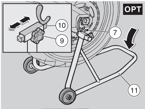
NOTE Have someone help you keep the vehicle in vertical position with the two wheels on the ground.
★ Slacken the knob (9).
Shift the fork-shaped support (10) so that its width matches the distance between the two pins fitted to the swinging arm.
Tighten the knob (9).
Slide both fork-shaped seats (10) of the stand (11) underneath the pins (7) fitted to the vehicle at the same time.
Place one foot on the rear end of the stand (11).
Push down on the stand (11).
CAUTION
Make sure that the vehicle is stable.

POSITIONING THE VEHICLE ON THE FRONT SUPPORT STAND OPT
Position the vehicle on the appropriate rear support stand, see page 67 (FITTING THE PINS FOR THE REAR WHEEL STAND) OPT.
Slide both lugs of the stand (12) into the holes (13) at the bottom ends of the front fork.
Place one foot on the front end of the stand (14).
Push down on the stand (14).
CAUTION
Make sure that the vehicle is stable.
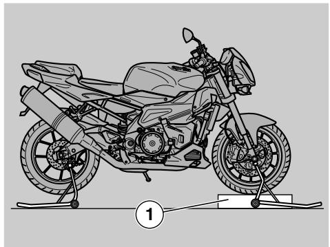
FRONT WHEEL
CAUTION
Removing and refitting the front wheel may prove difficult for unskilled operators.
If necessary, contact your aprilia Authorised Dealer.
If you wish to perform these operations yourself, keep to the following instructions.
Carefully read page 58 (MAINTENANCE). When disassembling and reassembling, be careful not to damage the brake hoses, the discs and the pads.
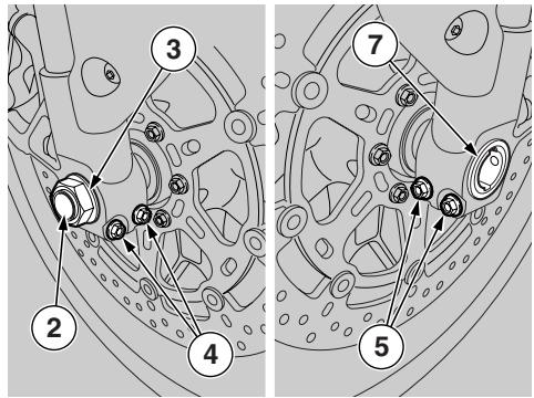
Riding with damaged rims may be dangerous for the rider, other persons and the vehicle.
Check the conditions of the wheel rim and have it changed if damaged.
DISASSEMBLY
Remove the front brake callipers, see page 71 (FRONT BRAKE CALLIPERS).
Place a support (1) under the tyre to hold the wheel in place once released.
CAUTION
Make sure that the vehicle is stable.
Have someone keep the handlebar steady in a position as for riding, so that the steering is locked.
Wheel nut (2) tightening torque: 80 Nm (8 kgm).
Undo and remove the wheel hub nut (2) and collect the washer (3).
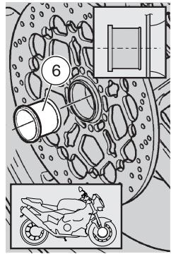
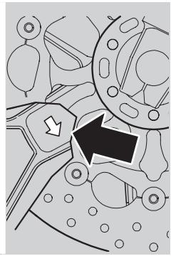
Wheel shaft clamp screws tightening torque: 22 Nm (2.2 kgm).
Slacken but do not remove the two wheel shaft pinch bolts (4) on the right side.
Slacken but do not remove the two wheel shaft pinch bolts (5) on the left side.
NOTE Note the direction of the spacer (6) placed on the right side to refit it correctly on assembly.
NOTE To facilitate the extraction of the wheel shaft, slightly raise the wheel.
Push on the threaded end of the wheel shaft (7) carefully. Tap with a plastic mallet if needed.
Hold the front wheel and withdraw the wheel shaft (7) manually.
Remove the wheel by withdrawing it from the front.
CAUTION
The spacer (6) should still be sitting in the wheel housing; if it slips off, refit it correctly (see REFITTING THE WHEEL).
REASSEMBLY
Smear a layer of grease all along the wheel shaft (7), see page 114 (LUBRICANT CHART).
CAUTION
While reassembling the wheel, be careful not to damage the brake pipes, discs and pads.
NOTE The next procedure is only required when the spacer (6) has slipped out of place.
Position the spacer (6) to the wheel with the larger diameter facing out.
CAUTION
The arrow mark on the hub points in the direction of rotation.
Make sure to refit the wheel in the correct direction: the arrow must be on the left side of the vehicle.
Position the wheel between the fork legs on the support (1).
WARNING
Danger of injury. Do not insert your fingers to align the holes.
Move the wheel until its central hole and the holes on the fork are aligned.
Slide the wheel shaft (7) fully home from the left side.
NOTE Make sure the wheel shaft (7) is fully in the hub.
Fit the washer (3) and screw the wheel hub nut (2) finger-tight.
NOTE Next, you will have to temporarily fit the two wheel shaft pinch bolts (5) on the left side. It is not necessary to tighten them to the final torque.
Start the two wheel shaft pinch bolts (5) in their holes on the left side and tighten just enough to prevent wheel shaft (7) rotation.
Tighten the nut (2) to the specified torque.
Wheel nut (2) tightening torque: 80 Nm (8 kgm).
Tighten the two wheel shaft pinch bolts (4) on the right side.
Wheel shaft clamp screws tightening torque: 22 Nm (2.2 kgm).
Slacken the two wheel shaft pinch bolts (5) on the left side.
Refit the front brake callipers, see page 71 (FRONT BRAKE CALLIPERS).
With pulled front brake lever, press the handlebar repeatedly, thrusting the fork downwards. In this way the fork legs will settle properly.
Place the vehicle on the side stand, see page 67 (POSITIONING THE VEHICLE ON THE REAR SUPPORT STAND).
Tighten the two wheel shaft pinch bolts (5) on the left side.
Wheel shaft clamp screws tightening torque (5): 22 Nm (2.2 kgm).
Make sure that the following components are not dirty:
- tyre;
- wheel;
- brake discs.
WARNING
After reassembly, pull the front brake lever repeatedly and check the correct functioning of the braking system.
Have the tightening torque, centring and balancing of the wheel checked by an aprilia Authorised Dealer, in order to avoid accidents that may be harmful for you and/or other people.
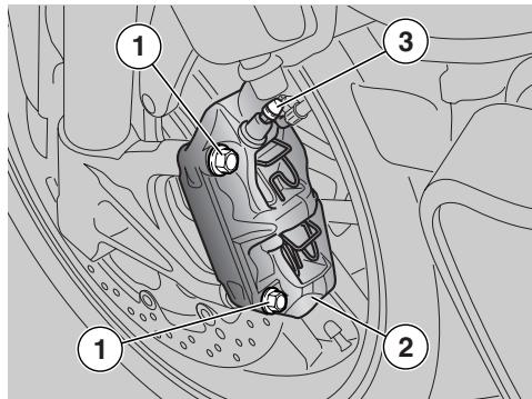
Carefully read page 58 (MAINTENANCE).

WARNING
A dirty disc will soil the pads, leading to loss of braking efficiency. Dirty pads must be replaced, while dirty discs must be cleaned with a high-quality degreaser.

CAUTION
When disassembling and reassembling, be careful not to damage the brake hoses, the discs and the pads.
NOTE To remove the front brake callipers, it is necessary to use the suitable front OPT and rear OPT wheel stands.
DISASSEMBLY
Position the vehicle on the appropriate front support stand, see page 68 (POSITIONING THE VEHICLE ON THE FRONT SUPPORT STAND)OPT.
CAUTION
Make sure that the vehicle is stable.
Rotate the wheel manually until bringing the space between two wheel spokes before the brake calliper.
Have someone keep the handlebar steady in a position as for riding, so that the steering is locked.
Brake calliper screws (1) tightening torque: 50 Nm (5 kgm).
★Unscrew and remove the two brake calliper screws (1).
CAUTION
Do not operate the front brake lever when the callipers are not in place, or the pistons might fall out leading to brake fluid spillage.
In this case consult an aprilia Authorised Dealer, who will carry out the proper maintenance operation.
★Withdraw the brake calliper (2) from the disc, leaving it attached to the hose (3).
Remove the other brake calliper as follows:
Repeat the operations marked with
REASSEMBLY
CAUTION
Proceed with care, in order not to damage the brake pads.
Position the brake calliper (2) to the disc so that the calliper mounting holes match the support holes.
WARNING
On assembly, replace both calliper retaining screws (1) with new ones of the same type.
★Screw and tighten the two calliper retaining screws (1).
Brake calliper screws tightening torque: 50 Nm (5 kgm).
Remove the other brake calliper as follows:
Repeat the operations marked with
Remove the front support stand OPT, see page 68 (POSITIONING THE VEHICLE ON THE FRONT SUPPORT STAND) OPT.
CAUTION
After reassembly, operate the brake lever repeatedly and check the braking system for proper operation.
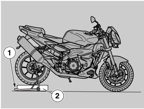
REAR WHEEL
CAUTION
Removing and refitting the rear wheel may prove difficult for unskilled operators.
If necessary, contact your aprilia Authorised Dealer.
If you wish to perform these operations yourself, keep to the following instructions.
Carefully read page 58 (MAINTENANCE). To avoid burns, allow some time for the engine and exhaust silencer to cool down completely before proceeding.
Use great care when removing the wheel to avoid damaging the brake lines, brake discs and brake pads.
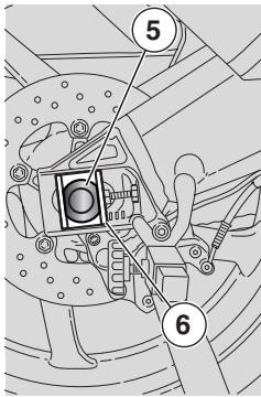
WARNING
Riding with damaged rims may be dangerous for the rider, other persons and the vehicle.
Check the conditions of the wheel rim and have it changed if damaged.
NOTE To remove the rear wheel, you will need the rear wheel stand OPT. Make sure to have it ready at hand.
DISASSEMBLY
Position the vehicle on the appropriate rear support stand (1), see page 67 (POSITIONING THE VEHICLE ON THE REAR SUPPORT STAND) OPT.
Place a support (2) under the tyre to hold the wheel in place once released.
Wheel nut (3) tightening torque: 120 Nm (12 kgm).
Undo and remove the wheel hub nut (3) and collect the washer (4).
NOTE To facilitate the extraction of the wheel shaft, slightly raise the wheel.
Withdraw the wheel shaft (5) from the right side.
NOTE Note the direction and position of the right (6) and left (7) chain sliders so as to refit them correctly on assembly.
Collect the right (6) and left (7) chain sliders.
NOTE Take the chain (8) off the sprocket (9) passing it on the outside.
Push the wheel forward and take the drive chain (8) off the rear sprocket (9).
Withdraw the wheel from the swinging arm from behind, carefully withdrawing the disc from the brake calliper.
CAUTION
Do not operate the rear brake lever after removing the wheel, since the pistons may go out of their seats and cause brake fluid leakage. In this case consult an aprilia Authorised Dealer, who will carry out the proper maintenance operation.
CAUTION
The left (10) and right (11) spacers should still be sitting in the wheel housings; if they slip off, refit them correctly (see next paragraph).
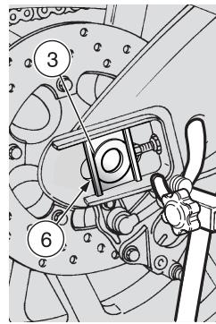
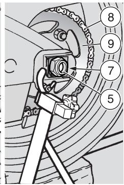
NOTE The brake calliper (13) carrier (12) is still attached to the right side of the swinging arm.
Proceed with care. If the final drive assembly (14) is mounted to the cushion drive hub (15), do not turn the rear wheel over or place it horizontally lying on the rear chain sprocket (A) side, or the final drive assembly will come off and the sprocket (9) might damage.
NOTE The removal of the final drive unit is not necessary if the wheel is in the normal running position (vertical) or in horizontal position with the rear sprocket facing upwards and in both cases secured against overturning.
NOTE Do not unscrew the five nuts (16). The whole final drive unit must be withdrawn from the flexible coupling holder.
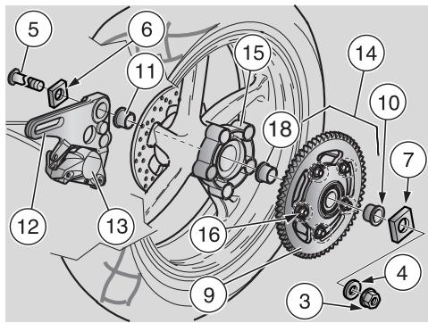
Place both hands (B) on the outer diameter of the sprocket (9) and withdraw the final drive assembly. Keep it parallel to wheel axis during removal.
REASSEMBLY
If you have removed the final drive assembly (14):
NOTE Fit the final drive assembly keeping it parallel to wheel axis and make sure the cushion drive rubbers become properly located into their seats in the cushion drive hub (15).
Place both hands (C) on the outer diameter of the sprocket (9) and insert the final drive assembly into the cushion drive hub (15).
CAUTION
Make sure the spacer (18) does not slip off the final drive assembly on refitting.
NOTE The next procedure is only required when the left (10) and/or right (11) spacers have slipped out of place.
Position the left spacer (10) and/or the right spacer (11) into their seats with the larger diameter facing away from the vehicle.
CAUTION
Before proceeding with the reassembly, make sure that support plate (12) of the brake calliper (13) is positioned correctly; the plate slot must be inserted in the appropriate stop pin (17) in the inner part of the swinging arm right section.
Insert the disc in the brake calliper carefully.
Place the wheel between the two arms of the swinging arm and over the support (2).
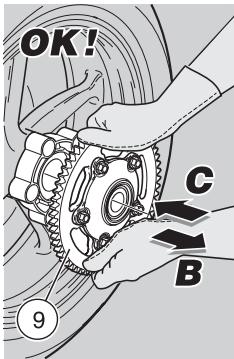
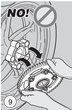
WARNING
Do not insert your fingers between the chain and the rear sprocket.
Push the wheel forward and wrap the drive chain (8) around the sprocket (9).
Fit the right (6) and left (7) chain sliders correctly into their seats in the swinging arm.
Uniformly apply a moderate quantity of grease on the wheel shaft (5), see page 114 (LUBRICANT CHART).
Danger of injury.
Do not insert your fingers to align the holes.
Move the wheel backwards, until its central hole and the holes on the swinging arm are aligned.
Rotate the carrier (12) complete with brake calliper (13) - it will pivot around the locating pin (17) - until matching the holes.
Push the wheel shaft (5) fully home from the right side.
NOTE Make sure the wheel shaft (5) is fully in and that shaft head locates correctly into the seat in the left chain slider (7).
Fit the washer and screw the wheel hub nut (3) finger-tight.
Check chain slack, see page 75 (DRIVE CHAIN).
Tighten the wheel hub nut (3) to the specified torque.
Wheel nut (3) tightening torque: 120 Nm (12 kgm).
Make sure that the following components are not dirty:
- tyre;
- wheel;
- brake disc.
CAUTION
After reassembly, pull the rear brake lever repeatedly and check the correct braking system operation.
Have the tightening torque's, centring and balancing of the wheel checked by an aprilia Authorised Dealer, in order to avoid accidents that may be harmful for you and/or other people.
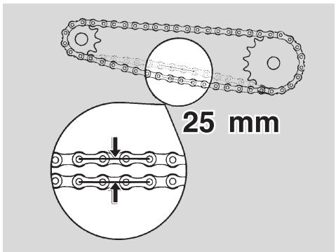
DRIVE CHAIN
Carefully read page 58 (MAINTENANCE).
The vehicle is equipped with an endless chain, in which a ring link joint is not used.
CAUTION
Exceeding slack in the chain may cause the chain to rattle or knock, resulting in a worn chain slider and guide.
Periodically check the slack and adjust it if necessary, see next paragraph.
To change the chain, contact an aprilia Authorised Dealer, who will ensure you prompt and accurate servicing.
Incorrect maintenance may cause the untimely wear of the chain and/or damages to the front sprocket and/or the rear sprocket.
NOTE Halve maintenance intervals if you are riding in rainy or dusty conditions, on rough road surfaces or when the vehicle is used in competitions.
CHAIN SLACK INSPECTION
To check the slack, proceed as follows:
Stop the engine.
Position the vehicle on the stand, see page 56 (PLACING THE VEHICLE ON THE STAND).
Position the gear shift lever in neutral.
Check chain slack by measuring the vertical movement of the chain lower section, midway between the sprockets. Movement should be approximately 25 mm.
Move the motorcycle forward, in such a way as to check the vertical oscillation of the chain even in other positions; the slack must be constant in all the wheel rotation phases.
CAUTION
If in some positions the slack is higher than in others, this means that there are crushed or seized links; in this case, contact an aprilia Authorised Dealer. To prevent the risk of seizures, lubricate the chain frequently, see page 76 (CLEANING AND LUBRICATION).
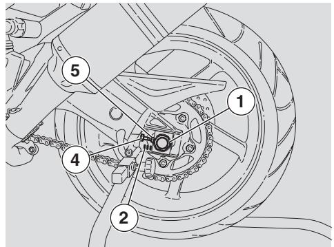
If the slack is evenly distributed, but above or below 25 mm, adjust it, see below.
CHAIN SLACK ADJUSTMENT
NOTE To adjust chain slack, you will need the rear wheel stand OPT. Make sure to have it ready at hand.
If the chain needs adjusting after the inspection, proceed as follows:
Position the vehicle on the appropriate rear support stand, see page 67 (POSITIONING THE VEHICLE ON THE REAR SUPPORT STAND) OPT.
Loosen the nut (1) completely.
NOTE Wheel centring is aided by fixed reference marks (2-3) located inside the seats of the chain sliders/tensioners fitted to the swinging arm before the wheel shaft.
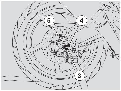
Loosen the two lock nuts (4).
Work the adjusters (5) and adjust chain slack, making sure to use the same reference mark settings (2-3) on both sides of the vehicle.
Tighten the two lock nuts (4).
Tighten the nut (1).
Wheel nut (1) tightening torque: 120 Nm (12 kgm).
Check the chain slack, see page 75 (CHAIN SLACK INSPECTION).
CHECKING CHAIN AND SPROCKETS FOR WEAR
Check the following parts every 10000 km (6250 mi). Visually inspect chain, front and rear sprockets looking for:
- damaged rollers;
- loose pins;
- dry, rusty, crushed or seized links;
excessive wear; - missing O-rings;
- sprocket or teeth excessively worn or damaged.
CAUTION
If the chain rollers are damaged, the pins are loose and/or the O-rings are damaged or missing, it is necessary to change the whole chain unit (both sprockets and chain).
Lubricate the chain frequently, especially if there are dry or rusty parts.
The crushed or seized links must be lubricated and made work again.
If this is not possible, contact an aprilia Authorised Dealer, who will provide for changing the chain.
CLEANING AND LUBRICATION
CAUTION
The drive chain links are fitted with O-rings that retain the grease inside.
Carry out the adjustment, lubrication, cleaning and change of the chain with great care.
Never wash the chain with water jets, steam jets, high-pressure water jets and highly inflammable solvents.
Wash the chain with naphtha or kerosene. If it tends to rust quickly, intensify the maintenance intervals.
Lubricate the chain every 1000 km (625 mi) and whenever it seems appropriate.
After washing the chain and letting it dry, lubricate it with spray grease for chains provided with sealing rings, see page 114 (LUBRICANT CHART).
CAUTION
The lubricants for chains available on the market may contain substances that are dangerous for the rubber sealing rings of the chain.
NOTE Do not use the vehicle soon after lubricating the chain, since due to the centrifugal force the lubricant would be sprayed outwards and dirty the surrounding areas.
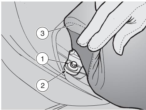
REMOVING THE RIDER SEAT
Position the vehicle on the stand, see page 56 (PLACING THE VEHICLE ON THE STAND).
★Partially raise the rear side edge of the seat.
Unscrew and remove the screw (1) and collect the bushing (2).
Screw (1) driving torque: 12 Nm (1.2 kgm).
The operations marked with must be performed on both sides of the vehicle.
Raise and remove the seat (3).
NOTE On refitting, insert the front tab of the seat into the corresponding seat.
CAUTION
Before riding, make sure that the seat (3) is properly positioned and secured firmly.
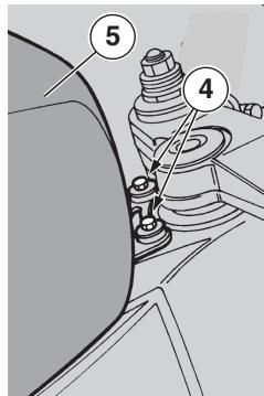
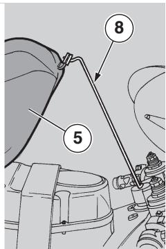
LIFTING THE FUEL TANK
Carefully read page 58 (MAINTENANCE) and page 29 (FUEL).
WARNING
Risk of fire.
Wait until the engine and the exhaust silencer have completely cooled down.
Fuel vapours are noxious for your health.
Before proceeding, make sure that the room in which you are working is properly ventilated.
Do not inhale fuel vapours.
Do not smoke or use open flames.
DO NOT DISPOSE OF FUEL IN THE ENVIRONMENT.
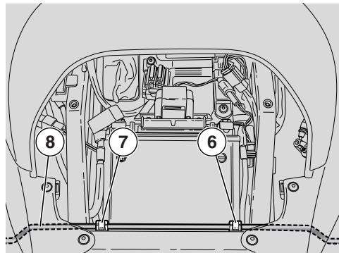
Remove the rider seat, see page 77 (REMOVING THE RIDER SEAT).
Remove the side panels, see page 82 (REMOVING THE SIDE PANELS).
Unscrew and remove the two retaining screws (4) at the front end of the fuel tank (5).
Release the fuel tank support rod (8) from its anchor points (6-7).
NOTE The rubber-coated end of the rod (8) must be introduced in the central hole of the steering shaft.
Lift the front end of the fuel tank (5) and insert the rod (8) as shown.
REMOVING THE SIDE FAIRINGS
Carefully read page 58 (MAINTENANCE).
WARNING
Wait until the engine and the exhaust silencer have completely cooled down.
Position the vehicle on the stand, see page 56 (PLACING THE VEHICLE ON THE STAND).
CAUTION
Handle the plastic and painted components with care to avoid scraping or damaging them.
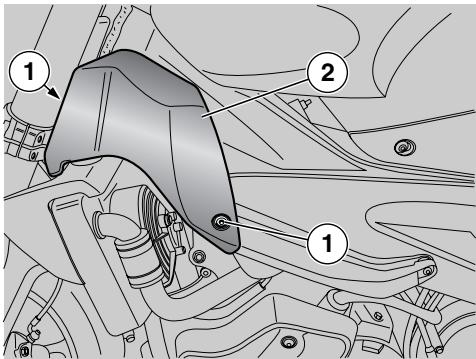
Unscrew and remove the two retaining screws (1) and collect the washers.
Remove the fairing (2).
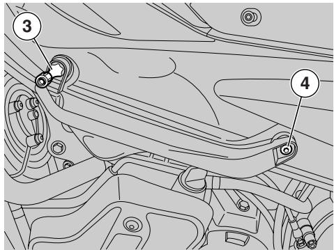
Unscrew and remove the retaining pin (3).
Unscrew and remove the retaining screw (4) and collect the washer.
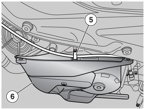
Release the quick-coupling to release the hose (5).
Remove the fairing (6).
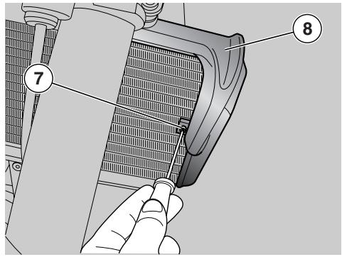
Release and remove the retaining screw (7).
Remove the fairing (8).
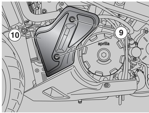
Unscrew and remove the two retaining screws (9) and collect the washers.
Remove the fairing (10).
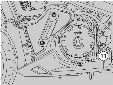
Unscrew and remove the left retaining screw (11) and collect the washer.
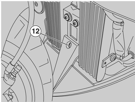
Unscrew and remove the left retaining screw (12) and collect the washer.
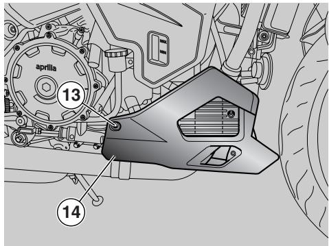
Unscrew and remove the right retaining screw (13) and collect the washer.
Remove the fairing (14).
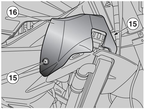
Unscrew and remove the two retaining screws (15) and collect the washers.
Remove the fairing (16).
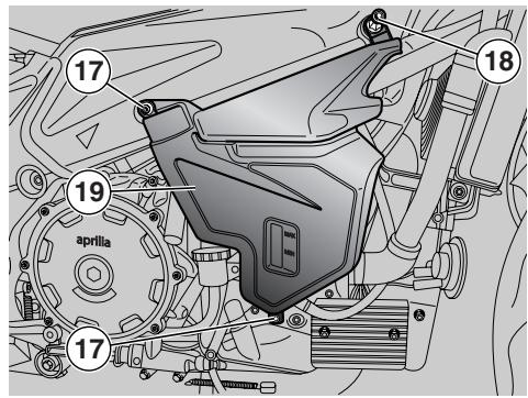
Unscrew and remove the two retaining screws (17) and collect the washers.
Unscrew and remove the retaining pin (18).
Remove the fairing (19).
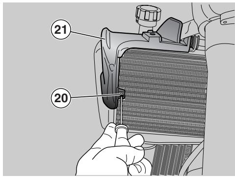
Unscrew and remove the retaining screw (20).
Remove the fairing (21).
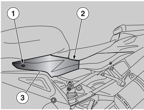
REMOVING THE SIDE PANELS
Remove the rider seat, see page 77 (REMOVING THE RIDER SEAT).
Unscrew and remove the screw (1).
Unscrew and remove the screw (2) (remove the front screw).
CAUTION
Handle the plastic and painted components with care to avoid scraping or damaging them.
Remove the side body panel (3).
NOTE Make sure the rear fittings are positioned correctly on refitting.
Repeat these operations to remove the other side body panel.
NOTE The passenger seat lock or passenger seat cover will remain attached to the left side panel.
To separate them, disconnect the Bowden cable from the lock on the inside of the side panel.
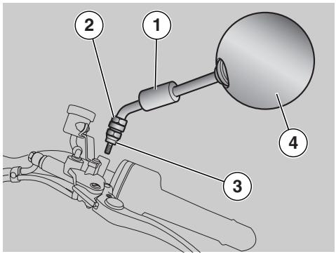
REMOVING THE REAR-VIEW MIRRORS
Place the vehicle on the centre stand on firm and level ground.
Lift the protection element (1).
CAUTION
Support the rear-view mirror (4) or it may accidentally fall down.
Hold the screw (2) and loosen the nut (3) completely.
CAUTION
Handle the plastic and painted components with care to avoid scraping or damaging them.
Remove the rear-view mirror (4).
NOTE Repeat these operations to remove the other rear-view mirror.

CAUTION
On refitting, adjust the rear-view mirrors and tighten the nuts to secure them firmly in place.
After refitting:
Adjust the inclination of the rear-view mirrors correctly.
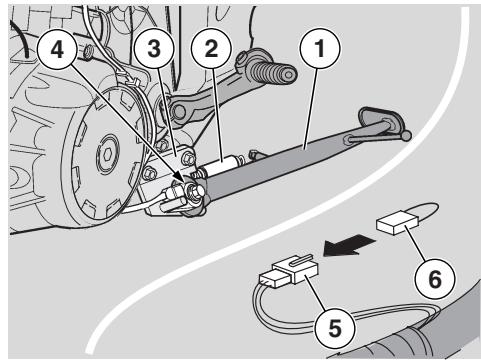
REMOVING THE SIDE STAND
Carefully read page 58 (MAINTENANCE).
Removal of the side stand (1) is only recommended for vehicles used for racing; the same applies to the following parts:
- springs (2),
bracket (3); - stand switch (4).
NOTE Removing the stand switch (4) interrupts the electric circuit. To restore it, connect the wiring (6) (aprilia part # 8127544), available from any aprilia Authorised Dealer, to the connector (5).
If the vehicle is used for racing, safety pegs (7) are available for installation to the rider footrests to avoid removal of the side stand.
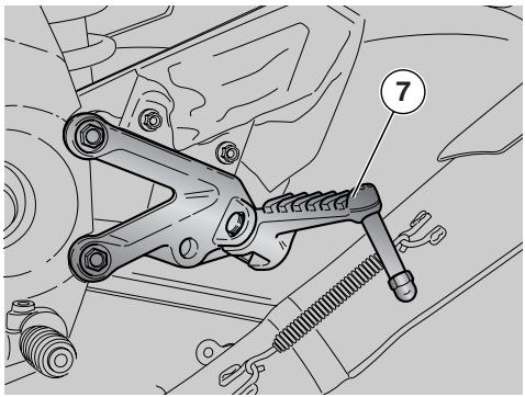
WARNING
Removal of the safety pegs (7) fitted to the rider footrests is only allowed after removal of the side stand.
CAUTION
Do not lean the vehicle against walls and do not lay it down on the ground. When the vehicle is without the side stand (side stand removal is allowed only for racing use), always park using the rear wheel stand OPT.
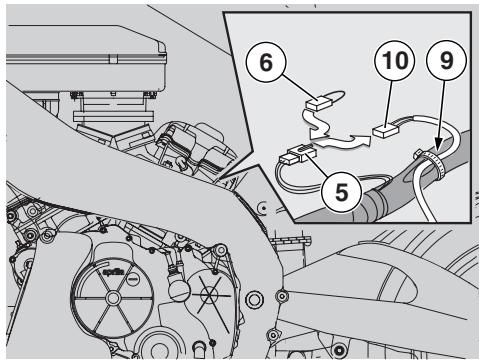
WARNING
It is forbidden to disconnect or remove the safety switch (4) separately from the stand.
When the stand switch (4) alone is disconnected or removed, engine starting is no longer inhibited with the stand down. This means the vehicle is capable of moving off with the stand down, which may result in an accident, leading to serious injury to the rider and other people and vehicle damage.
For the removal, proceed as follows:
Remove the left side fairing, see page 82 (REMOVING THE SIDE PANELS).
Do not pull on cables, hoses, connectors or on the wiring.
Lift the tank, see page 77 (LIFTING THE FUEL TANK).
Disconnect the electric connector (10) from the connector (5).
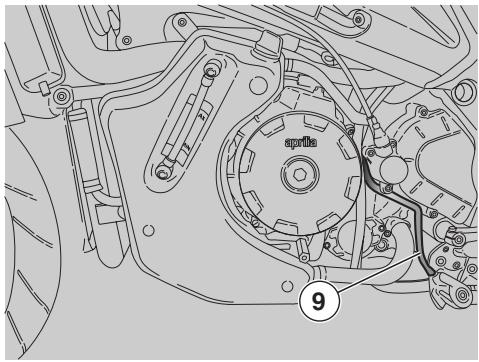
Connect the wiring (6) (aprilia part # 8127544) [in place of the electric connector (10)].
Withdraw the cable (9) completely.
Put back the fuel tank, see page 77 (LIFTING THE FUEL TANK).
Refit the left side fairing, see page 82 (REMOVING THE SIDE PANELS).
NOTE Support the stand, in order to prevent it from accidentally falling down.
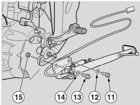
Driving torque of screws (11) and (13): 40 Nm (4 kgm).
Unscrew and remove the screw (11) and collect the washer (12).
Unscrew and remove the screw (13) while holding the nut (15) at the rear end with a spanner.
Remove the stand (1) complete with:
- springs (2),
bracket (3);
- stand switch (4).
Refit the screw (13), the washer (14) and the nut (15) and tighten to the specified torque.
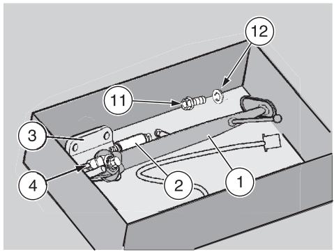
NOTE Store away the complete stand, the screw (11) and the washer (12) together. In this way, you will be able to refit them correctly when you intend to use the vehicle on public roads.
Refit the left side fairing, see page 78 (REMOVING THE SIDE FAIRINGS).
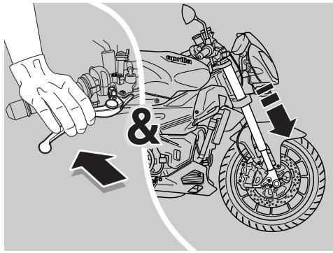
INSPECTING THE FRONT AND REAR SUSPENSIONS
Carefully read page 58 (MAINTENANCE).
NOTE Have the front fork oil changed by an aprilia Authorised Dealer, for guaranteed accurate, prompt service
NOTE Halve maintenance intervals if the vehicle is used in rainy or dusty conditions, on rough roads or for racing. Have the front fork oil changed after the first 10000 km (6250 mi) and then every 20000 km (12500 mi).
Carry out the following checks after the first 1000 km (625 mi) and every 10000 km (6250 mi) afterwards:
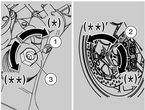
With pulled front brake lever, press the handlebar repeatedly, thrusting the fork downwards. The fork should compress in a smooth movement and must show no traces of oil on the legs.
Ensure that all components are properly tightened and check the front and rear suspension articulated joints for correct operation.
CAUTION
In the event of abnormal operation, or if qualified assistance is necessary, contact your aprilia Authorised Dealer.
FRONT SUSPENSION
After the first 30000 km (18750 mi) and then every 20000 km (12500 mi), check, clean and lubricate the fork oil seals. If necessary, have them replaced by an aprilia Authorised Dealer.
The front suspension is managed by a hydraulic fork, which is held to the steering tube by two yokes.
Each fork leg is fitted with suitable adjusters to modify suspension response. An upper adjuster screw (1) controls rebound damping, whereas a lower adjuster screw (2) controls compression damping. A top-mounted adjuster nut (3) controls spring preload.
SETTING THE FRONT FORK
CAUTION
Do not force the adjusters (1-2) beyond their limit stops in either direction, or the threads may strip. Set both fork legs to the same spring preload, compression and rebound damping settings: a vehicle whose fork legs are set to different settings will be unstable. When spring preload is increased, rebound damping should be increased accordingly. Failure to do so may result in the front end jerking unexpectedly when riding.
For fork setting, see next page.
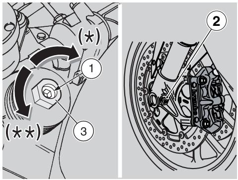
FORK
Factory setting is designed for any riding condition, low or high speed, with reduced or full load.
However, suspension setting may be modified to suit specific needs in accordance with vehicle use.
WARNING
For a correct setting of adjusters (1-2-3), first set the fork to the stiffest position (turn the adjuster fully clockwise) then set desired position (clicks and/or turns).
WARNING
Racing settings may only be used during official competitions or sports events authorised by the competent authorities and taking place in closed circuits or, anyway, away from public roads.
It is strictly prohibited to carry out adjustments for the use of the vehicle on racetracks and then ride it on roads or motorways.
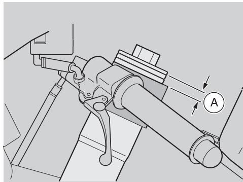
| FRONT SUSPENSION | Standard setting |
| Hydraulic adjustment with extended shock absorber, screw (1) | Tighten fully (*) and then slacken (**) by 1.5 turns |
| Hydraulic compression damping, screw (2) | Tighten fully (**) and then slacken (*) 1 turn |
| Spring preload, nut (3) | Tighten fully (*) and then slacken (**) 5 notches are in view |
| Fork height (A) (***) over top yoke (not including top cap) | 1 notches are in view |
(^) = clockwise
(^) = anticlockwise
(^*) = Have this adjustment carried out exclusively by an aprilia Authorised Dealer
For racing we recommend to fit the Ohlins multiadjustable front fork unit OPT. For the purchase contact an aprilia Authorised Dealer.
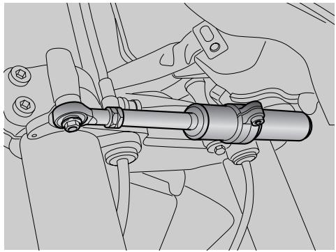
STEERING DAMPER
The standard model is equipped with a steering damper.
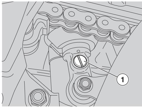
REAR SUSPENSION
The rear suspension consists of a springshock absorber unit, fixed to the frame by means of a uni-ball and to the swinging arm by means of lever systems.
The rear suspension is equipped with the following adjusters: a screw (1) for rebound, a ring nut (2) for adjusting the spring preload and a locking ring nut (3).
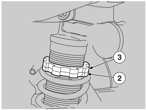
NOTE Halve maintenance intervals if you are riding in rainy or dusty conditions, on rough road surfaces or when the vehicle is used in competitions.
Check and if necessary adjust the rear shock absorber every 20000 km (12500 mi).
Factory setting is designed for racing.
However, rear suspension setting may be modified to suit specific needs in accordance with vehicle usage.
CAUTION
Before adjusting, first set the rear shock absorber to the stiffest setting [turn the adjusters (1) fully clockwise].
Do not force the adjusters (1) beyond their limit stops in either direction, or the threads may strip.
Unscrew the locking ring nut (3) by means of the appropriate spanner.
Adjust spring preload (A) through the adjusting ring nut (2) (see table).
When finished, tighten the ring nut (3).
Work the screw (1) to set shock absorber rebound damping (see table).
CAUTION
Set spring preload and rebound damping according to vehicle usage.
When you increase spring preload, you will have to increase rebound damping accordingly to avoid unexpected jerking when riding.
If necessary, contact your aprilia Authorised Dealer.
WARNING
Racing settings may only be used during official competitions or sports events authorised by the competent authorities and taking place in closed circuits or, anyway, away from public roads.
It is strictly prohibited to carry out adjustments for the use of the vehicle on racetracks and then ride it on roads or motorways.
| FRONT SUSPENSION | Standard setting |
| Spring length (preloaded) (A) | 147 mm |
| Rebound adjustment, screw (1) | tighten fully (*) and then slacken (**) by 25 click positions |
For racing we recommend to fit the Ohlins multiadjustable rear suspension unit OPT. For the purchase contact an aprilia Authorised Dealer.
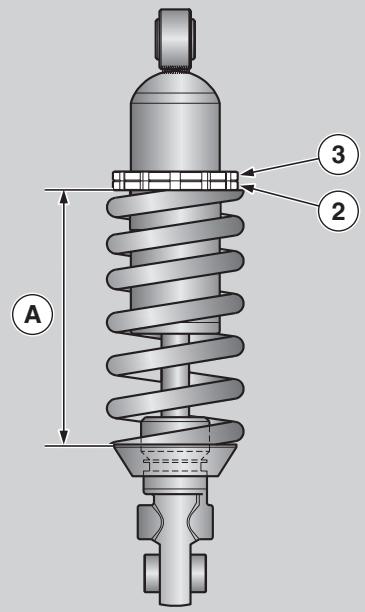
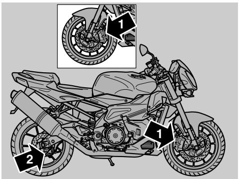
CHECKING THE BRAKE PADS FOR WEAR
Carefully read page 30 (BRAKE FLUID recommendations), page 31 (DISC BRAKES) and page 58 (MAINTENANCE).
NOTE The following information refer to a single braking system, but are valid for both.
NOTE Halve maintenance intervals if you are riding in rainy or dusty conditions, on rough road surfaces or when the vehicle is used in competitions.
Check the brake pad wear after the first 1000 km (625 mi) and successively every 2000 km (1250 mi) and before every trip.
The wear of the disc brake pads depends on the use, on the kind of ride and on the road.
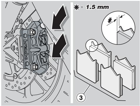
WARNING
Check the wear of the brake pads, especially before every trip.
To carry out a rapid checking of the wear of the pads, proceed as follows:
Position the vehicle on the stand, see page 56 (PLACING THE VEHICLE ON THE STAND).
NOTE The front (right and left) brake callipers are fitted with four brake pads each. The rear brake calliper has two brake pads.
Carry out a visual check between the disc and the pads, proceeding:
- front brake callipers (1): check the pads looking from above at the rear end;
from below at the rear to check the rear brake calliper (2).
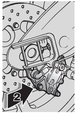
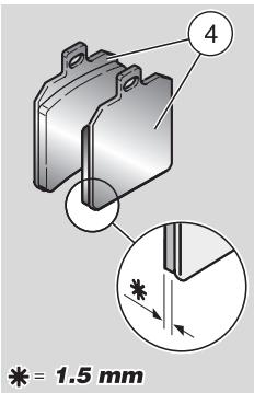
WARNING
The excessive wear of the friction material would cause the contact of the pad metal support with the disc, with consequent metallic noise and production of sparks from the calliper; braking efficiency, safety and soundness of the disc would thus be negatively affected.
If the thickness of the friction material [even of one front (3) or rear pad (4) only] has reduced to about 1.5mm (or even if only one of the wear indicators is not visible any longer):
- change all brake pads of both front brake callipers (right and left).
- for the rear brake calliper, have both pads of the calliper changed.
WARNING
Have the pads changed by an aprilia Authorised Dealer.
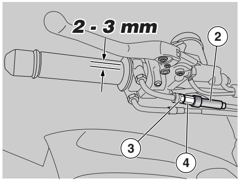
ADJUSTING THE THROTTLE TWISTGRIP
Carefully read page 58 (MAINTENANCE).
NOTE Halve maintenance intervals if you are riding in rainy or dusty conditions, on rough road surfaces or when the vehicle is used in competitions.
Have the accelerator control cables checked by an aprilia Authorised Dealer after the first 1000 km (625 mi) and successively every 10000 km (6250 mi).
The idle stroke of the throttle grip must be 2-3 mm, measured on the edge of the grip itself.
If not, proceed as follows:
Position the vehicle on the stand, see page 56 (PLACING THE VEHICLE ON THE STAND).
Take off the rubber gaiter (2).
Loosen the locknut (3).
Rotate the adjuster (4) until setting the specified free play.
After adjusting, tighten the locknut (3) and check free play again.
Refit the rubber gaiter (2).
CAUTION
After the adjustment, make sure that the rotation of the handlebar does not modify the engine idling rpm and that the throttle grip returns smoothly and automatically to its original position after being released.
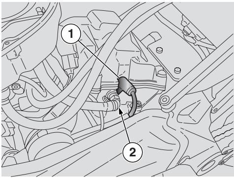
SPARK PLUGS
Carefully read page 58 (MAINTENANCE).
NOTE Halve maintenance intervals if you are riding in rainy or dusty conditions, on rough road surfaces or when the vehicle is used in competitions.
CAUTION
Check, clean or replace both spark plugs, one by one.
Check the spark plugs after the first 10000 km (6250 miles) and every 20000 km (12500 miles) afterwards.
If the vehicle is used for racing, change the spark plugs every 5000 km (3125 mi).
Periodically remove the spark plugs and clean them carefully, removing any carbon deposits; change them if necessary.
CAUTION
Always change both spark plugs together, even when only one needs replacing.
In order to gain access to the spark plugs:
WARNING
Before carrying out the following operations, let the engine and the silencer cool down until they reach room temperature, in order to avoid burns.
Lift the fuel tank, see page 77 (LIFTING THE FUEL TANK).
NOTE The vehicle is equipped with one spark plug for each cylinder.
The procedures described below apply to both spark plugs.
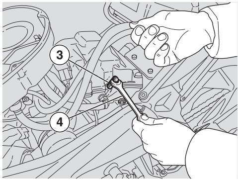
For the removal, proceed as follows:
Remove the cap (1) of the spark plug (2).
Remove any trace of dirt from the spark plug base.
Introduce the special spanner provided in the tool kit on the spark plug.
Fit the 13-mm open-end spanner (4) to the hexagon of the spark plug tool (3).
Unscrew the spark plug and extract it from its seat, taking care to prevent dust or other substances from getting inside the cylinder.
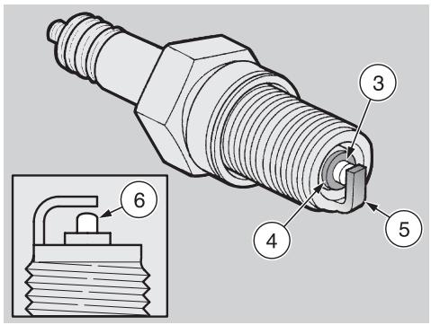
For the check and cleaning:
CAUTION
This vehicle is fitted with spark plugs with platinum electrodes.
Do not clean the spark plugs with a wire brush and/or abrasive products, use compressed air only.
Key:
centre electrode (3);
insulating (4);
side electrode (5).
Make sure that there are neither carbon deposits, nor corrosion marks on the electrodes and on the insulating material; if necessary, blow with compressed air to clean them.
If the spark plug has crackings on the insulating material, corroded electrodes, excessive deposits or the tip (6) of the central electrode (3) is rounded, it must be changed.
CAUTION
When changing the spark plug, check the thread pitch and length.
If the threaded part is too short, the carbon deposits will accumulate on the thread seat, and therefore the engine may be damaged during the installation of the right spark plug.
Use the recommended type of spark plugs only, see page 110 (TECHNICAL DATA), in order not to compromise the life and performance of the engine.
Electrode gap should be checked using a wire gauge (7) to avoid damaging the platinum coating.
Check electrode gap with a wire gauge (7).
CAUTION
Never attempt to adjust electrode gap.
Electrode gap should be 0.6 - 0.7 mm. If not so, change the spark plug.
Make sure that the washer (8) is in good condition.
For the installation:
Position the washer (8) and screw in the spark plug by hand in order not to damage the thread.
Tighten the spark plug by means of the spanner you will find in the tool kit, giving it half a turn to compress the washer.
Spark plug tightening torque: 20 Nm (2 kgm).
CAUTION
The spark plug must be well tightened, otherwise the engine may overheat and be seriously damaged.
Position the spark plug (2) cap (1) properly to prevent it from coming off due to engine vibration.
NOTE Repeat the above procedure for the spark plug of the other cylinder.
Put back the fuel tank, see page 77 (LIFTING THE FUEL TANK).

CHECKING THE SIDE STAND
Carefully read page 99 (CHECKING THE SWITCHES) and page 58 (MAINTENANCE).
The side stand (1) has two positions:
standard or folded up (at rest) (Pos.A);
- down (supporting the bike) (Pos.B).
Operation of the stand is the rider's responsibility.
It is important that no components interfere with side stand (1) rotation.
The springs (2) keep the stand in the desired position (extended or retracted).
Check for the following:
Position the vehicle on the appropriate rear support stand, see page 67 (POSITIONING THE VEHICLE ON THE REAR SUPPORT STAND) OFT.
The springs (2) must not be damaged, worn, rusty or weakened.
Make sure that the stand has no play in either position (extended and retracted).
Lower the stand to make sure the springs let it extend completely.
Pull the stand midway up and let go to make sure the springs let it retract completely.
The stand should turn smoothly: smear the joint with grease, if necessary, see page 114 (LUBRICANT CHART).
The side stand (1) is equipped with a safety switch (3) that inhibits ignition or stops the engine whenever a gear is engaged while the side stand (1) is down.
To determine proper operation of the safety switch (3), proceed as follows:
Remove the rear support stand, see page 67 (POSITIONING THE VEHICLE ON THE REAR SUPPORT STAND) OPT.
Sit astride the vehicle.
Fold up the side stand (1).
Start the engine, see page 48 (STARTING).
Release the throttle twistgrip (4) (Pos.C), let engine idle and then pull in the clutch lever (5).
Push down the gear change lever (6) to engage the first gear.
Lower the side stand (1) to operate the safety switch (3).
The following occurs:
- the engine must stop;
- the side stand down light "I" must come on.
CAUTION
If the engine does not stop, contact an aprilia Authorised Dealer.
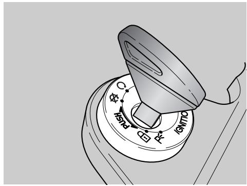
BATTERY
Carefully read page 58 (MAINTENANCE).
WARNING
Risk of fire.
Keep fuel and other flammable substances away from the electrical components.
Never invert the connection of the battery cables.
Ensure that the ignition switch is in position 忍 before connecting or disconnecting the battery, otherwise some components might damage.
Connect first the positive cable (+) and then the negative cable (-) .
Disconnect following the reverse order.
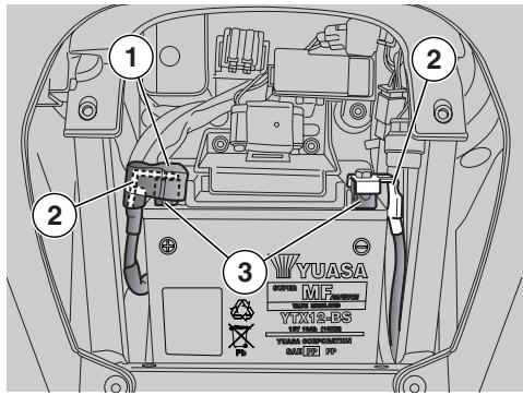
NOTE This vehicle is fitted with a maintenance-free battery which seldom needs inspecting, but may need charging from time to time.
CLEANING AND CHECKING BATTERY TERMINALS AND LEAD CONNECTIONS
Carefully read page 95 (BATTERY).
Make sure that the ignition switch is in position 忍
Remove the rider seat, see page 77 (REMOVING THE RIDER SEAT).
Remove the red protection element (1).
Make sure that the cable terminals (2) and the battery terminals (3) are:
- in good conditions (and not corroded or covered with deposits);
covered with neutral grease or Vaseline.
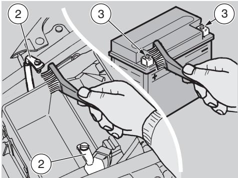
If necessary, proceed as follows:
Remove the battery, see page 96 (REMOVING THE BATTERY).
Brush the cable terminals (2) and the battery terminals (3) with a wire brush, in order to eliminate any trace of corrosion.
Install the battery, see page 98 (INSTALLING THE BATTERY).
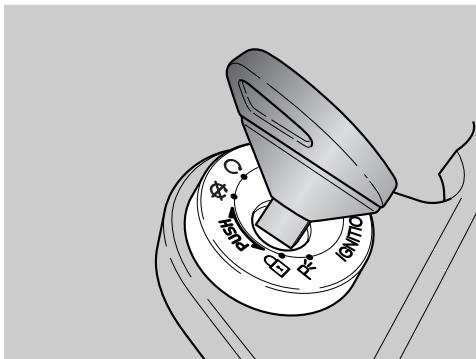
REMOVING THE BATTERY
CAUTION
When the battery is removed, the digital clock and red line setting will be reset to zero. To re-set these functions, see page 16 (MULTIFUNCTION COMPUTER).
Carefully read page 95 (BATTERY).
Make sure that the ignition switch is in position "X".
Remove the rider seat, see page 77 (REMOVING THE RIDER SEAT).
Release and remove the negative (-) terminal screw (1).
Slide the negative lead (2) aside.
Lift the red protective cap (3).
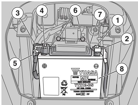
Release and remove the positive (+) terminal screw (4).
Move aside the positive cable (5).
Release and remove the two screws (6).
Remove the battery retaining bracket (7).
Grasp the battery (8) firmly and lift it out of its mount.
WARNING
Once it has been removed, the battery must be stored in a safe place and kept away from children.
Position the battery on a flat surface, in a cool and dry place.
Refit the rider seat, see page 77 (REMOVING THE RIDER SEAT).
NOTE For the installation of the battery, see page 98 (INSTALLING THE BATTERY).
CHECKING BATTERY FLUID LEVEL
Carefully read page 95 (BATTERY).
This vehicle is fitted with a maintenance-free battery. It is not necessary to check battery fluid level.
CHARGING THE BATTERY
Carefully read page 95 (BATTERY).
CAUTION
Do not remove the battery plugs or the battery may damage.
Remove the battery, see page 96 (REMOVING THE BATTERY).
Be sure to have a suitable battery charger at hand.
Set the battery charger to the desired charge rate (see chart below).
Connect the battery to the battery charger.
WARNING
During the recharging or the use, make sure that the room is properly ventilated and avoid inhaling the gases released during the recharging.
Switch on the battery charger.
| Charge rate | Voltage (V) | Amperes (A) | Time (hours) |
| Standard | 12 | 1,0 | 8 – 10 |
| Fast | 12 | 10 | 0.5 |
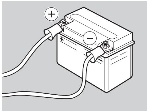
WARNING
Reassemble the battery only 5/10 minutes after disconnecting the recharge apparatus, since the battery continues to produce gas for a short lapse of time.

INSTALLING THE BATTERY
Carefully read page 95 (BATTERY).
Make sure that the ignition switch is in position "X".
Remove the rider seat, see page 77 (REMOVING THE RIDER SEAT).
NOTE The battery (1) must be positioned in its compartment with the terminals directed towards the upper part of the vehicle.
Put the battery (1) in its compartment.
Refit the battery retaining bracket (2).
CAUTION
Pay special attention to correctly position the bank angle sensor on the battery bracket (2).
Fit and tighten the screws (3).
WARNING
Upon reassembly, connect first the positive cable (+) and then the negative cable (-) .
Connect the positive terminal (+) by means of the screw (4).
Connect the negative terminal (-) by means of the screw (5).
Coat the terminals of cables and battery with neutral grease or Vaseline.
Refit the red protective cap (6).
Refit the rider seat, see page 77 (REMOVING THE RIDER SEAT).
CAUTION
When the battery is removed, the digital clock and red line setting will be reset to zero. To re-set these functions, see page 16 (MULTIFUNCTION COMPUTER).
LONG INACTIVITY OF THE BATTERY
CAUTION
When the motorcycle will not be ridden for over twenty days, disconnect the 30-A fuses, otherwise the multifunction computer will keep drawing current and the battery will deteriorate.
NOTE Disconnecting the 30-A fuses will reset the digital clock and red line setting. To re-set these functions, see page 16 (MULTIFUNCTION COMPUTER).
If the vehicle remains unused for more than fifteen days, it is necessary to recharge the battery, in order to prevent its sulphation, see page 97 (CHARGING THE BATTERY).
Remove the battery, see page 96 (REMOVING THE BATTERY) and put it in a cool and dry place.
It is important to check the charge periodically (about once a month), during the winter or when the vehicle remains unused, in order to prevent the deterioration of the battery.
Recharge it completely, using a standard charge, see page 97 (CHARGING THE BATTERY).
If the battery remains on the vehicle, disconnect the cables from the terminals.
CHECKING THE SWITCHES
Carefully read page 58 (MAINTENANCE).
The vehicle is provided with four switches:
1) Stoplight switch on the rear brake control lever;
2) Stoplight switch on the front brake control lever;
3) Safety switch on the side stand;
4) Switch on the clutch control lever.
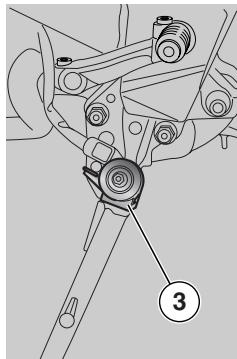
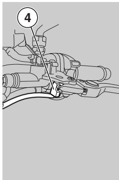
Make sure that there are no dirt or mud deposits on the switch; the pin must be able to move without interference, returning automatically to its initial position.
Make sure that the cables are connected correctly.
Check the spring (5): it must not be damaged, worn or weakened.

REPLACING THE FUSES
Carefully read page 58 (MAINTENANCE).
CAUTION
Never attempt to repair a defective fuse. Never use a fuse of a rating other than specified.
The use of unsuitable fuses may cause damages to the electric system or, in case of short circuit, even a fire.
NOTE When a fuse fitted in a particular position keeps blowing frequently, there might be a short circuit or overloading. In this case it is advisable to contact an aprilia Authorised Dealer.
Checking the fuses is recommended whenever an electric component fails to operate or is malfunctioning, or when the engine does not start.
Check the 15-A auxiliary fuses first and then the 30-A main fuses.
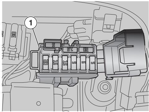
Check as follows:
Set the ignition switch to position "X" to avoid any accidental short circuit.
Remove the rider seat, see page 77 (REMOVING THE RIDER SEAT)
Open the cover of the auxiliary fuse box (1).
Extract and check the fuses one by one - a divided link bar (2) means that the fuse is blown.
Before replacing a fuse, try to find out the cause of the trouble, if possible.
Replace the damaged fuse with a new one having the same amperage.
NOTE If you use one of the spare fuses, put a new fuse in the proper seat.
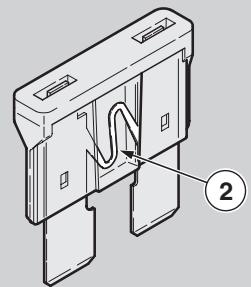
Remove the rider seat, see page 77 (REMOVING THE RIDER SEAT).
Repeat the above operations for the main fuses.
NOTE Disconnecting the 30-A fuses will reset the digital clock and red line setting.
To re-set these functions, see page 16 (MULTIFUNCTION COMPUTER).
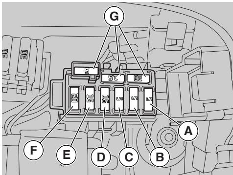
ARRANGEMENT OF 5-A AUXILIARY FUSES
A) From ignition key to: light relay, brake light, horn, parking lights.
B) From ignition key to: turn indicators, instrument panel.
C) From battery to: key positive brought to ECU.
ARRANGEMENT OF 15-A AUXILIARY FUSES
D) From battery to: speed sensor, fuel pump, relay, starter, lambda sensor.
E) From battery to: cooling fan relay, coils, fuel injectors, air intake flaps, camshaft position sensor.
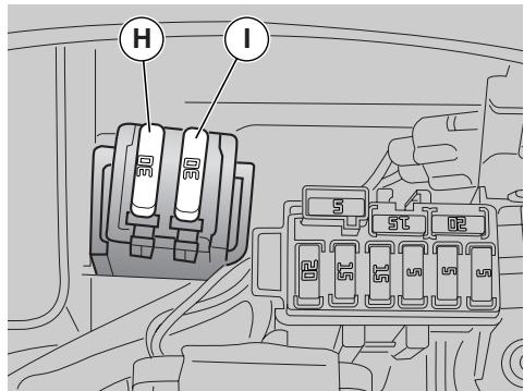
ARRANGEMENT OF 20-A AUXILIARY FUSES
F) From ignition switch to: high beam lights, low beam lights.
NOTE There are three spare fuses (G). ARRANGEMENT OF 30-A MAIN FUSES
H) Battery charging and vehicle loads (red and red/white wires).
1) Injection loads (red and red/white wires).
NOTE There is one spare fuse (L).
VERTICAL ADJUSTMENT OF THE HEADLIGHT BEAM
NOTE To check the direction of the headlight beam, specific procedures must be adopted, in accordance with the regulations in force in the country where the vehicle is used.
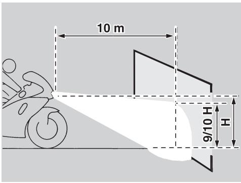
To adjust the headlight beam:
Position the vehicle on the stand, see page 56 (PLACING THE VEHICLE ON THE STAND).
Working from the rear left side of the headlight fairing, fit a short cross-headed screwdriver to the adjuster screw (1) and adjust as follows:
- TIGHTEN (clockwise) to raise the beam;
SLACKEN (anticlockwise) to lower the beam.
Repeat process for the right beam.
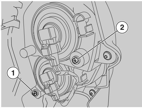
After the adjustment:
WARNING
Make sure that the vertical adjustment of the headlight beam is correct.
CAUTION
The headlights are also fitted with adjuster screws (2) for horizontal beam adjustment;
we advise against disturbing standard setting, unless such adjustment is mandatory in your country. Correct beam horizontal adjustment is performed at the factory.
TAPING OF THE HEADLIGHT
If front lights are shielded with tape (for track use), it is recommended to disconnect the front light bulb connectors or the reflector will overheat due to lack of air cooling.
CAUTION
Secure and shield properly any disconnected cables to prevent them from hindering handlebar rotation and becoming wet.
CAUTION
Restore all electric connections before using the vehicle on the road.
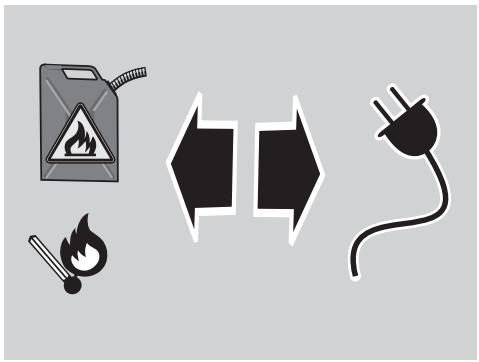
BULBS
Carefully read page 58 (MAINTENANCE).

WARNING
Risk of fire.
Keep fuel and other flammable substances away from the electrical components.


CAUTION
Before proceeding to change a bulb, set the ignition switch to "×" and allow some time for the bulb to cool down.
Change the bulb wearing clean gloves or using a clean and dry cloth.
Do not leave fingerprints on the bulb, since these may cause its overheating and consequent breakage.
If you touch the bulb with bare hands, remove any fingerprint with alcohol, in order to avoid any damage.
DO NOT FORCE THE ELECTRIC CABLES.
NOTE Before changing a bulb, check the fuses, see page 100 (REPLACING THE FUSES).
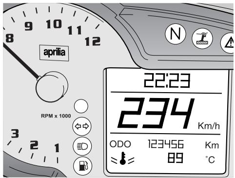
REPLACING THE INSTRUMENT PANEL LED
If you need assistance or technical advice, contact an aprilia Authorised Dealer, who can ensure you prompt and accurate servicing.

CAUTION
The instrument panel is equipped with LED lighting and if a failure occurs the complete instrument panel shall be replaced.
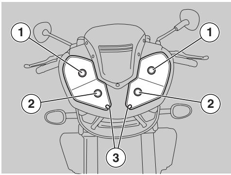
CHANGING THE HEADLIGHT BULBS
Carefully read page 103 (BULBS).
The headlight fairing is shown removed from the vehicle for better clarity. In fact, the high and low beam bulbs can be replaced with the headlight fairing in place. The headlight accommodates:
- Two high beam bulbs (1).
- Two low beam bulbs (2).
- Two parking light bulbs (3).
High beam and low beam use the same bulbs.
If one of the bulbs (2) is damaged and no spare bulb is available, you may replace it with one of the bulbs (1).
This is only intended to help you ride back home or reach the nearest parts shop. Replace the damaged bulb as soon as possible.
To change the bulbs:
Position the vehicle on the stand, see page 56 (PLACING THE VEHICLE ON THE STAND).
HIGH AND LOW BEAM BULBS
NOTE Disconnect one connector at a time to avoid confusing the various connectors when refitting.
When high and low beam bulb connectors must be removed at the same time, mark them with their positions and make sure to refit them in the correct positions on assembly.
Remove the upper side cover, see page 78 (REMOVING THE SIDE FAIRINGS).
CAUTION
Do not pull on the wires to extract the bulb connector.
Disconnect the connector (4).
Rotate the lock ring anticlockwise and extract the bulb holder (5).
Fit a new bulb of equal rating.
Refit the bulb holder into the seat and rotate clockwise to lock in place.
Refit the connector (4).
CAUTION
Do not pull on the wires to extract the bulb connector.
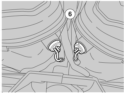
PARKING LIGHT BULB.
CAUTION
To extract the bulb holder, do not pull the electric wires.
Grasp the parking light bulb holder (6) and pull to extract.
Remove the bulb and fit a new bulb of equal rating.
NOTE Make sure the bulb is correctly located in the bulb holder.
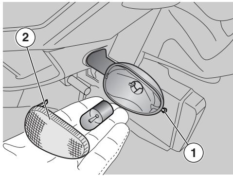
CHANGING THE FRONT AND REAR TURN INDICATOR BULBS
Carefully read page 103 (BULBS).
Position the vehicle on the stand, see page 56 (PLACING THE VEHICLE ON THE STAND).
Unscrew and remove the screw (1).
CAUTION
While removing the lens, proceed carefully in order not to break the locating peg.
Remove the lens (2).
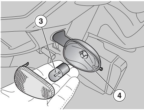
CAUTION
On refitting, ensure that the lens locates properly into its slot. Tighten the screw (1) moderately and carefully, to avoid damaging the lens.
Press the bulb (3) slightly and rotate it anticlockwise.
Extract the bulb (3) from its seat.
CAUTION
Insert the bulb into the bulb holder, so that the two pins slide into the slots in the holder.
Install a new bulb of equal rating.
CAUTION
If the reflector (4) comes off its seat, refit it correctly.
REPLACING THE NUMBER PLATE LIGHT BULB
Carefully read page 103 (BULBS).
Position the vehicle on the stand, see page 56 (PLACING THE VEHICLE ON THE STAND).
Remove passenger seat/seat cover, see page 26 (UNLOCKING/LOCKING THE PASSENGER SET/SEAT COVER).
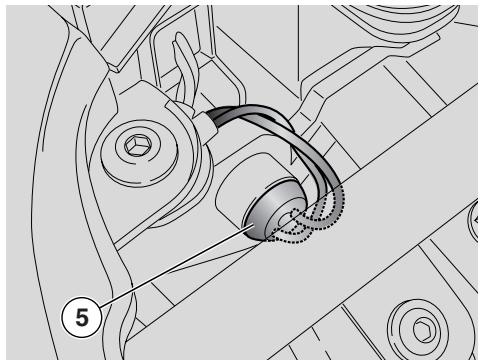
CAUTION
To extract the bulb holder, do not pull the electric wires.
Extract the number plate light bulb holder (5).
Remove the bulb and fit a new bulb of equal rating.
NOTE Make sure the bulb is correctly located in the bulb holder.
TRANSPORT
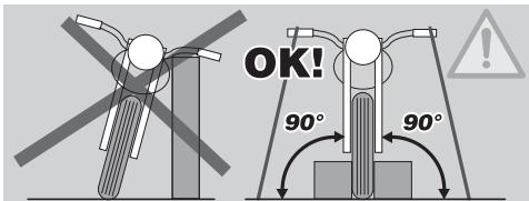
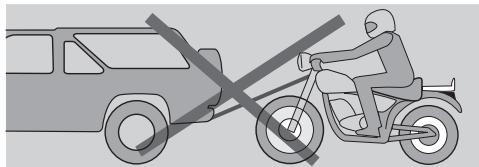
During transport, the vehicle must be kept in vertical position, it must be firmly anchored and the 1^st gear must be engaged, in order to avoid any leak of fuel, oil, coolant.
CAUTION
In case of failure, do not tow the vehicle, but ask for assistance.
CLEANING
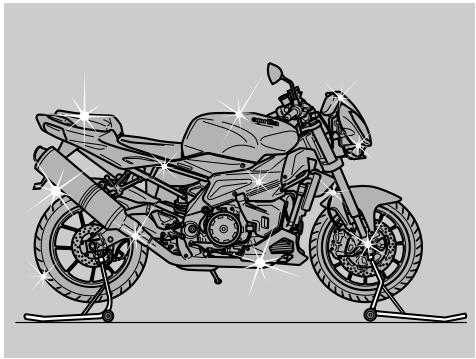
Clean the vehicle frequently if it is used in particular areas or conditions, such as:
- Polluted areas (cities and industrial areas).
- Areas characterised by a high percentage of salinity and humidity (sea areas, hot and humid climates).
- Particular conditions (use of salt and anti-ice chemical products on the roads during the winter).
- Avoid leaving deposits of industrial and polluting powders, tar spots, dead insects, bird droppings, etc. on the body.
- Avoid parking the vehicle under trees, since in some seasons residues, resins, fruits or leaves fall down, which contain substances that may damage the paint.

WARNING
After the vehicle has been washed, its braking functions could be temporarily impaired because of water on the braking surfaces.
Calculate long braking distances to avoid accidents.
Brake repeatedly to restore normal conditions.
Carry out the preliminary checking operations, see page 110 (TECHNICAL DATA).
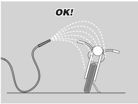
To remove dirt and mud from the painted surfaces use a low-pressure water jet, carefully wet the dirty parts, remove mud and filth with a soft car sponge impregnated with a lot of water and shampoo (2 - 4% parts of shampoo in water).
Then rinse with plenty of water and dry with chamois leather.
To clean the outer parts of the engine use a degreaser, brushes and wipers.
Any parts in anodised aluminium or any painted parts such as forks, rims, frame, footpegs, etc. shall be washed only with water and mild soap. Too much aggressive detergents can damage the surface treatment of these components.
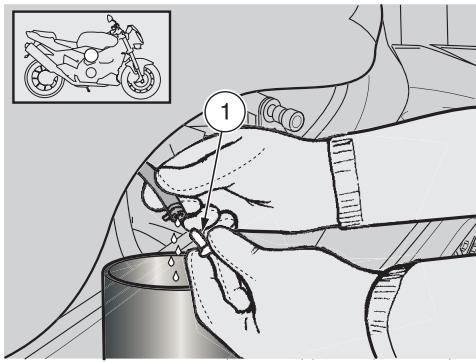
After washing the vehicle, always:
Remove the cap (1).
Empty its content into a container and deliver it to a salvage centre.
CAUTION
To clean the lights, use a sponge soaked with water and a mild detergent, rubbing the surfaces delicately and rinsing frequently with plenty of water.
Polish with silicone wax only after having carefully washed the vehicle.
Do not use polishing paste on matt paints.
Do not wash the vehicle under the sun, especially during the summer, when the body is still warm, since if the shampoo dries before being rinsed away, it can damage the paint.

Do not use fluids at a temperature exceeding 40^ to clean the plastic components of the vehicle.
CAUTION
Do not aim high-pressure water or air jets or steam jets on to the following components: wheel hubs, controls on the right and left side of the handlebar, bearings, brake master cylinders, instruments and indicators, exhaust pipes, glove/tool kit compartment, ignition switch/steering lock, radiator wings, fuel cap, lights and electric connections.
Do not use alcohol, fuel or solvents to clean the rubber and plastic parts and the seat: use only water and mild soap.
WARNING
Do not apply protection waxes onto the seat, in order not to make it too slippery.
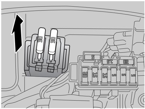
LONG PERIODS OF INACTIVITY
CAUTION
When the motorcycle will not be ridden for over twenty days, disconnect the 30-A fuses, otherwise the multifunction computer will keep drawing current and the battery will deteriorate.
NOTE Disconnecting the 30-A fuses will reset the digital clock and red line setting. To re-set these functions, see page 16 (MULTIFUNCTION COMPUTER).
After a long period of inactivity of the vehicle some precautions are necessary to avoid any problem.
Further, it is important to carry out the necessary repairs and a general check up before the period of inactivity, since you could forget to carry them out later.
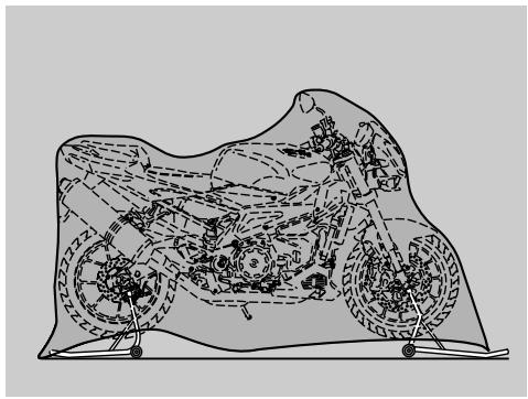
Proceed as follows:
Remove the battery, see page 96 (REMOVING THE BATTERY) and page 99 (LONG INACTIVITY OF THE BATTERY).
Wash and dry the vehicle, see page 107 (CLEANING).
Polish the painted surfaces with wax.
Inflate the tyres, see page 40 (TYRES).
Place the vehicle in an unheated, nothumid room, away from sunlight, with minimum temperature variations.
Wrap and tie a plastic bag around the exhaust pipe opening to keep moisture out.
NOTE Place the vehicle on the front OPT and rear Opt wheel stands so that both wheels are off the ground.
Position the vehicle on the appropriate front support stand, see page 68 (POSITIONING THE VEHICLE ON THE FRONT SUPPORT STAND) OPT.
Position the vehicle on the appropriate rear support stand, see page 67 (POSITIONING THE VEHICLE ON THE REAR SUPPORT STAND) OPT.
Cover the vehicle avoiding the use of plastic or waterproof materials.
AFTER STORAGE
NOTE Remove the plastic bag from the exhaust pipe.
Uncover and clean the vehicle, see page 107 (CLEANING).
Check the charge of the battery, see page 97 (CHARGING THE BATTERY) and install it, see page 98 (INSTALLING THE BATTERY).
Refill the fuel tank, see page 29 (FUEL).
Carry out the preliminary checking operations, see page 110 (TECHNICAL DATA).
WARNING
Have a test ride at moderate speed in a low-traffic area.
TECHNICAL DATA
| DIMENSIONS | Max. Length | 2025 mm |
| Max. Width | 830 mm | |
| Max. height (front fairing included) | 1100 mm | |
| Seat height | 810 mm | |
| Wheelbase | 1410 mm | |
| Min. ground clearance | 150 mm | |
| Weight ready for starting | 209 kg | |
| ENGINE | Model | V990 NG |
| Type | 4-stroke V 60° twin-cylinder, with 4 valves per cylinder, DOHC. | |
| Number of cylinders | 2 | |
| Total displacement | 997.6 cu. cm | |
| Bore/stroke | 97 mm/67.5 mm | |
| Compression ratio | 11.8 ± 0.5: 1 | |
| Starting | electric | |
| Engine idling rpm | 1250 ± 100 rpm | |
| Clutch | multiplate wet clutch, hydraulically operated, control on left side of handlebar and PPC device | |
| Lubrication system | dry sump with separate oil reservoir and oil cooler | |
| Air filter | with dry filter cartridge | |
| Cooling | liquid-cooled | |
| TRANSMISSION | Type | mechanical, 6 gears with foot control on the left side of the engine |
| CAPACITY | Fuel (reserve included) | 18 l |
| Fuel reserve | 4 ± 1 l | |
| Engine oil | oil change 3700 cu. cm - oil and oil filter change 3900 cu. cm | |
| Fork fluid | 520 ± 2.5 cu. cm (per leg) | |
| Coolant | 2.2 l (50% water + 50% antifreeze with ethylene glycol) | |
| Seats | 2 | |
| Vehicle max. load | 192 kg (rider + passenger + luggage) |
| Ratio | Primary | Secondary | Final ratio | Total ratio | |
| 1st | 31/60 = 1 : 1.935 | 15/34 = 1 : 2.267 | 16/40 = 1 : 2.500 | 1:10.986 | |
| 2nd | 19/31 = 1 : 1.632 | 1:7.895 | |||
| GEAR RATIOS | 3rd | 20/26 = 1 : 1.300 | 1:6.290 | ||
| 4th | 22/24 = 1 : 1.091 | 1:5.279 | |||
| 5th | 25/24 = 1 : 0.960 | 1:4.645 | |||
| 6th | 26/23 = 1 : 0.885 | 1:4.280 | |||
| DRIVE CHAIN | Type | endless (with no connection link) with sealed links | |||
| Model | 525 | ||||
| FUEL SUPPLY | Type | electronic injection (Multipoint) | |||
| SYSTEM | Throttle | Ø 57 mm | |||
| FUEL SUPPLY | Fuel | premium-grade unleaded petrol, minimum octane rating 95 (ROM) and 85 (MON). | |||
| FRAME | Type | double beam, inclined in aluminium alloy, box-type. | |||
| Steering head angle | 25° | ||||
| Trail | 101.7 mm (with tyre 120/70) | ||||
| SUSPENSIONS | Front | adjustable hydraulic upside-down fork, Ø 43 mm | |||
| Stroke | 120 mm | ||||
| Rear | aluminium alloy double-sided swinging arm with progressive linkage and APS system. Adjustable hydraulic shock absorber in rebound and compression damping | ||||
| Wheel travel | 133 mm | ||||
| BRAKES | Front | twin floating disc - Ø 320 mm, four-piston callipers - Ø 34 mm | |||
| Rear | Disc brake - Ø 220 mm, twin-piston calliper - Ø 32 mm | ||||
| WHEEL RIMS | Type | light alloy, removable shaft | |||
| Front | 3.50 x 17" | ||||
| Rear | 6.00 x 17" | ||||
| TYRES | Original equipment: | |
| Type: | PIRELLI DIABLO CORSA; METZELER SPORTEC M1; MICHELIN PILOT SPORT E; DUNLOP SPORTMAX D208RR | |
| Front | 120/70-ZR 17" | |
| Inflating pressure | 2.5 atm (250 KPa) | |
| Rear | 190/50 ZR 17" | |
| Inflating pressure | 2.8 atm (280 KPa) | |
| alternative: | ||
| Type: | PIRELLI SUPERCORSA PRO; METZELER RENNSPORT; MICHELIN PILOT POWER RACING; METZELER SPORTEC M1 (180/55 ZR17" only) | |
| Front | 120/70-ZR 17" | |
| Rear | 180/55 ZR 17" - 190/55 ZR17 | |
| SPARK PLUGS | Standard | NGK R DCPR9E |
| Spark plug gap | 0.6 ÷ 0.7 mm | |
| Resistance | 5 kΩ | |
| ELECTRIC SYSTEM | Battery | 12 V - 10 Ah |
| Main fuses | 30 A | |
| Auxiliary fuses | 5 A, 15 A, 20 A | |
| Generator (with permanent magnet) | 12 V - 500 W | |
| BULBS | (Halogen) low beam | 12 V - 55 W H11 x 2 |
| (Halogen) high beam | 12 V - 55 W H11 x 2 | |
| Front parking light | 12 V - 5 W x 2 | |
| Direction indicators | 12 V - 10 W AMBER (USA version 12 V - 10 W) | |
| Number plate light | 12 V - 5 W | |
| Rear parking lights/Stoplight | LED | |
| Revolution counter | LED | |
| Left multifunction display lighting | LED |
WARNING LIGHTS Neutral. LED
Direction indicators.. LED
Fuel reserve LED
High beam. LED
Stand down LED
Warning light. LED
Red line setting LED
Immobiliser. LED
LUBRICANT CHART
(Recommended) Engine oil: EXTRA RAID 4, SAE 15W - 50 or Agip TEC 4T SAE 15W - 50.
As an alternative to recommended oils, top brand oils meeting or exceeding CCMC G-4 A.P.I. SG specifications can be used.
(Recommended) Fork oil: F.A. 5W, F.A. 20W or Agip FORK 5W or Agip FORK 20W.
When you wish to obtain an intermediate response between those offered by F.A. 5W and F.A. 20W oils, you may mix the different products as follows:
SAE 10W = F.A. 5W67% of volume + F.A. 20W 33% of volume
Agip FORK 5W 67% of volume + Agip FORK 20W 33% of volume.
SAE 15W = F.A. 5W 33% of volume + F.A. 20W 67% of volume
Agip FORK 5W 33% of volume + Agip FORK 20W 67% of volume.
Bearings and other lubrication points (recommended): Bimol Grease 481, AUTOGREASE MP or Agip GREASE 30.
As an alternative to recommended grease, use top brand rolling bearing grease that will resist a temperature range of -30^ + 140^ , with dripping point 150^ - 230^ , high corrosion protection, good resistance to water and oxidisation.
Battery lead protection: Neutral grease or Vaseline.
Spray grease for chains (recommended): CHAIN SPRAY or Agip CHAIN LUBE.
WARNING
Use new brake fluid only. Do not mix different makes or types of oil without having checked bases compatibility.
Recommended brake fluid: the system is loaded with (Compatible DOT 5).

Autofluid FR. DOT 4 (Compatible DOT 5); Agip BRAKE 5.1 DOT 4
WARNING
Use new clutch fluid only
(Recommended) clutch fluid: Autofluid FR. DOT 4 (Compatible DOT 5); Agip BRAKE 5.1 DOT 4 (Compatible DOT 5).
WARNING
Use only nitrite-free antifreeze and anticorrosive, ensuring protection at -35^ at least.
(Recommended) Coolant: ECOBLU 40^ or Agip COOL.
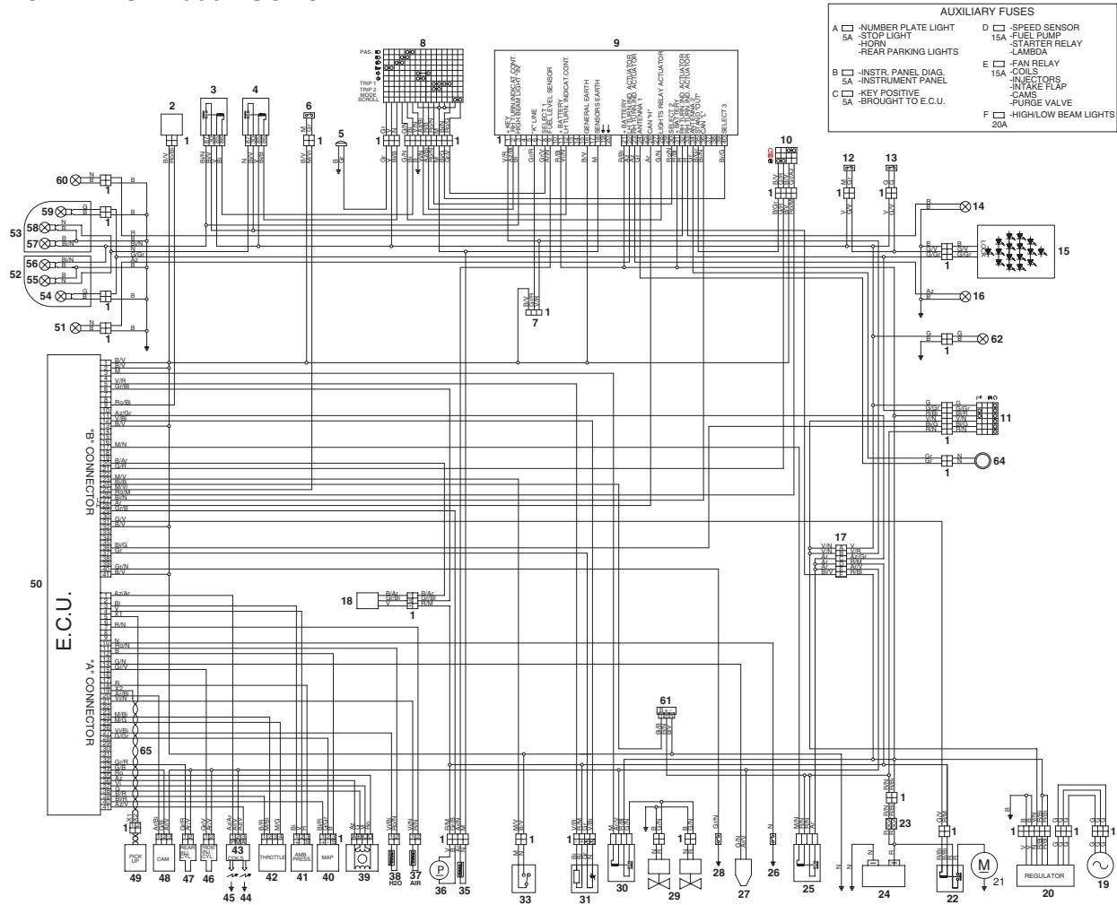
WIRING DIAGRAM RSV 1000 TUONO R
WIRING DIAGRAM KEY - RSV 1000 TUONO R
Thanks to ongoing technical updates and product-specific technical training, aprilia Authorised Network engineers are familiar with every detail of this vehicle and have the special equipment required for correct maintenance and repair.
A vehicle kept in sleek running order is a reliable vehicle. Pre-ride checks, proper maintenance at the recommended intervals and using aprilia Original Parts only are key factors!
To find contact information of the Authorised Dealer and/or Service Centre nearest you, please consult the Yellow Pages or the map provided at our web site :
www.aprilia.com
When you demand aprilia Original Parts, you are purchasing products that have been developed and tested as early as the vehicle design stage. aprilia Genuine Parts systematically undergo strict quality control procedures to ensure total reliability and long service life. aprilia s.p.a. wishes to thank its customers for the purchase of this vehicle.
Do not release oil, fuel, polluting substances and components into the environment.
Do not keep the engine running when not necessary.
Avoid disturbing noise.
Respect the environment.
- WARNING
- CAUTION
- TECHNICAL INFORMATION
- WARNING - PRECAUTIONS - GENERAL ADVICE
- VERSION:
- TABLE OF CONTENTS
- BASIC SAFETY RULES
- CLOTHING
- ACCESSORIES
- LOAD
- KEY
- INSTRUMENTS AND INDICATORS TABLE
- MULTIFUNCTION COMPUTER
- Controls
- TRIP 1 AND 2
- Mode
- Menu
- SETTINGS
- TIME SETTINGS
- GEAR SHIFT INDICATOR
- BACK LIGHTING
- CHANGE THE CODE
- CODE RECOVERY
- ° C / ° F
- Lap timer
- ENABLE LAP TIMER
- VIEW TIMES
- DELETE TIMES
- Lap time operation
- Diagnosis
- Language
- SERVICE INTERVAL
- ALARM DISPLAY
- CONTROLS ON THE LEFT SIDE OF THE HANDLEBAR
- IGNITION SWITCH
- STEERING LOCK
- OPERATION
- To lock the steering:
- UNLOCKING/LOCKING THE PASSENGER SET/SEAT COVER
- GLOVE/TOOL KIT COMPARTMENT
- The tool kit (1) includes:
- Luggage FIXING POINTS
- SPECIAL TOOLS OPT
- FUEL
- DO NOT DISPOSE OF FUEL IN THE ENVIRONMENT.
- KEEP AWAY FROM CHILDREN.
- To refuel, proceed as follows:
- After refuelling:
- BRAKE FLUID - RECOMMENDATIONS
- FRONT BRAKE
- CHECK
- TOPPING UP
- REAR BRAKE
- CLUTCH FLUID - RECOMMENDATIONS
- CLUTCH
- COOLANT
- TYRES
- MINIMUM TREAD DEPTH LIMIT (3):
- ENGINE OIL
- EXHAUST MUFFLER/EXHAUST SILENCER
- INSTRUCTIONS FOR USE
- GETTING ON AND OFF THE VEHICLE
- Risk of falling and overturning. Proceed with care.
- GETTING ON THE VEHICLE
- GETTING OFF THE VEHICLE
- PRE-RIDE CHECKS
- STARTING
- To leave:
- To shift down, proceed as follows:
- RUNNING-IN
- Keep to the following indications:
- STOPPING
- PARKING
- PLACING THE VEHICLE ON THE STAND
- SIDE STAND
- SUGGESTIONS TO PREVENT THEFT
- IMMOBILISER (if fitted)
- MAINTENANCE
- REGULAR SERVICE INTERVALS CHART
- OPERATIONS TO BE CARRIED OUT BY THE aprilia Authorised Dealer
- IDENTIFICATION DATA
- FRAME NUMBER
- ENGINE NUMBER
- JOINTS WITH CLICK CLAMPS AND WITH SCREW CLAMPS
- CLICK CLAMPS
- SCREW CLAMPS
- CHECKING AND TOPPING UP ENGINE OIL LEVEL
- CHANGING ENGINE OIL AND THE ENGINE OIL FILTER
- To change, proceed as follows:
- Drain plug (2) tightening torque: 15 Nm (1.5 kgm).
- CHANGING THE ENGINE OIL FILTER
- Never reuse a filter.
- CLEANING THE ENGINE OIL FILTER LOCATED ON THE TANK
- Engine oil filter (9) tightening torque: 30 Nm (3 kgm).
- Do not put additives or other substances into the oil.
- AIR FILTER
- DO NOT RELEASE POLLUTING PRODUCTS INTO THE ENVIRONMENT.
- REMOVAL
- REPLACEMENT
- POSITIONING THE VEHICLE ON THE REAR SUPPORT STAND OPT
- POSITIONING THE VEHICLE ON THE FRONT SUPPORT STAND OPT
- FRONT WHEEL
- DISASSEMBLY
- REASSEMBLY
- REAR WHEEL
- DRIVE CHAIN
- CHAIN SLACK INSPECTION
- CHAIN SLACK ADJUSTMENT
- Wheel nut (1) tightening torque: 120 Nm (12 kgm).
- CHECKING CHAIN AND SPROCKETS FOR WEAR
- CLEANING AND LUBRICATION
- REMOVING THE RIDER SEAT
- Screw (1) driving torque: 12 Nm (1.2 kgm).
- NOTE On refitting, insert the front tab of the seat into the corresponding seat.
- LIFTING THE FUEL TANK
- REMOVING THE SIDE FAIRINGS
- REMOVING THE SIDE PANELS
- REMOVING THE REAR-VIEW MIRRORS
- REMOVING THE SIDE STAND
- Driving torque of screws (11) and (13): 40 Nm (4 kgm).
- INSPECTING THE FRONT AND REAR SUSPENSIONS
- FRONT SUSPENSION
- SETTING THE FRONT FORK
- FORK
- STEERING DAMPER
- REAR SUSPENSION
- CHECKING THE BRAKE PADS FOR WEAR
- ADJUSTING THE THROTTLE TWISTGRIP
- If not, proceed as follows:
- SPARK PLUGS
- Key:
- Never attempt to adjust electrode gap.
- For the installation:
- CHECKING THE SIDE STAND
- Check for the following:
- The following occurs:
- BATTERY
- CLEANING AND CHECKING BATTERY TERMINALS AND LEAD CONNECTIONS
- If necessary, proceed as follows:
- REMOVING THE BATTERY
- Carefully read page 95 (BATTERY).
- CHECKING BATTERY FLUID LEVEL
- CHARGING THE BATTERY
- INSTALLING THE BATTERY
- LONG INACTIVITY OF THE BATTERY
- CHECKING THE SWITCHES
- REPLACING THE FUSES
- ARRANGEMENT OF 5-A AUXILIARY FUSES
- ARRANGEMENT OF 15-A AUXILIARY FUSES
- ARRANGEMENT OF 20-A AUXILIARY FUSES
- NOTE There are three spare fuses (G). ARRANGEMENT OF 30-A MAIN FUSES
- VERTICAL ADJUSTMENT OF THE HEADLIGHT BEAM
- To adjust the headlight beam:
- After the adjustment:
- TAPING OF THE HEADLIGHT
- BULBS
- REPLACING THE INSTRUMENT PANEL LED
- CHANGING THE HEADLIGHT BULBS
- Carefully read page 103 (BULBS).
- HIGH AND LOW BEAM BULBS
- Do not pull on the wires to extract the bulb connector.
- CHANGING THE FRONT AND REAR TURN INDICATOR BULBS
- REPLACING THE NUMBER PLATE LIGHT BULB
- TRANSPORT
- CLEANING
- Proceed as follows:
- AFTER STORAGE
- TECHNICAL DATA
- LUBRICANT CHART
- WIRING DIAGRAM KEY - RSV 1000 TUONO R
- www.aprilia.com
Brand : APRILIA
Model : RSV 1000 TUONO R
Category : Motorcycle