USER MANUAL SCARABEO 125 APRILIA
REEMPLACEMENT DES AMPOULES
DES CLIGNOTANTS DE DIRECTION 50
REEMPLACEMENT DES AMPOULES
DU FEU AVANT 51
REEMPLACEMENT DES AMPOULES
DU FEU ARRIERE 52
TRANSPORT 53
VIDANGE DU RESERVOIR DE CARBURANT. 53
NETTOYAGE 54
PERIODES DE LONGUE INACTIVITE 55
avant: 2 mm (USA 3 mm)
arrière: 2 mm (USA 3 mm)
POT/SILENCIEUX D'ECHAPPEMENT
DANGER
REEMPLACEMENT DES AMPOULES DU FEU AVANT
Lire attentivement page 50 (AMPOULES).
WECHSEL DER GLUHLAMPEN
IN DEN BLINKERN 50
AUSTAUSCH DER
SCHEINWERFERGLUHLAMPEN 51
AUSTAUSCH DER RÜCKLIGHTGLÜHLAMPEN... 52
TRANSPORT 53
ENTLEEREN DES KRAFTSTOFFTANKS. 53
REINIGUNG 54
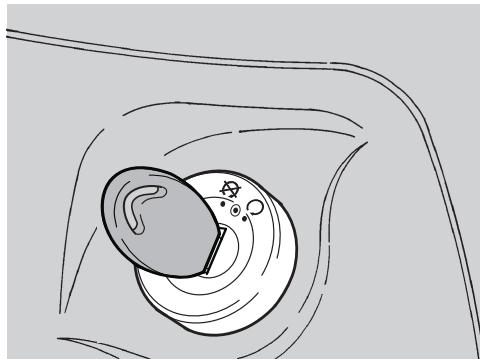
WICHTIG Den Schlüssel (3)
Porridge, a popular beverage made from the fruit of the pineapple. It is used to cure wounds and wounds in the hand.
Aflojar los tornillos (4).
Colocar el asiento (3) en la posicion deseada.
Ajustar los tornillos (4).

KIT HERRAMIENTAS
NoURTINATIANTIATIATIATIATIATIATIATIATIATIATIATIATIATIATIATIATIATIATIATIATIATIATIATIATIATIATIATIATIATIATIATIATIATIATIATIATIATIATIATIATIATIATIATIATIATIATIATIATIATIATI
First edition: February 2004
Reprint: September 2006/A
Produced and printed by:
VALLEY FORGE DECA
Ravenna, Modena, Torino
DECA S.r.l.
Registered Main Office
Via Vincenzo Giardini, 11
48022 Lugo (RA) - Italy -
Tel. 0545-216611
Fax 0545-216610
www.vftis.com
deca@vftis.spx.com
On behalf of:
Piaggio & C. S.p.A.
via G. Galilei, 1 - 30033 Noale (VE) - Italia
Tel. +39-041 58 29 111
Fax +39-041 44 10 54
www.aprilia.com
SAFETYWARNINGS
The symbols and warnings used throughout this manual have the following meanings:
Safety warning. This symbol attached to the vehicle or in the manual indicates a potential risk of personal injury. Non-compliance with the indications given in the messages preceded by this symbol may result in major risks for your and other people's safety and for the vehicle!
WARNING
Indicates a potential hazard which may result in serious injury or even death.
CAUTION
Indicates a potential hazard which may result in minor personal injury or damage to the vehicle.
CAUTION
The
word
"CAUTION" in this manual identifies important information or instructions.
The operations preceded by this symbol must be repeated on the opposite side of the vehicle.
Unless expressly indicated otherwise, reassembly is a reversal of the disassembly procedure.
The terms "right" and "left" are referred to the rider seated on the vehicle in the normal riding position.
WARNING - PRECAUTIONS - GENERAL ADVICE
Before starting the engine, carefully read this manual and in particular the section "SAFE DRIVE".
Your and other people's safety largely depends on your reflexes and agility, but there are other key factors, such as your knowledge of the vehicle's operation and condition, as well as of the basic rules of "SAFE RIDING". Becoming thoroughly familiar with vehicle is essential to mastering safe riding techniques in traffic.
CAUTION
This manual must be
considered as an integral part of the vehicle and must always accompany it, also in the event the vehicle is resold.
aprilia has carried out this manual with the maximum attention, in order to supply the user with correct and updated information. However, since aprilia constantly improves the design of its products, there may be slight discrepancies between the characteristics of your vehicle and those described in this manual.
For any clarification concerning the information contained in this manual, do not hesitate to contact your aprilia Authorised Dealer.
For control and repair operations not expressly described in this publication, for the purchase of aprilia genuine spare parts, accessories and other products, as well as for specific advice, contact exclusively aprilia Authorised Dealers and Service Centres, which guarantee prompt and accurate assistance.
Thank you for choosing aprilia. We wish you a nice ride.
All rights of electronic storage, reproduction and total or partial adaptation with any means reserved for all Countries.
CAUTION
Some countries
have statutory emission and noise control regulations in place requiring that motor vehicles undergo periodical inspections.
Users in these countries must:
- contact an aprilia Authorised Dealer to have the non-homologated components replaced with others homologated for use in the country in question;
have their vehicles inspected at the required intervals.
CAUTION
Soon after purchasing
the vehicle, write down the identification data indicated on the SPARE PARTS IDENTIFICATION LABEL in the table here below. The label is on the right upper tube of the frame; to read it, it is necessary to remove the central fairing, see page 41 (REMOVING THE CENTRAL FAIRING).
aprilia
SPARE PARTS IDENTIFICATION
YEAR
I.M.
| I | UK | A | P | SF | B | D | F | E | GR |
| NL | CH | DK | J | SGP | SLO | IL | ROK | MAL | RCH |
| HR | AUS | USA | BR | RSA | NZ | CDN | | | |
These data indicate:
- YEAR = year of manufacture (Y, 1, 2, ...);
- I.M. = modification code (A, B, C, ...);
- COUNTRY CODES = homologation country (I, UK, A, ...).
and are to be supplied to the aprilia Authorised Dealer as reference data for the purchase of spare parts or specific accessories of the model you have acquired.
Market versions are identified by the following symbols throughout the manual:
125 model 125 cu cm
250 model 250 cu cm
OPT optional
VERSION:
Italy
SGP
Singapore
UK United
SLO
Slovenia
Austria
IL
Israel
P Portugal
ROK
South Korea
SF Finland
MAL
Malaysia
B Belgium
RCH
Chile
Germany
HR Cre
Croatia
France
AUS Australia
Spain
USA United States of America
Greece
BR Brazil
NL Holland
RSA South Africa
CH Switzerland
NZ New Zealand
DK Denmark
CDN Canada
Japan
GENERAL SUMMARY
SAFETYWARNINGS 2
TECHNICAL INFORMATION 2
WARNING - PRECAUTIONS - GENERAL
ADVICE 2
GENERAL SUMMARY 4
BASIC SAFETY RULES 6
CLOTHING 8
ACCESSIONS 8
LOAD 9
ARRANGEMENT OF THE MAIN ELEMENTS... 10
LOCATION OF INSTRUMENTS/CONTROLS... 12
INSTRUMENTS AND INDICATORS 12
INSTRUMENTS AND INDICATORS TABLE 13
MAIN INDEPENDENT CONTROLS 14
CONTROLS ON LEFT HANDLEBAR. 14
CONTROLS ON RIGHT HANDLEBAR...... 14
IGNITION SWITCH 15
STEERING LOCK. 15
AUXILIARY EQUIPMENT 16
DIGITAL CLOCK 16
BAG HOOK. 16
ANTITHEFT HOOK 17
UNLOCKING/LOCKING THE SEAT. 17
GLOVE COMPARTMENT 18
ADJUSTABLE PASSENGER SEAT. 18
TOOLKIT 18
MAIN COMPONENTS 19
FUEL 19
LUBRICANTS 19
BRAKE FLUID - recommendations 20
DISC BRAKES 20
COOLANT 22
TYRES 24
EXHAUST MUFFLER/EXHAUST
SILENCER 25
INSTRUCTIONS FOR USE 26
PRE-RIDE CHECKS CHART 26
STARTING 27
MOVING OFF AND RIDING 29
RUNNING-IN 31
STOPPING 31
PARKING 31
PLACING THE VEHICLE ON THE STAND. 32
SUGGESTIONS TO PREVENT THEFT 33
MAINTENANCE 33
SCHEDULED MAINTENANCE CHART. 34
IDENTIFICATION DATA 36
CHECKING AND TOPPING UP ENGINE OIL LEVEL 37
AIR FILTER 38
CHECKING THE BRAKE PADS FOR WEAR 39
INSPECTING THE FRONT AND REAR SUSPENSIONS 40
ADJUSTING THE REAR SUSPENSION..... 40
REMOVING THE CENTRAL INSPECTION COVER. 41
REMOVING THE CENTRAL FAIRING 41
REMOVING THE FRONT COVER 42
REMOVING THE FRONT INSPECTION COVER. 42
IDLINGADJUSTMENT 43
ADJUSTING THE THROTTLE TWISTGRIP 43
SPARK PLUG 44
BATTERY 45
LONG INACTIVITY OF THE BATTERY. 45
EXTRACTING THE BATTERY CASE. 46
CHECKING AND CLEANING THE TERMINALS 46
REMOVING THE BATTERY 46
CHECKING BATTERY FLUID LEVEL 47
CHARGING THE BATTERY 47
INSTALLING THE BATTERY 47
CHANGING THE FUSES 48
CHECKING THE SWITCHES 49
VERTICAL ADJUSTMENT OF THE HEADLIGHT BEAM. 49
BULBS. 50
CHANGING THE TURN INDICATOR BULBS. 50
CHANGING THE HEADLIGHT BULBS .... 51
CHANGING THE TAIL LIGHT BULBS. 52
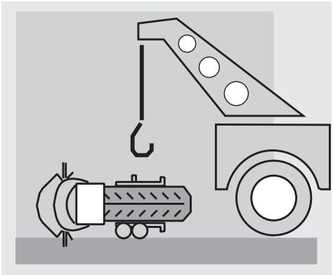
TRANSPORT 53
DRAINING THE FUEL TANK 53
CLEANING 54
LONG PERIODS OF INACTIVITY 55
TECHNICAL DATA 56
LUBRICANT CHART 59
WIRING DIAGRAM - Scarabeo 125 60
KEY TO WIRING DIAGRAM - Scarabeo 125 61
WIRING DIAGRAM - Scarabeo 250 62
KEY TO WIRING DIAGRAM - Scarabeo 250 63
AUTHORISED DEALERS AND SERVICE CENTRES 64

safe drive
BASIC SAFETY RULES
To drive the vehicle, you must satisfy certain legal requirements (driving licence, minimum age limit, psychophysical fitness, insurance, vehicle licence tax, vehicle registration, number plate, etc.).
Begin to familiarise yourself with the vehicle by riding in low traffic areas and/or private ground.
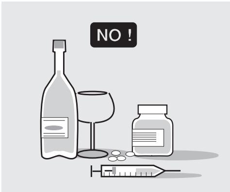
Certain prescribed medicines, alcohol, drugs and psychotropic substances will affect your riding, thereby increasing the risk of an accident. Be sure that you are in good psychophysical conditions and fit for driving and pay particular attention to physical weariness and drowsiness.
Most road accidents are caused by inexperienced riders.
NEVER lend your vehicle to a beginner and make sure any person borrowing your vehicle fills the legal requirements for driving.
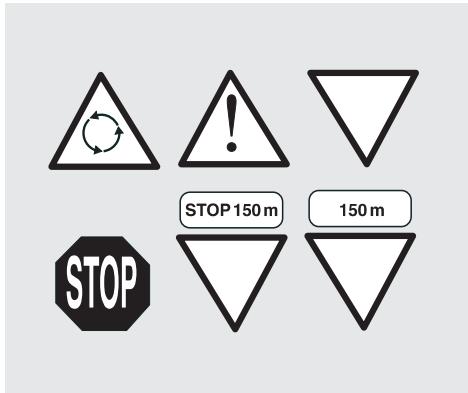
Strictly observe all posted signs and national and local road regulations.
Avoid any sudden or risky manoeuvres that may endanger your and other people's safety (for example: wheelies, speeding, etc.), and adjust your riding style to road surface conditions, visibility, etc.
Avoid obstacles that could damage the vehicle or make you lose control of the vehicle.
Avoid riding in the slipstream of vehicles ahead in order to increase your speed.
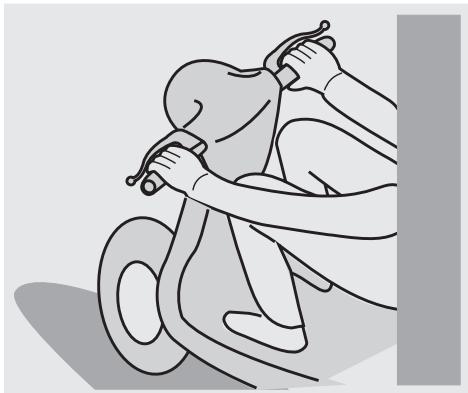
WARNING
Always hold the handlebars with both hands and keep both feet on the footpegs (or on the rider's footboards), in the correct riding position.
Do not stand up or stretch your limbs while riding.
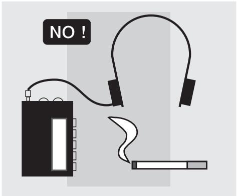
The driver should pay attention and avoid distractions caused by people, things and movements (never smoke, eat, drink, read, etc.) while driving.
Use only the specified fuels and lubricants indicated in the "LUBRICANT CHART" and check oil, fuel and coolant levels at regular intervals.
If the vehicle has been involved in an accident, check the control levers, pipes and hoses, wires, the braking system and key components for damage.
If necessary, have the vehicle inspected by an aprilia Authorised Dealer who should carefully check the frame, handlebars, suspensions, safety parts and all the devices that you cannot check by yourself.
Remember to report any malfunction to the technicians and/or mechanics to facilitate their work.
Never use the vehicle when the amount of damage it has suffered makes it unsafe to ride.
Never change the position, inclination or colour of: number plate, turn indicators, lights and horns.
Any modification made to the vehicle will invalidate the warranty.
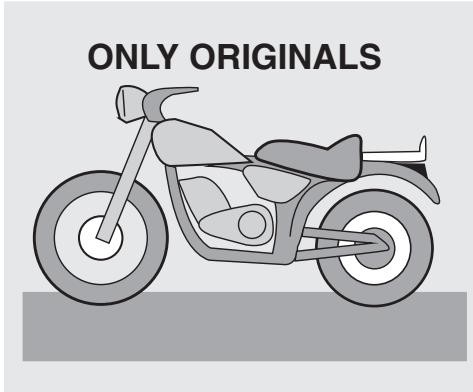
Making any modifications to the vehicle and/or removing the original components can adversely affect vehicle performance and safety or make it illegal to ride.
Observe applicable law and all national and local regulations concerning vehicle equipment.
In particular, avoid any modifications apt to enhance performance or alter the vehicle's original specifications.
Never race with other vehicles.
Do not ride off road.
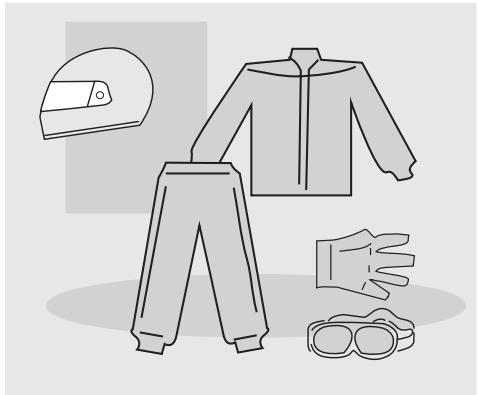
CLOTHING
Always wear and fasten your helmet correctly before moving off. Make sure your helmet complies with applicable regulations, is not damaged, is the right size and keep the visor clean.
Wear protective clothing, preferably bright and/or reflective clothing. This will ensure you are easily seen by other road users and reduce the risk of an accident, besides affording improved protection in the event of a fall.
Wear tight-fitting clothing fastened at the wrists and ankles; make sure no strings, belts and ties are hanging loose; make sure no items of clothing or other objects can distract you or become entangled with moving parts or with the handlebars.
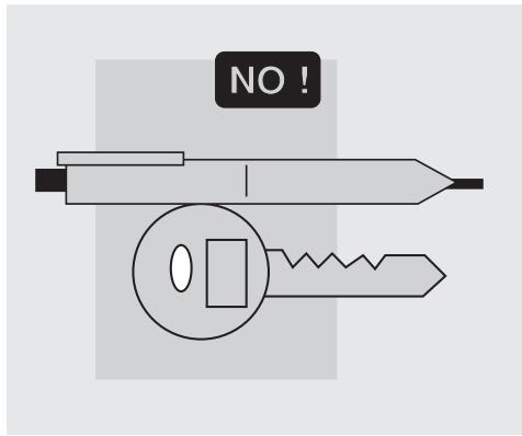
Do not ride with sharp or pointed objects in your pockets as they might cause injury in the event of a fall (this includes keys, pens, glass vials, etc. - note that the same applies to your passenger).
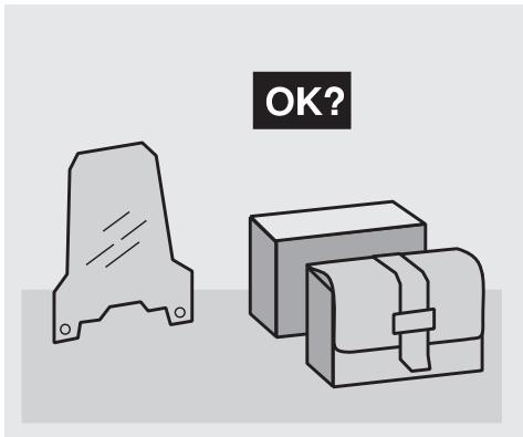
ACCESSORIES
The owner of the vehicle is responsible for the choice, installation and use of any accessory.
Any accessories installed must not cover the horns or lights or impair their operation, restrict suspension travel and steering angle, impair the operation of any vehicle controls or affect ground clearance or bank angle in a bend.
Avoid using accessories that may hamper access to vehicle controls, as this can slow down your reaction in an emergency.
Large fairings and windshields may affect the vehicle's aerodynamics and make it unstable, especially at high speeds.
Make sure any accessories installed are fastened securely to the vehicle and will not affect safety during riding.
Do not install or modify any electric devices in such a manner as to exceed vehicle capacity, as this may lead to a power shortage or failure causing the engine to stop suddenly or rendering the horn and lights inoperative.
aprilia recommends the use of genuine accessories (aprilia genuine accessories).
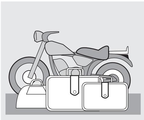
LOAD
Be careful not to overload the vehicle with exceeding luggage. Place your luggage as close as possible to the centre of gravity of the vehicle and make sure its weight is evenly distributed across both sides of the vehicle to keep it stable. Make sure that the luggage is firmly secured to the vehicle, especially before long trips.
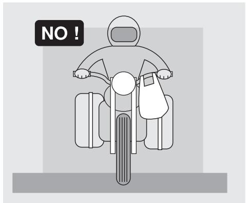
Avoid fixing bulky, heavy and/or dangerous objects to the handlebars, mudguards and forks - this could slow down the vehicle's response in turns and would inevitably affect handling.
Do not secure bulky bags to the vehicle sides, as they could hit people or obstacles when riding, resulting in loss of control.
Do not carry any luggage unless firmly secured to the vehicle.
Do not carry bags which protrude too much from the luggage-rack or which cover the lights, horn or indicators.
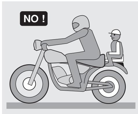
Do not carry animals or children on the glove compartment or on the luggage rack.
Do not exceed the maximum load capacity of each luggage rack.
The overloaded vehicle will become unstable and handle poorly.
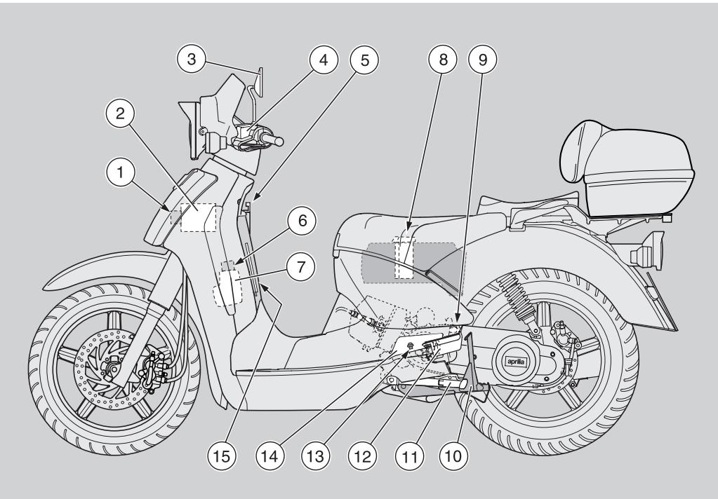
KEY
1) Fuse carrier
2) Battery
3) Left rear-view mirror
4) Rear brake fluid reservoir
5) Bag hook
6) Coolant expansion tank plug
7) Expansion tank
8) Air filter
9) Antitheft hook (for the aprilia "Body-Guard" shielded cable OPT)
10) Centre stand
11) Side stand
12) Left passenger footpeg
13) Engine oil filler plug
14) Engine oil filler plug cover
15) Front inspection cover
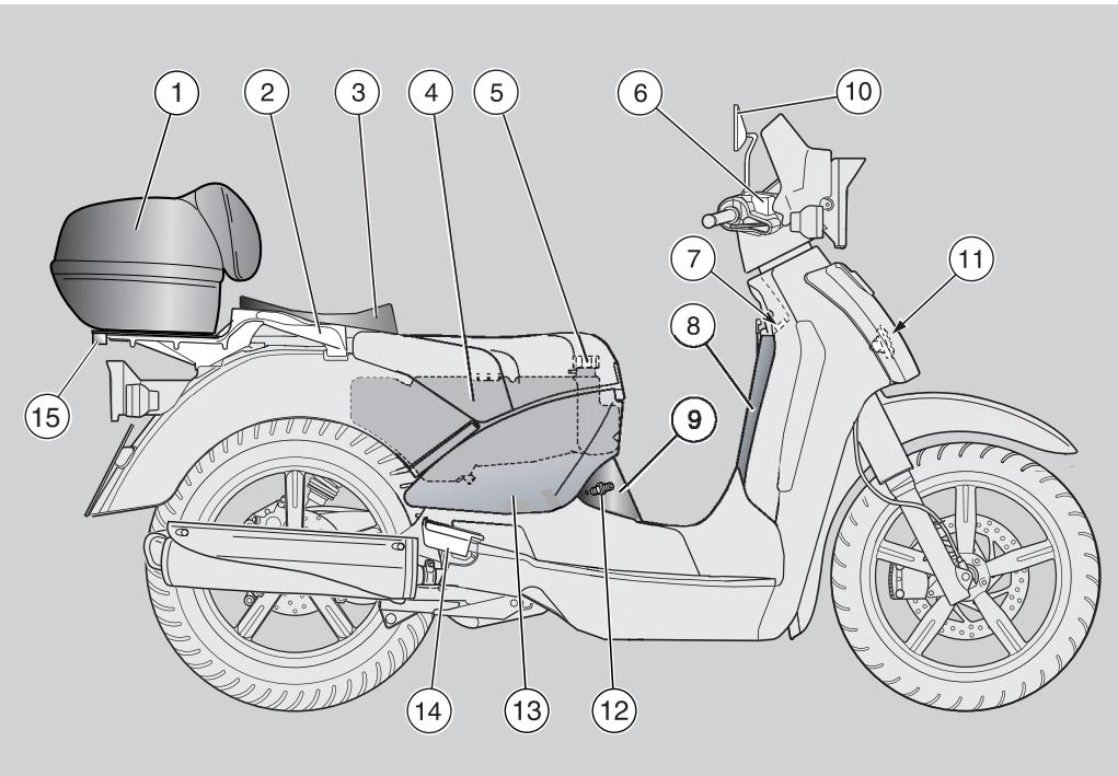
KEY
1) Crash helmet case
2) Passenger grab handle
3) Passenger seat
4) Fuel tank
5) Fuel tank filler plug
6) Front brake fluid reservoir
7) Ignition switch/steering lock /seat unlocking
8) Glove compartment
9) Centre inspection cover
10) Right rear-view mirror
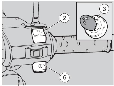
11) Warning horn
12) Spark plug
13) Central fairing
14) Right passenger footpeg
15) Case opening block
LOCATION OF INSTRUMENTS/CONTROLS
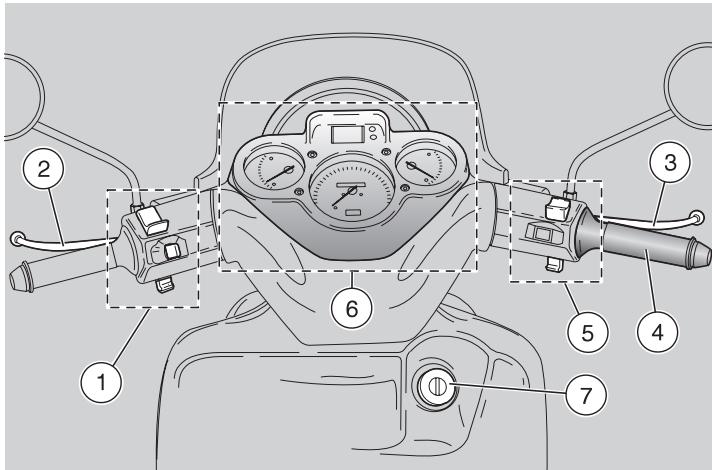
KEY
1) Electrical controls on the left side of the handlebar
2) Combined brake lever (front + rear)
3) Front brake lever
4) Throttle grip
5) Electrical controls on the right side of the handlebar
6) INSTRUMENTS AND INDICATORS
7) Ignition switch/steering lock (○- - - ) /seat unlocking (OPEN)
INSTRUMENTS AND INDICATORS
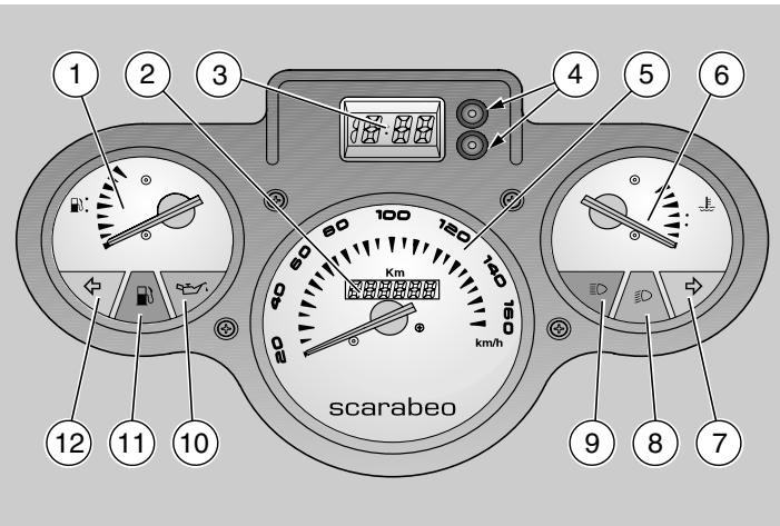
KEY
1) Fuel level indicator (B)
2) Total kilometres odometer
3) Digital clock
4) Digital clock function and setting push buttons
5) Speedometer
6) Coolant temperature indicator (
7) Green right direction indicator warning light ()
8) Green low beam warning light (D)
9) Blue high beam warning light (D)
10) Red engine oil pressure warning light (
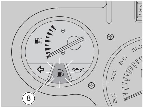
11) Amber low fuel light (B)
12) Green left direction indicator warning light (Φ)
INSTRUMENTS AND INDICATORS TABLE
| Description | Function |
| Right direction indicator warning light ➔ | It blinks when the right direction indicator is on. |
| Left direction indicator warning light ➔ | It blinks when the left direction indicator is on. |
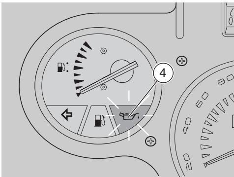
| Engine oil pressure warning light ➔ | Comes on when the ignition switch is set to "○" with the engine stopped as a lamp test. If during this phase the lamp does not turn on, it must be replaced.
The warning light must go off when the engine is running.
A CAUTION If the light stays on or comes on during normal operation, it means that oil pressure in the circuit is too low. Stop the engine immediately and contact an aprilia Authorised dealer. |
| Total kilometres odometer | It indicates the total number of kilometres covered. |
| Speedometer | Indicates road speed. |
| High beam warning light ➔ | Comes on when the headlight high beam is on or when you flash the high beam (PASSING). |
| Low beam warning light b | It comes on when the headlight is in low beam position. |
| Low fuel warning light ➔ | It comes on when the quantity of fuel left in the tank is 2 l. |
| Fuel level indicator ➔ | It indicates the approximate fuel level in the tank.
When the pointer reaches the red area, the quantity of fuel left in the tank is 2 l. When the light comes on, refuel as soon as possible, see page 19 (FUEL). |
| Digital clock | Hour, date and seconds can be shown on the display, see page 16 (DIGITAL CLOCK). |
| Coolant temperature indicator ➔ | It indicates the approximate temperature of the coolant in the engine.
When the pointer starts moving beyond level "MIN", the temperature is sufficient for driving the vehicle.
The normal running temperature range is indicated by the central area of the scale.
If the pointer reaches the red area, stop the engine and check the coolant level, see page 22 (COOLANT).
A CAUTION Exceeding the maximum coolant temperature allowed (red "max" area) may lead to severe engine damage. |
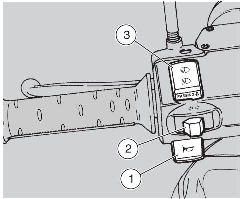
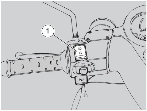
CONTROLS ON LEFT HANDLEBAR
CAUTION The electric
components only operate when the ignition switch is in the "O" position.
1) HORN BUTTON (▶)
Press this button to operate the horn.
2) TURN INDICATOR SWITCH (↔ ⇌)
To indicate the turn to the left, move the switch to the left; to indicate the turn to the right, move the switch to the right. Press the switch to cancel the signal.
3) DIMMER SWITCH (D - D) / HIGH BEAM FLASHER PUSH-BUTION (PASSING )
if the dimmer switch is in position “ D ”, the high beam comes on, while if it is in position “ D ”, the low beam comes on.
The high beam flasher is operated by pressing the dimmer switch to position (PASSING ).
CAUTION Release the dimmer switch to turn off the high beam.
CONTROLS HANDLEBAR
ON
RIGHT
CAUTION
The
electric
components only operate when the ignition switch is in the "O" position.
1) START PUSH-BUTION (③)
When the starter button “ () “ is pressed, the starter motor will crank the engine. For the starting procedure, see page 27 (STARTING).
2) ENGINE STOP SWITCH ( -)
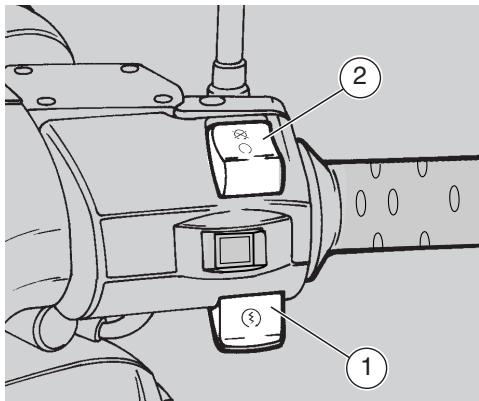
WARNING
Do not operate the engine stop switch "O - 8" while riding.
This switch serves as a safety or emergency switch.
With the switch in position "O", it is possible to start the engine; the engine can be stopped by moving the switch to position "Q".
CAUTION
With the engine stopped and the ignition switch in position "O", the battery may run flat.
When the vehicle has come to a standstill and you have stopped the engine, set the ignition switch to position ^
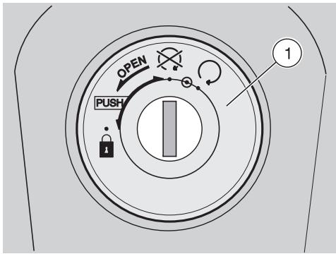
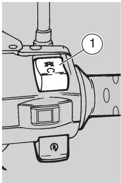
IGNITION SWITCH
The ignition switch (1) is positioned on the right side of the steering head.
CAUTION
The key (2) operates
the ignition switch / steering lock, the seat lock and the glove compartment lock.
Two keys are supplied together with the vehicle (one spare key).
CAUTION
Store the spare key
in a safe place (other than the vehicle).
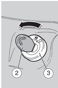
STEERING LOCK
WARNING
Never turn the key to position "B" when riding, or you will lose control of the vehicle.
OPERATION
To lock the steering:
Turn the handlebar fully to the left.
Turn the key (2) to position "X".
CAUTION
The simple turning of the key, without any pressure, operates the seat lock and not the steering lock.
CAUTION
Turn the key and
steer the handlebar at the same time.
Press the key (2) and turn it anticlockwise (to the left), then steer the handlebar slowly, until the key (2) reaches position "
Extract the key.
| Position | Function | Key removal |
| Steering lock | The steering is locked. It is not possible to start the engine or switch on the lights. | It is possible to remove the key. |
| × | Neither the engine, nor the lights will operate. | It is possible to remove the key. |
| ○ | The engine and the lights can be operated. | It is not possible to remove the key. |

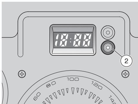
DIGITAL CLOCK
Function description:
Normal display: hours and minutes.
Date display: press the push button (1) once to display month and day.
Second display: press the push button (1) twice to display the seconds.
CAUTION Have clock battery changed at an aprilia Authorised Dealer.
Setting:
Press the push button (2) once: date and time will be displayed alternately.
Month: press the push button (2) again and the month will be displayed on the left (the rest disappears). Press the push button (1) to set the desired month.
Day: press the push button (2) again and the day will be displayed on the right.
Press the push button (1) to set the desired day.
Hour: press the push button (2) again and the time will be displayed on the left with letter "A" or "P" ( A = AM , P = PM ).
Press the push button (1) to set the desired time.
Minutes: press the push button (2) again and the minutes will be displayed on the right.
Press the push button (1) to set the desired minutes.
Now the clock is set.
Press the push button (2) and then the push button (1), again to return to normal operation.
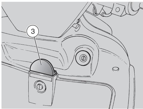
BAG HOOK
WARNING
Do not hang excessively bulky bags or parcels to the hook, as this may seriously compromise the manoeuvrability of the vehicle or the movement of your feet.
The bag hook (3) is positioned on the front part of the inner shield.
Maximum allowed weight: 1.5kg
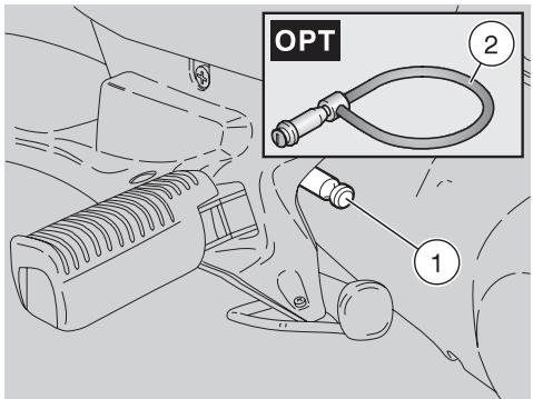
ANTITHEFT HOOK
The antitheft hook ( 1) is positioned on the left side of the vehicle, near the passenger footrest.
To prevent the vehicle from being stolen, it is advisable to secure it with the aprilia "Body-Guard" shielded cable OPT (2), available at any aprilia Authorised Dealer.
CAUTION
Do not use the hook to lift the vehicle or for any purpose other than securing the vehicle once it has been parked.
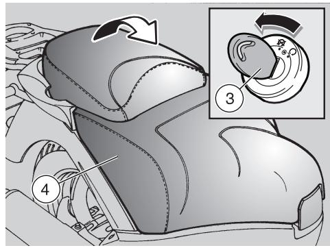
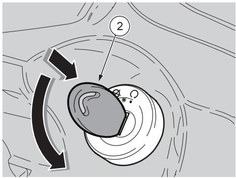
UNLOCKING/LOCKING THE SEAT
OPERATION
To unlock the seat, proceed as follows:
Position the vehicle on the centre stand.
Insert the key in the ignition switch / steering lock.
CAUTION
Turn the key (3)
without pressing it.
Turn the key (3) anticlockwise until you hear the snap that indicates that the lock is open.
Turn the key back to position "X".
Raise the seat (4).
To lock the seat, lower and press it (without exerting too much pressure), thus making the lock snap shut.
WARNING
Before leaving, make sure that the seat is properly locked.
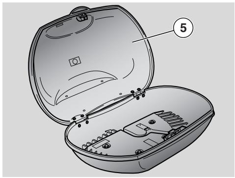
THE CRASH HELMET CASE
Insert the key in the helmet case lock.
Turn the key counter clockwise.
Lift the helmet case cover (5).
To lock the helmet case cover, lower and press it (without exerting too much pressure), thus making the lock snap shut.
WARNING
Make sure the helmet case cover is locked securely before riding.
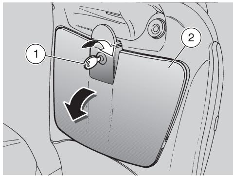
GLOVE COMPARTMENT
It is placed under the handlebar, on the inner part of the shield. To reach it:
Insert the key (1) in the lock.
Turn the key clockwise, pull it and open the door (2).
CAUTION
Before locking the door, make sure that you have not left the key in the glove compartment.
To lock the door (2), raise and press it. It is not necessary to use the key.
Maximum allowed weight: 1.5kg
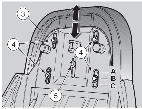
ADJUSTABLE PASSENGER SEAT
The passenger seat (3) can be adjusted longitudinally in three different positions:
- completely forward (A);
standard (B);
- completely backward (C).
Adjust as follows:
Raise the seat, see page 17 (UNLOCKING/LOCKING THE SEAT).
CAUTION
Do not adjust the special screw (5) for any reason whatsoever. Tampering with this screw is extremely dangerous and jeopardises the vehicle safety features.
Loosen the screws (4).
Move the seat (3) to the desired position.
Tighten the screws (4).
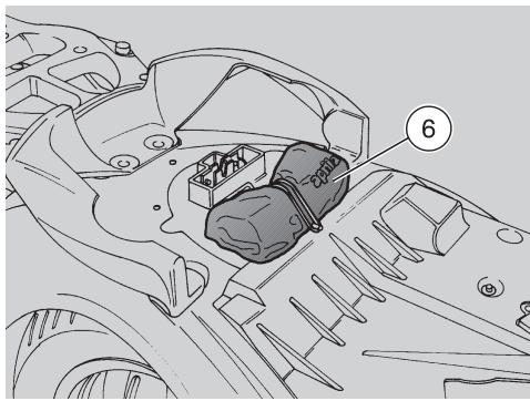
The tool kit (6) is fixed in the appropriate compartment under the seat.
Raise the seat, see page 17 (UNLOCKING/LOCKING THE SEAT).
The tool kit includes:
- tool case;
-screwdriver,“Fiat"-type l=128;
- screwdriver handle;
- 3 mm Allen wrench;
- 4 mm Allen wrench;
- shock absorber pin wrench;
- 16x140 mm spark plug spanner with 12 mm socket and seal;
- spark plug spanner extension:
- 8x120 mm rod.
- 45 mm cross-headed screwdriver
FUEL
WARNING
The fuel used in internal combustion engines is highly flammable and can become explosive under particular conditions. It is important to refuel and service the vehicle in a well-ventilated area, with the engine off. Do not smoke while refuelling or near fuel vapours, in any case avoid contact with naked flames, sparks and any other heat source or source of ignition to prevent fires or explosion.
Avoid spilling fuel, as it may ignite when in contact with hot engine parts. In the event of accidental spillage, make sure that the area has completely dried before starting the engine.
Never fill the tank to the rim, as fuel expands from heat and when left under direct sunlight.
Tighten the filler plug securely after refuelling. Avoid contact with skin, do not inhale fuel vapours; do not swallow fuel or transfer it between different receptacles using a hose.
DO NOT RELEASE FUEL INTO THE ENVIRONMENT.
KEEP AWAY FROM CHILDREN.
Use only premium grade leaded petrol (4 Stars UK) or unleaded petrol with 95 RON and 85 MON octane rating minimum.
TANK CAPACITY
(reserve included): 8.9 l
TANK RESERVE: 2 l
To reach the filler plug, proceed as follows:
Raise the seat, see page 17 (UNLOCKING/LOCKING THE SEAT).
Unscrew the filler plug (1).
LUBRICANTS
WARNING
Prolonged or repeated contact with oil may cause severe skin damage. Wash your hands carefully after handling engine oil.
Wear latex gloves during servicing. KEEP AWAY FROM CHILDREN.
DO NOT DISPOSE OF OIL IN THE ENVIRONMENT
CAUTION
Proceed with care.
Do not spill the oil!
Take care not to smear any component, the area in which you are working and the surrounding area. Carefully remove any trace of oil. In case of leakage or malfunctions, contact an aprilia Authorised Dealer.
Transmission fluid
Have the transmission fluid level checked every 6000km (3750 mi).
Have the transmission fluid changed after the first 1000km (625 mi) and then every 24000km (15000 mi).
Have inspection and replacement carried out by an aprilia Authorised Dealer.
ENGINE OIL
Periodically check the engine oil level, see page 37 (CHECKING AND TOPPING UP ENGINE OIL LEVEL)
CAUTION Use oil with
specifications 5/W 40, see page 59 (LUBRICANT CHART).
CAUTION
When topping up the engine oil, never exceed the "MAX" level.
It is necessary to have the engine oil changed after the first 1000km (625 mi) and successively:
- every 6000 km (3750 mi) have the engine oil changed
periodically check engine oil level/top up.
Have engine oil changed at an aprilia Authorised dealer.
BRAKE FLUID - recommendations
CAUTION This vehicle is fitted with front and rear disc brakes. Each braking system is operated by an independent hydraulic circuit.
The following information applies to both braking systems.
WARNING
Sudden changes in brake lever play or a spongy feel of the lever may indicate problems with the hydraulic system. If in doubt about the braking efficiency of your bike or if you are not able to perform routine checks, contact an aprilia Authorised dealer.
WARNING
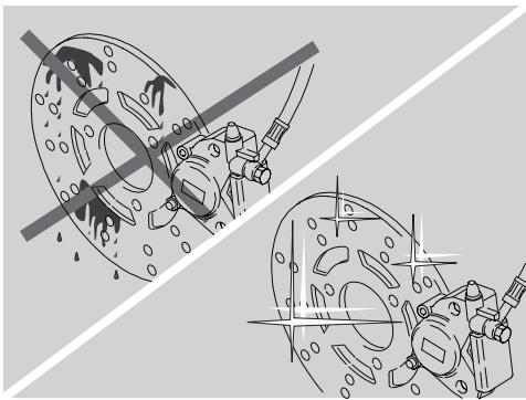
Pay special attention to the brake disc and friction material, making sure that they are neither dirty nor oily, especially after maintenance operations or inspections.
Make sure the brake hose is not twisted or worn.
KEEP AWAY FROM CHILDREN.
DO NOT RELEASE INTO THE ENVIRONMENT.
DISC BRAKES
WARNING
The brakes are critical to your safety and must always be kept in sleek running order. Check the brakes before each ride.
A dirty disc will soil the pads, leading to loss of braking efficiency. Dirty pads must be replaced, while dirty discs must be cleaned with a high-quality degreaser.
Have brake fluid changed at an aprilia Authorised dealer every two years.

CAUTION
This vehicle is fitted
with front and rear disc brakes. Each braking system is operated by an independent hydraulic circuit.
The following information applies to both braking systems.
Brake fluid level decreases gradually as the brake pads wear down.
The brake reservoirs are positioned on the handlebar, near the brake lever couplings.
Periodically check the brake fluid level in the reservoirs, see on the side (CHECK) and the wear of the pads, see page 39 (CHECKING THE BRAKE PADS FOR WEAR).

WARNING
Do not use the vehicle if the braking system is leaking fluid.
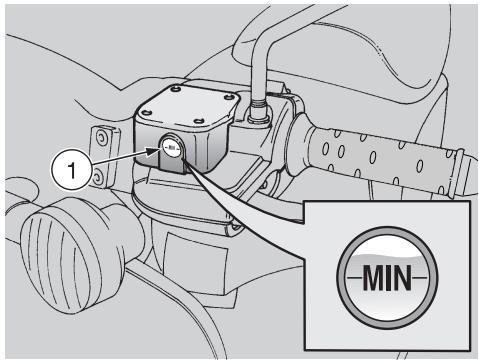
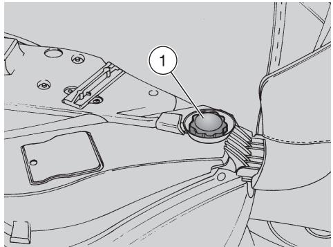
CHECK
To check the brake fluid level, proceed as follows:
CAUTION
Position the vehicle
on firm and flat ground.
Position the vehicle on the centre stand.
Remove turn indicator plastic protections.
- Rotate the handlebar, so that the fluid contained in the brake reservoir is parallel to the "MIN" mark stamped on the glass gauge (1).
- Make sure that the fluid contained in the reservoir exceeds the "MIN" mark stamped on the glass gauge (1).
MIN = minimum level.
If the fluid is below the "MIN" mark:
CAUTION
Brake fluid level decreases as the brake pads wear down.
- Check the brake pads for wear, see page 39 (CHECKING THE BRAKE PADS FOR WEAR) and brake disc.
If the pads and/or the disc do not need replacing:
Contact an aprilia Authorised Dealer, who will provide for topping up.
CAUTION
Check the brake for proper operation.
When the brake lever has exceeding travel or if you notice a loss of braking, contact an aprilia Authorised Dealer.
The braking system may need bleeding.
COOLANT
CAUTION
Do not ride when coolant is below the minimum level MIN.
Periodically check the coolant level and every time after long trips; have the coolant changed by an aprilia Authorised Dealer every 2 years.
WARNING
Coolant is toxic when ingested. Contact with eyes or skin may cause irritation.
In the event of contact with eyes or skin, rinse repeatedly with abundant water and seek medical advice. In the event of ingestion, induce vomiting, rinse mouth and throat with abundant water and seek medical advice immediately.
DO NOT RELEASE INTO THE ENVIRONMENT.
KEEP AWAY FROM CHILDREN.
Take care not to spill coolant onto hot engine parts. It may ignite and produce invisible flames.
Wear latex gloves during servicing.
Have the coolant changed at an aprilia Authorised Dealer.

Coolant mixture is a 50% solution of water and antifreeze.
This is the ideal solution for most operating temperatures and provides good corrosion protection.
This solution is also suited to the warm season, as the mixture is less prone to evaporative loss and will reduce the need for top-ups.
In addition, less water evaporation means fewer mineral salts depositing in the radiator, which helps preserve the efficiency of the cooling system.
When temperature drops below zero degrees centigrade, check the cooling system frequently and add more antifreeze (up to 60% maximum) to the solution.
Use distilled water in the coolant mixture. Tap water will damage the engine.
WARNING
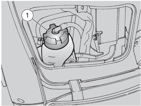
Do not remove the expansion tank plug (1) when the engine is hot, since coolant is very hot and under pressure. Contact with skin or clothes, may cause severe scalding and/or damage.
CHECKING AND TOPPING UP
WARNING
Wait for the engine to cool down before checking or topping up coolant level.
Stop the engine and wait until it has cooled down.
CAUTION Position the vehicle on firm and flat ground.
Remove the front inspection cover, see page 42 (REMOVING THE FRONT INSPECTION COVER).
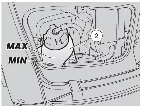
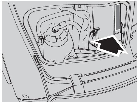
- Make sure that the level of the fluid contained in the expansion tank (2) is included between the "MIN" and "MAX" marks.
MIN = minimum level.
MAX = maximum level
If not so:
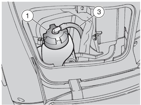
Loosen the filler plug (1) (by turning it anticlockwise by two turns), without removing it.
Wait a few seconds in order to release any residual pressure.
CAUTION A breather pipe (3) is connected to the plug (1). Neither force, nor disconnect the breather pipe (3).
Unscrew and remove the cap (1).
WARNING
Coolant is toxic when ingested. Contact with eyes or skin may cause irritation.
Do not put your fingers or any other object into the filler opening in order to ensure that there is coolant.

CAUTION
Never top up beyond the "MAX" level mark or coolant will leak out when the engine is running.
Top up with coolant, see page 59 (LUBRICANT CHART) up to just below the "MAX" mark.
Refit the filler plug (1).
CAUTION
If coolant level drops too quickly or the tank is empty, check the cooling circuit for leaks. Have the repair carried out at an aprilia Authorised dealer.
Refit the front inspection cover, see page 42 (REMOVING THE FRONT INSPECTION COVER).
TYRES
This vehicle is equipped with tubeless tyres.
WARNING
Periodically check the tyre inflation pressure at room temperature, see page 56 (TECHNICAL DATA).
Measuring pressure on hot tyres will lead to inaccurate measurement. It is especially important to measure tyre pressure before and after a long trip.
Overinflated tyres will not absorb bumps when riding on rough road surfaces and resulting vibration is transferred through the handlebar, giving a harsh ride and reducing tyre grip especially during cornering.
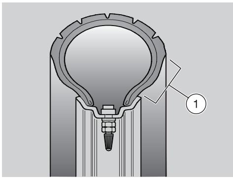
Conversely, underinflation will put more stress on the sidewalls (1) and the tyre may slip on the rim or even come off the rim, leading to loss of control.
The tyres could come off the rims under harsh braking.
Finally, the vehicle could skid during cornering.
Inspect tyre surface condition and check for wear, as worn tyres lead to poor road holding and handling.
Some of the tyres approved for this vehicle are equipped with wear indicators.
There are several kinds of wear indicators.
For more information on how to check the tyres for wear, contact your Dealer.
Visually inspect the tyres for wear and have them changed if worn.
Old tyres, even if not completely worn down, may become hard and provide poor grip.
In this case, have the tyres changed.
Have a tyre changed when worn or punctured, if the puncture in the tread is larger than 5mm
Have the wheels balanced after each tyre repair.
Use only tyres in the size suggested by aprilia, see page 56 (TECHNICAL DATA).
Do not install tube tyres on tubeless tyre rims or vice versa.
Always check that the caps are in place on the valves, or the tyres may deflate suddenly.
Tyre replacement and repair, as well as wheel servicing and balancing are delicate operations. They should be carried out using adequate tools and are best left to experienced mechanics.
Have your tyres and wheels serviced at an aprilia Authorised Dealer or a specialised tyre repairer.
New tyres may be coated with an oily film: ride carefully until covering several kilometres. Never apply nonspecific products to the tyres.

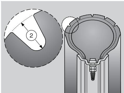
MINIMUM RECOMMENDED TREAD DEPTH (2)
front: 2 mm (USA 3 mm)
rear: 2 mm (USA 3 mm)
EXHAUST MUFFLER/EXHAUST SILENCER

WARNING
Tampering with the noise control system is prohibited.
Owners are warned that the law may forbid:
- The removal or disconnection of any device or element of design incorporated into any new vehicle to limit the noise emissions before its sale or delivery to the final purchaser or while it is in use except if carried out for maintenance, repair or replacement purposes; and
- the use of the vehicle after such device or element of design has been removed or rendered inoperative by any person.
Check the exhaust muffler/silencer and the silencer pipes, making sure that they show no traces of rust or holes and that the exhaust system is operating properly.
If the exhaust system noise increases, contact an aprilia Authorised Dealerimmediately.
INSTRUCTIONS FOR USE
WARNING
Check the vehicle before each ride to ensure safe riding. (See the PRE-RIDE CHECKS CHART on the side). Failure to perform these checks may lead to severe personal injury or vehicle damage.
If you have any doubts on the operation of the vehicle controls or believe that any vehicle components might be faulty, do not hesitate to contact an aprilia Authorised Dealer.
A quick pre-ride check takes just a few minutes and greatly improves your safety.
PRE-RIDE CHECKS CHART
| Part | Check | Page |
| Front and rear disc brakes | Check for proper operation, check lever free play, fluid level and check for leaks. Check the wear of the pads and noise reducing plates (at the rear only). Top up brake fluid level, if necessary. | 20, 39 |
| Brake levers | Make sure that they work smoothly. If necessary, lubricate the joints. | - |
| Throttle | Check for smooth operation; throttle should snap fully open and closed at all positions of the steering. Adjust and/or lubricate as required. | 43 |
| Wheels / tyres | Check tyre surface, inflation pressure. Check for wear or damage. | 24 |
| Steering | Steering should rotate smoothly and evenly. There should be no play or looseness. | - |
| Side stand and centre stand | Make sure that they work smoothly and that the spring tension brings them back to their normal position. Lubricate joints and connections, if necessary. | - |
| Fastening elements | Make sure that the fastening elements are not loose. Adjust or tighten as required. | - |
| Fuel tank | Check fuel level and top up, if necessary. Make sure there are no leaks or obstacles in the circuit. Make sure the filler plug is tightened securely. | 19, 53 |
| Coolant | Coolant level in the expansion tank must be between the "MIN" and "MAX" marks. | 22, 23 |
| Engine stop switch (○-○) | Make sure that it operates correctly. | 14 |
| Lights, warning lights, horn and electrical devices | Check the proper operation of the acoustic and visual devices. Change the bulbs or repair if faulty. | 45 – 52 |
STARTING
WARNING
Exhaust gases contain carbon monoxide, which is extremely toxic if inhaled. Do not start the engine in an enclosed space or poorly ventilated area.
Failure to observe this warning may lead to loss of consciousness or even death by asphyxia.
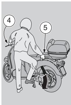
Do not get on the vehicle for starting it.
Do not start the engine with the vehicle positioned on the side stand.
To start the vehicle, position it on the centre stand.
Make sure that the dimmer switch (1) is in position “D”.
Set the engine stop switch (2) to position "O".
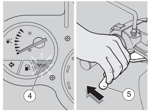
Turn the key (3) and set the ignition switch to position "O".
CAUTION
The engine oil pressure light (red) " 一 _ 一 ^ 一 4 on the instrument panel comes on and stays on until after the engine is running;
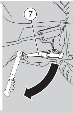
Lock at least one wheel, by pulling a brake lever (5). If this operation is not carried out, the start relay receives no current and therefore the engine does not start.
CAUTION After a long period of inactivity, carry out the operations described at page 29 (STARTING AFTER A LONG PERIOD OF INACTIVITY).
CAUTION To avoid the excessive wear of the battery, do not keep the starter pushbutton "③" pressed for more than five seconds (ten after a long period of inactivity). If the engine does not start within fifteen seconds, wait ten seconds before operating the starter button "③" again.
CAUTION
Avoid pressing the starter button "③"(6) when the engine is running, or the starter motor may damage.
Press the starter button "3" (6) without accelerating and release it as soon as the engine starts.
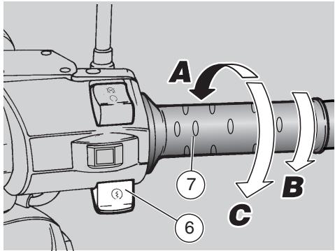
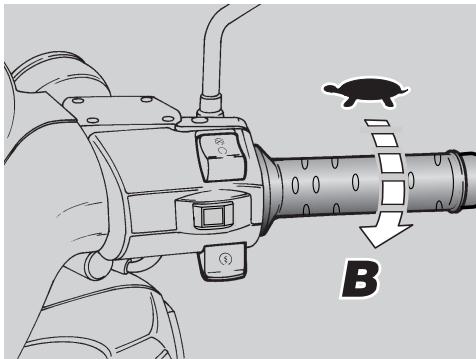
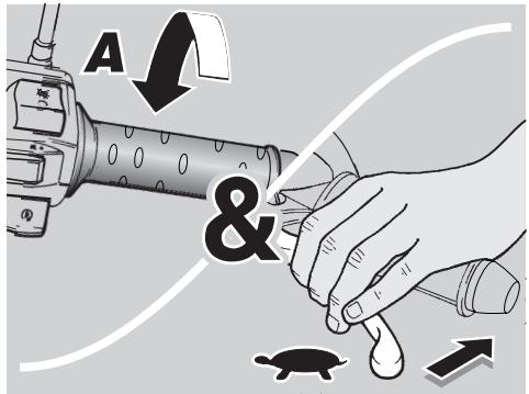
If the engine does not start in three or four seconds, slightly rotate the throttle grip (7) (Pos. B), keeping the starter push-button " (3) " (6) pressed.
CAUTION
As soon as the engine has started, the engine oil pressure warning light "..." (4) must go out. If the light stays on or comes on during normal operation, it means that oil pressure in the circuit is too low. Stop the engine immediately and contact an aprilia Authorised Dealer. Do not use the vehicle with insufficient engine oil, in order to avoid damaging the engine components.
Keep at least one brake operated and do not accelerate until you are ready to move off.
CAUTION
Never move off abruptly with a cold engine. To reduce emissions and fuel consumption, ride slowly until covering several miles to warm the engine up to operating temperature.
STARTING
WITH FLOODED ENGINE
If the starting is not carried out properly or if there is too much fuel in the intake ducts and in the carburettor, the engine may get flooded.
To clean a flooded engine:
Press the start push-button "③" (6) for a few seconds (letting the engine crank) with completely open throttle (7) (Pos.C).
STARTING THE ENGINE FROM COLD
If ambient temperature is low (close to or below 0^ ), you may have trouble starting the engine at the first attempt.
If so:
Hold down the starter button " ()^n (6) for at least five seconds and open the throttle grip (7) slightly (Pos. B).
If the engine starts:
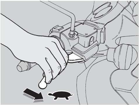
Release the throttle grip (7) (Pos.A).
If idle speed is erratic, flip the throttle grip (7) moderately several times.
If the engine fails to start
Wait a few seconds and repeat the COLD START PROCEDURE.
- If necessary, remove the spark plug, see page 44 (SPARK PLUG) and make sure that it is not wet.
If the spark plug is wet, clean and dry it.
Before reinstalling it:
CAUTION
Put a clean cloth on
the cylinder, near the spark plug seat, in order to protect it from oil sprays.
Press the start push-button " () (6) and let the starter run for about five seconds without accelerating.

STARTING AFTER A LONG PERIOD OF INACTIVITY
After a long period of inactivity, if the start is not immediate, this may be due to the fact that the fuel circuit is partially empty. If so:
Press the starter push-button "③" (6) for about ten seconds, in order to ensure the filling of the float chamber.
MOVING OFF AND RIDING
CAUTION Before moving off, carefully read section "Safe Riding", see page 5 (SAFE RIDING).
CAUTION
If the low fuel warning light "F" (8) positioned on the dashboard comes on while the vehicle is running, this means that the electric reserve is operating and there are still 2/ of fuel available. Refuel as soon as possible, see page 19 (FUEL).
WARNING
If you are riding solo, make sure the passenger footpegs are folded up before moving off.
While riding, keep your hands on the handlebar and your feet on the footpegs.
NEVER RIDE IN ANY POSITION OTHER THAN THE RECOMMENDED RIDING POSITION.
If you are riding with a passenger, give your passenger proper instructions to avoid problems when manoeuvring.
Before leaving, make sure that the stand/stands is/are completely up.
To move off:
Release the throttle grip (7) (Pos. A), engage the rear brake, then move the vehicle down the stand.
- Get on the vehicle, keeping at least one foot on the ground in order not to lose balance.
Adjust the rear-view mirrors.
WARNING
With the vehicle stopped, try to familiarise with the use of the mirrors. Convex mirrors provide a larger view, but any objects seen in these mirrors seem farther than they really are. It may take some time to learn to judge the distance of traffic behind accurately.
Release the brake lever and accelerate by rotating the throttle grip moderately (Pos. B); the vehicle will start moving.
CAUTION
Never move off abruptly with a cold engine.
To reduce emissions and fuel consumption, ride slowly until covering several miles to warm the engine up to operating temperature.
WARNING
Do not open and close the throttle repeatedly and continuously, or you may lose control of the vehicle.
When you need to brake, close the throttle and use both brakes for smooth braking; take care to apply the right amount of pressure to both brakes.
Using one brake only gives less braking power and you could lock a wheel and lose grip.
To stop uphill, decelerate completely and use the brakes to keep the vehicle at standstill.
Do not use engine braking or the clutch may overheat.
WARNING
When approaching a turn, slow down or brake and take the turn at moderate, constant speed or accelerate slightly; braking in a turn will greatly increase your chances of skidding.
Continued application of the brakes on long downhill grades may cause the brakes to overheat, thereby reducing braking efficiency. Shift down to use engine braking and apply both brakes intermittently.
Never ride downhill with the engine off! If the road surface is wet or slippery (snow, ice, mud, etc.), ride slowly, do not brake or swerve suddenly, or you may lose grip and fall.
Watch out for obstacles or sudden changes in the road surface.
Rough roads, rails, manhole covers, road markings, large steel plates near roadwork become slippery in the wet and should be avoided or negotiated with the greatest care, riding carefully and keeping the vehicle upright.
WARNING
Signal your intention to change lane or turn in good time using the turn indicators and avoid sudden swerving or movements.
Switch off the turn indicators as soon as you have finished turning.
Be extremely careful when overtaking or being overtaken.
When riding in the rain, the spray thrown up by the tyres of large vehicles will reduce your vision; the air wave created by a large vehicle may make you lose control of the vehicle.
RUNNING-IN
WARNING
After the first 1000km (625 mi), carry out the checking operations indicated in the column "After running-in" of the REGULAR SERVICE INTERVALS CHART, see page 34, in order to avoid hurting yourself or other people and/or damaging the vehicle.
Correct engine running-is essential to ensuring proper performance and durability.
Twisty, hilly roads are ideal for an effective running-in of engine, suspension and brakes.
CAUTION Only after the first 500 km (312 mi) of running-in it is possible to obtain the best speed and acceleration performance from the vehicle.
Follow these recommendations:
Do not open the throttle completely if the speed is low, both during and after the running-in.
0-100 km (0-62 mi)
Until you have covered the first 100 km (62 mi), use the brakes gently and avoid harsh, prolonged braking. This will help the brake pads bed in properly against the brake discs.
0-500 km (0-312 mi)
During the first 500km (312 mi), do not exceed the 80% of the maximum allowed speed.
- Avoid driving at constant speed for long distances.
After the first 1000 km (625 mi), progressively increase the speed until reaching the highest performance levels.
STOPPING
WARNING
If you can, do not stop or slow down suddenly and avoid limit-braking.
Release the throttle grip (pos. A) and gradually put on the brakes to stop the vehicle.
If you need to stop only briefly, keep at least one brake applied.
PARKING
WARNING
Park the vehicle on firm and level ground, to prevent it from falling.
Do not lean the vehicle against a wall, or lay it on the ground.
Make sure that the vehicle, and in particular hot vehicle components, may not put the safety of persons and children at risk.
Do not leave the vehicle unattended with the engine running or the key in the ignition switch.
Do not sit on the vehicle when the stand is down.
Stop the vehicle, see page 31 (STOPPING).
Set the engine stop switch (1) to position "X".
CAUTION
With the engine stopped and the ignition switch in position "O", the battery may run flat.
Rotate the key (2) and set the ignition switch (3) to position "X".
Position the vehicle on the stand, see on the side (PLACING THE VEHICLE ON THE STAND).
CAUTION It is not necessary to close the fuel tap when the engine is off, since it is equipped with an automatic closing system.
CAUTION
Never leave the key in the ignition switch.
Lock the steering, see page 15 (STEERING LOCK) and remove the key.
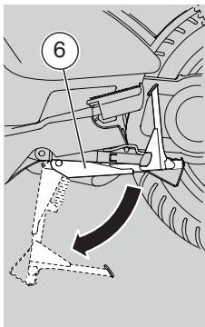
PLACING THE VEHICLE ON THE STAND
Carefully read page 31 (PARKING).
CENTRE STAND
Grasp the left grip (4) and the passenger grab rail (5).
Push down the stand lever (6).

SIDE STAND
Grasp the left grip (4) and the passenger grab rail (5).
WARNING
Risk of falling and overturning.
When the vehicle is straightened from the parking position to the driving position, the stand goes automatically up.
Push on the side stand with your right foot and lower it completely (7).
Lean the vehicle to the side until the stand is resting on the ground.
Turn the handlebar fully to the left.
WARNING
Make sure that the vehicle is stable.
SUGGESTIONS TO PREVENT THEFT
CAUTION
Do not use any "brake lock" devices. Failure to heed this warning can seriously damage the braking system and lead to an accident thus provoking serious injuries or death.
NEVER leave the key in the ignition switch and always use the steering lock.
Park the vehicle in a safe place, possibly in a garage or at a guarded parking place.
If possible, use the appropriate aprilia "Body-Guard" shielded cable OPT, or an additional antitheft device.
Make sure you have all the necessary documents with you and that the road tax has been paid.
Write your personal data and telephone number in this page to help trace the vehicle back to you in the event it is stolen and subsequently recovered.
SURNAME:
NAME:
ADDRESS:
TELEPHONE NO:
In most cases, stolen vehicles are identified through the data written on the Owner's Manual.
MAINTENANCE
WARNING
Risk of fire.
Keep fuel and other flammable substances away from electric components.
Before servicing or inspecting the motorcycle: stop the engine and remove the key from the ignition switch; allow for the engine and exhaust system to cool down; where possible, lift the motorcycle using adequate equipment placed on firm and level ground.
Ensure the area is well ventilated before proceeding.
Be careful of any parts of the engine or exhaust system which may still be hot to the touch in order to avoid scalds or burns.
Do not put any vehicle parts into your mouth: vehicle components are not edible and some of them are harmful or even toxic.
The vehicle is made up of not edible parts. Never bite, suck, chew or swallow any part of the vehicle for any reason.
CAUTION
Unless expressly indicated otherwise, reassembly is a reversal of the disassembly procedure.
Wear latex gloves during servicing.
Normally, the owner can take care of routine maintenance. However, some maintenance operations require specific tools and are best left to experienced mechanics.
If you need assistance or technical advice, contact your aprilia Authorised Dealer, for guaranteed accurate, prompt service.
We recommend having the vehicle road-tested at the aprilia Authorised dealer after repair or servicing.
In addition, perform the "Pre-ride checks" after each maintenance operation, see page 26 (PRE-RIDE CHECKS CHART).
SCHEDULED MAINTENANCE CHART
OPERATIONS TO BE CARRIED OUT BY THE aprilia Authorised dealer (CAN BE CARRIED OUT BY THE USER AS WELL).
| Component | After running-in [1000 km (625 mi)] | Every 6000 km (3750 mi) or 8 months | Every 12000 km (7500 mi) or 16 months |
| Rear shock absorbers | ① | ① | |
| Battery / Electrolyte level | ① | ① | |
| Spark plug | ① | ① | ③ |
| Carburettor - idling | ④ | | ① |
| Air filter | | ② | |
| Throttle operation | ① | ① | |
| Brake locking operation | ① | ① | |
| Converter grease | | ③ | |
| Stop light switch | | ① | |
| Coolant | ① | every 1000 km: ①/every 16 months: ③ |
| Engine oil | ③ | every 1000 km: ①/every 6000 km: ③ |
| Transmission fluid | ③ | every 6000 km: ①/every 24000 km: ③ |
| Headlight beam direction - operation | | ① | |
| Tyre - inflation pressure | every month:① |
| Battery terminals tightening | ① | | |
| Front suspension | ① | ① | |
| Brake pad wear | ① | every 2000 km① |
| ① = check and clean, adjust, lubricate or change, if necessary; ② = clean; ③ = change; ④ = adjust.Carry out the maintenance operations more frequently if you use the vehicle in rainy and dusty areas or on uneven ground. |
OPERATIONS TO BE CARRIED OUT BY THE aprilia Authorised dealer.
| Component | After running-in [1000 km (625 mi)] | Every 6000 km (3750 mi) or 8 months | Every 12000 km (7500 mi) or 16 months |
| Idle mixture (CO) | | ① | |
| Converter rollers and converter plastic guides | | ① | ③ |
| Converter belt | | ① | ③ |
| Steering tube bearings | ① | ① | |
| Engine oil filter | ③ | ③ | |
| Wheel bearings | | ① | |
| Secondary air scoop filter | | ② | |
| Converter cover air filter | | ② | |
| Clutch jaws | | | ① |
| Valve clearance | | ① | |
| Brake fluid | ① | ① | ①every 2 years:③ |
| Front suspension fluid | ① | ① | ③ |
| Engine oil filter screen and magnetic screw | ① | ① | |
| Converter rollers and converter plastic guides | | ① | ③ |
| Wheels / tyres | | ① | |
| Nut, bolt, screw tightening | ① | ① | |
| Cylinder head nut tightening | ① | | |
| Battery terminals tightening | ① | | |
| Draining brake fluid | ① | | |
| Fuel hose | | ① | every 2 years:③ |
| ① = check and clean, adjust, lubricate or change, if necessary; ② = clean; ③= change; ④ = adjust.Carry out the maintenance operations more frequently if you use the vehicle in rainy and dusty areas or on uneven ground. |
IDENTIFICATION DATA
It is a good rule to report the frame and engine numbers in the space provided in this manual.
The frame number must be quoted when purchasing spare parts.
CAUTION Altering a vehicle identification numbers is illegal and punished by the law with fines and imprisonment. In addition, altering the frame number invalidates the warranty.
FRAME NUMBER
The frame number is stamped on the frame central tube. To read it, it is necessary to remove the front inspection cover, see page 42 (REMOVING THE FRONT INSPECTION COVER).
Frame no.
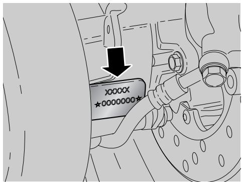
ENGINE NUMBER
The engine number is stamped near the lower support of the rear shock absorber.
Engine no.
CHECKING AND TOPPING UP ENGINE OIL LEVEL
Carefully read page 19 (LUBRICANTS), page 33 (MAINTENANCE) and page 59 (LUBRICANT CHART).
Check
CAUTION Position the vehicle on firm and flat ground.
Position the vehicle on the centre stand.
WARNING
The engine and the components of the exhaust system become very hot and remain hot for some time after the engine has been stopped. Before handling these components, wear insulating gloves or wait until the engine and the exhaust system have cooled down.
- Stop the engine and let it cool down, in order to allow the oil to flow into the oil pan and to cool down.
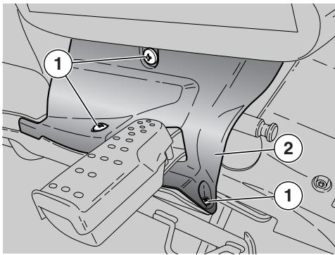
Slightly raise rider footpeg left pad.
Take down left passenger footrest.
Release the three screws (1) securing oil inspection cover (2).
Remove the oil inspection cover (2) from vehicle left-hand side.
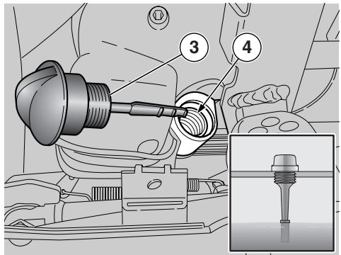
Unscrew and extract the plug/dipstick (1).
Clean the part in contact with the oil with a clean cloth.
- Tighten the plug/dipstick (3) completely, screwing it into the filling hole (4).
- Withdraw the plug/dipstick (3) again and read the oil level on the dipstick itself:
MAX= maximum level
MIN = minimum level.
The difference between "MAX" and "MIN" amounts to approximately 200 cu. cm.
- The level is correct if the oil reaches approx. the "MAX" mark on the dipstick.
CAUTION
Never exceed the "MAX" mark or let oil level drop below the "MIN" mark, as this may lead to severe engine damage.
If necessary, provide for topping up.
TOPPING UP
Pour a small quantity of oil in the filling hole (4) and wait about one minute, so that the oil flows into the oil pan.
- Check the oil level and top up if necessary.
- Top up by adding small quantities of oil, until reaching the prescribed level.
At the end of the operation, screw and tighten the plug/dipstick (3).
WARNING
Do not use the vehicle with insufficient lubrication or with contaminated or unsuitable lubricants, since this would cause early wear of the moving parts and may also cause irreparable failures.
AIR FILTER
Carefully read page 33 (MAINTENANCE).
The air filter should be inspected and cleaned every 6000km (3750 mi), depending on the conditions of use.
If the vehicle is used on dusty or wet roads, the cleaning operations should be carried out more frequently.
To clean the filtering element it is necessary to remove it from the vehicle.
REMOVING
Raise the seat, see page 17 (UNLOCKING/LOCKING THE SEAT).
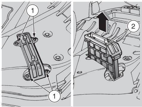
Release and remove the screws (1).
- Withdraw the complete air filter (2) from above.
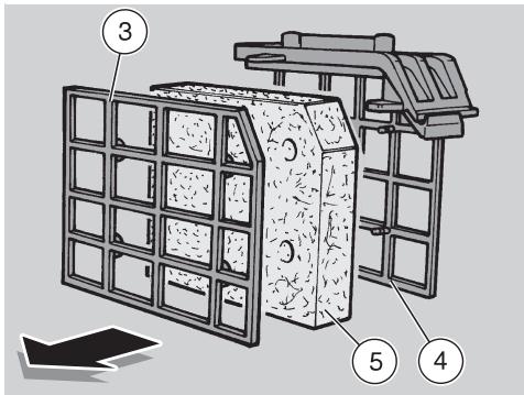
Separate the screen (3) from the support (4).
Remove the filtering element (5).
CLEANING
WARNING
Do not use petrol or inflammable solvents to wash the filtering element, in order to avoid fires or explosions.
Wash the filtering element (5) with clean, non-inflammable solvents or solvents with high volatility point, then let it dry thoroughly.
Apply a filter oil on the whole surface of the filtering element.
- Check if there are residues in the lower part of the drain hose (6).
CAUTION If there are residues coming from the air box, remove them by proceeding as follows:
Remove the plug (7).
Drain the contents into a container and deliver it to a waste collection centre.
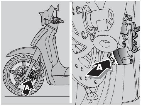
CHECKING THE BRAKE PADS FOR WEAR
Carefully read page 20 (BRAKE FLUID - recommendations), (DISC BRAKES) and page 33 (MAINTENANCE).
CAUTION The following instructions apply to both braking systems.
Check the brake pads for wear after the first 1000km (625 mi) and then every 2000 km (1250 mi). The rate at which brake pads will wear depends on vehicle usage, riding style and road surface condition.

WARNING
Inspect the brake pads before each ride.
Outlined below is a quick brake pad inspection procedure:
Position the vehicle on the centre stand.
Visually inspect the area between brake disc and brake pads.
Use a flashlight and a mirror, proceed as follows:
From below, on the front part, for the left pad (A);
from above, on the front part, for the right pad (B).
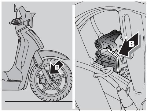
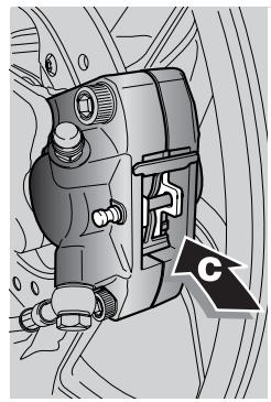
REAR BRAKE CALLIPER
- From above, on the rear part, for both pads (C).

WARNING
If brake pads were allowed to wear down until uncovering the metal substrate, metal-to-metal contact with the brake disc would lead to rattle and the brake calliper sparking; this would result in loss of braking and brake disc damage, causing a dangerous riding condition.
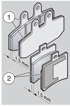
- Have the brake pads changed when the lining material of even just one pad is worn down to nearly 1.5 ~mm , or when any one of the wear indicators is no longer visible.
- Front brake pads (1);
- rear brake pads (2).

WARNING
Have the coolant changed at an aprilia Authorised Dealer.
INSPECTING THE FRONT AND REAR SUSPENSIONS
Carefully read page 33 (MAINTENANCE).
CAUTION
Have the front fork oil changed by an aprilia Authorised Dealer, for guaranteed accurate, prompt service.
Have the front suspension fluid and fork oil seals checked every 12000 km (7500 mi) or every 2 years.
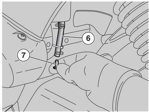
ADJUSTING THE REAR SUSPENSION
The rear suspension consists of a double effect shock absorber (compression/rebound damping) fixed to the engine by means of a silentblock.
The shock absorber is provided with a ring nut for the adjustment of the spring preload. The standard adjustment, set by the manufacturer, is suitable for a rider weighing about 70kg . If your weight and needs are different, adjust the ring nut (1) with the appropriate spanner provided in the tool kit, thus setting the ideal travelling conditions.
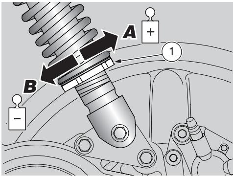
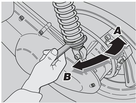
Slightly unscrew the locking ring nut (2) by means of the appropriate spanner.
CAUTION
The adjusting ring nut must not be screwed in for more than 14mm . If this limit is exceeded, even the slightest unevenness of the ground will make the vehicle jerk while running.
Turn the adjusting ring nut (1) (shock absorber spring preload adjustment) (see table).
ADJUSTMENT OF THE REAR SUSPENSION SPRING PRELOAD
| Adjusting ring nut | Rotation (arrow A) | Rotation (arrow B) |
| Function | Spring preload increase | Spring preload decrease |
| Track alignment | The vehicle is more rigid | The vehicle is less rigid |
| Recommended kind of road | Smooth or normal roads | Roads with uneven surface |
| Notes | Ride with passenger | Ride without passenger |
REMOVING THE CENTRAL INSPECTION COVER
Carefully read page 33 (MAINTENANCE).
Position the vehicle on the centre stand.
★Unscrew and remove the two screws (1).
CAUTION
Proceed with care. Do not damage the tabs and/or their seats. Handle plastic and paint-finished parts with care to avoid scratching or damage.
Remove the central inspection cover (2).
CAUTION
Upon reassembly, fit the tabs correctly in the appropriate seats.
REMOVING THE CENTRAL FAIRING
Carefully read page 33 (MAINTENANCE).
Remove the central inspection cover, see on the side (REMOVING THE CENTRAL INSPECTION COVER).
Raise the seat, see page 17 (UNLOCKING/LOCKING THE SEAT).
Release and remove the screws (3).
CAUTION
Proceed with care. Do not damage the tabs and/or their seats. Handle plastic and paint-finished parts with care to avoid scratching or damage.
Moderately open the rear part of the central fairing (4).
Remove the central fairing (4) by withdrawing it from the front.
CAUTION
Upon reassembly, fit the tabs correctly in the appropriate seats.
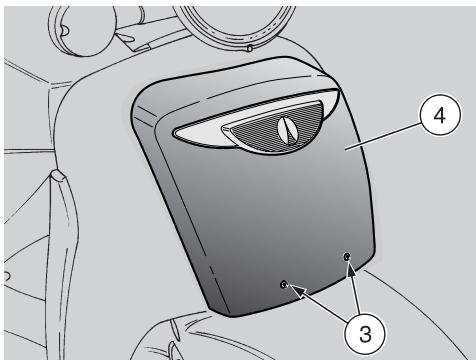
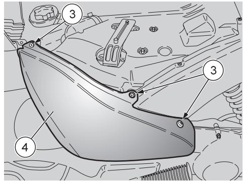
REMOVING THE FRONT COVER
Carefully read page 33 (MAINTENANCE).
Position the vehicle on the centre stand.
Release and remove the screws (3).
CAUTION
Proceed with care. Do not damage the tabs and/or their seats.
Handle plastic and paint-finished parts with care to avoid scratching or damage.
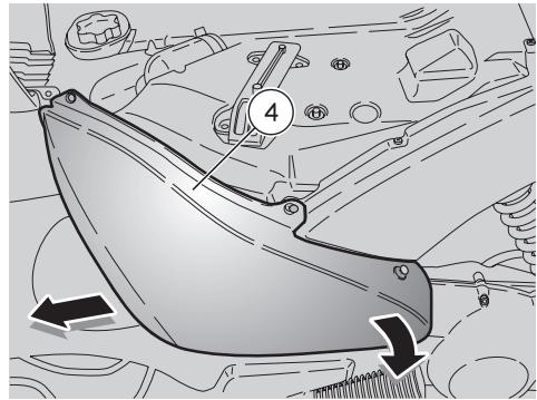
Remove the front cover (4) by pulling it downwards.
CAUTION
Upon reassembly, fit the tabs correctly in the appropriate seats.
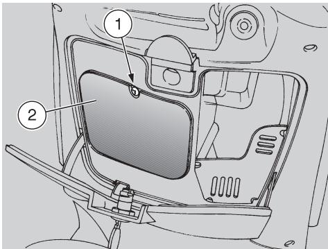
REMOVING THE FRONT INSPECTION COVER
Carefully read page 33 (MAINTENANCE).
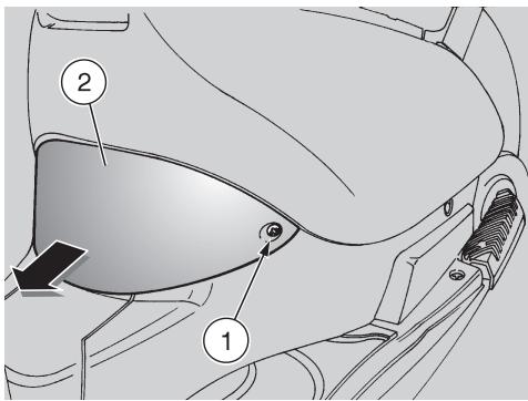
Open the glove compartment, see page 18 (GLOVE COMPARTMENT).
Unscrew and remove the screw (1).
Remove the front inspection cover (2).
CAUTION
Upon reassembly, fit the tabs correctly in the appropriate seats.
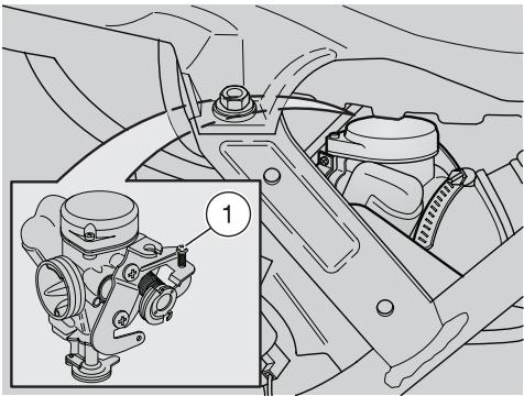
IDLING ADJUSTMENT
Carefully read page 33 (MAINTENANCE).
Adjust the idling speed every time it is erratic.
To carry out this operation, proceed as follows:
Ride for a few miles until reaching the normal operating temperature, see page 15 (Coolant temperature indicator "") then stop the engine.
Remove the central inspection cover, see page 41 (REMOVING THE CENTRAL INSPECTION COVER).
Remove the central fairing, see page 41 (REMOVING THE CENTRAL FAIRING)
Connect an electronic rev counter to the spark plug cable.
Start the engine.
The engine idle speed must be approximately 1600 ± 100 rpm. In this case the engine does not make the rear wheel rotate.
If necessary:
Working on the front left side of the vehicle, adjust the screw (1) positioned on the right side of the carburettor.
By SCREWING IT (clockwise), you increase the engine rpm.
By UNSCREWING IT (anticlockwise), you decrease the engine rpm.
Turn the throttle twistgrip, accelerating and decelerating a few times to make sure that it operates correctly and to check if the idling speed is constant.
CAUTION Do not turn the air adjusting screw to avoid variations of the carburetion setting.
If necessary, contact an aprilia Authorised Dealer.
ADJUSTING THE THROTTLE TWISTGRIP
Carefully read page 33 (MAINTENANCE).
There should be 2 - 3 mm free play in the throttle twistgrip (measured at twistgrip edge).
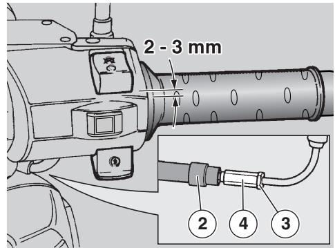
If this is not the case, proceed as follows:
Position the vehicle on the centre stand.
Withdraw the protection (2).
- Slacken the lock nut (3).
- Rotate the adjuster (4) until achieving the specified free play.
- When finished, tighten the lock nut (3) and check free play again.
Refit the protection (2).
WARNING
When finished, turn the handlebar to make sure its movement does not affect the engine idle rpm and check that the throttle grip - when opened and then released - returns smoothly to the closed position.
SPARK PLUG
Carefully read page 33 (MAINTENANCE).
Check the spark plug after the first 1000 km (625 mi) and change it every 6000 km (3750 mi). At regular intervals, remove the spark plug and clean off any carbon deposits or replace as required.
To reach the spark plug:
Remove the central inspection cover, see page 41 (REMOVING THE CENTRAL INSPECTION COVER).
To remove and clean the spark plug:
WARNING
Before carrying out the following operations, let the engine and the silencer cool down to ambient temperature, in order to avoid burns.
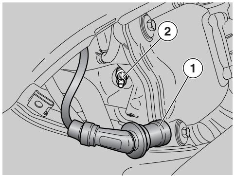
Pull the cap (1) off the spark plug (2).
Remove all the dirt from the base of the spark plug, then unscrew it with the spanner you will find in the tool kit and extract it from its seat, taking care that neither dust nor other substances enter the cylinder.
Make sure that there are neither carbon deposits, nor corrosion marks on the electrode and on the central part; if necessary, clean them with the special cleaners for spark plugs, with an iron wire and/or a metal brush.
- Energetically blow some air, in order to prevent the removed residues from getting into the engine.
Change the spark plug if it shows cracks on the insulating material, corroded electrodes or excessive deposits.
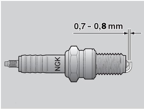
Check the electrode gap with a feeler gauge.
The gap must be 0.7 - 0.8 ~mm ; if necessary, adjust it, carefully bending the earth electrode.
- Make sure that the washer is in good condition. Fit the washer and screw the spark plug finger-tight to avoid damaging the thread.
Tighten using the spanner supplied with the tool kit. Screw in each spark plug by one half turn to compress the washer.
Spark plug tightening torque: 18 Nm (1.8 kgm).
CAUTION
The spark plug must be tightened firmly, otherwise the engine may overheat and severe damage may occur.
Use recommended spark plugs only, see page 56 (TECHNICAL DATA). A spark plug of the wrong rating may shorten engine life and cause loss of performance.
Position the spark plug cap properly, to prevent it coming off due to engine vibration.
Refit the central inspection cover, see page 41 (REMOVING THE CENTRAL INSPECTION COVER).
BATTERY
Carefully read page 33 (MAINTENANCE).
Check battery fluid level and terminal tightening after the first 1000 km (625 miles) and every 6000 km (3750 miles) afterwards.
WARNING
Risk of fire.
Keep fuel and other flammable substances away from electric components.
Battery fluid is toxic, caustic and corrosive; it contains sulphuric acid and contact with skin will cause severe burns. Wear protective clothing and a face or eye protection before servicing the battery.
In case of contact with skin, rinse with plenty of fresh water.
In case of contact with eyes, rinse with plenty of water for fifteen minutes and immediately contact an eye specialist without delay.
If battery fluid is accidentally swallowed, drink abundant water or milk, then continue with magnesia milk or vegetable oil and seek medical advice immediately.
The battery gives off explosive gases and must be kept away from flames and sources of ignition or heat; do not smoke near the battery.
Charge or use the battery in a well-ventilated place. Do not inhale the gasses produced by the battery under charging.
KEEP AWAY FROM CHILDREN.
Avoid leaning the vehicle at steep angles or you might spill battery fluid.
CAUTION
Never invert the battery cables.
Ensure that the ignition switch is in position "×" before connecting or disconnecting the battery, otherwise some components might damage.
Connect the positive cable (+) first and then the negative cable (-) .
Disconnect in the reverse order.
Battery fluid is corrosive.
Do not spill it, especially on plastic parts.
If you have installed a "MAINTENANCE-FREE" battery, use a specific battery charger to recharge it (this will be the constant voltage/amperage or constant voltage type).
Using a conventional battery charger might damage your maintenance-free battery.
LONG INACTIVITY OF THE BATTERY
If the vehicle remains unused for more than fifteen days, it is necessary to recharge the battery, in order to prevent sulphation, see page 47 (CHARGING THE BATTERY).
Remove the battery, see page 46 (REMOVING THE BATTERY) and store it in a cool, dry place.
To avoid degradation in the wintertime or while the vehicle is stored away, check battery charge at regular intervals (monthly).
- Recharge the battery fully at a normal charge rate, see page 47 (CHARGING THE BATTERY).
If you are leaving the battery installed to the vehicle, disconnect the cables from the terminals.
Carefully read page 45 (BATTERY).
Make sure that the ignition switch is in position "X".
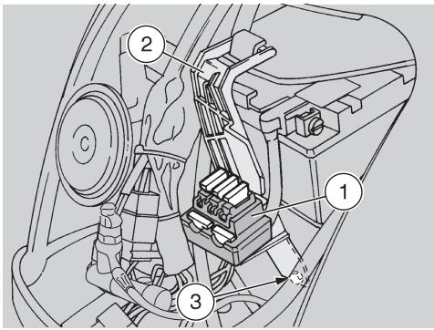
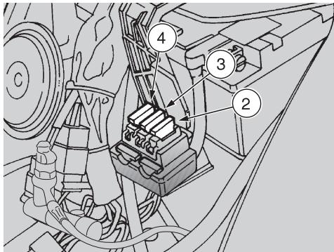
Remove the front cover, see page 42 (REMOVING THE FRONT COVER).
Remove the fuse block (1) from the clip (2).
Release and remove the screw (3).
Remove the clip (2).
- Withdraw the battery case (4) together with the battery.
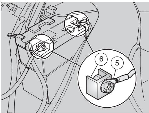
CHECKING AND CLEANING THE TERMINALS
Remove the battery case, see on the side (EXTRACTING THE BATTERY CASE).
- Check that battery lead connections (5) and battery terminals (6) are:
- in good condition (and not corroded or covered with deposits);
covered with neutral grease or Vaseline.
If necessary:
Disconnect first the negative (-) and then the positive cable (+).
Brush with a wire brush to eliminate any sign of corrosion.
Connect first the positive (+) and then the negative cable (-) .
Coat the terminals of cables and battery with neutral grease or Vaseline.
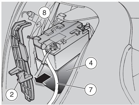
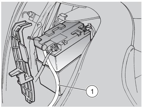
REMOVING THE BATTERY
Remove the battery case, see on the side (EXTRACTING THE BATTERY CASE).
Disconnect first the negative (-) and then the positive cable (+).
Remove the battery breather pipe (7).
Remove the battery (8), and put it on a flat surface in a cool, dry place.
WARNING
Once removed, the battery must be stored in a safe place and kept away from children.
- Refit the battery case, see on the side (EXTRACTING THE BATTERY CASE).
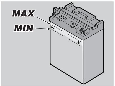
CHECKING BATTERY FLUID LEVEL
To check the battery fluid level:
Remove the battery case, see page 46 (EXTRACTING THE BATTERY CASE).
- Make sure that battery fluid level is between the "MIN" and "MAX" marks on the battery. If not so:
CAUTION
Top up with distilled water only. Do not exceed the "MAX" mark, because battery fluid expands when the battery is under charging.
Add distilled water until achieving correct level.
CHARGING THE BATTERY
Remove the battery, see page 46 (REMOVING THE BATTERY).
Remove the battery caps.
- Check electrolyte level, see on the side (CHECKING BATTERY FLUID LEVEL).
Connect the battery to a battery charger.
Recommended charge rate is 1/10th of battery capacity.
After charging the battery, check battery fluid level again and top up with distilled water if needed.
Refit the caps.
CAUTION
When you disconnect the battery charger, allow 5-10 minutes before refitting the battery, as it will keep producing gas for a few minutes.
INSTALLING THE BATTERY
Remove the battery case, see page 46 (EXTRACTING THE BATTERY CASE).
Refit the battery into its mount.
Refit the battery breather pipe (1).
CAUTION
Always connect the battery breather pipe, to prevent the sulphuric acid vapours from corroding the electric system, painted parts, rubber elements or gaskets when they exit the breather pipe itself.
Connect first the positive (+) and then the negative cable (-) .
Coat the terminals of cables and battery with neutral grease or Vaseline.
Refit the battery case, see page 46 (EXTRACTING THE BATTERY CASE).
CHANGING THE FUSES
Carefully read page 33 (MAINTENANCE).
CAUTION
Do not repair faulty fuses. Never use a fuse of a rating other than specified. This could damage the electric system or cause a short circuit, with the risk of fire.
CAUTION When a fuse fitted in a particular position keeps blowing frequently, there might be a short circuit or overloading. In this case, contact an aprilia Authorised Dealer.
Checking the fuses is recommended whenever an electric component fails to operate or is malfunctioning, or when the engine does not start. Check the 7.5 A and the 15 A fuses first and then the 20A fuse.
Check as follows:
Remove the front cover, see page 42 (REMOVING THE FRONT COVER).
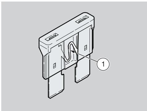
- Extract all fuses one by one and check for blown fuses. A blown fuse is identified by the filament (1) in the centre being broken.
- Before replacing a fuse, identify the cause of the failure, if possible.
Replace the blown fuse with a new one with equal current rating.
CAUTION When you use one of the spare fuses, remember to add a new spare fuse into the proper seat.
Refit the front cover, see page 42 (REMOVING THE FRONT COVER).
ARRANGEMENT OF THE FUSES
From the ignition switch to ignition.
From the ignition switch to all light loads and horn.
From the battery to ignition switch, voltage regulator, electric fan.

CHECKING THE SWITCHES
The vehicle is fitted with two switches:
- Stoplight switch on the rear brake control lever.
- Stoplight switch on the front brake control lever.
If you need assistance or technical advice, contact your aprilia Authorised Dealer, for guaranteed accurate, prompt service.

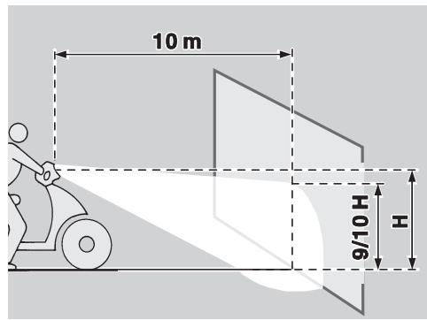
VERTICAL ADJUSTMENT OF THE HEADLIGHT BEAM
For a quick beam inspection, place the vehicle on level ground, ten metres away from a vertical wall.
Switch on the low beam, sit astride the vehicle and make sure that the light spot on the wall is just below the horizontal line of the headlight (about nine/tenth of overall height).
To adjust the headlight beam:
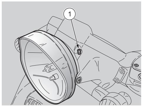
Remove the headlight fairing.
Turn the appropriate screw (1) with a screwdriver.
TIGHTEN (clockwise) to raise the beam;
SLACKEN (anticlockwise) to lower the beam.
BULBS
Carefully read page 33
(MAINTENANCE).
WARNING
Risk of fire.
Keep fuel and other flammable substances away from electric components.
CAUTION
Before changing a bulb, set the ignition switch to position "×" and allow a few minutes for the bulb to cool down.
Wear clean gloves or use a clean, dry cloth to handle the new bulb.
Do not put your fingerprints on the bulb, as this may lead to overheating and failure.
If you have handled the bulb with bare hands, clean it with alcohol to avoid any damage.
DO NOT PULL ON THE WIRES.
CAUTION Before changing a bulb, check the fuses, see page 48 (CHANGING THE FUSES).
CHANGING THE TURN INDICATOR BULBS
Carefully read on the side (BULBS).
To change the bulbs:
CAUTION The following information applies to all turn indicators.
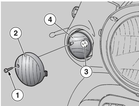
Unscrew and remove the screw (1).
CAUTION
Proceed with care.
Do not damage the tabs and/or their seats.
Remove the lens (2).
Press the bulb (3) slightly and rotate it anticlockwise.
CAUTION If the bulb holder (4) comes off, refit it into its seat so that the slotted opening of the holder matches the hole for the screw.
Extract the bulb from its seat.
CAUTION Insert the bulb into the bulb holder, so that the two pins slide into the slots in the holder.
Fit a new bulb of equal rating.
Upon reassembly:
CAUTION Make sure that the lens (2) locates correctly into its seat on refitting.
CAUTION
Tighten the screw (1) gradually. Do not overtighten or the shield (2) will damage.
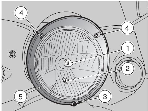
CHANGING THE HEADLIGHT BULBS
Carefully read page 50 (BULBS).
The headlight accommodates:
- One low/high beam bulb (1).
- One parking light bulb (2).
To change the bulbs:
Release and remove the screw (3).
CAUTION Upon reassembly, take care not to reverse the position of the screws (3) and (4).
Release and remove the screws (4).
Remove the frame (5).
Remove the reflector (6).
CAUTION Upon reassembly,
install the reflector (6) correctly, matching the insertion seats.

LOW/HIGH BEAM BULB (HALOGEN BULB)
CAUTION
Never pull on the wiring to disconnect a bulb connector.
Grasp the bulb connector (7) and pull to disconnect it from the bulb (1).
Position the bulb holder (8) in the reflector and rotate it clockwise.
Remove the bulb (1).
Upon reassembly:
CAUTION Insert the bulb (1) in the holder, making the two bulb pins (9) match with the relevant guides (10) on the reflector seat.
Position the bulb holder (8) in the reflector and rotate it clockwise.
Connect the bulb electric connector (7).
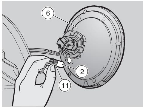
PARKING LIGHT BULB
CAUTION
Do not pull on the wires to remove the bulb holder.
- Grasp the bulb holder (11) and pull to extract.
Remove the parking light bulb (2) and fit a new bulb of equal rating.
CHANGING THE TAIL LIGHT BULBS
Carefully read page 50 (BULBS).
The tail light accommodates:
- A parking light/stoplight bulb (1).
- One number plate bulb (2).
To change the bulbs:
Loosen the screws (3).
Remove the lens (4).
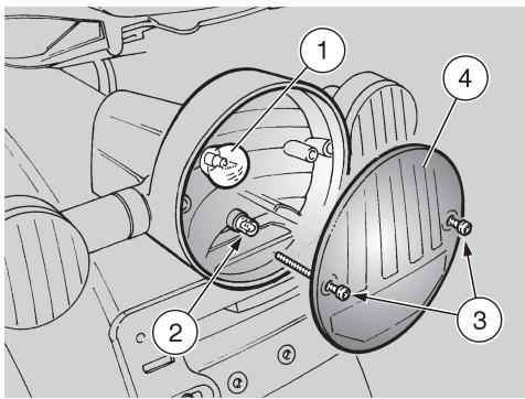
PARKING LIGHT/STOPLIGHT BULB
Push down the bulb (1) gently and twist anticlockwise.
Extract the bulb from its seat.
CAUTION Insert the bulb into the bulb holder, so that the two pins slide into the slots in the holder.
Fit a new bulb of equal rating.

NUMBER PLATE BULB
Remove the bulb (2) and fit a new bulb of equal rating.
CAUTION Make sure that the lens locates correctly into its seat on refitting.
CAUTION
Tighten the screw (3) moderately and carefully, to avoid damaging the lens.
WARNING
Before transporting the vehicle, it is necessary to empty the fuel tank and the carburettor completely, see below (DRAINING THE FUEL TANK), making sure that both are completely dry.
During transport, the vehicle must be firmly secured in an upright position to avoid fuel, oil and coolant leaks.
If stranded, do not have the vehicle towed - contact a roadside service firm instead.
DRAINING THE FUEL TANK
Carefully read page 19 (FUEL).
WARNING
Risk of fire.
Allow some time for the engine and muffler to cool down completely.
Fuel vapours are noxious to human health.
Ensure the area is well ventilated before proceeding.
Do not inhale fuel vapours.
Do not smoke or use open flames.
DO NOT RELEASE FUEL INTO THE ENVIRONMENT.
Position the vehicle on the centre stand.
- Stop the engine and wait until it has cooled down.
Prepare a container large enough to hold the fuel in the tank and place it on the floor on the left side of the vehicle.
Remove the fuel filler plug.
Drain fuel using a manual pump or similar system.
WARNING
After draining the tank, tighten the filler plug.
To drain the carburettor completely, proceed as follows:
Remove the central inspection cover, see page 41 (REMOVING THE CENTRAL INSPECTION COVER).
Remove the central fairing, see page 41 (REMOVING THE CENTRAL FAIRING)
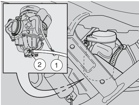
- Put the free end of the hose (1) into a receptacle.
Working on the front left side of the vehicle, open the carburettor outlet by loosening the drain screw (2) positioned under the float chamber.
When all the fuel has flowed out of the carburettor:
Tighten the drain screw (2) completely.
CAUTION
Tighten the drain screw (2) with care, to avoid fuel leakages from the carburettor during refuelling.
If necessary, contact an aprilia Authorised Dealer.

Clean the vehicle frequently if it is used in particular areas or conditions, such as:
Pollution (urban and industrial areas)
High salinity and humidity (sea areas, hot and damp climates).
Seasonal/environmental conditions (road salt and chemicals spread on the roads in the wintertime).
Make sure to clean off any industrial residue and pollutants, tar, dead insects, bird droppings, etc. from the body panels and fairings.
- Avoid parking the vehicle under trees. Resins, fruits or leaves falling from the trees may contain aggressive chemical substances that may damage the paintwork.
WARNING
After the vehicle has been washed, braking efficiency could be temporarily impaired because the friction surfaces of the braking systems may still be wet. Ride carefully as braking distance will be longer. Operate the brakes repeatedly to restore normal operation.
Perform the recommended pre-ride checks, see page 26 (PRE-RIDE CHECKS CHART)
To remove dirt and mud from painted surfaces, use a low-pressure water jet on dirty areas, remove mud and dirt with a soft car body sponge soaked with abundant water and shampoo (2 - 4% parts of shampoo).
Then rinse with plenty of water and dry with chamois leather.
Clean the outer parts of the engine using a degreaser, small brushes and cloth.
CAUTION
To clean the lights, use a sponge soaked with water and a neutral detergent, rubbing the surfaces delicately and rinsing frequently with plenty of water.
Wash the vehicle thoroughly before applying silicone wax.
Do not polish matt-painted surfaces with polishing paste.
Do not wash the vehicle under the sun, especially in the summertime, when the body is still warm, as the shampoo will dry before you can rinse it away and could damage the paint.
Do not use liquids at a temperature higher than 40^ to clean the plastic components of the vehicle.
Do not aim high-pressure water/air jets or steam jets at the following parts: wheel hubs, controls on the right and left side of the handlebar, bearings, brake master cylinders, instruments and indicators, silencer, glove/tool kit compartment, ignition switch/steering lock, cooler or radiator fins, fuel filler plug, lights and electric connections.
Do not clean any rubber and plastic parts and the seat with alcohol, petrol or solvents: use water and mild soap only.
WARNING
Do not apply protection waxes to the seat, or it may become slippery.
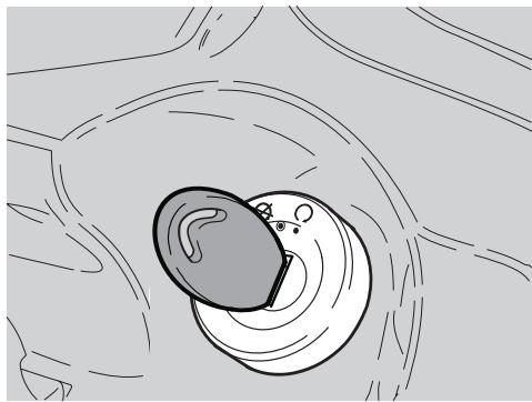
LONG PERIODS OF INACTIVITY
When the vehicle is to remain unused for long periods, some precautions are necessary to avoid damage.
Do not postpone necessary repairs or you could forget them when you take the vehicle out of storage; a general check up is also recommended.
Proceed as follows:
Empty the fuel tank and the carburettor, see page 53 (DRAINING THE FUEL TANK).
Remove the spark plug, see page 44 (SPARK PLUG).
Pour a teaspoon of engine oil (5-10 cu.cm) into the cylinder.
CAUTION
Put a clean cloth on
the cylinder, near the spark plug seat, in order to protect it from oil sprays.
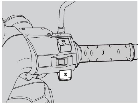
Turn the ignition switch to position "O" and press the engine start push-button "③" for a few seconds, to distribute the oil evenly on the cylinder surfaces.
Remove the cloth.
Refit the spark plug.
Remove the battery, see page 46 (REMOVING THE BATTERY) and page 45 (LONG INACTIVITY OF THE BATTERY).
Wash and dry the vehicle, see page 54 (CLEANING).
Polish painted surfaces with wax.
Inflate the tyres, see page 56 (TECHNICAL DATA).
- By means of a suitable support, position the vehicle so that both tyres are raised from the ground.
- Store the vehicle in an unheated, dry place, away from sunlight, where temperature is reasonably steady.

Wrap and tie a plastic bag around the exhaust pipe opening to keep moisture out.
Cover the vehicle avoiding plastic or waterproof covers.
AFTER STORAGE
Remove the cover and clean the vehicle, see page 54 (CLEANING).
- Check battery charge, see page 47 (CHARGING THE BATTERY) and fit it, see page 47 (INSTALLING THE BATTERY).
Fill the fuel tank, see page 19 (FUEL).
Perform the recommended pre-ride checks, see page 26 (PRE-RIDE CHECKS CHART).
WARNING
Test ride the vehicle at moderate speed in an area away from traffic.
| TECHNICAL DATA |
| DIMENSIONS | Max. Length | 2080 mm |
| Max. Width | 720 mm |
| Max. height (headlight fairing included) | 1330 mm |
| Seat height | 800 mm |
| Wheelbase 125 | 1400 mm |
| Wheelbase 250 | 1415 mm |
| Minimum ground clearance | 165 mm |
| Weight in running order 125 | 153 kg |
| Weight in running order 250 | 165 kg |
| ENGINE | Model 125 | M281M |
| Model 250 | M285M |
| Type | One-cylinder, 4-stroke engine with 4 valves, forced lubrication with wet sump, one overhead camshaft. |
| Number of cylinders | 1 |
| Total displacement 125 | 124 cu cm |
| Total displacement 250 | 244 cu cm |
| Bore / stroke 125 | 57 mm / 48.6 mm |
| Bore / stroke 250 | 72 mm / 60 mm |
| Compression ratio 125 | 12 ± 0.5 : 1 |
| Compression ratio 250 | 11.0 ± 0.5 : 1 |
| STARTING | electric |
| Engine idling rpm | 1600 ± 100 rpm |
| Clutch | automatic, dry centrifugal clutch |
| Gearbox | automatic |
| Cooling | liquid cooling, forced circulation with centrifugal pump |
| Valve clearance | Intake 0.10 Exhaust 0.15 |
| CAPACITIES | Fuel (reserve included) | 8.9 l |
| Fuel reserve | 2 l |
| Engine oil | |
| - engine oil and engine oil filter change | 1100 cu cm |
| Transmission fluid | 250 cu cm |
| Coolant | 1.2 l (50% water + 50% antifreeze with ethylene glycol) |
| Seats | 2 |
| Max. carrying load | |
| (rider + passenger + luggage) 125 | 180 kg |
| Max. carrying load | |
| (rider + passenger + luggage) 250 | 210 kg |
| TRANSMISSION | Converter | automatic, stepless |
| Primary | V-belt |
| Final | gears |
| Total engine/wheel ratio 125 | |
| - minimum | 36.5 |
| - maximum | 10.95 |
| Total engine/wheel ratio 250 | |
| - minimum | 22.36 |
| - maximum | 7.88 |
| CARBURETTOR | Model 125 250 | CVK7 30 Keihin |
| Model 125 250 | WVF7 Ø29 WALBRO |
| FUEL SUPPLY | Type | vacuum pump |
| Fuel | premium grade leaded petrol (4 Stars UK) or unleaded petrol with 95 RON and 85 MON octane rating minimum. |
| FRAME | Type | one beam at the front, split in two overlapping cradles at the rear, in steel tubes with high yield point |
| Steering head angle | 28° |
| Trail | 90 mm |
| SUSPENSIONS | Front | hydraulically operated telescopic fork |
| Stroke | 110 mm |
| Rear | hydraulic, double-effect shock absorber with preload adjustment |
| Stroke | 105 mm |
| BRAKES | Front | disc brake - Ø 260 mm - with hydraulic transmission |
| Rear | disc brake - Ø 240 mm - with hydraulic transmission |
| WHEEL RIMS | Type | in light alloy |
| Front | 2.50 x 16" |
| Rear | 3.00 x 16" |
| TYRES | Type | tubeless |
| Front | 110/80-16"55 P |
| Rear | 130/80-16"64 P |
| STANDARD INFLATION PRESSURE | |
| Front | 190 kPa (1.9 bar) |
| Rear | 190 kPa (1.9 bar) |
| INFLATION PRESSURE WITH PASSENGER | |
| Front | 200 kPa (2.0 bar) |
| Rear | 220 kPa (2.2 bar) |
| IGNITION | Type | Capacity discharge ignition with variable advance |
| Spark advance⑫ | Variable,managed by ECU. 5° minimum - 24°>4000 rpm |
| Spark advance⑬ | Variable,managed by ECU. 4° minimum - 15°>4000/6000 rpm |
| SPARK PLUG | Standard | NGK CR8EB |
| As an alternative | NGK CR7EB-NGK CR9EB |
| Spark plug gap | CHAMPION RG6YC-CHAMPION RG4HC |
| 0.7-0.8 mm |
| ELECTRIC | Battery | 12 V-12 Ah |
| SYSTEM | Fuses | 20-15-7.5 A |
| Generator (with permanent magnet)⑭ | 12 V-180 W |
| Generator (with permanent magnet)⑮ | 12 V-235 W |
| BULBS | Low/high beam | 12 V-55/60 W |
| Parking light | 12 V-3 W |
| Turn indicator light | 12 V-10 W |
| Rear parking light/stoplight | 12 V-5/21 W |
| Number plate light | 12 V-5 W |
| Instrument panel lighting | 12 V-1.2 W |
| WARNING LIGHTS | Turn indicators | 12 V-2 W |
| Engine oil pressure | 12 V-2 W |
| Low beam | 12 V-2 W |
| High beam | 12 V-2 W |
| Fuel reserve | 12 V-2 W |
LUBRICANT CHART
(Recommended) Engine oil: Agip 4T FORMULA RACING, SAE 5W - 40.
As an alternative to recommended oils, top brand oils meeting or exceeding CCMC G-4 A.P.I. SG specifications can be used.
(Recommended) Transmission fluid: Agip GEAR SYNTH, SAE 75W - 90.
As an alternative to recommended fluids, top brand oils meeting or exceeding CCMC GA.P.I. GL4 specifications can be used.
(Recommended) Fork fluid: Agip FORK 5W or Agip FORK 20W.
When you wish to obtain an intermediate response between those offered by Agip FORK 5W and Agip FORK 20W, you may mix the different products as follows:
SAE 10W = Agip FORK 5W 67% of volume + Agip FORK 20W 33% of volume.
SAE 15W = Agip FORK 5W 33% of volume + Agip FORK 20W 67% of volume.
Bearings and other lubrication points (recommended): Agip GREASE SM2.
As an alternative to recommended grease, use top brand rolling bearing grease that will resist a temperature range of -30^ + 140^ , with dropping point 150^ - 230^ , high corrosion protection, good resistance to water and oxidisation.
Battery lead protection: Neutral grease or Vaseline.
Spray grease for chains (recommended): Agip CHAIN LUBE.
WARNING
Use new brake fluid only. Do not mix different makes or types of oil without having checked bases compatibility.
Brake fluid: The system is filled with Autofluid FR. DOT Aglip BRAKE 5.1 DOT 4 (DOT 5 compatible).
As an alternative to the recommended product, top brand brake fluid meeting or exceeding SAE J1703, NHTSA 116 DOT 4, ISO 4925 specifications for synthetic brake fluid can be used.
WARNING
Use only nitrite-free antifreeze and corrosion inhibitors with a freezing point of -35^ as a minimum.
Engine coolant (recommended): Agip COOL.
As an alternative to the recommended product, top brand brake fluid meeting or exceeding CUNA NC 956-16 specifications for ethylene glycol coolant can be used.
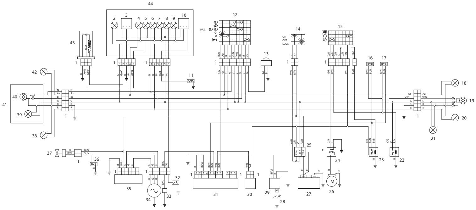
KEY TO WIRING DIAGRAM - Scarabeo 125
1) Multiple connectors
2) Instrument panel lamps
3) Fuel gauge
4) Left direction indicator warning light
5) Low fuel light
6) Low beam warning light
7) High beam warning light
8) Oil pressure light
9) Right direction indicator warning light
10) Water temperature gauge
11) Water temperature thermistor
12) Left dimmer switch
13) Warning horn
14) Key-operated switch
15) Right dimmer switch
16) Front brake light switch
17) Rear brake light switch
18) Left right turn indicator
19) Rear stop switch
20) Rear right turn indicator
21) Number plate light
22) Stoplight relay/ignition enable
23) Ignition relay
24) Starter relay
25) Fuses
26) Starter motor
27) Battery
28) Spark plug
29) H.T. coil
30) Automatic cold start
31) C.D.I. control unit
32) Oil pressure sensor
33)Pick-up
34) Generator
35) Voltage regulator
Thanks to ongoing technical updates and product-specific technical training, aprilia Authorised Network engineers are familiar with every detail of this vehicle and have the special equipment required for correct maintenance and repair.
A vehicle kept in sleek running order is a reliable vehicle. Pre-ride checks, proper maintenance at the recommended intervals and using aprilia Original Parts only are key factors!
To find contact information of the Authorised Dealer and/or Service Centre nearest you, please consult the Yellow Pages or the map provided at our web site:
When you demand aprilia Original Parts, you are purchasing products that have been developed and tested as early as the vehicle design stage. aprilia Original Parts systematically undergo strict quality control procedures to ensure total reliability and long service life.
Piaggio & C. S.p.A. wishes to thank its customers for the purchase of this vehicle:
- Do not release oil, fuel, polluting substances and components into the environment.
- Do not keep the engine running if it is not necessary.
- Avoid disturbing noise.
- Respect the environment.

aprilia part# 8104851
use+maintenancebook
第一版:2004年2月
再版:2006年9月-A
発行と印刷:
VALLEY FORGE DECA
Ravenna, Modena, Torino
DECA s.r.l.
登錄事務所おはこ管理部
Via Vincenzo Giardini, 11
48022 Lugo (RA) - Italia -
Tel.+39-0545-216611
Fax +39-0545-216610
www.vftis.com
deca@vftis.spx.com
监修:
Piaggio & C. S.p.A.
via G. Galilei, 1 - 30033 Noale (VE) - Italia
Tel. +39 - 041 58 29 111
Fax +39-041 44 10 54
www.aprilia.com
安全の開設の知らせ
Motorcycle Recycling
腐棄二輪車取圾店
厚生省生衡第521号
宏城废棄物处理指定業指定店
平成3年7月1日
(社)全国轻自動車協會連合會
廢業二輪車取扳店の証
1
K O P E N A 20
Yypó ψuξης 22
EAASTIKA 24
E3ATMIH/ΣIΛANSE 25
KANONEXPHH26
PPOKATAPKTIKOI EAEFXOI 26
EKKINHsH 27
EKKINHSH KAI OΔHΓHSH 29
ETPOEIMO 31
TAMATHMA 31
ΣTAOMEYΣH 31
TOI0OETHsH TOY I K Y K A O Y 2TO
32
PYOMIISH\PiΩ ANAPTHEHS 40
TnpnoTE TIG TnapakTu Odbnyies:
Mny TEPIOTpeTE ETVLwS Tn MaVetya KZIOU OTIG XaunAe OTOPOEc, T0Oo KA tAn DlApKEIA 000 KAI METAO TO OTPWIO.
0-100 km (0-62 mi)
EeYxETTpiTuTICaaAaeiesTwv7,5A kai 15A kai tAcaaAaeies20A.
Tia tov eAeYxO:
AqaipeoTe To eptpoc KaTó, . 42 (AΦAIPEsH IPOsOIOY KAnO)
Byalte mia ia tis aopaleieCs kai elevsTe av to oupuataki (1) evai koumuévo.
Piv avikataohtoe Tny aovaleia, avaŋtne Tny aiia TPOkαe OE Tn
Avtikataotne TIV kaevn aovaleia 1ia aaH Ta iDia aPTep.
EHMANTIKO Av xonaioiointheta iia aTIO Tc EeEobipkEs aospaaleis, TpoBleye va toTOeTeNoTemuia 0tN tcn.
ETTAVATOTIOEHTOTo EUMTPOoIO KAIO, 3A. oEλ. 42 (AΦAIPEeH IPOsOIOY KANO).
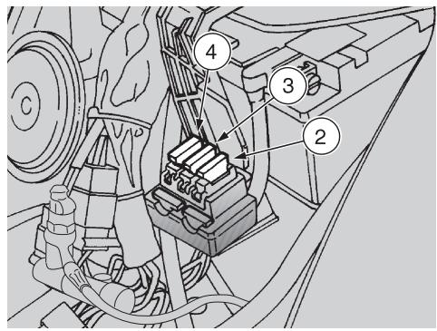
AIATAEH A2AANEION
-Aσφαλεια7,5A(2)
Ato to biakottnn Ekkivnoons Ews tnv avapaleqn.
-AoΦaλεια15A(3)
Anto oiaokottn Ekkivnons 0e 0la ta qopria wtwv kai koprvas.
-AoΦaλεια20A(4)
AnoTn matapia oTo diaKoTTn EkkivnoNS, to puOHTn taONs, Tov nEeKtpiKO aveiOTnpa.

EAERXOZAIKONTQN
Στο δικυκλο Αντάρχουν Ḁύο διακόπες:
- i k n o a t a Tou p v o u i
- i k 0T0T 0Tn maVet a Tou opevou
Av evai aTapaitnTo eva oepic n iA TeXviK ouBouAl, anEuvtheta eEvav Etioanoc AvTIPOoosAprilia, Tou Eyyuatai eva EIIeIeNevo kAI Pooeyevo oepic.