
QUASAR 180 - Scooter APRILIA - Free user manual and instructions
Find the device manual for free QUASAR 180 APRILIA in PDF.
| Product type | Scooter |
| Brand | APRILIA |
| Model | QUASAR 180 |
| Dimensions (L x W x H) | 1790 x 970 x 1060 mm (Grip) / 1675 x 970 x 1060 mm (Hp) |
| Curb weight | 174 kg (Grip) / 171 kg (Hp) |
| Engine | 4-stroke, horizontal single-cylinder, 169 cc |
| Bore x stroke | 61 x 57.8 mm |
| Compression ratio | 9.1:1 |
| Starter | Electric + kick starter |
| Transmission | Automatic continuous variable, trapezoidal belt, final chain |
| Fuel | Unleaded premium gasoline 95 octane (RON) |
| Tank capacity | 8 L (reserve 1.5 L) |
| Engine oil (drain) | 0.9 L (recommended SAE 15W-40 API SJ/CF) |
| Transmission oil | 200 cc (recommended SAE 85W-140 API GL-5) |
| Front/rear brakes | Drum Ø110 mm / drum Ø130 mm, mechanical control |
| Front/rear tires | 21 x 7-10 / 22 x 11-8 (tubeless) |
| Tire pressure front/rear | 0.20-0.25 bar / 0.30 bar |
| Battery | 12 V - 9 Ah (maintenance-free) |
| Fuse | 15 A |
| Spark plug | NGK CR8HSA, gap 0.6-0.7 mm |
| Ignition | CDI, advance 13° ± 2° |
| Front light | 12 V - 35/35 W (low beam/high beam) |
| Seating capacity | 2 |
| Payload | 95 kg (Grip) / 98 kg (Hp) |
| Manual | 256 pages, French, first edition May 2003 |
Frequently Asked Questions - QUASAR 180 APRILIA
User questions about QUASAR 180 APRILIA
0 question about this device. Answer the ones you know or ask your own.
Ask a new question about this device
Download the instructions for your Scooter in PDF format for free! Find your manual QUASAR 180 - APRILIA and take your electronic device back in hand. On this page are published all the documents necessary for the use of your device. QUASAR 180 by APRILIA.
USER MANUAL QUASAR 180 APRILIA
via G. Galilei, 1 - 30033 Noale (VE) Italy
Tel. +39(0)41 5829111 - Fax +39(0)41 441054 - Servizio Clienti aprilia +39(0)41 5786269

APRILIA WORLD SERVICE UK branch

APRILIA MOTORRAD
15 Gregory Way - SK5 7ST Stockport - Cheshire
Tel. 0044-161 475 1800 - Fax 0044-161 475 1825 - Email: emcaprilia@aol.com
Am Seestern 3 - D-40547 - Dusseldorf
Tel. 0049-211-59018-00 - Fax 0049-211-5901819

APRILIA WORLD SERVICE B.V.

APRILIA WORLD SERVICE
Succursale en Espana
no. 1 Long Mile Road - Dublin 12
Tel. 00353-1-4566222 - Fax. 00353-1-4756461 - Email: sales@bikeworld.ie

HARO SKANDINAVIA A.S.
Kjorbekkdalen 6 - 3735- Skien
Tel. 0047-35506780 - Fax. 0047-35506781 - E-mail:tore@aprilia.no

MOTOMAX MOTORLU ARACLAR SAN.VETIC.A.S.
Kore Sehitleri Cad. No. 42 - 80300 - Zincirlikuyu - Istanbul
Tel. 0090-212-3360058 - Fax. 0090-212-3360057 - Email:sule@interline.com.tr

MILLE MOTOR KFT. (sede operativa)
No. 281 Jungshing North Street - Sanchung City - 241 - Taipei
Tel. 00886-2-85111156 - Fax. 00886 2 85111148 - Email: taiwan.eisyu@msa.hinet.net

AL-RADWAN INTERNATIONAL GROUP
Block 1, Street 13, Plot 107 45703 - Shuwaikh Industrial
Tel. 00965-4828072 - Fax. 00965-4828073 - Email: alradwan@mail.com

ACCESS INTERNATIONAL FOR
TRADING SARL.
Diamond Tower, 10th Floor P.O.B. 13 - Verdun, near Mandarine Beirut
Tel. 00961-1797333 - Fax: 00961-1798333 - Email: access_in@ Hotmail.com

PT. MOTOR MEGA PERFORMA
AUSPUFFTOPF/SCHALLDÄMPFER
GEFAHR
via G. Galilei, 1 - 30033 Noale (VE) Italy
Tel. +39(0)41 5829111 - Fax +39(0)41 441054 - Servizio Clienti aprilia +39(0)41 5786269

APRILIA WORLD SERVICE UK branch

APRILIA MOTORRAD
15 Gregory Way - SK5 7ST Stockport - Cheshire
Tel. 0044-161 475 1800 - Fax 0044-161 475 1825 - Email: emcaprilia@aol.com
Am Seestern 3 - D-40547 - Dusseldorf
Tel. 0049-211-59018-00 - Fax 0049-211-5901819

APRILIA WORLD SERVICE B.V.

APRILIA WORLD SERVICE
Succursale en Espana
no. 1 Long Mile Road - Dublin 12
Tel. 00353-1-4566222 - Fax. 00353-1-4756461 - Email: sales@bikeworld.ie

HARO SKANDINAVIA A.S.
Kjorbekkdalen 6 - 3735- Skien
Tel. 0047-35506780 - Fax. 0047-35506781 - E-mail:tore@aprilia.no

MOTOMAX MOTORLU ARACLAR SAN.VETIC.A.S.
Kore Sehitleri Cad. No. 42 - 80300 - Zincirlikuyu - Istanbul
Tel. 0090-212-3360058 - Fax. 0090-212-3360057 - Email:sule@interline.com.tr

MILLE MOTOR KFT. (sede operativa)
No. 281 Jungshing North Street - Sanchung City - 241 - Taipei
Tel. 00886-2-85111156 - Fax. 00886 2 85111148 - Email: taiwan.eisyu@msa.hinet.net

AL-RADWAN INTERNATIONAL GROUP
Block 1, Street 13, Plot 107 45703 - Shuwaikh Industrial
Tel. 00965-4828072 - Fax. 00965-4828073 - Email: alradwan@mail.com

ACCESS INTERNATIONAL FOR
TRADING SARL.
Diamond Tower, 10th Floor P.O.B. 13 - Verdun, near Mandarine Beirut
Tel. 00961-1797333 - Fax: 00961-1798333 - Email: access_in@ hotmail.com

PT. MOTOR MEGA PERFORMA
via G. Galilei, 1 - 30033 Noale (VE) Italy
Tel. +39(0)41 5829111 - Fax +39(0)41 441054 - Servizio Clienti aprilia +39(0)41 5786269

APRILIA WORLD SERVICE UK branch

APRILIA MOTORRAD
15 Gregory Way - SK5 7ST Stockport - Cheshire
Tel. 0044-161 475 1800 - Fax 0044-161 475 1825 - Email: emcaprilia@aol.com
Am Seestern 3 - D-40547 - Dusseldorf
Tel. 0049-211-59018-00 - Fax 0049-211-5901819

APRILIA WORLD SERVICE B.V.

APRILIA WORLD SERVICE
Succursale en Espana
no. 1 Long Mile Road - Dublin 12
Tel. 00353-1-4566222 - Fax. 00353-1-4756461 - Email: sales@bikeworld.ie

HARO SKANDINAVIA A.S.
Kjorbekkdalen 6 - 3735- Skien
Tel. 0047-35506780 - Fax. 0047-35506781 - E-mail:tore@aprilia.no

MOTOMAX MOTORLU ARACLAR SAN.VETIC.A.S.
Kore Sehitleri Cad. No. 42 - 80300 - Zincirlikuyu - Istanbul
Tel. 0090-212-3360058 - Fax. 0090-212-3360057 - Email:sule@interline.com.tr

MILLE MOTOR KFT. (sede operativa)
No. 281 Jungshing North Street - Sanchung City - 241 - Taipei
Tel. 00886-2-85111156 - Fax. 00886 2 85111148 - Email: taiwan.eisyu@msa.hinet.net

AL-RADWAN INTERNATIONAL GROUP
Block 1, Street 13, Plot 107 45703 - Shuwaikh Industrial
Tel. 00965-4828072 - Fax. 00965-4828073 - Email: alradwan@mail.com

ACCESS INTERNATIONAL FOR
TRADING SARL.
Diamond Tower, 10th Floor P.O.B. 13 - Verdun, near Mandarine Beirut
Tel. 00961-1797333 - Fax: 00961-1798333 - Email: access_in@ Hotmail.com

PT. MOTOR MEGA PERFORMA
Safety warning. When you find this symbol on the vehicle or in the manual, be careful to the potential risk of personal injury. Non-compliance with the indications given in the messages preceded by this symbol may result in major risks for your and other people's safety and for the vehicle!
WARNING
Indicates a potential hazard which may result in serious injury or even death.
CAUTION
Indicates a potential hazard which may result in minor personal injury or damage to the vehicle.
NOTE The word "NOTE" in this manual precedes important information or instructions.
TECHNICAL INFORMATION
The operations preceded by this symbol must be repeated also on the opposite side of the vehicle.
If not expressly indicated otherwise, for the reassembly of the units repeat the disassembly operations in reverse order.
The terms "right" and "left" are referred to the rider seated on the vehicle in the normal riding position.
WARNING - PRECAUTIONS - GENERAL ADVICE
Before starting the engine, carefully read this manual and in particular the section "SAFE DRIVE".
Your and other people's safety depends not only on your quickness of reflexes and on your agility, but also on what you know about the vehicle, on its efficiency and on your knowledge of the basic information for "SAFE DRIVE".
Therefore, get a thorough knowledge of the vehicle, in such a way as to be able to drive it safely.
First edition: may 2003
Reprint:
Produced and printed by:
DECA s.r.l.
Via Risorgimento, 23/1 - Lugo (RA) - Italia
Tel. +39 - 0545 35235
Fax +39-0545 32844
E-mail: deca@decaweb.it
www.decaweb.it
on behalf of:
aprilia.s.p.a.
via G. Galilei, 1 - 30033 Noale (VE) - Italy
Tel. +39 - 041 58 29 111
Fax +39-041 44 10 54
www.aprilia.com
SAFETYWARNINGS
The following precautionary warnings are used throughout this manual in order to convey the following messages:
NOTE This manual must be considered as an integral part of the vehicle and must always accompany it, even in case of resale.
aprilia has written this manual with the maximum attention, in order to supply the user with correct and updated information. However, since aprilia constantly improves the design of its products, there may be slight discrepancies between the characteristics of your vehicle and those described in this manual.
For any clarification concerning the information contained in this manual, do not hesitate to contact your aprilia Official Dealer.
For control and repair operations not expressly described in this publication, for the purchase of aprilia genuine spare parts, accessories and other products, as well as for specific advice, contact exclusively aprilia Authorised Dealers and Service Centers, which guarantee prompt and accurate assistance.
Thank you for choosing aprilia. We wish you a nice ride.
All rights as to electronic storage, reproduction and total or partial adaptation, with any means, are reserved for all Countries.
NOTE In some countries the anti-pollution and noise regulations in force require periodical inspections.
The user of the vehicle in these countries must:
- contact a aprilia Official Dealer to have the non-homologated components replaced with others homologated for use in the country in question;
- carry out the required periodical inspections.
TABLE OF CONTENTS
SAFETYWARNINGS 2
TECHNICAL INFORMATION 2
WARNING - PRECAUTIONS - GENERAL ADVICE 2
SAFE DRIVE 5
BASIC SAFETY RULES 6
CLOTHING 9
LOCATION OF KEY COMPONENTS HP .... 12
LOCATION OF KEY COMPONENTS GRIP. 14
ARRANGEMENT OF THE INSTRUMENTS/CONTROLS 16
WARNING LIGHTS 17
MAIN INDEPENDENT CONTROLS. 18
CONTROLS ON LEFT HANDLEBAR....18
IGNITION SWITCH 18
AUXILIARY EQUIPMENT 19
GLOVE/TOOL KIT COMPARTMENT .... 19
MULTIFUNCTION COMPUTER 19
MAIN COMPONENTS 22
FUEL 22
TYRES 23
CHECKING THE TRANSMISSION OIL
LEVEL 24
CHANGING THE TRANSMISSION OIL. 25
CHECKING THE ENGINE OIL LEVEL .. 26
CHANGING THE ENGINE OIL 27
EXHAUST SILENCER/EXHAUST
TERMINAL 28
INSTRUCTIONS FOR USE 28
PRELIMINARY CHECKING OPERATIONS 28
PRELIMINARY CHECKING
OPERATIONS TABLE 29
STARTING 30
DEPARTURE AND DRIVE. 31
RUNNING-IN 31
STOPPING 31
PARKING 32
SUGGESTIONS TO PREVENT THEFT 32
MAINTENANCE 33
REGULAR SERVICE INTERVALS CHART 34
IDENTIFICATION DATA 35
DRIVE CHAIN 36
SUSPENSION CHECKING AND
MAINTENANCE 37
IDLINGADJUSTMENT 38
ADJUSTING THE THROTTLE CONTROL 38
CHECKING AND CLEANING
THE TERMINALS 41
REMOVING THE BATTERY 41
CHECKING THE ELECTROLYT LEVEL 42
RECHARGING THE BATTERY 42
INSTALLING THE BATTERY 43
ADJUSTING THE VERTICAL
HEADLIGHT BEAM 43
CHANGING THE HEADLIGHT BULB.... 44
BULBS 45
CHANGING THE FRONT AND REAR
DIRECTION INDICATOR BULBS 45
CHANGING THE TAIL LIGHT BULB .... 46
CHANGING THE NUMBER PLATE
LIGHT BULB 46
CHANGING THE FUSE 47
TRANSPORT 47
CLEANING 48
LONG PERIODS OF INACTIVITY 49
TECHNICAL DATA 50
LUBRICANT CHART 53
OFFICIAL DEALERS AND SERVICE
CENTRES 54
DISTRIBUTORS 55
DISTRIBUTORS 56
DISTRIButors 57
DISTRIButors 58
WIRING DIAGRAM 60
WIRING DIAGRAM KEY 61

safe drive
BASIC SAFETY RULES
To drive the vehicle it is necessary to be in possession of all the requirements prescribed by law (driving licence, minimum age, psychophysical ability, insurance, state taxes, vehicle registration, number plate, etc.).
Gradually get to know the vehicle by driving it first in areas with low traffic and/or private areas.
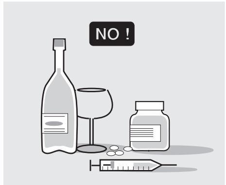
The use of medicines, alcohol and drugs or psychotropic substances notably increases the risk of accidents.
Be sure that you are in good psychophysical conditions and fit for driving and pay particular attention to physical weariness and drowsiness.
Most road accidents are caused by the driver's lack of experience.
NEVER lend the vehicle to beginners and, in any case, make sure that the driver has all the requirements for driving.
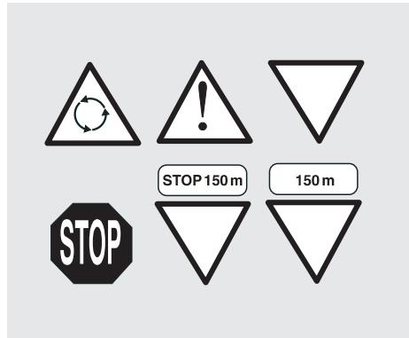
Rigorously observe all road signs and national and local road regulations.
Avoid abrupt movements that can be dangerous for yourself and other people (for example: proceeding on the back wheel, speeding, etc.), and give due consideration to the road surface, visibility and other driving conditions.
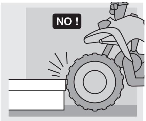
Avoid obstacles that could damage the vehicle or make you lose control.
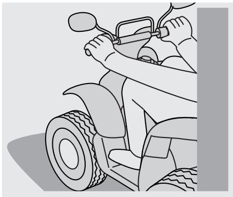
Always drive with both hands on the handlebars and both feet on the footrests (or on the rider's footboards), in the correct driving posture.
Avoid standing up or stretching your limbs while driving.
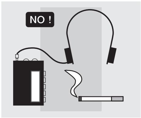
The driver should pay attention and avoid distractions caused by people, things and movements (never smoke, eat, drink, read, etc.) while driving.
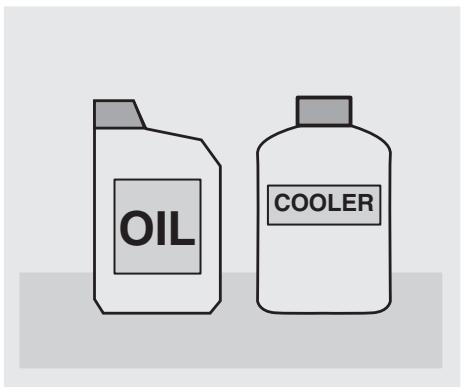
Use only the vehicle's specific fuels and lubricants indicated in the "LUBRICANT CHART" (page 53); regularly check all fuel, engine oil and transmission oil levels.
If the vehicle has been involved in an accident, make sure that no damage has occurred to the control levers, pipes, wires, braking system and vital parts.
If necessary, have the vehicle inspected by a aprilia Official Dealer who should carefully check the frame, handlebars, suspensions, safety parts and all the devices that you cannot check by yourself.
Always remember to report any malfunction to the technicians to help them in their work.
Never use the vehicle when the amount of damage it has suffered endangers your safety.
Never change the position, inclination or colour of: number plate, direction indicators, lights and horns.
Any modification of the vehicle will result in the invalidity of the guarantee
Any modification of the vehicle and/or the removal of original components can compromise vehicle performance levels and safety or even make it illegal.
We recommend respecting all regulations and national and local provisions regarding the equipment of the vehicle.
In particular, avoid all modifications that increase the vehicle's performance levels or alter its original characteristics.
Never race with other vehicles.
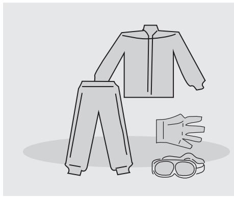
CLOTHING
Wear protective clothing, preferably in light and/or reflecting colours. In this way you will make yourself more visible to the other drivers, thus notably reducing the risk of being knocked down, and you will be more protected in case of fall.
This clothing should be very tight-fitting and fastened at the wrists and ankles; strings, belts and ties should not be hanging loose; prevent these and other objects from interfering with driving by getting entangled with moving parts or driving mechanisms.
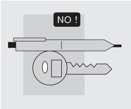
Do not keep objects that can be dangerous in case of fall, for example pointed objects like keys, pens, glass vials etc. in your pockets (the same recommendations also apply to passengers).
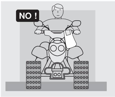
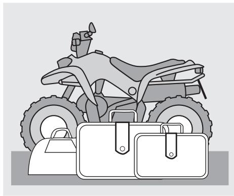
Avoid hanging bulky, heavy and/or dangerous objects on the handlebars, mudguards and forks, because the vehicle might respond more slowly in turns and its manoeuvrability could be unavoidably impaired.
Do not place bags that are too bulky or the crash helmet on the vehicle sides and do not ride with them on, because they could hit people or obstacles, making you lose control of the vehicle.
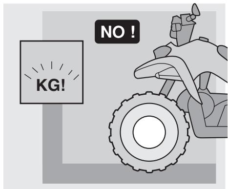
Do not exceed the maximum load allowed for each luggage-rack.
When the vehicle is overloaded, its stability and its manoeuvrability can be compromised.
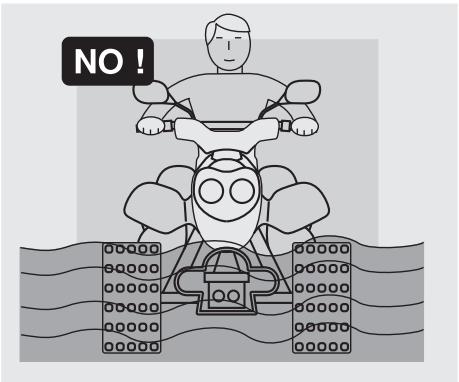
Do not ride the vehicle on a water layer exceeding 10 cm.
After using the vehicle in salted water, wash it with abundant fresh water.

Avoid showing off to ensure your safety. Do not lean on one side in order not to unbalance your weight and make the vehicle take abnormal positions.

Always ride the vehicle in compliance with the safety rules set forth in the present manual, in all riding conditions (rise, descent, turning, etc.) and on any surface.
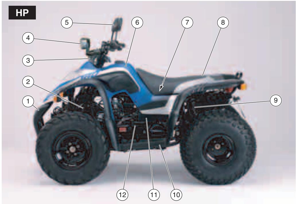
KEY
1) Front guard
2) Left front suspension
3) Front handlebar cover
4) Headlamp
5) Left rear-view mirror
6) Front shield
7) Battery, main fuse
8) Seat
9) Rear shock absorber
10) Left footboard
11) Air cleaner
12) Kick start lever
HP
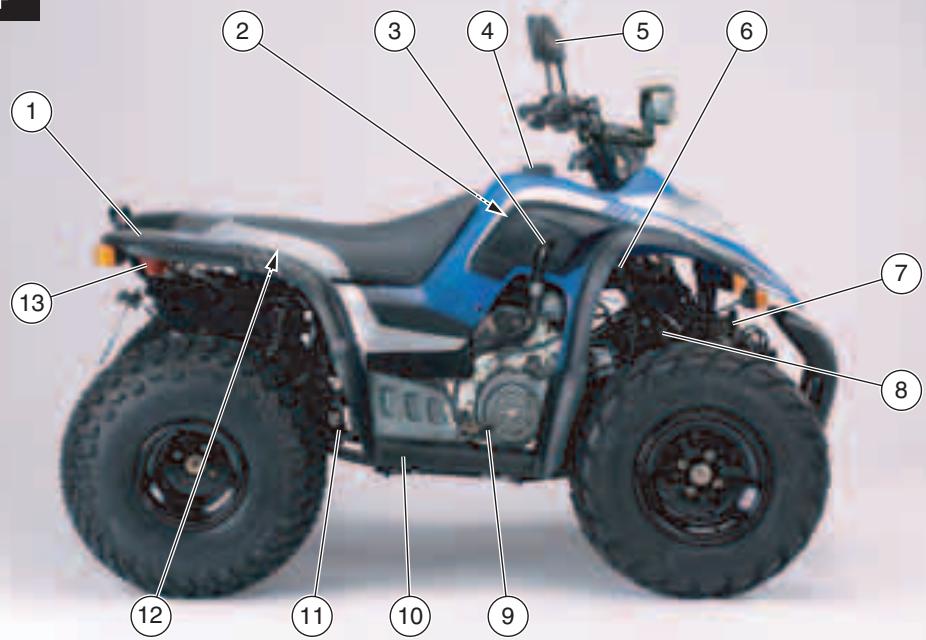
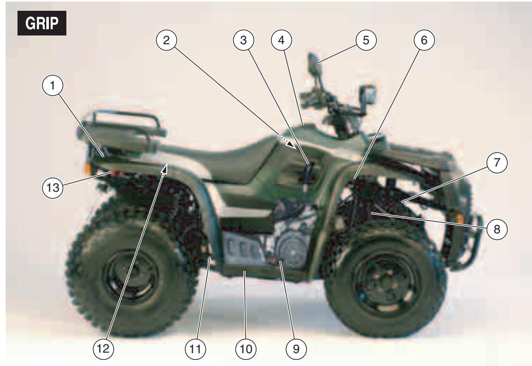
KEY
1) Rear shield
2) Fuel tank
3) Gear lever
4) Fuel tank filler cap
5) Right rear-view mirror
6) Starting relay
7) Horn
8) Right front suspension
9) Front + rear brake pedal
10) Right footboard
11) Drive chain
12) Glove/tool kit compartment
13) Tail light
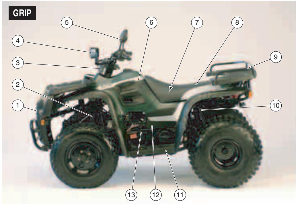
KEY
1) Front guard
2) Left front suspension
3) Front handlebar cover
4) Headlamp
5) Left rear-view mirror
6) Front shield
7) Battery, main fuse
8) Seat
9) Rear luggage rack
10) Rear shock absorber
11) Left footboard
12) Air cleaner
13) Kick start lever
KEY
1) Rear shield
2) Fuel tank
3) Gear lever
4) Fuel tank filler cap
5) Right rear-view mirror
6) Starting relay
7) Horn
8) Right front suspension
9) Front + rear brake pedal
10) Right footboard
11) Drive chain
12) Glove/tool kit compartment
13) Tail light
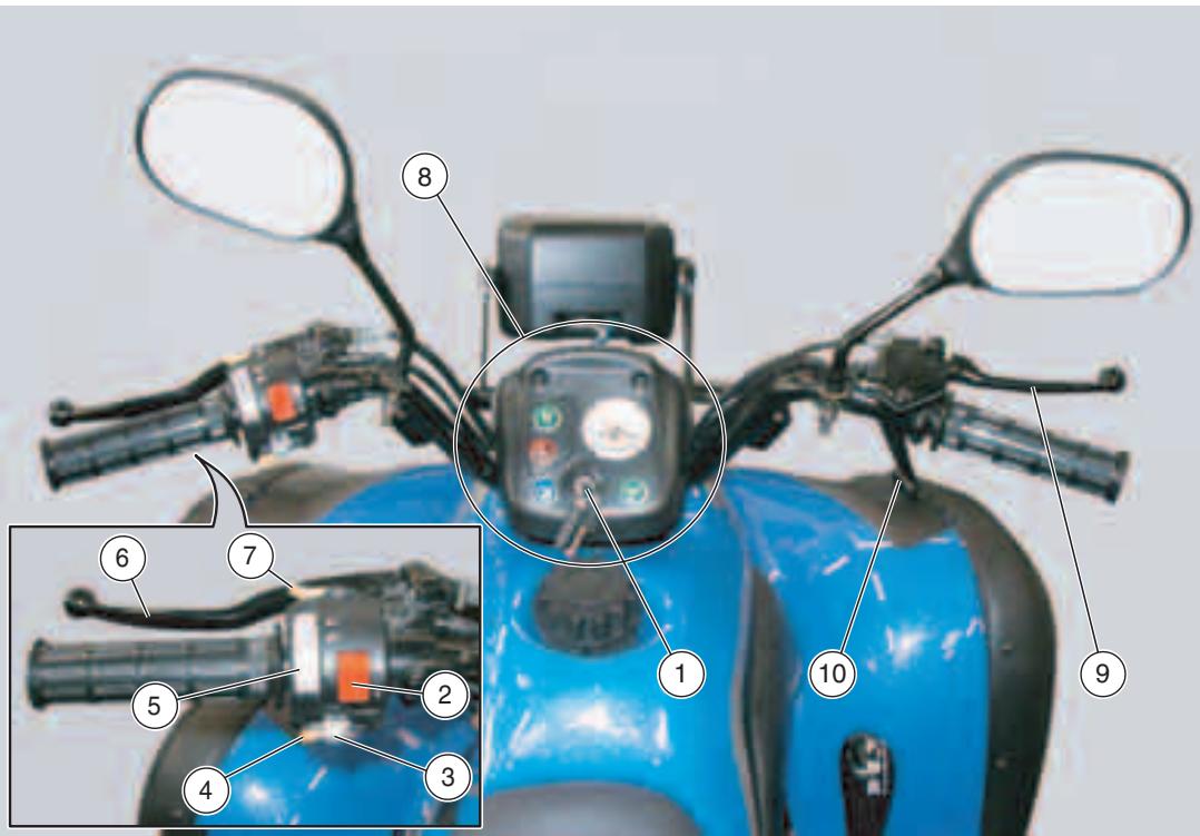
KEY
1) Key-operated ignition switch ( - -)
2) Emergency flasher button (△)
3) Direction indicator switch ( )
4) Horn push button (
5) Dimmer switch (E-D - E-D)
6) Rear brake lever
7) Start push button (③)
8) Warning lights
9) Front brake lever
10) Throttle control
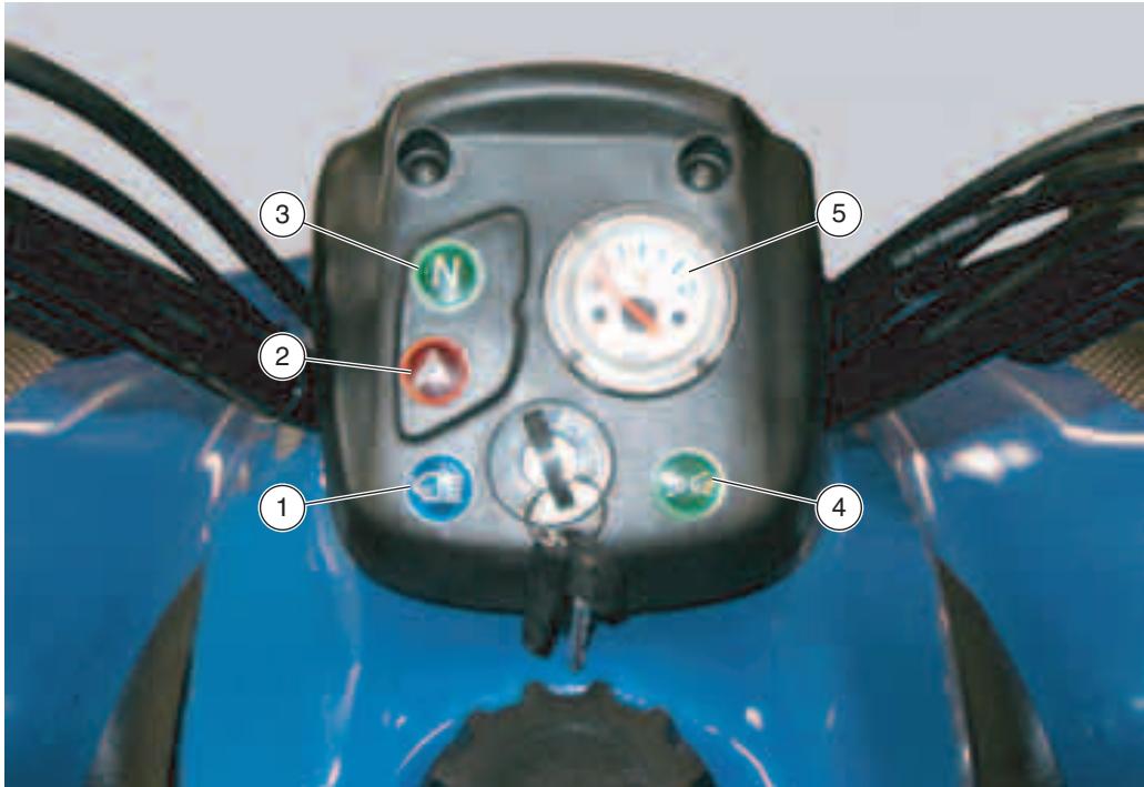
KEY
1) Blue high beam warning light (E D)
2) Red emergency flasher warning light (△)
3) Green neutral warning light (N)
4) Green low beam / parking light warning light (EdoE)
5) Fuel level indicator
MAIN INDEPENDENT CONTROLS
CONTROLS ON LEFT HANDLEBAR
NOTE The electrical parts work only when the ignition switch is in position "O".
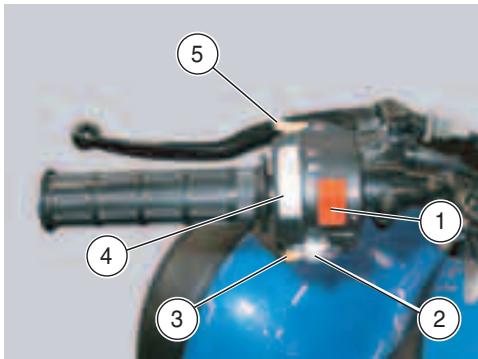
1) EMERGENCY FLASHER BUTTON (△)
When pressed on top (see identifying symbol), it simultaneously enables all direction indicators.
2) DIRECTION INDICATOR SWITCH (ΦΦ)
To indicate the turn to the left, move the switch to the left; to indicate the turn to the right, move the switch to the right.
To turn off the direction indicator, press the switch.
3) HORN BUTTON (▶)
When pressed, it enables the horn.
4) DIMMER SWITCH (D - D)
When it is in position “D” the parking lights and the low beam come on.
When it is in position “ D”, the high beam comes on.
NOTE The dimmer switch is enabled only when the ignition switch in set on
When the start push button " () is pressed, the starter motor makes the engine run.
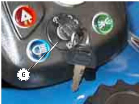
IGNITION SWITCH
The ignition switch (6) is positioned on the vehicle right side, on the front shield.
NOTE The key is used to enable the ignition switch and the dimmer switch.
Two keys are supplied together with the vehicle (one spare key).
NOTE Do not keep the spare key on the vehicle..
| Position | Function | Key removal |
| × | Neither the engine, nor the lights can be switched on. | It is possible to remove the key. |
| ○ | The engine can be switched on. | It is not possible to remove the key. |
| -○- | The parking lights and low beams are switched on; it is possible to turn the high beam on and to start the engine. | The key cannot be removed. |
AUXILIARY EQUIPMENT
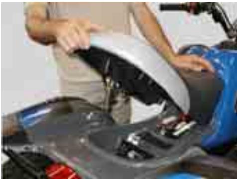
GLOVE/TOOL KIT COMPARTMENT
To reach the glove/tool kit compartment, proceed as follows:
Working from below the rear shield, release the seat latch (pull it backwards) and lift up the seat.
To lock the seat, proceed as follows:
Insert the lower front push rods under the relevant fairing locators.
Position the glove/tool kit compartment lock into its seat and press to make the lock click.
WARNING
Before starting to ride, make sure that the seat is correctly positioned and locked in place.
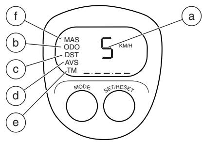
MULTIFUNCTION COMPUTER
The vehicle is equipped with an electronic device to measure the vehicle speed, the elapsed time and to store the distance covered.
CAUTION
When the vehicle is unused, always keep the dial protected against direct sun rays.
CAUTION
Never remove any part of the multifunction computer, battery cover excluded.
CAUTION
Before using the vehicle, make sure that all the parts composing the multifunction computer are correctly assembled.
NOTE Switch the multifunction computer on before starting the vehicle. If this is not the case, the operation of the computer itself could be impaired. The multifunction computer is provided with an automatic shutoff device in case the instrument is left unused for more than 5 minutes.
NOTE When the vehicle is unused or left unattended, always remove the dial from its mount.
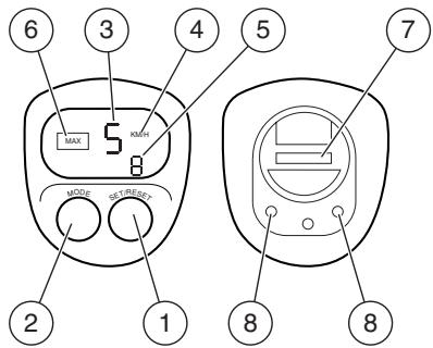
Main components
1) Timer "SET / RESET" push button
2) Function selection "MODE" push button
3) Speed display
4) Units of measurement of the displayed speed
5) Time display
6) Function indicator
7) Battery cover
8) Contacts
Accessories:
- mounting support
speed sensor - clip
-magnet
- steel ring
- rubber seal
-cable tie
- screw
-battery
Setting the units of measurement
To select the desired units of measurements, press push button (1). Confirm by pressing push button (2).
NOTE When setting the units of measurements, the instrument will also display the reset value of the wheel diameter; press push button (1) to set this value to 168 and store the set data by pressing push button (2).
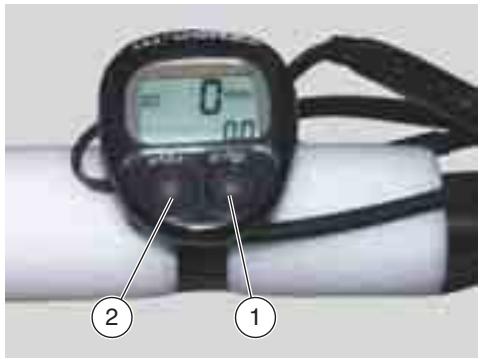
Main functions
Before carrying out any setting or adjustment on the multifunction computer, working from below, fit the dial on its mount on the vehicle.
Press push button (2) repeatedly so as to make the following functions appear in the following order.
To start storing data, press push button (1) (the units of measurement indicator is flashing). To stop data storing, press push button (1) again (the units of measurement indicator is not flashing).
Speed function (a)
The speed function is automatically enabled upon battery installation.
ODO function (b)
The ODO function indicates the total distance covered by the vehicle.
The counter will be automatically reset when reaching 10,000 Km.
NOTE When the multifunction computer battery is removed, all stored values will be deleted.
DST function (c)
The DST function indicates the partial distance covered by the vehicle.
The counter will be automatically reset when reaching 1,000 Km.
To manually reset counter, press push buttons (1) and (2) at the same time.
AVS function (d)
The AVS function indicates the trip average speed.
To reset the stored speed value, press push buttons (1) and (2) at the same time.
TM function (e)
The TM function indicates the time vehicle is being used.
The counter will be automatically reset when reaching 12 hours.
To manually reset counter, press push buttons (1) and (2) at the same time.
MAS function (f)
The MAS function indicates the maximum speed.
To manually reset counter, push buttons (1) and (2) at the same time.
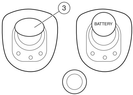
Installing battery
Using a coin, undo the battery cover (3).
Install battery (3 V) inside its compartment.
Take care to position positive pole (+) pointing upwards and negative pole (-) pointing downwards.
Once finished, close battery cover (3) again.
FUEL
WARNING
The fuel used for internal combustion engines is extremely inflammable and in particular conditions it can become explosive.
It is important to carry out the refuelling and the maintenance operations in a well-ventilated area, with the engine off. Do not smoke while refuelling or near fuel vapours, in any case avoid any contact with naked flames, sparks and any other heat source to prevent the fuel from catching fire or from exploding.
Further, prevent fuel from flowing out of the fuel filler, as it could catch fire when getting in contact with the red-hot surfaces of the engine.
In case some fuel has accidentally been spilt, make sure that the area has completely dried before starting the vehicle.
Since fuel expands under the heat of the sun and due to the effects of sun radiation, never fill the tank to the brim. Screw the plug up carefully after refuelling. Avoid any contact of the fuel with the skin and the inhalation of vapours; do not swallow fuel or pour it from a receptacle into another by means of a tube.
DO NOT DISPOSE OF FUEL IN THE ENVIRONMENT.
KEEP AWAY FROM CHILDREN.
Use only premium grade unleaded petrol, min. O.N. 95 (N.O.R.M.) and 85 (N.O.M.M.).
To refuel, proceed as follows:
Undo the tank cap (1) and remove it. FUEL TANK CAPACITY (reserve included): 8
TANK RESERVE: 1.5 ℓ
CAUTION
Do not put additives or other substances into the fuel
If you use a funnel or other similar items, make sure that they are perfectly clean.
WARNING
Do not fill the tank completely; the maximum fuel level must remain below the lower edge of the filler neck (see figure).
Refuel.
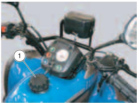
After refuelling:
Screw the fuel tank cap (1).
WARNING
Make sure that the cap is properly closed.
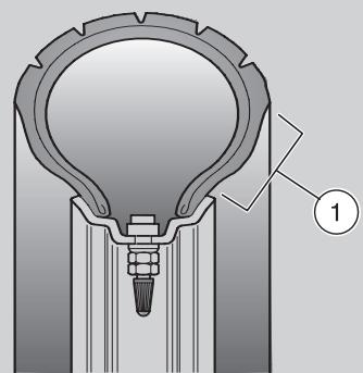
TYRES
This vehicle is provided with tubeless tyres.
NOTE Perform the maintenance operations more often if the vehicle is used in rainy or dusty areas, on uneven surfaces or on racetracks.
WARNING
Always check the inflation pressure at room temperature before using the vehicle.
If the tyres are hot, the measurement is not correct.
If the inflation pressure is too high, the ground unevenness cannot be dampened and is therefore transmitted to the handlebar, thus compromising the driving comfort and reducing the road holding during turns.
If, on the contrary, the inflation pressure is too low, the tyre sides (1) are under greater stress and the tyre itself may slip on the rim or it may become loose, with consequent loss of control of the vehicle.
In case of sudden braking the tyres could even come off the rims.
Too a low pressure could also make the tyre contact the rim, and thus producing cuts on the tyre surface.
Check the conditions of the tyres after the first 2 weeks and then every months.
Finally, be careful while turning: the vehicle could side-skid.
WARNING
Check the surface and the wear of the tyres, since tyres in bad conditions can impair both the grip and the controllability of the vehicle.
Some types of tyres homologated for this vehicle are provided with wear indicators.
There are several kinds of wear indicators. For more information on how to check the wear, contact your Dealer.
Visually check if the tyres are worn and in this case have them changed.
After repairing a tyre, have the wheels balanced.
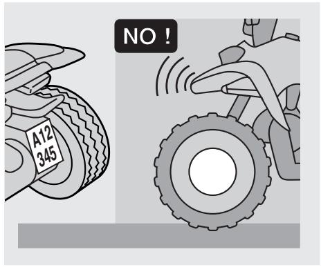
WARNING
The tyres must be replaced with other tyres of the type and model recommended by the manufacturer; the use of tyres different from those prescribed may affect the manoeuvrability of the vehicle.
Do not install tyres with air tube on rims for tubeless tyres and viceversa.
Make sure that the inflation valves always have their sealing caps on, to prevent the tyres from suddenly going flat.
Change, repair, maintenance and balancing operations are very important and therefore they must be performed by qualified technicians with appropriate tools.
For this reason, it is advisable to have the above mentioned operations carried out by a aprilia Official Dealer or by a qualified tyre repairer.
If the tyres are new, they may still be covered with a slippery film: drive carefully for the first miles. If the tyres are old, even if not completely worn out, they may become hard and may not ensure good road holding.
In this case, replace them.
CHECKING THE TRANSMISSION OIL LEVEL
CAUTION
Should you notice oil leaks or malfunctionings, immediately contact a aprilia Authorized Dealer.
DO NOT DISPOSE OF THE OIL IN THE ENVIRONMENT.
To check the transmission oil level, proceed as follows:
Ride the vehicle for a few miles until reaching the standard operating temperature, then stop the engine.
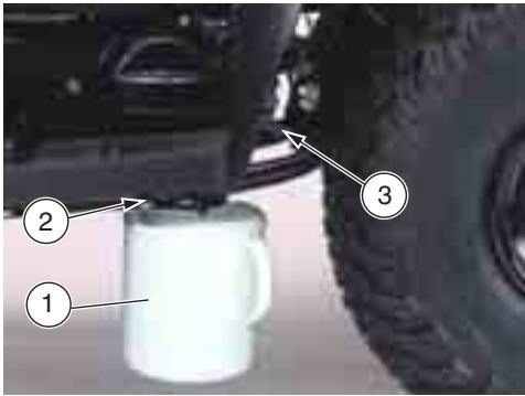
Place a graduated container (1), with a capacity of at least 200 cu. cm, under the drain plug (2).
Undo the oil filler cap (3) and the drain plug (2).
Allow oil to fully drain off the casing.
Measure the oil quantity. Should it be lower than 200 cu. cm, top up by adding the missing quantity, see page 53 (LUBRICANT CHART).
Close the drain plug (2).
Use the oil recovered into the graduated container (1) to top up.
Close the filler cap (3).

CAUTION
Make sure that the drain and filler caps are securely closed and check for oil leaks.
Regularly check for oil leaks at the casing cover seal.
Do not use the vehicle with a poor lubrication or with contaminated or improper lubricants, as these factors make the moving parts wear more rapidly and can lead to severe and irreparable damages.

CHANGING THE TRANSMISSION OIL
CAUTION
In the event of oil leaks or malfunctionings, contact a aprilia Authorized Dealer.
DO NOT DISPOSE OF THE OIL IN THE ENVIRONMENT.
Put it in a sealed container and take it to the filling station where you usually buy it or to an oil salvage center.
Carefully read page 33 (MAINTENANCE).
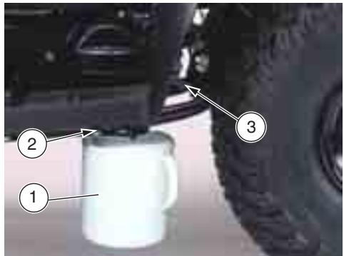
To change the oil, proceed as follows:
Ride the vehicle for a few miles until reaching the standard operating temperature, then stop the engine.
Place a graduated container (1), with a capacity of at least 200 cu. cm, under the drain plug (2).
Undo the oil filler cap (3) and the drain plug (2).
Allow oil to fully drain off the casing.
Tighten the drain plug and pour 200 cu. cm of oil into the tank, see page 53 (LUBRICANT CHART).
Tighten the filler cap (3).
CAUTION
Make sure that the drain and filler caps are securely closed and check for oil leaks.
Regularly check for oil leaks at the casing cover seal.
Do not use the vehicle with a poor lubrication or with contaminated or improper lubricants, as these factors make the moving parts wear more rapidly and can lead to severe and irreparable damages.
CHECKING THE ENGINE OIL LEVEL
CAUTION
In case of oil leaks or malfunctioning, immediately contact a aprilia Official Dealer.
DO NOT DISPOSE OF THE OIL INTO THE ENVIRONMENT
To check engine oil level, proceed as follows:
Ride the vehicle for a few miles until reaching the standard operating temperature, then stop the engine.
Stop the vehicle for a few minutes to allow oil to settle down.
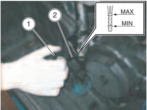
Undo the oil filler cap (1) and clean the rod (2).
Screw the cap (1) again.
Undo the oil filler cap (1) and slide out the rod (2).
Check that the oil level on the rod is between the MIN and MAX reference marks (see figure).
Should the level be lower than the MIN mark, top up by adding the missing quantity, see page 53 (LUBRICANT CHART).
Close the filler cap (1).

CAUTION
Make sure that the drain and filler caps are securely closed and check for oil leaks.
Regularly check for oil leaks at the casing cover seal.
Do not use the vehicle with a poor lubrication or with contaminated or improper lubricants, as these factors make the moving parts wear more rapidly and can lead to severe and irreparable damages.
CHANGING THE ENGINE OIL
CAUTION
In the event of oil leaks or malfunctionings, contact a aprilia Authorized Dealer.
DO NOT DISPOSE OF THE OIL INTO THE ENVIRONMENT
Put it in a sealed container and take it to the filling station where you usually buy it or to an oil salvage center.
Carefully read page 33 (MAINTENANCE).
To change the oil, proceed as follows:
Ride the vehicle for a few miles until reaching the standard operating temperature, then stop the engine.
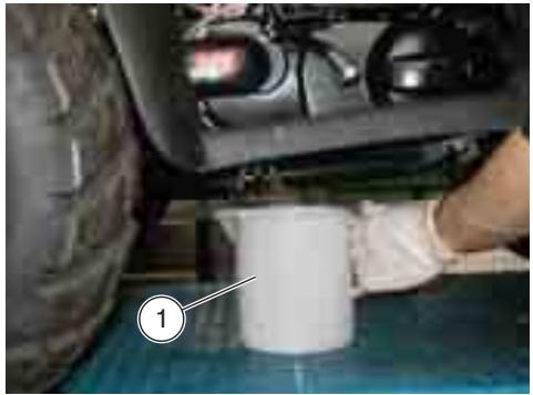
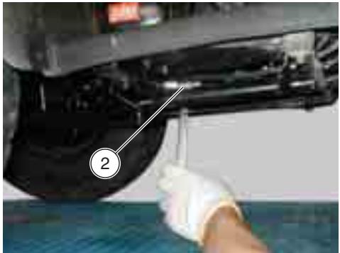
Place a graduated container (1) under the drain plug (2).
Undo the oil filler cap and the drain plug (2).
Allow oil to fully drain off the casing.
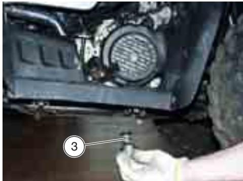
Undo the oil filter (3) and thoroughly clean it.
Refit and tighten filter.
Tighten the drain plug and pour the recommended oil, see page 53 (LUBRICANT CHART).
Tighten the filler cap.
CAUTION
Make sure that the drain and filler caps are securely closed and check for oil leaks.
Regularly check for oil leaks at the casing cover seal.
Do not use the vehicle with a poor lubrication or with contaminated or improper lubricants, as these factors make the moving parts wear more rapidly and can lead to severe and irreparable damages.
EXHAUST SILENCER/EXHAUST TERMINAL
WARNING
Tampering with the noise control system is prohibited.
Owners are warned that the law may forbid:
- any person, other than for purposes of maintenance, repair or replacement to remove or render inoperative any device or element of design incorporated into any new vehicle - for the purpose of noise control - prior to its sale or delivery to the ultimate purchaser or while it is in use;
- the use of the vehicle after such device or element of design has been removed or rendered inoperative by any person.
Check the exhaust silencer and the silencer pipes, making sure that there are neither signs of rust, nor holes and that the exhaust system works effectively.
If the noise produced by the exhaust system increases, immediately contact your aprilia Official Dealer.
CAUTION
Do not touch the exhaust terminal for at least 20 to 30 minutes after use and do not park the vehicle close to inflammable substances or grass to avoid the risk of fire.
INSTRUCTIONS FOR USE

PRELIMINARY CHECKING OPERATIONS
Before departure, always carry out a preliminary check of the vehicle to make sure that it functions correctly and safely, see the following table PRELIMINARY CHECKING OPERATIONS.
Failure to perform these checking operations can cause severe personal injuries or damages to the vehicle.
Do not hesitate to consult your aprilia Official Dealer in case there is something you do not understand about the functioning of some controls or in case you suspect or discover some irregularities.
It does not take long to carry out a check-up and this operation ensures you much more safety.
NOTE Perform the maintenance operations more often if the vehicle is used in rainy or dusty areas, on uneven surfaces or on racetracks.
PRELIMINARY CHECKING OPERATIONS TABLE
| Component | Check | Page |
| Front and rear brakes | Check the functioning of the control levers. | / |
| Accelerator | Make sure that it works smoothly and that it is possible to open and close it completely, in all steering positions. If necessary, adjust and lubricate it. | 38 |
| Wheel/tyres | Check the tyre surface, the inflation pressure, wear and any damage. Remove any foreign matter that may be stuck in the tread grooves.. | 23 |
| Steering | Make sure that the steering rotates smoothly, without any clearance or slackening | / |
| Fastening elements | Make sure that the fastening elements are not loose. If necessary, adjust or tighten them. | / |
| Drive chain | Check the slack. | 36 |
| Fuel tank | Check the fuel level and top up, if necessary. Check the circuit for leaks. Make sure that the fuel cap is correctly closed. | 22 |
| Lights, warning lights, horn, rear stoplight switch and electric devices | Check the proper functioning of the acoustic and visual devices. Change the bulbs or intervene in case of failure. | 17,44 |
| Suspensions | Check for front and rear suspensions correct operation | 37 |
| Idle speed | Check for engine idle speed proper setting | 38 |
STARTING

WARNING
This vehicle must be used gradually and with the greatest care.
Do not position any object on the handlebar, in order not to hinder the rotation of the handlebar and visibility toward the dashboard.
NOTE Before starting the engine, carefully read chapter "Safe drive", see page 5 (SAFE DRIVE).

WARNING
Exhaust gases contain carbon monoxide, which is extremely toxic if inhaled.
Avoid starting the engine in closed or badly-ventilated rooms.
Failure to observe this warning may cause loss of consciousness or even lead to death by asphyxia.
Get on the vehicle in riding position.
Rotate the key and move the ignition switch to position "O".
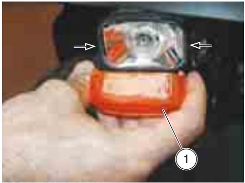
Press the start push button " ( 3 ) " (1) without accelerating and release it as soon as the engine starts.

CAUTION
To avoid battery excessive consumption, do not keep the start button "⑤" pressed for more that fifteen seconds.
If the engine does not start in this lapse of time, wait ten seconds and press the start push button "③" again.

CAUTION
Avoid pressing the start push button "③" when the engine is running, since you may damage the starter motor.
Keep at least one brake lever pulled and do not accelerate until you start.

CAUTION
Never leave abruptly with cold engine. To reduce the emission of polluting substances and the consumption of fuel, warm the engine up by proceeding at low speed for the first miles.
NOTE Should the engine not be started with the starting button, use the kick-start pedal (2).

DEPARTURE AND DRIVE
To leave:
Adjust the inclination of the rear-view mirrors correctly.
Start the engine.
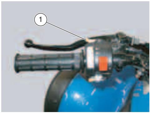
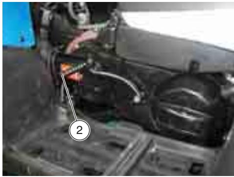
Release the hand brake (2).
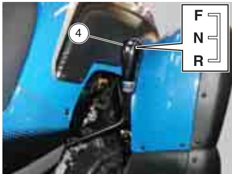
To engage the gear, position the gear lever (4) on (F).
Pull the throttle lever (1). The vehicle will start moving.
Ride at reduced speed for the first miles, in order to warm the engine up.
NOTE To engage the reverse gear, pull the rear brake lever and position the gear lever (4) on (R).
RUNNING-IN
The running-in of the engine is essential to ensure its duration and correct functioning. During running-in, change speed.
In this way the components are first "loaded" and then "relieved" and the engine parts can thus cool down.
Even if it is important to stress the engine components during running-in, take care not to exceed.
NOTE Only after the first 20 of fuel you can expect the best performance levels from the vehicle.
Keep to the following indications:
Do not suddenly or fully open throttles with the engine running at low rpm.
During the first 4 hours of operation pull the brakes with caution, avoiding sharp and prolonged braking. This ensures a correct bedding-in of the brake block friction material on the brake drums.
STOPPING
WARNING
If possible, avoid stopping abruptly, slowing down suddenly and braking at the last moment.Rilasciare la leva accelerator.
Release the throttle lever.
Gradually operate brakes until the vehicle stops.
In case of a brief stop, keep at least one brake pulled.
PARKING
It is very important to choose a suitable parking area, respecting the road signs and the indications given below.
WARNING
Park the vehicle on firm and flat ground. Make sure that the vehicle and especially its red-hot parts do not represent a danger for persons and children. Do not leave the vehicle unattended when the engine is on or the key is inserted into the ignition switch.
To park the vehicle:
Choose a suitable parking area.
Stop the vehicle by turning the ignition switch to "1".
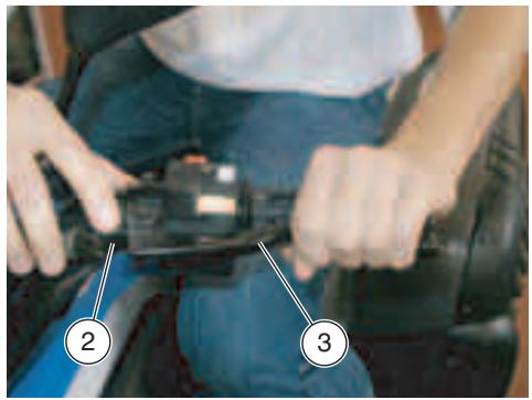
Activate the parking brake by pulling the rear brake control lever (3) and secure it with lock (2).
WARNING
Make sure that the vehicle is stable.
SUGGESTIONS TO PREVENT THEFT
When the vehicle is left unattended, unused or simply parked, NEVER leave the ignition key inserted.
Park the vehicle in a safe place, possibly in a garage or a protected place.
When possible, use an additional anti-theft device.
Make sure that all documents are in order and the road tax has been paid.
Write down your personal data and telephone number in this page, to facilitate the identification of the owner in case of finding after theft.
SURNAME:
NAME:
ADDRESS:
TELEPHONE NO.:
NOTE Very often stolen vehicles are identified thanks to the data written in the use and maintenance manual.
MAINTENANCE
WARNING
Keep fuel and other flammable substances away from the electrical components.
Before beginning any service operations or inspection of the vehicle, switch off the engine and remove the key, wait until the engine and the exhaust system have cooled down and, if possible, lift the vehicle with the proper equipment onto a firm and flat ground.
Before proceeding, make sure that the room in which you are working is properly ventilated.
Keep away from the red-hot parts of the engine and of the exhaust system, in order to avoid burns.
Do not hold any mechanical piece or other parts of the vehicle with your mouth: the components are not edible and some of them are harmful or even toxic.
CAUTION
If not expressly indicated otherwise, for the reassembly of the units repeat the disassembly operations in reverse order.
In case any maintenance operation should be required, it is advisable to use latex gloves.
Routine maintenance operations can usually be carried out by the user, but sometimes specific tools and specific technical skills may be required.
In case periodic maintenance operations, assistance or technical advice are needed, contact a aprilia Official Dealer, who will ensure you prompt and accurate servicing.
Ask your aprilia Official Dealer to test the vehicle on the road after a repair or periodic maintenance operation.
In any case, personally carry out the "Preliminary checking operations" after any maintenance operation, see p. 29 (PRELIMINARY CHECKING OPERATIONS TABLE).
REGULAR SERVICE INTERVALS CHART
Key
① = check and clean, adjust, lubricate or change, if necessary;
② = clean;
③ = change;
④ = adjust.
= perform monthly if the vehicle is used in rainy or dusty areas, or uneven surfaces (off-road).
NOTE Perform the maintenance operations more often if the vehicle is used in rainy or dusty areas, on uneven surfaces or on racetracks..
| Component | After running-in (after 2 weeks) | Every month | Every six months | Every year |
| Throttle and brake cables | ① | ① | ||
| Battery | ① | ① | ||
| Spark plug | ① | |||
| Carburetor/idle speed | ① | ② | ||
| Drive chain | ① | Every 10 hours of operation ① | ||
| Air cleaner | ② | ③ | ||
| Engine oil filter | ② | |||
| Fuel indicator | ① | ① | ||
| Light switch | ① | ① | ||
| Engine oil * | ③ | ③ | ||
| Tyres pressure | ① | Always check before use | ||
| Ignition advance | ④ | |||
| Transmission cables * | ① | ① | ||
| Timing belt | ① | |||
| Drive chain | ① | |||
| Steering tube bearing and steering clearance | ① | ① | ||
| Rings | ① | |||
| Fuel filter | ③ | |||
| Clutch | ① | |||
| Vehicle general operation | ① | ① | ||
| Valve clearance | ④ | ④ | ||
| Greasing | ① | |||
| Stop light switch | ① | ① | ||
| Exhaust pipe / exhaust silencer | ① | |||
| Transmission oil * | ③ | ③ | ||
| Rear belt roller pins | ③ | |||
| Fixed mobile front belt roller | ③ | |||
| Variator rollers | ③ | |||
| Nuts, bolts and screw tightening | ① | ① | ||
| Suspensions * | ① | |||
| Brake drums/blocks | ① | Always check before use | ||
| Fuel line | ① | ① | ||
| We recommend to let maintenance operations on the above parts be carried out by a aprilia Authorized Dealer ONLY | ||||
IDENTIFICATION DATA
It is a good rule to write down the frame and engine numbers in the space provided in this manual.
The frame number can be used for the purchase of spare parts.
NOTE Do not alter the identification numbers if you do not want to incur severe penal and administrative sanctions. In particular, the alteration of the frame number results in the immediate invalidity of the guarantee.
FRAME NUMBER
The frame number is etched on the vehicle front part, over the frame.
Frame no.
ENGINE NUMBER
The engine number is etched on the engine casing, on the vehicle left side.
Engine no.
DRIVE CHAIN
CAUTION
A wrong setting of the chain may damage the chain or the adjuster.
Periodically check the slack and adjust it if necessary.
To adjust and change the chain, contact a aprilia Official Dealer, who will ensure you prompt and accurate servicing.
Incorrect maintenance may cause the untimely wear of the chain and/or damages to the front and/or rear sprocket.
NOTE Perform the maintenance operations more often if the vehicle is used in rainy or dusty areas, on uneven surfaces or on racetracks.
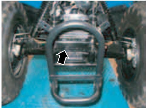
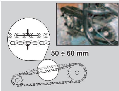
CHECKING THE SLACK
To check the slack, proceed as follows:
Stop the engine.
Remove the chain tensioner and make sure that the vertical oscillation, in an intermediate point between front and rear sprocket in the lower part of the chain, is about 50 - 60 ~mm .
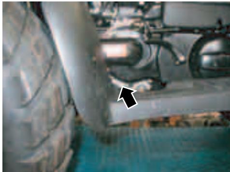
Move the vehicle forwards, in order to be able to check the vertical oscillation of the chain even in other positions; the slack must be constant in all the rotation phases of the wheel.
Refit the chain tensioner.
CAUTION
If in some positions the slack is higher than in others, this means that there are crushed or seized links; in this case, contact a aprilia Official Dealer. To prevent the risk of seizures, lubricate the chain frequently.
If the slack is uniform but without the specified limits, adjust it.
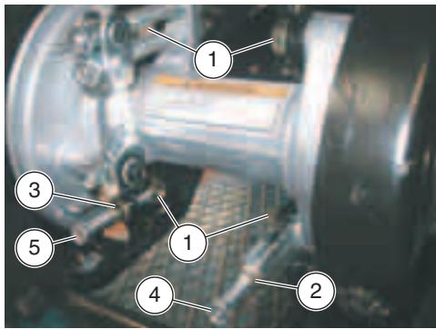
ADJUSTMENT
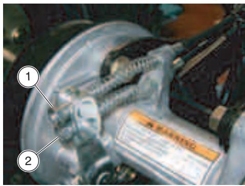
If after the check it is necessary to adjust the chain tension, proceed as follows:
Loosen the 4 screws (1).
Partially undo the check nut (2) on tensioner and check nut (3) on the support screw.
Adjust chain tension turning screw (4).
Adjust support screw (5) position so as to make it rest on tensioner (4).
Once finished, tighten check nuts (2) and (3).
Tighten the 4 screws (1).
Check that chain slack is within the specified limits.
CHECKING THE DRIVE CHAIN, FRONT AND REAR SPROCKET WEAR
Further, check the following parts and make sure that chain, front and rear sprockets do not show:
- damaged rollers;
- loose pins;
- dry, rusty, crushed or seized links;
excessive wear; - front or rear sprocket teeth excessively worn or damaged.
CAUTION
If the chain rollers are damaged and/or the pins are loose, it is necessary to change the whole chain unit (both sprockets and chain).
Lubricate the chain frequently, especially if there are dry or rusty parts.
In case some links are crushed or seized, change chain.
If this is not possible, contact a aprilia Official Dealer, who will provide for changing the chain.
CLEANING AND LUBRICATION
Never wash the chain with water jets, steam jets, high-pressure water jets and highly inflammable solvents.
Wash the chain with diesel oil or kerosene. If it tends to rust quickly, intensify the maintenance intervals.
After washing the chain and letting it dry, lubricate it with the grease recommended in the lubricant chart.
NOTE Do not use the vehicle soon after lubricating the chain, since due to the centrifugal force the lubricant would be sprayed outwards and dirty the surrounding areas..
SUSPENSION CHECKING AND MAINTENANCE
Visually inspect front and rear suspensions. Check for cracks or damage.
With pulled front brake lever, press the handlebar repeatedly, in order to check front suspension proper operation.
Repeat the procedure for the rear suspension by pressing the seat rear part, always with pulled rear brake lever.
In both cases, suspension travel shall be smooth and uniform.
Should some "ends of stroke" be found, contact a aprilia Authorized Dealer.
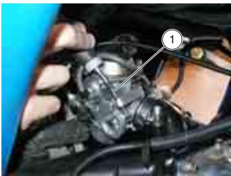
IDLING ADJUSTMENT
Adjust the idling every time it is irregular.
To carry out this operation, proceed as follows:
Ride for a few miles until reaching the normal running temperature.
If necessary, proceed as follows:
Turn the adjusting screw (1).
- BY SCREWING IT (clockwise), you decrease the rpm;
- BY UNSCREWING IT (anticlockwise), you increase the rpm;
Keep the vehicle braked, accelerate and decelerate a few times to make sure that it functions correctly and to check if the idling speed is constant.
NOTE If necessary, contact a aprilia Official Dealer.
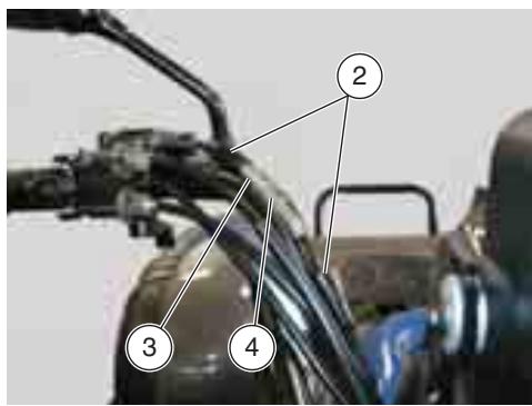
ADJUSTING THE THROTTLE CONTROL
NOTE Perform the maintenance operations more often if the vehicle is used in rainy or dusty areas, on uneven surfaces or on racetracks.
The idle stroke of the throttle grip must be 2-6 mm, measured on the edge of the grip itself.
If not, proceed as follows:
Withdraw the protection elements (2).
Loosen the lock nut (3).
Rotate the adjuster (4) in such a way as to restore the prescribed value.
After the adjustment, tighten the lock nut (3) and check the idle stroke again.
Put back the protection elements (2).
CAUTION
After the adjustment, make sure that the rotation of the handlebar does not modify the engine idling rpm and that the throttle grip returns smoothly and automatically to its original position after being released.
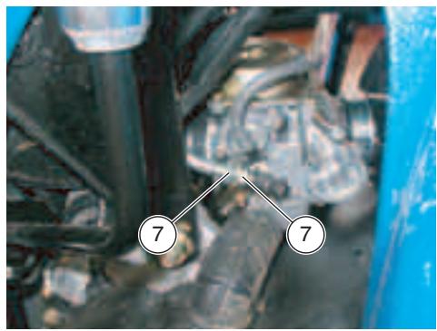
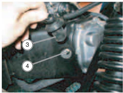
The throttle cable can be adjusted by turning carburetor nuts (7).
Once finished, tighten nuts (7).
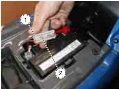
The rear brake lever and pedal travels can be adjusted as follows.
To adjust the lever travel turn nut (1), while to adjust pedal travel turn nut (2).
SPARK PLUG
NOTE Perform the maintenance operations more often if the vehicle is used in rainy or dusty areas, on uneven surfaces or on racetracks.
Periodically remove the spark plug and clean it carefully, removing carbon deposits; change it if necessary.
WARNING
Before carrying out the following operations, let the engine and the silencer cool down until they reach room temperature, in order to avoid burns.
For the removal, proceed as follows:
Remove the cap (3) of the spark plug (4).
Remove any trace of dirt from the spark plug base.
Fit the special spanner provided in the tool kit on the spark plug.
Unscrew the spark plug and extract it from its seat, taking care to prevent dust or other substances from getting inside the cylinder.
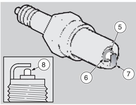
For the check and cleaning:
Key:
centre electrode (5);
- insulating (6);
side electrode (7).
Make sure that there are neither carbon deposits, nor corrosion marks on the electrodes and on the insulating material; if necessary, clean them with a pressurized air jet.
If the spark plug has crackings on the insulating material, corroded electrodes, excessive deposits or the tip (8) of the central electrode (5) is rounded, it must be changed.
CAUTION
When changing the spark plug, check the thread pitch and length.
If the threaded part is too short, the carbon deposits will accumulate on the thread seat, and therefore the engine may be damaged during the installation of the right spark plug.
Use the recommended type of spark plugs only, see page 50 (TECHNICAL DATA), in order not to compromise the life and performance of the engine.
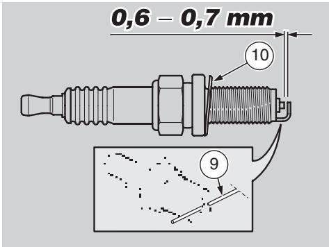
To check the spark plug gap, use a wire thickness gauge (9) to avoid damaging the platinum covering.
Check the spark plug gap with a wire thickness gauge (9).
CAUTION
Do not try to recover the spark plug gap in any way.
The gap must be 0.6 - 0.7 mm, otherwise it is necessary to change the spark plug.
Make sure that the washer (10) is in good conditions.
For the installation:
With the washer (10) on, screw the spark plug by hand in order not to damage the thread.
Tighten the spark plug by means of the spanner you will find in the tool kit, giving it half a turn to compress the washer.
Spark plug driving torque: 20 Nm (2 kgm).
CAUTION
The spark plug must be well tightened, otherwise the engine may overheat and be seriously damaged.
Position the spark plug (4) cap (3) properly, so that it does not come out due to the vibrations of the engine.
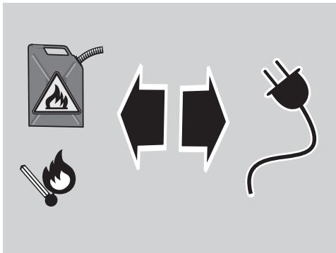
BATTERY
WARNING
Risk of fire.
Keep fuel and other flammable substances away from the electrical components.
Never invert the connection of the battery cables.
Connect and disconnect the battery with the ignition switch in position "1", otherwise some components may be damaged.
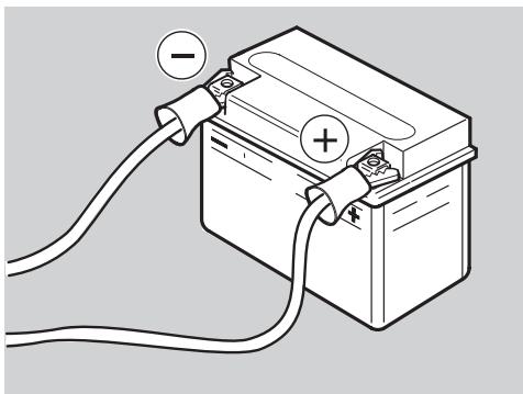
Connect first the positive cable (+) and then the negative cable (-) .
Disconnect following the reverse order.
NOTE This vehicle is provided with a maintenance-free battery and no servicing is necessary, excepting occasional checks and the recharge when required.
Disconnect battery terminals in case of long periods of inactivity.
CHECKING AND CLEANING THE TERMINALS
Carefully read page 41 (BATTERY).
Make sure that the ignition switch is in position.
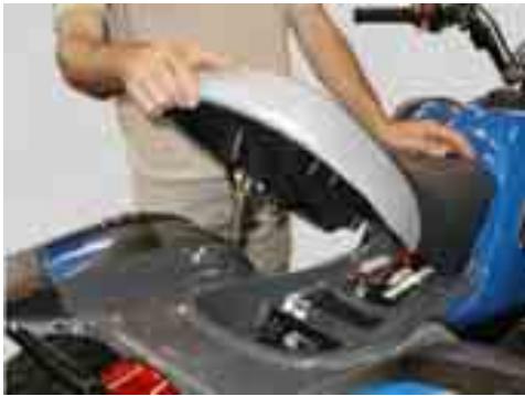
Remove the rider seat, see page 19 (GLOVE/TOOL KIT COMPARTMENT).
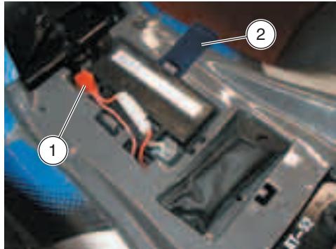
Remove the red protection element (1).
Make sure that the cable terminals and the battery terminals are:
- in good conditions (and not corroded or covered with deposits);
covered with neutral grease or vaseline.
If necessary, proceed as follows:
Remove the battery, see page 41 (REMOVING THE BATTERY).
Brush the cable terminals and the battery terminals with a wire brush, in order to eliminate any trace of corrosion.
Install the battery, see page 43 (INSTALLING THE BATTERY).
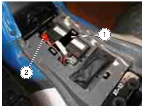
REMOVING THE BATTERY
Make sure that the ignition switch is in position "8".
Remove the rider seat.
Unscrew and remove the screw on the negative terminal (-).
Move the negative cable on the side.
Remove the red protection element (1).
Unscrew and remove the screw on the positive terminal (+) .
Move the positive cable on the side.
Remove the seal (2) that locks the battery.
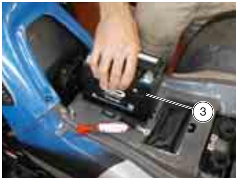
Grasp the battery (3) firmly and remove it from its compartment by lifting it.
WARNING
Once it has been removed, the battery must be stored in a safe place and kept away from children.
Position the battery on a flat surface, in a cool and dry place.
WARNING
At reassembly, connect the cable on the positive terminal (+) first and then that on the negative one (-) .
Put back the rider seat.
CHECKING THE ELECTROLYTE LEVEL
The vehicle is equipped with a maintenance-free battery, which does not require any check of the electrolyte level.
RECHARGING THE BATTERY
Carefully read page 41 (BATTERY).
CAUTION
Do not remove the battery plugs: without plugs the battery may be damaged.
Remove the battery.
Prepare an appropriate battery charger.
Set the charger for the desired type of recharge.
Connect the battery with a battery charger.
WARNING
During the recharging or the use, make sure that the room is properly ventilated and avoid inhaling the gases released during the recharging.
Switch on the battery charger.
WARNING
Reassemble the battery only 5 to 10 minutes after disconnecting the recharge apparatus, since the battery continues to produce gas for a short lapse of time.
INSTALLING THE BATTERY
Make sure that the ignition switch is in position "X".
Remove the rider seat.
NOTE The battery must be positioned in its compartment with the terminals directed towards the right side of the vehicle.
Put the battery in its compartment.
Put back the seal (1) that locks the battery.
WARNING
Upon reassembly, connect first the positive cable (+) and then the negative cable (-) .
Connect the positive terminal (+) by means of the screw.
Connect the negative terminal (-) by means of the screw.
Cover the terminals of the cables and of the battery with neutral grease or vaseline.
Put back the red protection element (2).
Put back the rider seat.
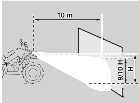
ADJUSTING THE VERTICAL HEADLIGHT BEAM
NOTE To check the direction of the headlight beam, specific procedures must be adopted, in accordance with the regulations in force in the country where the vehicle is used.
To rapidly check the headlight beam correct alignment, place the vehicle at a distance of ten meters from a vertical wall. Make sure that the ground is even and flat.
Switch the low beams on, sit on the vehicle and check that the beam projected on the wall is just slightly below the headlight
horizontal line (about 9/10th of the total height).
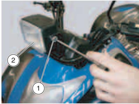
To adjust the headlight beam:
Loosen the two headlamp (2) screws (1) from their mounts and adjust the headlamp position.
Once you have reached the desired aim of the headlight beam, tighten screws (1).
After the adjustment:
WARNING
Make sure that the vertical adjustment of the headlight beam is correct.
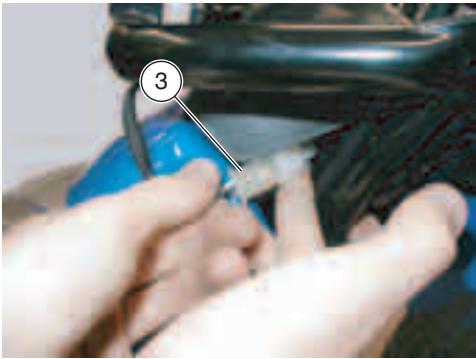
CHANGING THE HEADLIGHT BULB
To replace, proceed as follows:
Make sure that the ignition switch is turned to "1".
Take the connector (3) out of the front handlebar and disconnect it from main wiring.
Undo the screws (1) and remove the headlight body from vehicle.
Undo and remove the two screws (4) of the bulb shells and remove the headlight body (5).
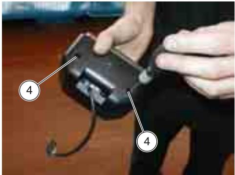
Turn the bulb holder (6) counterclockwise to detach it from the headlight body (5).
Remove the damaged bulb and replace it with a new one of the same type.
NOTE After having changed the bulb, adjust the vertical headlight beam, see page 43 (ADJUSTING THE VERTICAL HEADLIGHT BEAM).
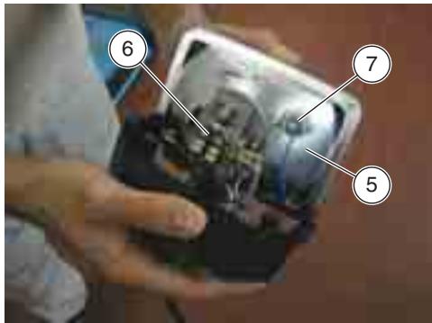
To remove the parking light bulb, proceed as follows:
Grasp the bulb holder (7), pull it and take it out of its location.
Slide out the parking light bulb and replace it with a new one of the dame type.
BULBS
WARNING
Risk of fire.
Keep fuel and other flammable substances away from the electrical components.
CAUTION
Before changing a bulb, move the ignition switch to position "×" and wait a few minutes, so that the bulb cools down.
Change the bulb wearing clean gloves or using a clean and dry cloth.
Do not leave fingerprints on the bulb, since these may cause its overheating and consequent breakage.
If you touch the bulb with bare hands, remove any fingerprint with alcohol, in order to avoid any damage.
DO NOT FORCE THE ELECTRIC CABLES.
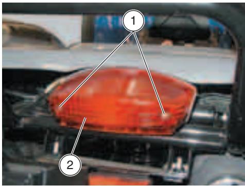
CHANGING THE FRONT AND REAR DIRECTION INDICATOR BULBS
Carefully read page 45 (BULBS).
Using a screwdriver, lever at the sides of the indicator mount to remove the protection screen (1).
CAUTION
While removing the protection screen, proceed carefully in order not to break the cog.
Extract the damaged bulb and correctly install a new bulb of the same type.

NOTE Upon reassembly, correctly position the protection screen (1) on the indicator mount.
CHANGING THE TAIL LIGHT BULB
Carefully read page 45 (BULBS).
To replace, proceed as follows:
Undo the two tail light screws (1).
Remove the lens (2).
Remove the damaged bulb and replace it with a new one of the same type.
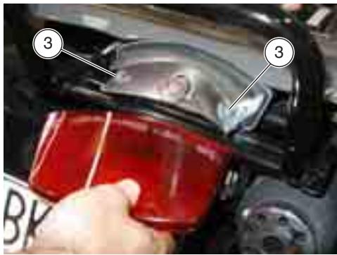
NOTE After having replaced the bulb, be sure to correctly position the lens (2) by making the retaining screw holes match with those (3) on the tail light mount.
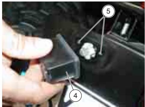
CHANGING THE NUMBER PLATE LIGHT BULB
Carefully read page 45 (BULBS)
To change, proceed as follows:
Undo the two number plate holder cover (4) screws.
Remove the cover (4).
Remove the damaged bulb and replace it with a new one of the same type.
NOTE After having replaced the bulb, be sure to correctly position the cover (4) by making the retaining screw holes match with those (5) on the tail light mount.
CHANGING THE FUSE
Carefully read page 6 (BASIC SAFETY RULES).
CAUTION
Do not repair faulty fuses.
Never use fuses different from the recommended ones.
The use of unsuitable fuses may cause damages to the electric system or, in case of short circuit, even a fire.
NOTE If a fuse blows frequently, there is probably a short circuit or an overload in the electric system.
If an electric component does not work or works irregularly, or if the vehicle fails to start, it is necessary to check the fuse.
For the check, proceed as follows:
Remove the rider seat, see page 19 (GLOVE/TOOL KIT COMPARTMENT).
Disconnect the battery cables, see page 41 (REMOVING THE BATTERY).
Slide out the fuse (2).
NOTE Before changing the fuse, try to find out the cause of the problem, if possible.
If damaged, replace the fuse with one having the same amperage.
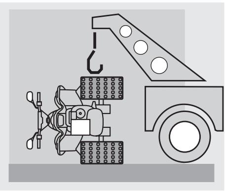
TRANSPORT
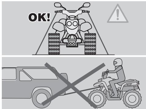
NOTE During transport, the vehicle must be firmly anchored and the hand brake shall be pulled.
CAUTION
In case of failure, do not tow the vehicle, but ask for assistance.
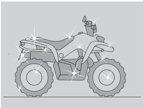
Clean the vehicle frequently if it used in particular areas or conditions, such as:
- Polluted areas (cities and industrial areas).
- Areas characterized by a high percentage of salinity and humidity (sea areas, hot and humid climates).
- Particular conditions (use of salt and anti-ice chemical products on the roads during the winter).
- Avoid leaving deposits of industrial and polluting powders, tar spots, dead insects, bird droppings, etc. on the body.
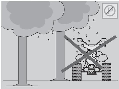
- Avoid parking the vehicle under trees, since in some seasons residues, resins, fruits or leaves fall down, which contain substances that may damage the paint.
WARNING
After the vehicle has been washed, its braking functions could be temporarily impaired because of the presence of water on the grip surfaces.
Calculate long braking distances to avoid accidents.
Brake repeatedly to restore normal conditions.
Carry out the preliminary checking operations, see page 28 (PRELIMINARY CHECKING OPERATIONS).
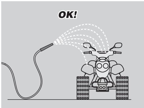
To remove dirt and mud from the painted surfaces use a low-pressure water jet, carefully wet the dirty parts, remove mud and filth with a soft car sponge impregnated with a lot of water and shampoo (2 - 4% parts of shampoo in water).
Then rinse with plenty of water and dry with chamois leather.
To clean the outer parts of the engine use a degreaser, brushes and wipers.
CAUTION
To clean the lights, use a sponge soaked with water and a neutral detergent, rubbing the surfaces delicately and rinsing frequently with plenty of water.
Polish with silicone wax only after
having carefully washed the vehicle.
Do not use polishing pastes on matt paints.
Do not wash the vehicle under the sun, especially during the summer, when the body is still warm, since if the shampoo dries before being rinsed away, it can damage the paint.
Do not use liquids at a temperature exceeding 40^ to clean the plastic components of the vehicle.
CAUTION
Do not direct high-pressure water or air jets or steam jets on to the following components: wheel hubs, controls on the right and left side of the handlebar, bearings, brake master cylinders, instruments and indicators, exhaust pipes, glove/tool kit compartment, ignition switch, radiator fins, fuel cap, lights and electric connections.
Do not use alcohol, petrol or solvents to clean the rubber and plastic parts and the seat: use only water and mild soap.
WARNING
Do not apply protection waxes onto the seat, in order not to make it too slippery.
LONG PERIODS OF INACTIVITY
After a long period of inactivity of the vehicle some precautions are necessary to avoid any problem.
Further, it is important to carry out the necessary repairs and a general check up before the period of inactivity, since you could forget to carry them out later.
Proceed as follows:
Remove the battery, see page 41 (REMOVING THE BATTERY).
Wash and dry the vehicle, see page 48 (CLEANING).
Polish the painted surfaces with wax.
Inflate the tyres, see page 23 (TYRES).
Place the vehicle in an unheated, nothumid room, away from sunlight, with minimum temperature variations.
Position and tie a plastic bag on the final pipe of the exhaust silencer, in order to prevent moisture from getting into it.
Cover the vehicle avoiding the use of plastic or waterproof materials.
AFTER A PERIOD OF INACTIVITY
NOTE Withdraw the plastic bag from the exhaust silencer.
Uncover and clean the vehicle, see page 48 (CLEANING).
Check the charge of the battery, see page 42 (RECHARGING THE BATTERY) and install it, see page 43 (INSTALLING THE BATTERY).
Refill the fuel tank, see page 22 (FUEL).
Carry out the preliminary checking operations, see page 28 (PRELIMINARY CHECKING OPERATIONS).
WARNING
Have a test ride at moderate speed in a low-traffic area
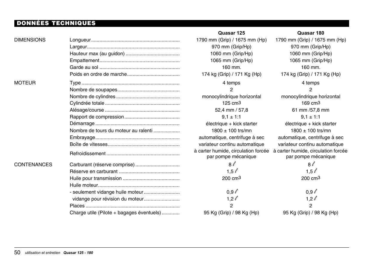
TECHNICAL DATA
| Quasar 125 | Quasar 180 | ||
| DIMENSIONS | Length | 1790 mm (Grip) / 1675 mm (Hp) | 1790 mm (Grip) / 1675 mm (Hp) |
| Width | 970 mm (Grip/Hp) | 970 mm (Grip/Hp) | |
| Max. height (to handlebars) | 1060 mm (Grip/Hp) | 1060 mm (Grip/Hp) | |
| Wheel base | 1065 mm (Grip/Hp) | 1065 mm (Grip/Hp) | |
| Min. ground clearance | 160 mm | 160 mm | |
| Weight ready for starting | 174 kg (Grip) / 171 Kg (Hp) | 174 kg (Grip) / 171 Kg (Hp) | |
| ENGINE | Type | 4-stroke | 4-stroke |
| Number of valves | 2 | 2 | |
| Number of cylinders | horizontal single cylinder | horizontal single cylinder | |
| Total displacement | 125 cu. cm | 169 cu. cm | |
| Bore/stroke | 52.4 mm / 57.8 | 61 mm / 57.8 mm | |
| Compression ratio | 9.1 ± 1:1 | 9.1 ± 1:1 | |
| Starting | electric + kick starter | electric + kick starter | |
| Engine idling rpm | 1,800 ± 100 rpm | 1,800 ± 100 rpm | |
| Clutch | automatic, dry centrifugal | automatic, dry centrifugal | |
| Gearbox | automatic variable transmission | automatic variable transmission | |
| Cooling | wet casing, forced circulation via mechanical pump | wet casing, forced circulation via mechanical pump | |
| CAPACITY | Fuel (reserve included) | 8 l | 8 l |
| Fuel reserve | 1.5 l | 1.5 l | |
| Transmission oil | 200 cu. cm | 200 cu. cm | |
| Engine oil | |||
| - engine oil change only | 0.9 l | 0.9 l | |
| - change for engine overhaul | 1.2 l | 1.2 l | |
| Seats | 2 | 2 | |
| Vehicle max. load (driver + possible luggage) | 95 Kg (Grip) / 98 Kg (Hp) | 95 Kg (Grip) / 98 Kg (Hp) | |
| TRANSMISSION | Variator | automatic continuous | automatic continuous |
| Primary | with trapezoidal belt | with trapezoidal belt | |
| Ratios | |||
| - minimum for continuous variable transmission | 3 | 3 | |
| - maximum for continuous variable transmission | 0.789 | 0.789 | |
| Secondary | gear-type | gear-type | |
| Final | belt-type | belt-type | |
| CARBURETTOR | Model | ||
| - type | Walbro | Walbro | |
| Choke tube | Ø 22 mm | Ø 22 mm | |
| FUEL SUPPLY | Fuel | premium grade unleaded petrol, number DIN 51607, min. O.N. 95 (N.O.R.M.) and 85 (N.O.M.M.). | |
| FRAME | Type | tube | tube |
| SUSPENSIONS | Front | with independent arms | with independent arms |
| Rear | hydraulic monoshock absorber | hydraulic monoshock absorber | |
| BRAKES | Front | Ø 110 mm mechanically driven drum brake | Ø 110 mm mechanically driven drum brake |
| Rear | Ø 130 mm mechanically driven drum brake | Ø 130 mm mechanically driven drum brake | |
| WHEEL RIMS | Type | steel | steel |
| Front | 10x5.5 | 10x5.5 | |
| Rear | 8x8.0 | 8x8.0 | |
| TYRES | Type | tubeless | tubeless |
| Front | 21 x 7-10 | 21 x 7-10 | |
| Rear | 22 x 11-8 | 22 x 11-8 | |
| AS AN ALTERNATIVE | |||
| Front | AT 21 x 7-10 | AT 21 x 7-10 | |
| Rear | AT 21 x 10-8 | AT 21 x 10-8 | |
| Front inflating pressure | 20-25 kPa (0.20 - 0.25 bar) | 20-25 kPa (0.20 - 0.25 bar) | |
| Rear inflating pressure | 30 kPa (0,30 bar) | 30 kPa (0,30 bar) | |
| IGNITION | Type | C.D.I. | C.D.I. |
| Ignition advance | 15° ± 2° | 13° ± 2° | |
| SPARK PLUG | Standard | NGK CR8HSA | NGK CR8HSA |
| Spark plug gap | 0.6 - 0.7 mm | 0.6 - 0.7 mm | |
| ELECTRIC SYSTEM | Battery | 12 V - 9Ah | 12 V - 9Ah |
| Fuse | 15A | 15A | |
| Generator (with permanent magnet) | 12 V - 110W | 12 V - 110W | |
| BULBS | Front parking light | 12 V - 5W | 12 V - 5W |
| Low/high beam | 12 V - 35/35W | 12 V - 35/35W | |
| Direction indicators | 12 V - 10W | 12 V - 10W | |
| Rear parking lights/Stoplight | 12 V - 5/21W | 12 V - 5/21W | |
| Number plate light | 12 V - 5W | 12 V - 5W | |
LUBRICANT CHART
Transmission fluid (recommended): PONTIAX HD SAE 85W-140 or Agip ROTRA MP 85W-140.
As an alternative to recommended fluids it is possible to use high-quality fluids having equal or higher ratings with respect to A.P.I. GL-5 specifications
Engine oil (recommended): SUPERMOTOROIL SAE 15W-40 or Agip F1 SUPERMOTOROIL 15W-40.
As an alternative to recommended oil, it is possible to use high-quality oil having equal or higher ratings with respect to A.P.I. SJ/CF specifications.
Bearings and other parts needing lubrication (recommended): AUTOGREASE MP or Agip GREASE 30.
As an alternative to recommended fluids it is possible to use high-quality grease for bearings, temperature range -30^ + 140^ , floating point 150^ + 230^ , highly corrosion protectant, good waterproof and oxidization-proof ability.
Battery terminals protection: Neutral grease or vaseline.
Chain spray grease (recommended): CHAIN SPRAY or Agip CHAIN LUBE.
ITHE VALUE OF SERVICE
aprilia
Thanks to ongoing technical updates and product-specific technical training, aprilia Authorised Network engineers are familiar with every detail of this vehicle and have the special equipment required for correct maintenance and repair.
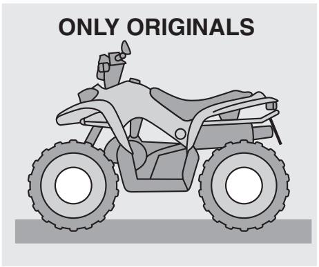
A vehicle kept in sleek running order is a reliable vehicle. Pre-ride checks, proper maintenance at the recommended intervals and using aprilia Original Parts only are other key factors!
To find contact information of the Official Dealer and/or Service Centre nearest you, please consult the Yellow Pages or the map provided at our web site :
www.aprilia.com
When you demand aprilia Original Parts, you are purchasing products that have been developed and tested as early as the vehicle design stage. aprilia Original Parts systematically undergo strict quality control procedures to ensure total reliability and long service life.

APRILIA
via G. Galilei, 1 - 30033 Noale (VE) Italy
Tel. +39(0)41 5829111 - Fax +39(0)41 441054 - Servizio Clienti aprilia +39(0)41 5786269

APRILIA WORLD SERVICE UK branch

APRILIA MOTORRAD
15 Gregory Way - SK5 7ST Stockport - Cheshire
Tel. 0044-161 475 1800 - Fax 0044-161 475 1825 - Email: emcaprilia@aol.com
Am Seestern 3 - D-40547 - Dusseldorf
Tel. 0049-211-59018-00 - Fax 0049-211-5901819

APRILIA WORLD SERVICE B.V.

APRILIA WORLD SERVICE
Succursale en Espana
no. 1 Long Mile Road - Dublin 12
Tel. 00353-1-4566222 - Fax. 00353-1-4756461 - Email:sales@bikeworld.ie

HARO SKANDINAVIA A.S.
Kjorbekkdalen 6 - 3735- Skien
Tel. 0047-35506780 - Fax. 0047-35506781 - E-mail:tore@aprilia.no

MOTOMAX MOTORLU ARACLAR SAN.VETIC.A.S.
Kore Sehitleri Cad. No. 42 - 80300 - Zincirlikuyu - Istanbul
Tel. 0090-212-3360058 - Fax. 0090-212-3360057 - Email:sule@interline.com.tr

MILLE MOTOR KFT. (sede operativa)
Hold utca 23 - H-1054 - Budapest
Tel. 0036-1-3329938 - Fax. 0036-1-2693044 - Email: bertinus@elender.hu

MILFA IMPORTACAO EXPORTACAO LDA.
Av. Da Republica 692-4450 - Matosinhos
Tel. 00351-229382450 - Fax. 00351-229371305 - Email: milfa@meganet.pt

APRILIAHELLAS
Rizareiou - 15233 - Halandri
Tel. 0030-210-6898056 - Fax. 0030-210-6898056 - Email: aprilia@otermail.gr

MOHAG A.G.
Bernerstrasse Nord 202 - 8064 - Zurigo
Tel. 0041-1-4348686 - Fax 0041-1-434 8606 - Email: info@mohag.ch

N.V./S.A.RAD
Landegemstraat 4 - Industriegebied - B-9031 - Drongen-Baarle Tel. 0032-9-2829410 - Fax. 0032-9-2810012 - Email: aprilia@rad.be

T.M.P.
Hammervej 32 - 7900 - Nikobing Mors
Tel. 0045-97-722233 - Fax. 0045-97-722143/33 - Email: thomas@aprilia.dk

TUONTI NAKKILA/OY
P.o.B. 18 - 29250 - Nakkila
Tel. 00358-2-5352500 - Fax. 00358-2-5372793 - Email: satu.saarinen@aprilia.fi

RO GROUP INT.(sede operativa)
Str. Depozitelor 41-43 Jud. Arges - Pitesti
Tel. 0040-248211004 -Fax. 0040-248211004 - Email: marian.ion@rogroup.ro

Z.A.O. ITALMOTO (sede operativa)
Ul. Preobragenskaya 5/7 - 107076 - Mo - Moscow
Tel. 007-095-208 2557 - Fax. 007-095-208 3228 - Email: italmoto@mtu-net.ru

APRILIA U.S.A., INC. (Sede operativa)
109 Smoke Hill Lane Suite 190 - GA 30188 - Woodstock
Tel. 001-770-592-2261 - Fax. 001-770-592-4878

APRILIA JAPAN CORP.
SHINYOKOHAMAMEGURO BLDG. 3-22-5 SHINYOKOHAMA KOUHOKU-KU 222-0033
YOKOHAMA-SHI KANAGAWA (J) -Tel. 0081-454772632 - Fax 0081-454772605 - Email: m-okuyama@apriliajapan.co.jo

JOHN SAMPLE GROUP PTY LTD.
8 Sheridan Close - NSW 2214 - Milperra - Sydney
Tel. 0061-2-97722666 - Fax. 0061-2-97742321 - Email: doreilly@jsg.com.au

No. 281 Jungshing North Street - Sanchung City - 241 - Taipei
Tel. 00886-2-85111156 - Fax. 00886 2 85111148 - Email: taiwan.eisyu@msa.hinet.net

AL-RADWAN INTERNATIONAL GROUP
Block 1, Street 13, Plot 107 45703 - Shuwaikh Industrial
Tel. 00965-4828072 - Fax. 00965-4828073 - Email: alradwan@mail.com

ACCESS INTERNATIONAL FOR
TRADING SARL.
Diamond Tower, 10th Floor P.O.B. 13 - Verdun, near Mandarine Beirut
Tel. 00961-1797333 - Fax: 00961-1798333 - Email: access_in@ hotmail.com

PT. MOTOR MEGA PERFORMA
aprilia s.p.a. wishes to thank its customers for the purchase of this vehicle:
- Do not dispose of oil, fuel, polluting substances and components in the environment.
- Do not keep the engine running if it isn't necessary.
- Avoid disturbing noises.
- Respect nature
- APRILIA WORLD SERVICE UK branch
- APRILIA MOTORRAD
- APRILIA WORLD SERVICE B.V.
- APRILIA WORLD SERVICE
- Succursale en Espana
- HARO SKANDINAVIA A.S.
- AUSPUFFTOPF/SCHALLDÄMPFER
- GEFAHR
- WARNING
- CAUTION
- TECHNICAL INFORMATION
- WARNING - PRECAUTIONS - GENERAL ADVICE
- SAFETYWARNINGS
- TABLE OF CONTENTS
- BASIC SAFETY RULES
- CLOTHING
- KEY
- HP
- MAIN INDEPENDENT CONTROLS
- CONTROLS ON LEFT HANDLEBAR
- IGNITION SWITCH
- AUXILIARY EQUIPMENT
- GLOVE/TOOL KIT COMPARTMENT
- MULTIFUNCTION COMPUTER
- Main components
- Accessories:
- Setting the units of measurement
- Main functions
- Speed function (a)
- ODO function (b)
- DST function (c)
- AVS function (d)
- TM function (e)
- MAS function (f)
- Installing battery
- FUEL
- DO NOT DISPOSE OF FUEL IN THE ENVIRONMENT.
- KEEP AWAY FROM CHILDREN.
- To refuel, proceed as follows:
- After refuelling:
- TYRES
- CHECKING THE TRANSMISSION OIL LEVEL
- DO NOT DISPOSE OF THE OIL IN THE ENVIRONMENT.
- CHANGING THE TRANSMISSION OIL
- CHECKING THE ENGINE OIL LEVEL
- DO NOT DISPOSE OF THE OIL INTO THE ENVIRONMENT
- EXHAUST SILENCER/EXHAUST TERMINAL
- INSTRUCTIONS FOR USE
- PRELIMINARY CHECKING OPERATIONS
- STARTING
- DEPARTURE AND DRIVE
- To leave:
- RUNNING-IN
- Keep to the following indications:
- STOPPING
- PARKING
- To park the vehicle:
- SUGGESTIONS TO PREVENT THEFT
- MAINTENANCE
- REGULAR SERVICE INTERVALS CHART
- IDENTIFICATION DATA
- FRAME NUMBER
- ENGINE NUMBER
- DRIVE CHAIN
- CHECKING THE SLACK
- To check the slack, proceed as follows:
- ADJUSTMENT
- CHECKING THE DRIVE CHAIN, FRONT AND REAR SPROCKET WEAR
- CLEANING AND LUBRICATION
- SUSPENSION CHECKING AND MAINTENANCE
- IDLING ADJUSTMENT
- ADJUSTING THE THROTTLE CONTROL
- SPARK PLUG
- For the removal, proceed as follows:
- For the check and cleaning:
- Key:
- For the installation:
- BATTERY
- Risk of fire.
- CHECKING AND CLEANING THE TERMINALS
- Carefully read page 41 (BATTERY).
- If necessary, proceed as follows:
- REMOVING THE BATTERY
- CHECKING THE ELECTROLYTE LEVEL
- RECHARGING THE BATTERY
- INSTALLING THE BATTERY
- ADJUSTING THE VERTICAL HEADLIGHT BEAM
- To adjust the headlight beam:
- CHANGING THE HEADLIGHT BULB
- To replace, proceed as follows:
- To remove the parking light bulb, proceed as follows:
- BULBS
- CHANGING THE FRONT AND REAR DIRECTION INDICATOR BULBS
- CHANGING THE TAIL LIGHT BULB
- CHANGING THE NUMBER PLATE LIGHT BULB
- CHANGING THE FUSE
- TRANSPORT
- Clean the vehicle frequently if it used in particular areas or conditions, such as:
- LONG PERIODS OF INACTIVITY
- Proceed as follows:
- AFTER A PERIOD OF INACTIVITY
- TECHNICAL DATA
- LUBRICANT CHART
- ITHE VALUE OF SERVICE
- aprilia
- www.aprilia.com
Brand : APRILIA
Model : QUASAR 180
Category : Scooter