
AMICO 50 - Scooter APRILIA - Free user manual and instructions
Find the device manual for free AMICO 50 APRILIA in PDF.
| Product type | 50 cc Scooter |
| Brand | APRILIA |
| Model | AMICO 50 |
| Engine | Single-cylinder 2-stroke, air-cooled |
| Displacement | 49 cm³ |
| Bore x stroke | 40 x 39.2 mm |
| Compression ratio | 13:1 |
| Ignition | Electronic CDI |
| Spark plug | NGK BR7 HS, gap 0.5-0.6 mm |
| Carburetor | Dell'Orto PHBN 12 |
| Fuel | Unleaded gasoline, minimum octane rating 95 RON |
| Fuel tank capacity | 7.5 L (including 2 L reserve) |
| Oil mixture tank capacity | 1.3 L |
| Transmission | Automatic V-belt |
| Transmission oil capacity | 110 cm³ |
| Front brake | Hydraulic disc Ø155 mm |
| Rear brake | Mechanical drum Ø110x25 mm |
| Front tire | 100/90×10", pressure 1.7 bar |
| Rear tire | 100/90×10", pressure 1.9 bar (2.1 bar with passenger) |
| Front suspension | Leading link fork |
| Rear suspension | Hydraulic monoshock |
| Dimensions (L x W x H) | 1780 x 690 x 1060 mm (handlebars) |
| Wheelbase | 1240 mm |
| Dry weight | 71 kg |
| Battery | 12V 4Ah |
| Fuse | 7.5 A |
Frequently Asked Questions - AMICO 50 APRILIA
User questions about AMICO 50 APRILIA
0 question about this device. Answer the ones you know or ask your own.
Ask a new question about this device
Download the instructions for your Scooter in PDF format for free! Find your manual AMICO 50 - APRILIA and take your electronic device back in hand. On this page are published all the documents necessary for the use of your device. AMICO 50 by APRILIA.
USER MANUAL AMICO 50 APRILIA
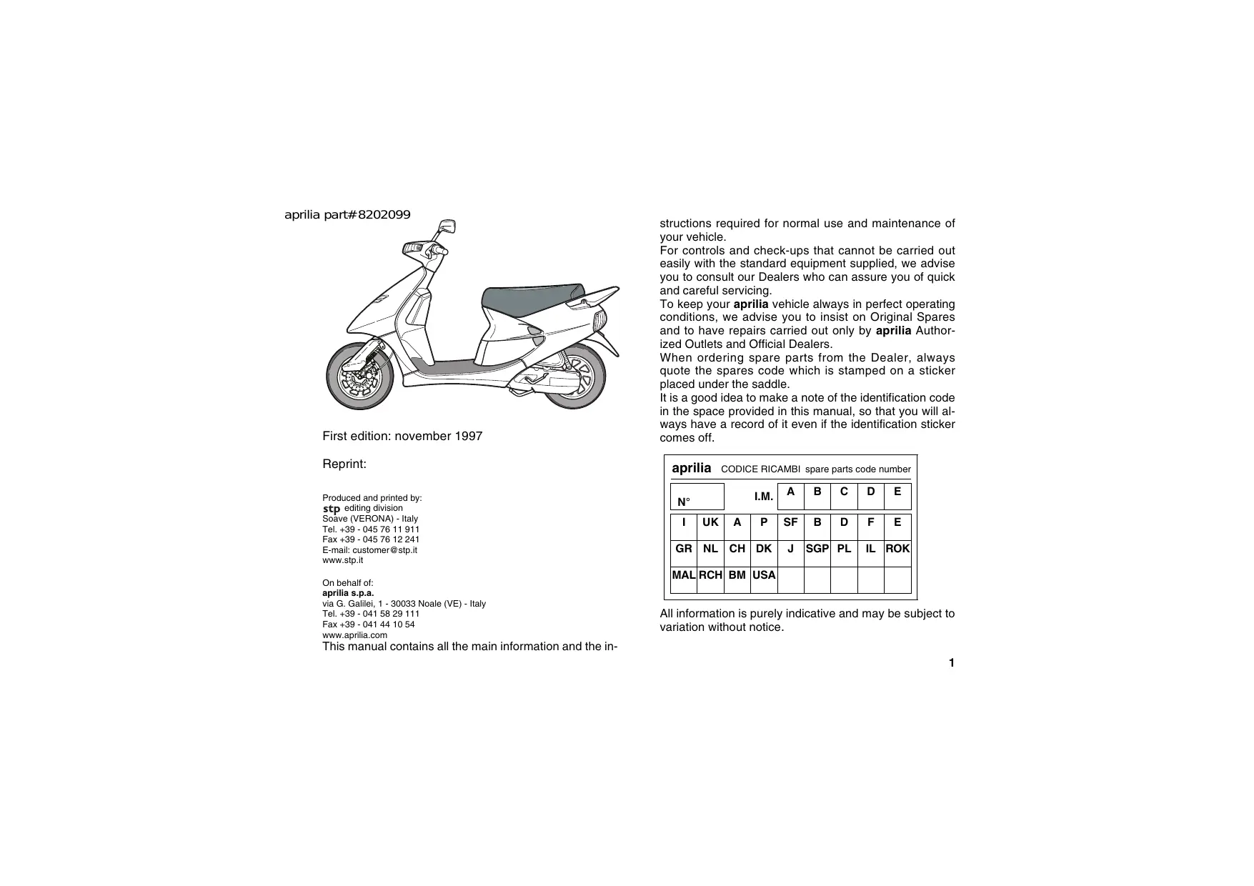
First edition: november 1997
Reprint:
Produced and printed by:
stp editing division
Soave (VERONA) - Italy
Tel. +39 - 045 76 11 911
Fax +39-045 76 12 241
E-mail: customer@stp.it
www.stp.it
On behalf of:
aprilia.s.p.a.
via G. Galilei, 1 - 30033 Noale (VE) - Italy
Tel. +39 - 041 58 29 111
Fax +39-041 44 10 54
www.aprilia.com
This manual contains all the main information and the in
structions required for normal use and maintenance of your vehicle.
For controls and check-ups that cannot be carried out easily with the standard equipment supplied, we advise you to consult our Dealers who can assure you of quick and careful servicing.
To keep your aprilia vehicle always in perfect operating conditions, we advise you to insist on Original Spares and to have repairs carried out only by aprilia Authorized Outlets and Official Dealers.
When ordering spare parts from the Dealer, always quote the spares code which is stamped on a sticker placed under the saddle.
It is a good idea to make a note of the identification code in the space provided in this manual, so that you will always have a record of it even if the identification sticker comes off.
| aprilia CODICE RICAMBI spare parts code number | ||||||||
| N° | I.M. | A | B | C | D | E | ||
| I | UK | A | P | SF | B | D | F | E |
| GR | NL | CH | DK | J | SGP | PL | IL | ROK |
| MAL | RCH | BM | USA | |||||
All information is purely indicative and may be subject to variation without notice.
Carefully observe the instructions preceded by the following warning signs:

Safety norms and regulations to protect the driver and other people from severe injuries or grave risks.

Indications to make the operations easier. Technical information.
In this manual the various versions are indicated by the following symbols:

catalytic version

Italy version

United Kingdom version

Austria version

Portugal version

Finland version

Belgium version

Germany version

France version

Spain version

Greece version

Holland version

Switzerland version

Denmark version

Japan version

Singapore version

Poland version

Israel version

South Korea version

Malaysia version

Chile version

Bermuda version

United States of America version
CONTENTS
page
Catalitic silencer 2
Technical data 3
Identification data 5
Controls arrangement. 6
Instructions for use 9
Maintenance instructions 15
Periodic maintenance chart 26
Lubricant chart 27
Wiring diagram 28
CATALYTIC SILENCER

Avoid parking the vehicle catalytic versions in near dry brush wood or in places easily accessible to children, as the catalytic silencer uses extremely hot during use; be very careful to avoid any kind of contact before it has completely cooled down.
The catalytic Amico 50 is fitted with a silencer with metal catalytic converter of the "platinum-rhodium bivalent" type. This device provides for the oxidation of the CO (carbon monoxide) and of the HC (unburned hydrocarbons) contained in the exhaust gases, changing them into carbon dioxide and steam, respectively.
Due to the catalytic reaction, the high temperature reached by the exhaust gases makes for the burning of the oil particles, thus keeping the silencer clean and eliminating the exhaust fumes.
To have the catalytic converter function correctly and for long and to reduce possible problems regarding the soiling of the thermal unit and of the exhaust, it is necessary to avoid covering long distances with the engine running at constantly low rpm.
It is sufficient to alternate these periods with periods in which the engine runs at relatively high rpm, even if only for a few seconds, but rather frequently.
What has been stated above assumes particular importance for the cold starting of the engine: in this case, in order to reach a rpm regime sufficient to enable the "priming" of the catalytic reaction, just make sure that the temperature of the thermal unit has reached at least 50^ , which generally occurs a few seconds after starting the engine.

Do not use leaded petrol, since it causes the destruction of the catalytic converter.
TECHNICAL DATA
MOTOR
Model . aprilia
Type 2-stroke single-cylinder with lamellar inlet
Cylinder cast iron
Bore / stroke 40 mm e 39,2 mm
Compression ratio 13:1
Displacement 49 cm3
Starting electric
Gearbox automatic converter with belt drive
Transmission oil capacity. 110 cm³
TRANSMISSION
Primary "V" belt
Secondary reduction gear
3YJ
IGNITION
Typ . electronic
Spark advance 14° at 5000 rpm 1,4 mm
before T.D.C.
Spark plug . NGK BR7 HS
CARBURETTOR
Model Dell'Orto PHBN 12 (TEI KEI TK12Y12)
FUEL SUPPLY
Fuel . premium grade petrol (4 Stars UK)
according to the DIN 51 600
standard, min. O.N. 98 (N.O.R.M.)
and 88 (N.O.M.M.)
Fuel unleaded petrol according
to the DIN 51 607 standard,
min. O.N. 95 (N.O.R.M.)
and 85 (N.O.M.M.)
Fuel tank capacity 7,5
of wich 2 reserve
Mixer oil tank capacity 1,3
FRAME
Type split single beam tubular steel frame
SUSPENSIONS
Front fork with articulated rod
Rear hydraulic monoshock absorber
BRAKES
Front disc 0155 mm
with hydraulic control
Rear .shoe brake 0110x25 mm
with mechanical control
TYRES
- Front 100/90×10"
Inflation pressure 170 kPa (1,7 bar)
Rear 100/90x10
Inflation pressure 190 kPa (1,9 bar)
with passenger. 210 kPa (2,1 bar)
RIMS
Front 2,50x10" light alloy
Rear 2,50×10" light alloy
ELECTRIC SYSTEM
Front lights 12V 15W
Front lights CH 12V 35/35W
Front parking light
(not provided in the NL versions) 12V 3 W
Rear light/stop light 12V 5/21 W
Turn indicators 12V 10W
Dash board light 5x12V 2W (warning lights);
Light for tool case/helmet case 12V 1,2W
Battery 12V 4Ah
Fuse. 7,5A
DIMENSIONS
Length 1780 mm
Width 690 mm (handle bar)
Height 1060 mm (handle bar); 760 mm (seat)
Centre to centre distance 1240 mm
Weight without fuel and oil 71 kg
IDENTIFICATION DATA
It is a good rule to write down the frame and engine numbers in the space provided in this manual.

Do not alter the identification numbers if you
do not want to incur severe penal and ad
ministrative sanctions.
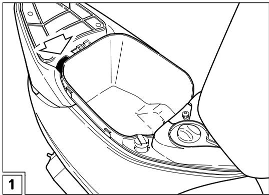
FRAME NUMBER (Fig. 1)
The frame number is stamped on the frame. To be able to read it, it is necessary to raise the saddle (1).
Frame no.
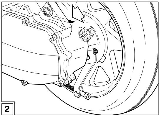
ENGINE NUMBER (Fig. 2)
The engine number is stamped on the lower support of the rear shock absorber.
Engine no.
CONTROLS ARRANGEMENT
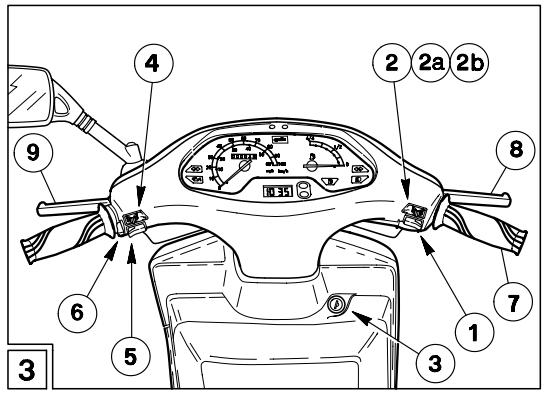
Fig. 3
1-Startpushbutton(3)
2-Lights switch ( D - 0E - )
2a-Lights switch (D-·)NL
2b - Lights switch (D - D - •) CH
3 - Ignition block/steering lock switch (○-×-×)
4 - Turn indicators switch (←→)
5 - Horn push button (
6 - Cold start lever (1-1)
7-Thraottle grip
8 - Front brake lever
9 - Rear brake lever
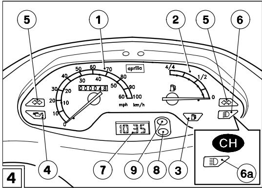
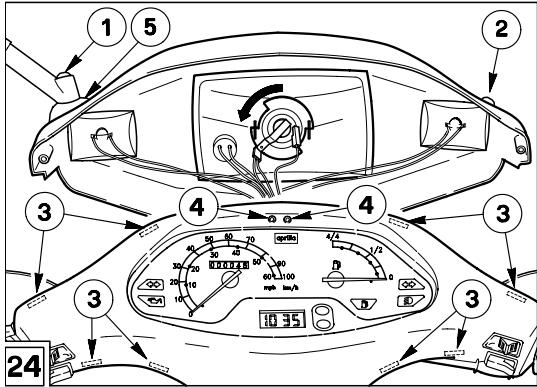
Fig. 4
1 - Speedometer / Odometer
2 - Fuel level indicator (R)
3 - Fuel reserve warning light (R)
4 - Mixer oil reserve warning light (
5 - Turn indicators warning light (↔ ⇌)
6 - Low beam warning light (D)
6a - High beam warning light (E0) CH
7 - Digital clock
8/9 - Clock adjustment and functions selection push buttons

Remember: 1 mile = 1.6 km
1 km = 0.625 miles
SETTING THE CLOCK (7-8-9-Fig. 4)
Display:
Normal display: hours and minutes.
Date display: press (9) once to display the month and date.
Seconds display: press (9) twice to display the seconds.
Setting
Press (8) once, the date and time will be displayed alternately.
- Month: press (8) again and the month will appear on the right (the rest disappears), press (9) to obtain the desired month.
Date: press (8) again and the date will appear on the right. Press (9) to obtain the desired date.
Hours: press (8) again and the hour will appear on the left with the letter "A" or "P" ("A" = a.m., "P" = p.m.). Press (9) to obtain the desired hour.
Minutes: press (8) again and the minutes will appear on the right of the display. Press (9) to obtain the desired minutes
The clock is now set. Press (8) again to return to normal operation.
CHANGING THE CLOCK CELL
Remove the front grille and headlamp unit, see pag. 25).
Remove the clock support from the rear of dashboard, acting on the snapcouplings.
Extract the clock and change the cell.
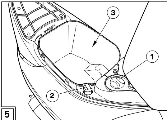
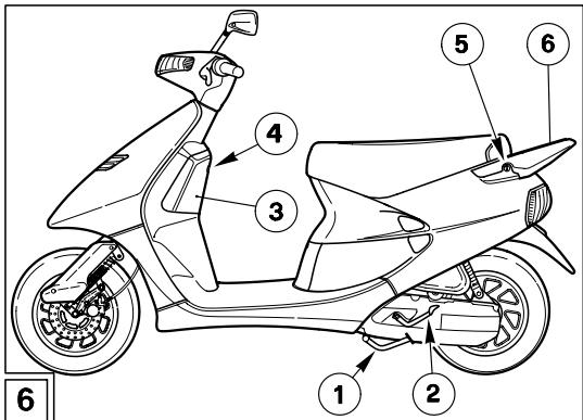
Fig. 5
1-Fuel tank plug
2 - Mixer oil tank plug
3 - Tool case/helmet case
Fig. 6
1 - Central stand
2 - Starter pedal
3 - Case
4 - Case lock
5 - Seat lock
6 - Carrier/handle
LOCKS
The key provided starts the engine, operates the steering lock (3-Fig. 3), the luggage case lock (4-Fig. 6) and the saddle lock (5-Fig. 6).

To operate the steering lock, turn the handlebars to the left, press the key, pull it up in it to "0" position, then extract the key.
INSTRUCTIONS FOR USE
STARTING

Exhaust gases contain carbon monoxide, which is extremely noxious if inhaled.
Avoid starting the vehicle in closed or badly
ventilated rooms.
The non-observance of this warning may cause loss of consciousness or even lead to death by asphyxia. Do not get on the vehicle for the starting.
Electric starting
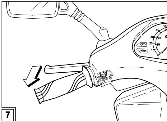
Position the vehicle on the stand.
Lock at least one wheel, by pulling a brake lever (Fig. 7). If this operation is not carried out, the start relay receives no current and therefore the engine does not start.
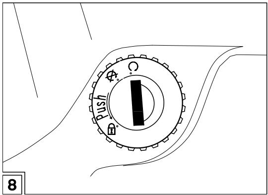
Turn the ignition switch (Fig. 8) to position "O".
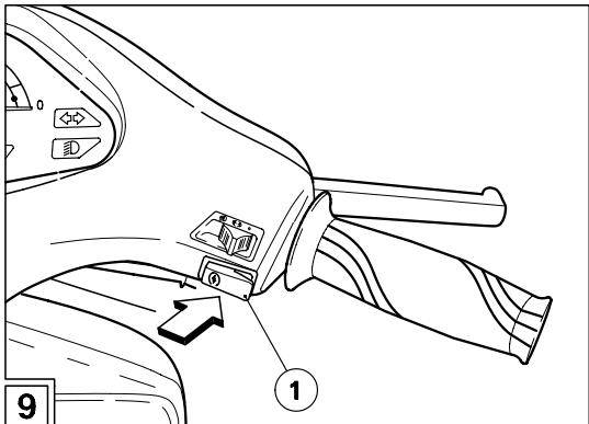
Press the start push button " ( 三 ) " 1-Fig.9 without accelerating, then release it as soon as the engine starts.

Avoid pressing the start push button "③" (3) when the engine is running: this may damage the starter.
When the start push button "③" is pressed, the 2 stroke oil reserve warning light "~~" comes on.
With the engine in running condition, when the start push button "③" is released, the 2 stroke oil reserve warning light "∑" must go out; if this does not occur, top up the 2 stroke oil tank.
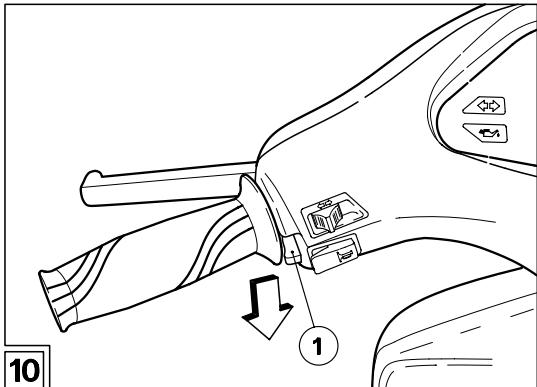
If the starting is carried out with cold engine, rotate the cold start lever "||" (1-Fig. 10) downwards.
Do not accelerate and pull the brake levers at the same time until you move off.
Warm the engine up before leaving.
- Once the engine has warmed up, rotate the cold start lever "| × " (1-Fig. 10) upwards.
KICK START
For the kick start, proceed as follows:
Position the vehicle on the centre stand.
Move to the left side of the vehicle.
To avoid losing control of the vehicle during the starting, lock both wheels by putting on the brake levers (Fig. 7).
Turn the ignition switch (Fig. 8) to position "O".

Do not push down the kick starter with the engine on.
Push down the kick starter with your right foot, releasing it immediately. If necessary, repeat the operation until the engine starts.
STARTING AFTER A LONG PERIOD OF INACTIVITY
After a long period of inactivity, proceed as follows:
Move the ignition switch (Fig. 8) to position "O".
Make the starter run for about 10 seconds, in order to ensure the filling up of the float chamber.
To start the engine:
Rotate the cold start lever "||" (1-Fig. 10) downwards.
Slightly open the throttle, then carry out the electric starting procedure (or KICK START).
DEPARTURE AND DRIVE
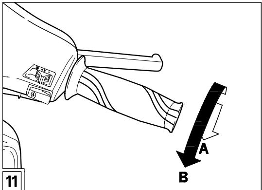
Release the throttle grip (Pos. A - Fig. 11), put on the rear brake, then move the vehicle down the stand. Get on the vehicle, keeping at least one foot on the ground in order not to lose balance.

Properly adjust the inclination of the rearview mirrors.
To leave, release the brake lever and accelerate by gently rotating the throttle grip (Pos. B - Fig. 11); the vehicle will start moving.

Avoid opening and closing the throttle grip repeatedly and continuously, so that you do not accidentally lose control of the vehicle.
If you have to brake, close the throttle and put on both brakes in order to obtain uniform deceleration, properly exerting pressure on the braking parts.
By putting on the front brake only or the rear brake only, you reduce the braking force considerably, thus running the risk of locking one wheel and consequently losing grip.
Before beginning to turn, slow down or brake driving at moderate and constant speed or accelerating slightly; avoid braking at the last moment: it would be very easy to skid.

If the brakes are operated continuously on downhill stretches, the friction surfaces can overheat, thus reducing the braking efficien
cy. Never drive with the engine off!
In case of wet ground or scarce wheel grip (snow, ice, mud, etc.), drive slowly, avoiding sudden brakings or manoeuvres that could make you lose grip and fall down.
Pay the utmost attention to any obstacle or variation of the ground.
Uneven roads, rails, manhole covers, indications painted on the road surface, building site metal plates become rather slippery by rain. For this reason all these obstacles have to be carefully avoided, driving smoothly and bending the vehicle as little as possible.
Always use the turn indicators timely when you intend to change lane or direction, avoiding sharp and dangerous movements.
RUNNING-IN

After the first 500 kilometres, carry out the checking operations indicated in the column "After running-in" of the PERIODIC MAINTE
NANCE CHART, see p. 26, in order to avoid hurting yourself or other people and/or damaging the vehicle.
The running-in of the engine is primary to ensure its correct functioning and its correct functioning.
If possible, drive on hilly roads and/or roads with many bends, so that the engine, the suspensions and the brakes undergo a more effective running-in.
For the first 500km , keep to the following indications:
0-300 km
Do not keep the throttle grip open more than one half for long stretches.
300-500 km
Do not keep the throttle grip open more than three-fourths for long stretches.

Remember: 1 mile = 1.6 km
1 km = 0.625 miles
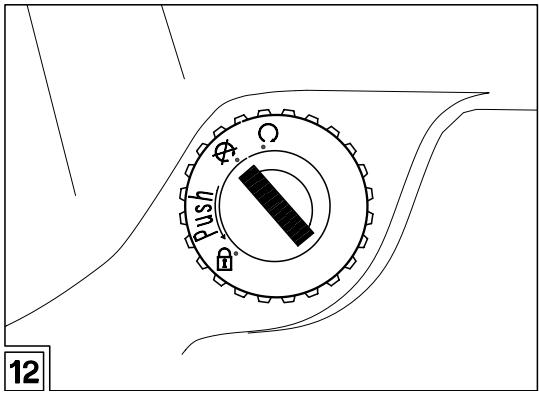
STOPPING AND PARKING (Fig. 12)
Release the throttle grip and stop the vehicle by putting on the brakes.
Move the ignition switch to position "X".
It is not necessary to close the fuel tap when the engine is off, since it is equipped with an automatic closing system.
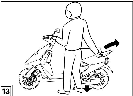
POSITIONING THE VEHICLE ON THE STAND (Fig. 13)
Park the vehicle on firm and flat ground, to prevent it from falling down.
Neither lean the vehicle against walls, nor lay it on the ground.
Make sure that the vehicle and especially its red-hot parts do not represent a danger for persons and children.
Do not leave the vehicle unattended when the engine is on or the key is inserted into the ignition switch.
Do not sit on the vehicle when the stand is down.
Seize the vehicle using the rear grab rail and at the same time push the stand lever downwards (see figure).
Make sure that the vehicle is resting firmly.
MAINTENANCE INSTRUCTIONS
FRONT BRAKE (Fig. 14)
This vehicle is provided with front hydraulic disc brake. When the disc pads wear out, the level of the fluid decreases to automatically compensate for their wear. Periodically check the brake fluid level in the tank and the wear of the pads, see p. 18 (CHECKING THE PAD WEAR).
REAR DRUM BRAKE

The brakes are the parts that most ensure your safety and for this reason they must always be perfectly working.
ADJUSTING THE BRAKE
Measure the distance covered by the lever (9-Fig. 3) before the brake starts it braking action.
The idle stroke at the end of the brake lever must be about 5 ÷ 10 ~mm .
Adjust the clearance by acting on the adjuster (1-Fig. 15).
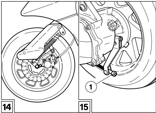
Put on the brake (9-Fig. 3) repeatedly and make sure that the wheel turns freely after the brake has been released.
Check the braking efficiency.

For any doubt regarding the perfect functioning of the braking system and in case you are not able to carry out the usual driving operations, contact your aprilia Official
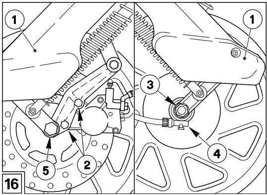
DISMANTLING THE FRONT WHEEL
(Fig. 16)
Remove the two plastic elements (1) protecting the stem.
Unscrew the two screws (2) and remove the brake caliper.
Unscrew the nut (3).
Upon reassembly position the odometer cable (4) correctly.
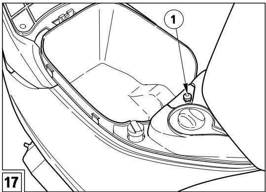
ADJUSTING THE ACCELERATION GRIP
(Fig. 17)
Adjust the play on the accelerator via the appropriate tightener on the carburettor.
To access the carburattor:
Remove the screw (1).
Pull the tool-helmet, compartment after disconnecting the compa-ment lighting cable.
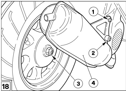
REMOVING THE REAR WHEEL (Fig. 18)

Before carrying out the following operations, let the engine and the silencer cool down until they reach room temperature, in
order to avoid burns.
Position the vehicle on the centre stand.
Unscrew and remove the two screws (1) and (2).
- Slacken the two screws that hold the exhaust silencer to the cylinder (access through the battery compartment)
Remove the silencer (4).

Upon reassembly, change the exhaust manifold-silencer seal.
Put on the rear brake (9 - Fig. 3) to lock the wheel.
Unscrew and remove the wheel nut (3) and the washer.

Upon reassembly, change the wheel nut (special type).
Wheel nut driving torque: 110 Nm (11 kgm).
Withdraw the wheel.
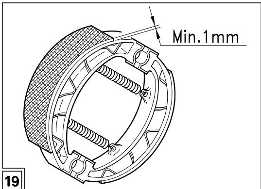
CHECKING THE SHOE WEAR (Fig. 19)
Check the wear of the rear brake shoes after the first 500km and successively every 4000km .

Remember: 1 mile = 1.6 km
1 km = 0.625 miles
To check the wear of the rear brake shoes, proceed as follows:
Remove the rear wheel, see p. 17 (REMOVING THE REAR WHEEL).
To check the thickness of the friction material, which must never be less than 1 mm (Fig. 19).
If the minimum allowed limit has been reached, if you notice any irregularity in the operation or if any part is damaged, contact your aprilia Official Dealer, who will provide for changing the brake shoes.
Check the brake pad wear after the first 500 km and successively every 2000 km.

Remember: 1 mile = 1.6 km
1 km = 0.625 miles
The wear of the brake pads depends on the use, on the kind of drive and on the road. The wear will be greater when the vehicle is driven on dirty or wet roads.
To carry out a rapid checking of the wear of the front pads, proceed as follows:
Position the vehicle on the centre stand.
Remove the brake caliper cover.
Carry out a visual checking of the friction material thickness by looking between the brake caliper and the pads.
If the thickness of the friction material (even of one pad only) has reduced to about 1 mm, replace both pads.

Have the pads changed by your aprilia Official Dealer.
GREASING THE REAR BRAKE CAM PIN (Fig. 20)

Grease the rear brake cam pin every 4000 km. If the vehicle is used on dusty roads, operation must be carried out more frequently.

Remember: 1 mile = 1.6 km
1 km = 0.625 miles
Disassemble the rear wheel, see p. 17 (REMOVING THE REAR WHEEL (Fig. 18)).
Unscrew and remove the adjuster (1-Fig. 15).

Do not dirt the shoes and the friction material with grease, to avoid compromising the braking efficiency of the vehicle.

This operation may be difficult because the springs resist considerably to the removal of the shoes. Be careful not to crush on your hands and fingers.
Grasp the inner edge of the two friction elements (1) at its centre and, pulling toward yourself, shake the two shoes, thus releasing them.
Loosen the nut (2) and remove the pin lever (3).
Withdraw the cam pin (4).

Moderately grease only the central part of the pin.
Avoid dirting the cam or the areas around
the pin seat with grease.
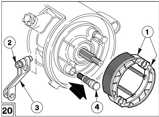
Grease the central part of the pin by using grease for kinematic motions, see p. 27 (LUBRICANT CHART).
Upon reassembly:

Neither strike, nor force the cam pin (4) with hammers or others tools, in order not to damage the two O-rings.
- Manually insert the cam pin (4), rotating and pushing it slightly.

Make sure that the springs are correctly coupled.
REMOVING AND CLEANING THE AIR FILTER

Remember: 1 mile = 1.6 km
1 km = 0.625 miles
Check the conditions of the air cleaner and clean it monthly or every 4000km depending on the conditions in which the vehicle is used.
If the vehicle is used on dusty or wet roads, the cleaning operations and any replacement should be carried out more frequently.
Position the vehicle on the stand.
To remove the left side panel of the vehicle.
Unscrew the four screws.
Remove the filter case cover and extract the filtering element.
To clean the filtering element use clean, non-inflammable solvents or solvents with high volatility point, then let it dry thoroughly.
Apply a filter oil or a thick oil (SAE 80W-90) on the whole surface of the filtering element, then squeeze it to eliminate the oil in excess.

The filter must be well impregnated, though not dripping.
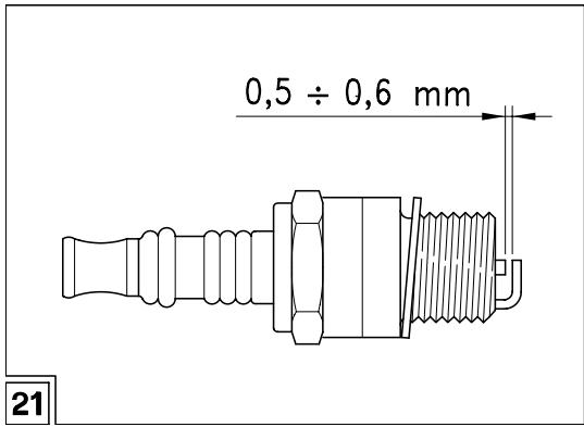
SPARK PLUG (Fig. 21)
Periodically remove the spark plug and clean it carefully, removing carbon deposits; change it if necessary.
To remove and clean the spark plug:
Remove the engine compartment cover.
Take off the spark plug cap.
Remove all the dirt from the base of the spark plug, then unscrew it with the spanner you will find in the tool kit and extract it from its seat, taking care that neither dust nor other substances enter the cylinder.
- Make sure that there are neither carbon deposits, nor corrosion marks on the electrode and on the central porcelain part; if necessary, clean them with the special cleaners for spark plugs, with an iron wire and/ or a metal brush.
- Energetically blow some air, in order to prevent the removed residues from getting into the engine. If the spark plug has crackings on the insulating material, corroded electrodes or excessive deposits, it must be changed.
- Check the spark plug gap with a thickness gauge. The gap must be 0,5 ÷ 0,6 ~mm ; if necessary adjust it, carefully bending the earth electrode.
Make sure that the washer is in good conditions.
With the washer on, screw the spark plug by hand in order not to damage the thread.
Tighten the spark plug by means of the spanner you will find in the tool kit, giving it half a turn to compress the washer.
Position the spark plug cap.
Put back the engine compartment cover.

The spark plug must be well tightened, otherwise the engine may overheat and be seriously damaged.
Change the spark plug every 8000km
Use the recommended type of spark plug only, see p. 3 (TECHNICAL DATA), in order not to compromise the life and performance of the engine.
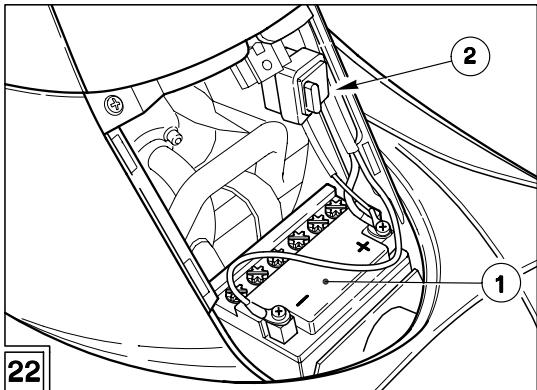
BATTERY (Fig. 22)

Remember: 1 mile = 1.6 km
1 km = 0.625 miles
Check the electrolyte level and the tightening of the terminals after the first 500km and successively every 4000 km or 8 months.

The electrolyte in the battery is toxic and caustic and if it gets in contact with the skin it can cause burns, since it contains sulphu
ric acid.
Wear protection clothes, a face mask and/or goggles during maintenance operations.
In case of contact with the skin, rinse with plenty of water.
In case of contact with the eyes, rinse with plenty of water for 15 minutes, then consult an oculist without delay.
If the electrolyte is accidentally swallowed, drink a lot of water or milk, then continue drinking milk of magnesia or vegetable oil and consult a doctor without delay.
The battery gives off explosive gases; keep it away from flames, sparks, cigarettes and any other source of heat.
During the recharging or the use, make sure that the room is properly ventilated and avoid inhaling the gases released during the recharging.

Never invert the connection of the battery cables.
to avoid dangerous leaks of the battery fluid.
KEEP AWAY FROM CHILDREN

Connect and disconnect the battery with the ignition switch in position "X".
the negative cable (-) .
Connect first the positive cable (+) and then.
ative cable (-)
Disconnect following the reverse order.
To check the battery (1), remove the engine compartment cover.
Make sure that the fluid level is included between the two "MIN" and "MAX" notches stamped on the battery side.
If necessary, top up by adding distilled water.
To recharge, disconnect the cables, extract the battery from its container and remove the element plugs.
A recharge with an amperage equal to 1/10th of the battery capacity is recommended.
After the recharging operation, check the electrolyte level again and if necessary top up with distilled water.
Tighten the element plugs.

Always connect the battery breather pipe, to prevent the sulphuric acid vapours from corroding the electric system, painted parts,
rubber elements or gaskets when they exit the breather pipe itself.
LONG INACTIVITY OF THE BATTERY
If the vehicle remains unused for a long period, remove the battery and place it in a cool and dry place.
Recharge it completely, by using a trickle charge.
If the battery remains on the vehicle, disconnect the cables from the terminals.
It is important to check the charge periodically (about once a month), during the winter or when the vehicle remains unused, in order to prevent the deterioration of the battery.
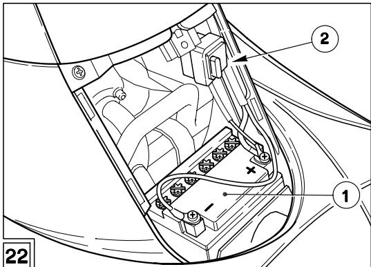
CHANGING THE FUSE (Fig. 22)

Do not repair faulty fuses.
Never use fuses different from the recommended ones.
The use of unsuitable fuses may cause damages to the electric system or, in case of short circuit, even a fire.
If an electric component fails to work, the fuse must be checked (2).
In this case it must be changed with another with the same amp value.
If the fuse cuts out again there is probably a short circuit in the electric system and it is advisable to consult an aprilia Official dealer.
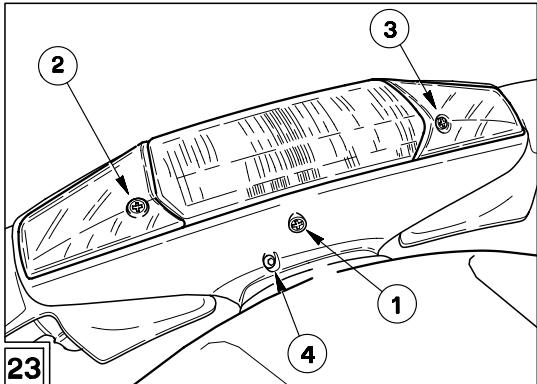
ADJUSTING THE HEADLAMP BEAM (Fig. 23)
The headlamp beam may be adjusted by turning the screw provided with a screwdriver (1).
CHANGING THE BULBS IN THE HEAD-LAMP AND FRONT DIRECTION INDICATORS (Fig. 23-24)
By slackening the two screws (2-3-Fig. 23) the two side covers of the direction indicators may be removed and the headlamp reflector unit released.
Access is thus obtained to the two bulbs of the direction indicators.
The front grille and headlamp unit must be dismantled so as to change the headlamp bulbs.
Access to the bulbs may be gained from behind the reflectors.
To remove them unscrew the 2 central screws (4-Fig. 24) the 2 screws at the side (1-2-Fig. 24), the screw at the front (4-Fig. 23) and release the 8 clips (3-Fig. 24).

Proceed with care.
Do not damage the tangs and/or their seats.
Handle the painted components with care
and avoid scraping or damaging them.

Upon reassembly, correctly position the base (5) of the rear mirror.
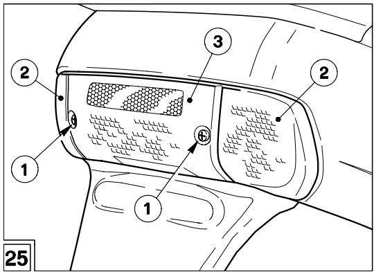
CHANGING THE BULBS IN THE REARLAMP AND REAR DIRECTION INDICATORS (Fig. 25)
Unscrew the two screws (1).
In this way the 3 transparent covers (2-3) are removed and the bulbs are accessible.
PERIODIC MAINTENANCE CHART
| Cheking operations | After running in 500 km | Every 4000 km | Every 8000 km | Notes |
| Clean and check spark plug | ★ | ★ | ||
| Clean air filter | ★ | |||
| Check and adjust idling | ★ | ★ | ||
| Check fuel pipes | ★ | |||
| Check drive oil level | change | ★ | change every 12000 km or 2 years | |
| Check the mixer oil | check every 500 km | |||
| Check op. mix pump and air bleeding | ★ | ★ | ||
| Check op. brakes and shoe wear | ★ | ★ | ||
| Greasing the rear brake cam pin | ★ | |||
| Checking the brake pad wear | ★ | every 2000 km | ||
| Brake liquid | periodically check | change every year | ||
| Check driving belt wear | ★ | |||
| Check wheel bearings | ★ | |||
| Check adjustment of steering bearings | ★ | ★ | ||
| Check battery electrolyte level | ★ | ★ | ||
| Check tyre wear | ★ | ★ | ||
| Check tyre pressure | every month | |||
| Check wheel alignment | ★ | |||
| Check tightness of nuts and bolts | ★ | ★ | ||
| Check rear shock absorber | ★ | |||
| Checking moving parts on front suspension | ★ | |||
| Cleaning scale from exhaust terminal | ★ | |||
| If the conditions of use are particularly severe, more frequent maintenance is advised. | ||||
LUBRICANT CHART
Transmission oil (recommended): F.C., SAE 75W - 90.
As an alternative to the recommended oil, it is possible to use high-quality oils with characteristics in compliance with or superior to the A.P.I. GL4 specifications.
Mixer oil (recommended): GREEN HIT.
Use high-quality oils with characteristics in compliance with or superior to the ISO-L-ETC++, A.P.I. TC++ specifications.
Fork oil (recommended): F.A. 5W or F.A. 20W fork oil.
If you need an oil with intermediate characteristics in comparison with the two recommended products, these can be mixed as indicated below:
SAE 10W F.A. 5W 67% of the volume, + F.A. 20W 33% of the volume.
SAE 15W F.A. 5W 33% of the volume, + F.A. 20W 67% of the volume.
Bearings and other lubrication points (recommended): AUTOGREASE MP.
As an alternative to the recommended product, use high-quality grease for rolling bearings, working temperature range -30^ +140^ , dripping point 150^ 230^ , high protection against corrosion, good to water and oxidation resistance.
Protection of the battery poles: neutral grease or vaseline.
Spray grease for chains (recommended): CHAIN SPRAY.
Brake fluid (recommended): F.F., DOT 5 (DOT 4 compatible).

Use new brake fluid only.
Engine coolant (recommended): ECOBLU -40°C.

Use only antifreeze and anticorrosive without nitrite, ensuring protection at -35^ at least.
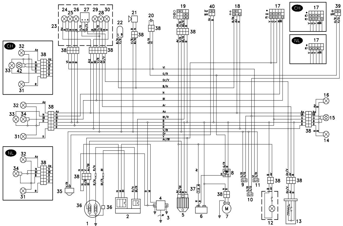
WIRING DIAGRAM KEY - AMICO 50
1) Generator
2) CDI
3) Spark plug
4) H.T. coil
5) Voltage regulator
6) Battery
7) Starter
8) Start relay
9) Front stoplight switch
10) Rear stoplight switch
11) Mixer oil reserve switch
13) Fuel level sensor
14) Right rear turn indicator
15) Rear light
16) Left rear turn indicator
17) Dip switch
18) Turn indicator switch
19) Ignition switch
20) Control diode
21) Crash helmet compartment light
22) Blinking
23) Dashboard
24) Turn indicator warning light
25) Mixer oil reserve warning light
26) Dashboard light
27) Fuel level indicator
28) Low fuel warning light
29) Low beam warning light
30) Crash helmet compartment light switch
31) Front right turn indicator
32) Front left turn indicator
33) Front parking light (not provided in the version)
34) Low beam
35) Horn
36) Pick up
37) Fuse
38) Multiple connectors
39) START push button
40) Horn push button
42) Low/High beam
CABLE COLOURS
Ar Orange
Az Light blue
B Blue
BI White
G Yellow
Gr Gray
M Brown
N Black
Red
V Green
Vi Violet
aprilia s.p.a. wishes to thank its customers for the purchase of this vehicle.
- Do not dispose of oil, fuel or polluting substances and components in the environment.
- Do not keep the engine running if it isn't necessary.
- Avoid troublesome noises.
- Respect nature.
- Reprint:
- CONTENTS
- CATALYTIC SILENCER
- Do not use leaded petrol, since it causes the destruction of the catalytic converter.
- TECHNICAL DATA
- MOTOR
- TRANSMISSION
- IGNITION
- CARBURETTOR
- FUEL SUPPLY
- FRAME
- SUSPENSIONS
- BRAKES
- TYRES
- RIMS
- ELECTRIC SYSTEM
- DIMENSIONS
- IDENTIFICATION DATA
- FRAME NUMBER (Fig. 1)
- ENGINE NUMBER (Fig. 2)
- CONTROLS ARRANGEMENT
- Fig. 3
- Fig. 4
- SETTING THE CLOCK (7-8-9-Fig. 4)
- Display:
- Setting
- CHANGING THE CLOCK CELL
- Fig. 5
- Fig. 6
- LOCKS
- INSTRUCTIONS FOR USE
- STARTING
- Electric starting
- KICK START
- Do not push down the kick starter with the engine on.
- STARTING AFTER A LONG PERIOD OF INACTIVITY
- DEPARTURE AND DRIVE
- RUNNING-IN
- 0-300 km
- 300-500 km
- STOPPING AND PARKING (Fig. 12)
- POSITIONING THE VEHICLE ON THE STAND (Fig. 13)
- MAINTENANCE INSTRUCTIONS
- FRONT BRAKE (Fig. 14)
- REAR DRUM BRAKE
- ADJUSTING THE BRAKE
- DISMANTLING THE FRONT WHEEL
- (Fig. 16)
- ADJUSTING THE ACCELERATION GRIP
- (Fig. 17)
- REMOVING THE REAR WHEEL (Fig. 18)
- CHECKING THE SHOE WEAR (Fig. 19)
- GREASING THE REAR BRAKE CAM PIN (Fig. 20)
- REMOVING AND CLEANING THE AIR FILTER
- SPARK PLUG (Fig. 21)
- BATTERY (Fig. 22)
- KEEP AWAY FROM CHILDREN
- LONG INACTIVITY OF THE BATTERY
- CHANGING THE FUSE (Fig. 22)
- ADJUSTING THE HEADLAMP BEAM (Fig. 23)
- CHANGING THE BULBS IN THE HEAD-LAMP AND FRONT DIRECTION INDICATORS (Fig. 23-24)
- CHANGING THE BULBS IN THE REARLAMP AND REAR DIRECTION INDICATORS (Fig. 25)
- LUBRICANT CHART
- WIRING DIAGRAM KEY - AMICO 50
- CABLE COLOURS
Brand : APRILIA
Model : AMICO 50
Category : Scooter