
AREA 51 - Scooter APRILIA - Free user manual and instructions
Find the device manual for free AREA 51 APRILIA in PDF.
| Product type | Scooter 50 cc, 2-stroke |
| Brand and model | APRILIA AREA 51 |
| Dimensions (L × W × H) | 1790 × 701.5 × 1110 mm |
| Seat height | 810 mm |
| Wheelbase | 1260 mm |
| Ground clearance | 140 mm |
| Dry weight | 106 kg |
| Engine | Single-cylinder 2-stroke, liquid cooling, 49.26 cc, bore 40 mm, stroke 39.2 mm, compression ratio 12.5:1 |
| Fuel | Premium unleaded gasoline 95 RON (min. 95 RON) or super 98 RON (min. 98 RON) |
| Fuel tank capacity | 11.5 L (reserve 2 ± 0.5 L) |
| 2-stroke oil | Tank 1.3 L (reserve 0.3 L), recommended GREEN HIT or equivalent ISO-L-ETC++, API TC++ |
| Transmission | Continuously variable automatic belt drive, centrifugal clutch |
| Brakes | Hydraulic disc front and rear, Ø 190 mm |
| Front suspension | Telescopic fork, travel 57 mm |
| Rear suspension | Hydraulic mono-shock, travel 90 mm |
| Tires | Front and rear: tubeless 130/60-13; solo pressure 1.8 bar (front) / 2.0 bar (rear), with passenger 2.0 bar (front) / 2.2 bar (rear) |
| Battery | 12 V – 4 Ah, with maintenance (electrolyte level) |
| Ignition | CDI, advance 14° ± 2° BTDC, spark plug NGK R BR8 HS (gap 0.5–0.6 mm) |
| Lighting | Low beam 12V–15W (×2), turn signals 12V–10W, tail/stop light 12V–5/21W |
| Routine maintenance | Transmission oil change every 3000 km, spark plug check every 4000 km, air filter replacement every 4000 km, coolant change every 2 years |
| Maximum load | Rider + luggage: 105 kg; with passenger (depending on country): 180 kg |
| Spare parts | Use only original APRILIA parts; available at authorized dealers |
| Manual and repairability | Complete 73-page manual; some operations require a qualified mechanic; wiring diagram provided |
Frequently Asked Questions - AREA 51 APRILIA
User questions about AREA 51 APRILIA
0 question about this device. Answer the ones you know or ask your own.
Ask a new question about this device
Download the instructions for your Scooter in PDF format for free! Find your manual AREA 51 - APRILIA and take your electronic device back in hand. On this page are published all the documents necessary for the use of your device. AREA 51 by APRILIA.
USER MANUAL AREA 51 APRILIA
This manual is to be considered an integral part of the vehicle, which must be delivered complete with it also in case of resale.
aprilia s.p.a. reserves the right to modify its models at any time, without prejudice to the main characteristics here described.
All rights as to electronic storage, reproduction and total or partial adaptation, with any means, are reserved for all Countries.
The mention to products or services supplied by third parties is made only for information purposes and is not binding in any case.
aprilia s.p.a takes no responsibility as to the performance or the use of said products.
First edition: may 1998
Reprint:
Produced and printed by:
Studio Tecno Public
Viale del Progresso - 37038 Soave (VR) - Italy
Tel. +39 (0)45 -76 11 911
Fax +39 (0)45 -76 12 241
www.stp.it
E-mail: customer@stp.it
On behalf of:
aprilia.s.p.a.
via G. Galilei, 1 - 30033 Noale (VE) - Italy
Tel. +39 (0)41 - 58 29 111
Fax +39 (0)41 - 44 10 54
www.aprilia.com
FOREWORD
Before starting the engine, carefully read this manual, paying particular attention to the chapter "RIDING SAFELY".
Your and other people's safety depends not only on your quickness of reflexes and on your agility, but also on what you know about the vehicle, on its efficiency and on your knowledge of the basic information for RIDING SAFELY.
Therefore, get a thorough knowledge of the vehicle, in such a way as to be able to drive in the traffic safely.
For the controls and repairs not expressly described in this manual, for the purchase of aprilia Genuine Spare Parts, accessories and other products, as well as for specific technical advice, contact only aprilia Authorized Outlets and Official Dealers, who can ensure you reliable and prompt servicing.
Thank you for choosing aprilia. We wish you a nice ride.
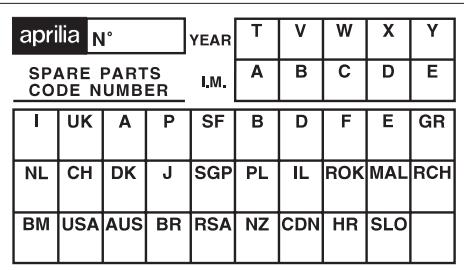
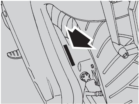
IMPORTANT:
When asking your Dealer for spare parts, specify the spare parts code indicated on the SPARE PARTS IDENTIFICATION LABEL. Write down the identification code in the space here below, in order to remember it also in case of loss or deterioration of the label.
The label is glued onto the right beam of the frame; to be able to read it, remove the front inspection cover, see p. 46 (REMOVING THE FRONT INSPECTION COVER).
Carefully observe the instructions preceded by the following warning signs:

Safety norms and regulations to protect the driver and other people from severe injuries or grave risks.

Indications to make the operations easier. Technical information.
The operations preceded by this symbol must be repeated on the opposite side of the vehicle.
In this manual the various versions are indicated by the following symbols:

automatic light switching version (Automatic Switch-on Device)

optional

catalytic version
VERSION:

Italy

Holland

Bermuda

United Kingdom

Switzerland

United States of America

Austria

Denmark

Australia

Portugal

Japan

Brazil

Finland

Singapore

South Africa

Belgium

Poland

New Zealand

Germany

Israel

Canada

France

South Korea

Hungary

Spain

Malaysia

Slovenia

Greece

Chile
TABLE OF CONTENTS
SAFE DRIVE 5
BASIC SAFETY RULES 6
CLOTHING 9
ACCESSIONS 10
LOAD 10
ARRANGEMENT OF THE MAIN ELEMENTS ..12
ARRANGEMENT OF THE INSTRUMENTS 14
INSTRUMENTS AND INDICATORS 14
INSTRUMENT AND INDICATOR TABLE ...15
PROGRAMMING PUSH BUTTONS 16
MAIN INDEPENDENT CONTROLS 18
PRELIMINARY CHECKING OPERATIONS 29
STARTING 30
DEPARTURE AND DRIVE 32
RUNNING-IN 33
STOPPING 33
PARKING 33
POSITIONING THE VEHICLE
ON THE STAND 34
SUGGESTIONS
TO PREVENT THEFT 34
MAINTENANCE 35
REGULAR SERVICE INTERVALS CHART .35
IDENTIFICATION DATA 36
AIR CLEANER 37
CHECKING
THE TRANSMISSION OIL LEVEL 38
CHANGING
THE TRANSMISSION OIL 39
FRONT WHEEL 40
REAR WHEEL 42
CHECKING THE BRAKE PAD WEAR 43
REMOVING THE FRONT AND REAR
BRAKE CALIPERS 43
CHECKING THE STEERING 44
CHECKING
THE ENGINE FULCRUM AXIS 44
REMOVING THE EXHAUST SILENCER ....45
REMOVING THE REAR-VIEW MIRROR ....45
REMOVING
THE FRONT INSPECTION COVER 46
REMOVING THE RIGHT
AND LEFT INSPECTION COVERS 46
REMOVING THE REAR
INSPECTION COVER 46
IDLING ADJUSTMENT 47
ADJUSTING
THE ACCELERATOR CONTROL 47
SPARK PLUG 48
BATTERY 49
LONG INACTIVITY
OF THE BATTERY 49
CHECKING AND CLEANING
THE TERMINALS 50
REMOVING THE BATTERY 50
CHECKING
THE ELECTROLYT ELEVEL 51
RECHARGING THE BATTERY 51
INSTALLING THE BATTERY 51
CHANGING THE FUSE 52
ADJUSTING
THE VERTICAL HEADLIGHT BEAM 53
BULBS 53
CHANGING THE HEADLIGHT BULBS 54
CHANGING
THE REAR LIGHT BULB 56
CHANGING THE NUMBER PLATE BULB
A CH IL ROK ASD 56
TRANSPORT 57
DRAINING THE FUEL TANK 57
CLEANING 58
LONG PERIODS OF INACTIVITY 59
AFTER A PERIOD OF INACTIVITY 59
TECHNICAL DATA 60
LUBRICANT CHART 64
Importers 66-67
WIRINGDIAGRAMArea51 68
WIRINGDIAGRAMKEYArea51 69
aprilia
safe drive

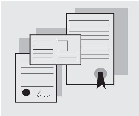

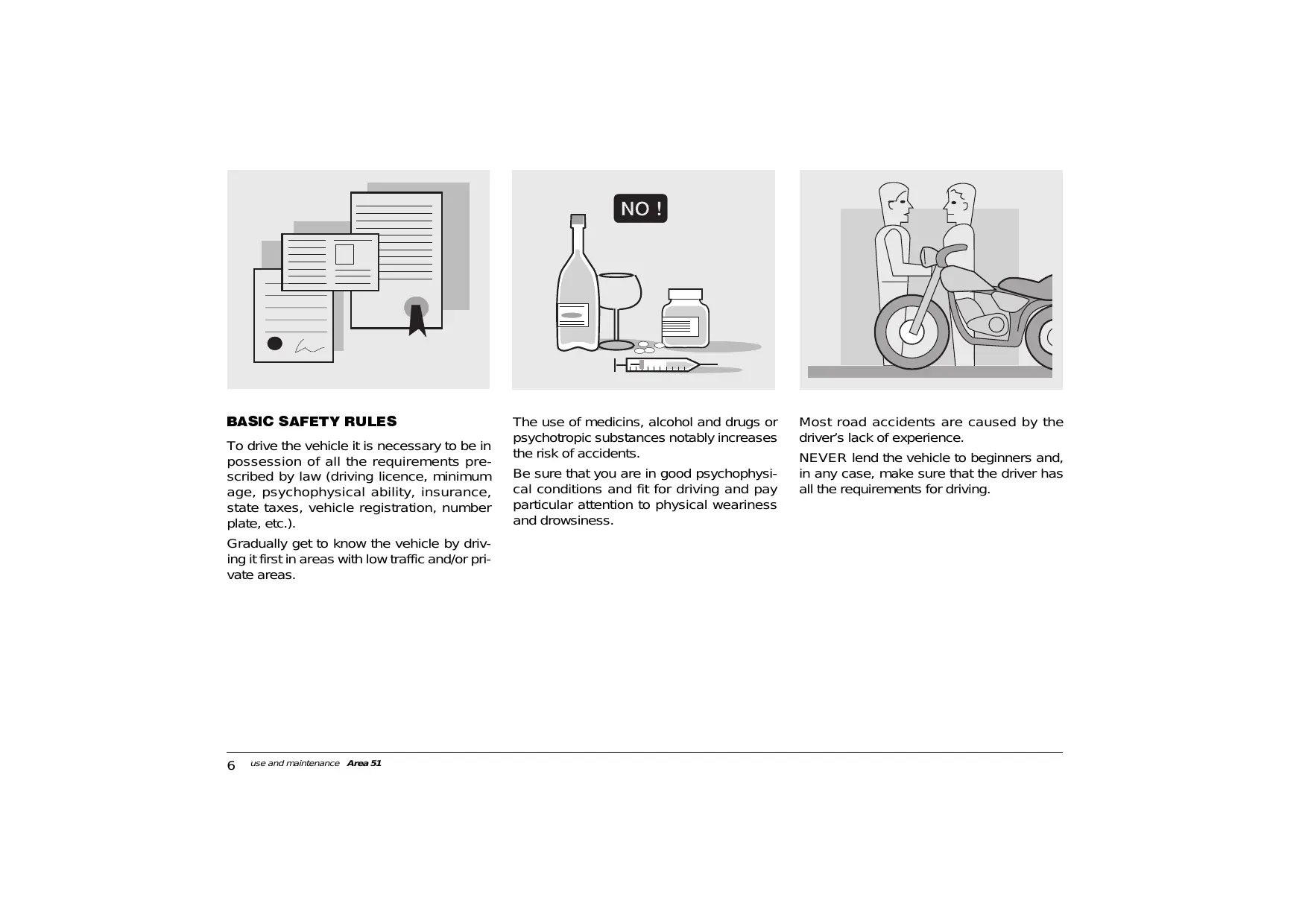
BASIC SAFETY RULES
To drive the vehicle it is necessary to be in possession of all the requirements prescribed by law (driving licence, minimum age, psychophysical ability, insurance, state taxes, vehicle registration, number plate, etc.).
Gradually get to know the vehicle by driving it first in areas with low traffic and/or private areas.
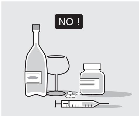
The use of medicines, alcohol and drugs or psychotropic substances notably increases the risk of accidents.
Be sure that you are in good psychophysical conditions and fit for driving and pay particular attention to physical weariness and drowsiness.
Most road accidents are caused by the driver's lack of experience.
NEVER lend the vehicle to beginners and, in any case, make sure that the driver has all the requirements for driving.
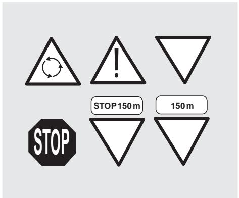
Rigorously observe all road signs and national and local road regulations.
Avoid abrupt movements that can be dangerous for yourself and other people (for example: rearing up on the back wheel, speeding, etc.), and give due consideration to the road surface, visibility and other driving conditions.
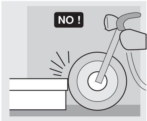
Avoid obstacles that could damage the vehicle or make you lose control.
Avoid riding in the slipstream created by preceding vehicles in order to increase your speed.
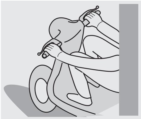
Always drive with both hands on the handlebars and both feet on the footrests, in the correct driving posture.
Avoid standing up or stretching your limbs while driving.
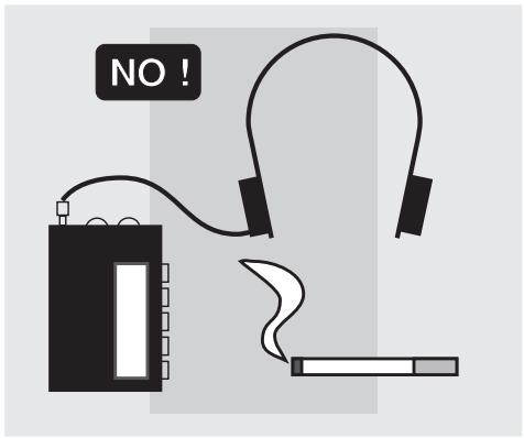
The driver should pay attention and avoid distractions caused by people, things and movements (never smoke, eat, drink, read, etc.) while driving.
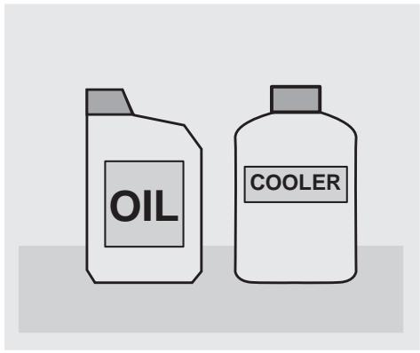
Use only the vehicle's specific fuels and lubricants (indicated in the "LUBRICANT CHART"); check all oil, fuel and coolant levels regularly.
If the vehicle has been involved in an accident, make sure that no damage has occurred to the control levers, pipes, wires, braking system and vital parts.
If necessary, have the vehicle inspected by an aprilia Official Dealer, who should carefully check the frame, handlebars, suspensions, safety parts and all the devices that you cannot check by yourself.
Always remember to report any malfunction to the technicians to help them in their work.
Never use the vehicle when the amount of damage it has suffered endangers your safety.
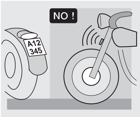
Never change the position, inclination or colour of: number plate, direction indicators, lights and horns.
Any modification of the vehicle will result in the invalidity of the guarantee.
Any modification of the engine or of other members which is aimed at increasing the speed or the power of the vehicle is prohibited by the law; in fact, any modification resulting in an increase of the maximum speed or of the engine displacement would change the scooter into a motorcycle, which implies the following obligations for the owner:
- new homologation;
- new registration;
- appropriate driving license.
Further, said modifications cause the loss of the insurance cover, since insurance policies expressly prohibit to make technical changes aimed at increasing the vehicle performance levels.
For the reasons stated above, the failure to comply with the tampering prohibition is punished by law with opposite sanctions (including the confiscation of the vehicle), which, according to the case, can be combined with the sanctions provided for not using the crash helmet and/or the number plate, for the violation of fiscal obligations (ownership tax) and with penal sanctions provided for using the vehicle without driving license.
Never race with other vehicles.
Avoid off-road driving.
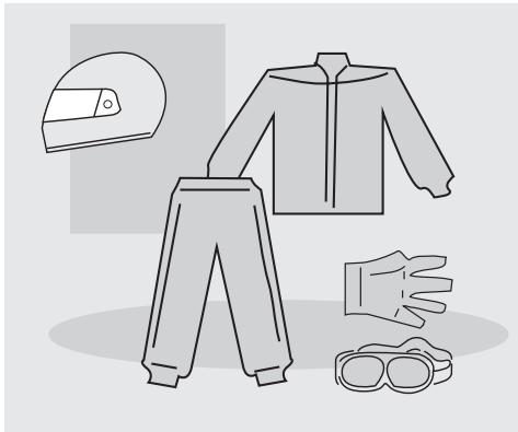
CLOTHING
Before starting, always wear a correctly fastened crash helmet. Make sure that it is homologated, in good shape, of the right size and that the visor is clean.
Wear protective clothing, preferably in light and/or reflecting colours. In this way you will make yourself more visible to the other drivers, thus notably reducing the risk of being knocked down, and you will be more protected in case of fall. This clothing should be very tight-fitting and fastened at the wrists and ankles. Strings, belts and ties should not be hanging loose; prevent these and other objects from interfering with driving by getting entangled with moving parts or driving mechanisms.
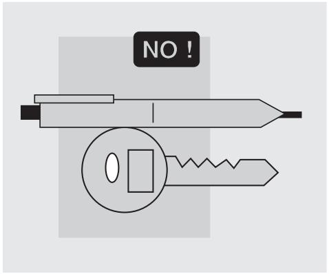
Do not keep objects that can be dangerous in case of fall, for example pointed objects like keys, pens, glass vials etc. in your pockets (the same recommendations also apply to passengers).
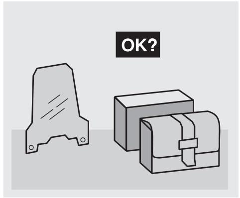
ACCESSORIES
The owner of the vehicle is responsible for the choice, installation and use of any accessory.
Avoid installing accessories that cover horns or lights or that could impair their functions, limit the suspension stroke and the steering angle, hamper the operation of the controls and reduce the distance from the ground and the angle of inclination in turns. Avoid using accessories that hamper access to the controls, since this can prolong reaction times during an emergency. Large fairings and windscreens assembled on the vehicle can produce aerodynamic forces capable of compromising the stability of the vehicle while driving. Make sure that the equipment is well fastened to the vehicle and not dangerous during driving.
Do not install electrical devices and do not modify those already existing to avoid electrical overloads, because the vehicle could suddenly stop or there could be a dangerous current shortage in the horn and in the lights. aprilia recommends the use of "aprilia genuine accessories".
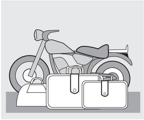
LOAD
Be careful and moderate when loading your luggage. Keep any luggage loaded as close as possible to the centre of the vehicle and distribute the load uniformly on both sides, in order to reduce imbalance to the minimum. Furthermore, make sure that the load is firmly secured to the vehicle, especially during long trips.
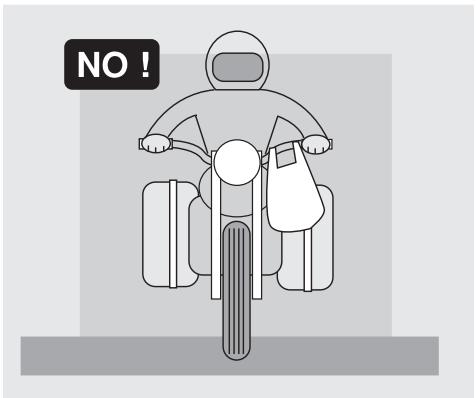

Avoid hanging bulky, heavy and/or dangerous objects on the handlebars, mudguards and forks, because the vehicle might respond more slowly in turns and its manoeuvrability could be unavoidably impaired.
Do not place bags that are too bulky on the vehicle sides, because it could hit people or obstacles making you lose control of the vehicle.
Do not carry any bag if it is not tightly secured to the vehicle.
Do not carry bags which protrude too much from the luggage-rack or which cover the lights, horn or indicators.
Do not carry animals or children on the glove compartment or on the luggage-rack.
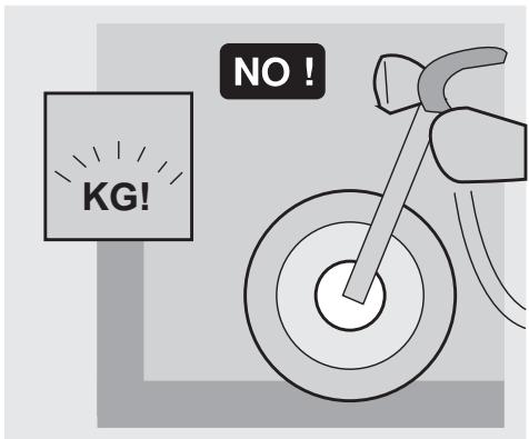
Do not exceed the maximum load allowed for each side-bag.
When the vehicle is overloaded, its stability and its manoeuvrability can be compromised.
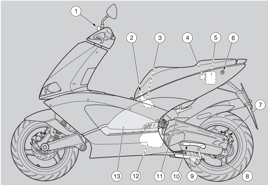
KEY
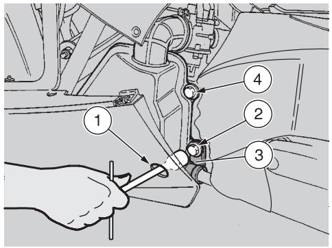
1) Brake fluid reservoir (rear brake)
2) Coolant expansion tank plug
3) Coolant expansion tank
4) Fuse carrier
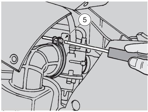
5) Battery
6) Saddle lock
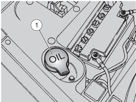
7) Transmission oil filling cap
8) Transmission oil drain plug
9) Centre stand
10) Kick starter
11) Passenger left footrest (snapping, closed/open) (in the countries where required)
12) Air cleaner
13) Left inspection cover

KEY
1) Rear inspection cover
2) Mixer oil tank plug
3) Mixer oil tank
4) Ignition switch/steering lock
5) Front inspection cover
6) Fuel tank plug
7) Brake fluid reservoir (front brake)
8) Horn
9) Fuel tank
10) Right inspection cover
11) Anti-theft hook (for the aprilia "Body-Guard" armored cable OPT)
12) Passenger right footrest (snapping, closed/open) (in the countries where required)
ARRANGEMENT OF THE INSTRUMENTS
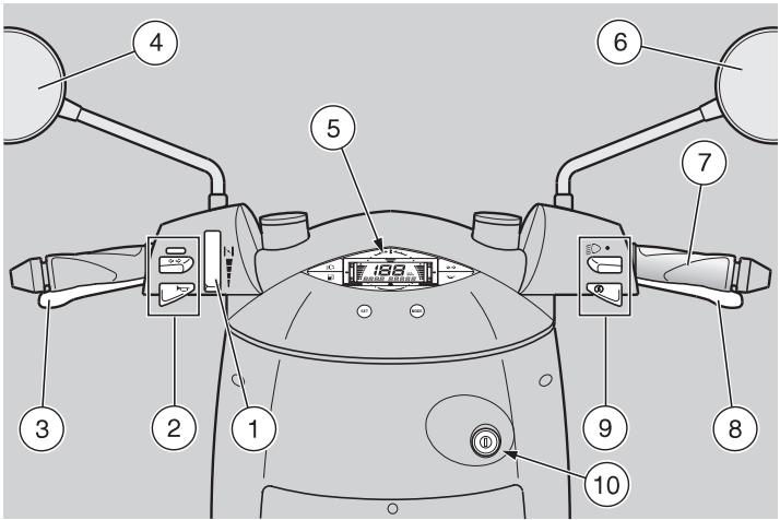
KEY
1) Cold start lever (▶)
2) Electric controls on the left side of the handlebar
3) Rear brake lever
4) Left rear-view mirror (not provided in the UK version)
5) Instruments and indicators
6) Right rear-view mirror (in the countries where required)
7) Throttle grip
8) Front brake lever
9) Electric controls on the right side of the handlebar
10) Ignition switch/steering lock ( - -)
INSTRUMENTS AND INDICATORS
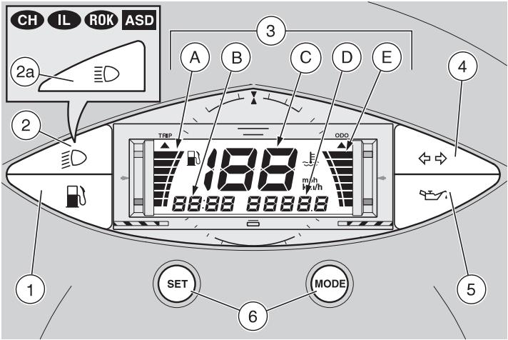
KEY
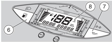
1) Amber low fuel warning light (B)
2) Green low beam warning light (D)
2a) Blue high beam warning light (E0) CH IL 80R ASD
3) Multifunction digital display:
A - Fuel level indicator (B) (indicator scale on the left)
B - Clock
C - Speedometer
D - Odometer (Mileage counter for the UK only)
E - Coolant temperature indicator (±) (indicator scale on the right
4) Green direction indicator warning light ( )
5) Red 2 stroke oil reserve warning light (
6) SET and MODE programming push buttons
INSTRUMENT AND INDICATOR TABLE
| Description | Function | |
| Direction indicator warning light ⇔ ⇔ | It blinks when the direction indicators are on. | |
| 2 stroke oil reserve warning light ⇔ ⇔ | It comes on when the ignition switch is in position “○”, thus checking the proper functioning of the LED. If the LED does not come on during the starting, contact an aprilia Authorized Dealer. If the warning light comes on and does not go out after the check, or if it comes on dur- ing normal functioning, this means that the 2-stroke oil reserve is being used; in this case, top up the 2-stroke oil tank, see p. 24 (2 STROKE OIL TANK). | |
| Low beam warning light ⇔ ⇔ | It comes on when the headlight is in low beam position. | |
| High beam warning light CH RL ROK ASD ⇔ ⇔ | It comes on when the headlight in high beam position. | |
| Low fuel warning light ⇔ ⇔ | It comes on when the quantity of fuel left in the tank is about 2±0,5 l. | |
| Multifunc-tion digital display | Fuel level indicator ⇔ ⇔ | It indicates the approximate fuel level in the tank. When the fuel tank is full, the indicator scale is completely lit up in correspondence with the gray refer-ence mark (on the left upper side). As the fuel level decreases, the lit area decreases as well; when it reaches the red mark (on the left lower side), the low fuel warning light “” comes on. |
| Coolant temperature indicator ⇔ ⇔ | It indicates the approximate temperature of the coolant in the engine. When the indicator scale starts to light up (light blue reference mark on the right lower side), the cool-ant temperature is sufficient to ensure the trouble-free running of the vehicle. If the lit area on the scale reaches the red mark (on the right upper side) and blinks, stop the engine and check the coolant level, see p. 26 (COOLANT). If the maximum allowed temperature is exceeded (indicator scale completely lit up), the engine may be seriously damaged. | |
| Speedometer | It indicates the instantaneous driving speed in kilometres (or miles for the UK only) according to the presetting, see p. 16 (PROGRAMMING PUSH BUTTONS). | |
| Odometer | It indicates the total or partial number of kilometres covered. | |
| Mileage counter (for the UK only) | It indicates the total or partial number of miles covered. | |
| Clock | It indicates the hour and minutes according to the presetting, see p. 16 (PROGRAMMING PUSH BUT-TONS). | |
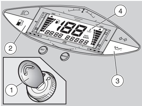
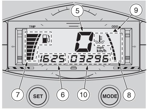
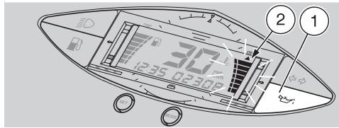
PROGRAMMING PUSH BUTTONS
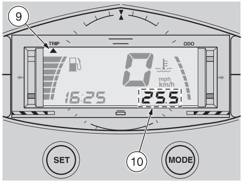
When the ignition key (1) is turned to position "O", the following lights come on simultaneously on the dashboard:
amber low fuel warning light (b) (2);
- red 2-stroke oil reserve warning light (3);
the entire display (4) for approximately three seconds, after which the speedometer (5) will indicate "0" and the following functions will remain on: the clock (6), the symbols corresponding to the fuel level indicator "1" (7) and to the coolant temperature indicator "2" (8), the arrow "▲" (9) under the writing ODO (or TRIP) and the segments (10) indicating the total (or partial) number of kilometres (miles for the UK only) covered.
The position of the arrow (9) under the writing ODO or TRIP depends on the last setting made, see be
low (SWITCHING FROM TOTAL KILOMETRES ODOMETER TO TRIP ODOMETER (TOTAL MILEAGE COUNTER / TRIP MILEAGE COUNTER FOR THE UK ONLY)).
SWITCHING FROM TOTAL KILOMETRES ODOMETER TO TRIP ODOMETER (TOTAL MILEAGE COUNTER / TRIP MILEAGE COUNTER FOR THE ☑ ONLY)
Press and release the MODE push button; the arrow "▲" (9) will move from under the writing ODO to under the writing TRIP (or viceversa), and at the same time the segments (10) will indicate the total or partial number of kilometres (miles for the UK only) covered.
ODO = total kilometres odometer (total mileage counter for the UK only).
TRIP = trip odometer (trip mileage counter for the UK only).

The arrow “▲” (9) will move every time the MODE push button is used and released.
The selected setting appears every time the vehicle is started.
To set the trip odometer (trip mileage counter for the UK only) to zero, proceed as follows:
Press and release the MODE push button, in such a way as to move the arrow "▲" (9) under the writing TRIP.
Press the SET push button for about three seconds and the segments (10) will be set to zero.
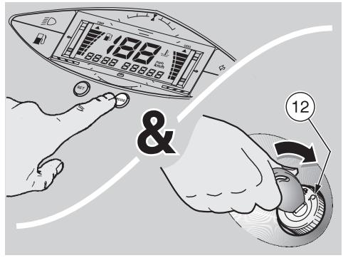
SWITCHING FROM KILOMETRES (km/h) TO MILES (MPH) FOR THE UK ONLY
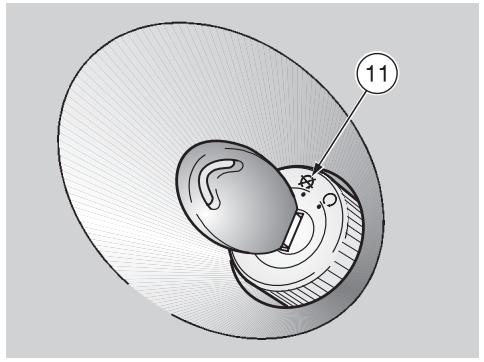
Turn the ignition switch to position "X" (11).
Keep the MODE push button pressed while turning the ignition switch to position "O" (12).

For the reverse switching, repeat these operations.
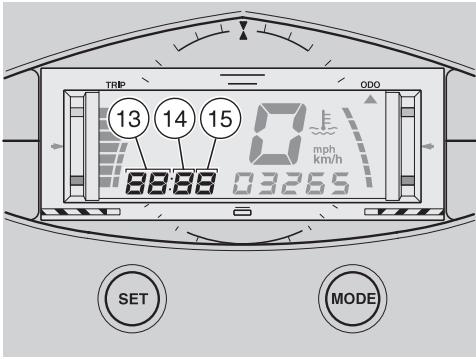
SETTING THE CLOCK (HOURS AND MINUTES)
Press the MODE push button for more than three seconds, the segments corresponding to the hours (13) will blink.

If the SET push button is pressed and released, the data ranged one by one, while if the push button is kept pressed, the loop over in cyclical sequences.
Press the SET push button and select the desired hour.
To confirm the hour setting, press the MODE push button for less than three seconds: the segment corresponding to the tens of minutes (14) will blink.
Press the SET push button and select the desired figure for the tens of minutes.
To confirm the setting of the tens of minutes, press the MODE push button for less than three seconds: the segment corresponding to the minutes (15) will blink.
Press the SET push button and select the desired minutes.
To confirm the minute setting, press and release the MODE push button.
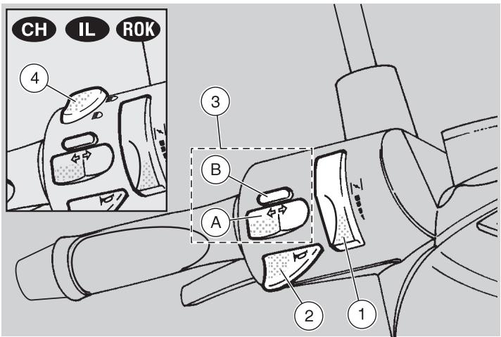
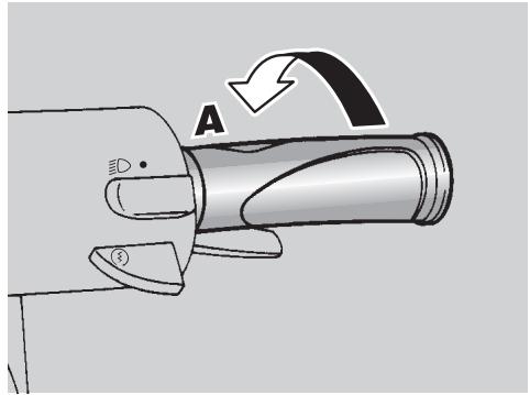
CONTROLS ON THE LEFT SIDE OF THE HANDLEBAR

The electrical parts work only when the ignition switch is in position "O".

The lighting system works only when the engine is running.
1) COLD START LEVER (H)
The starter for the cold start of the engine is operated by rotating the lever upwards.
To disconnect the cold start, bring the lever to its initial position.
2) HORN PUSH BUTTON (▶)
The horn is activated when the push button is pressed.
3) DIRECTION INDICATOR SWITCH (◇◇)
To indicate the turn to the left, move the switch (A) to the left; to indicate the turn to the right, move the switch (A) to the right.
To turn off the direction indicator, press the push button (B).
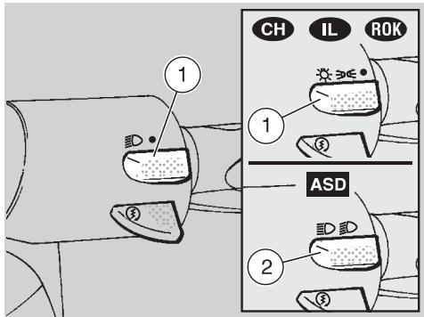
4) DIMMER SWITCH (E-D - E0) CH IL ROK
With the light switch in position “ 品 ”, see p. 19 (CONTROLS ON THE RIGHT SIDE OF THE HANDLEBAR): if the dimmer switch is in position “ 品 ”, the low beam is on, while if it is in position “ 品 ”, the high beam is on.
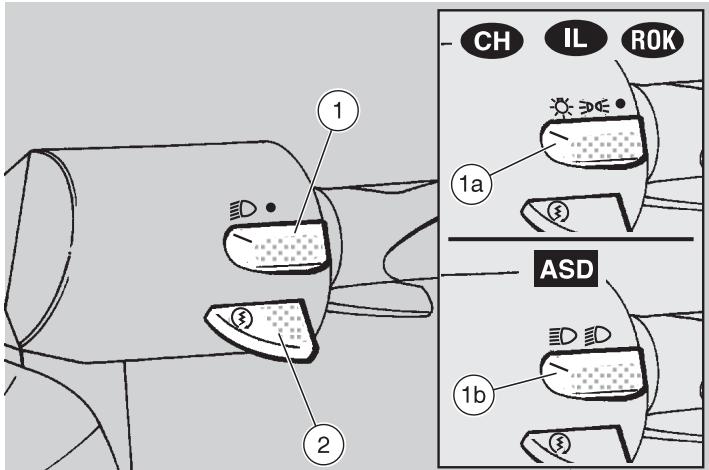
The electrical parts work only when the ignition switch is in position "O".

The lighting system works only when the engine is running.
1) LIGHT SWITCH (ED - ●)
When the light switch is in position “ ”, the lights are off; when the switch is in position “ ”, the rear parking light and the low beam are on.
1a) LIGHT SWITCH (C - - - - ) CH 1L ROK
When the light switch is in position “●”, the lights are off; when the switch is in position “ ≥ 0 ” the parking lights are on and when it is in position “ ≤ 0 ” the parking lights and the low or high beam are on. To turn on the low or high beam, use the dimmer switch, see p. 18 (CONTROLS ON THE LEFT SIDE OF THE HANDLEBAR).
When the dimmer switch is in position “ D ”, the low beam and the parking lights are on; when it is in position “ D ”, the high beam and the parking lights are on.

The lights can be switched off only by stopping the engine.
2) START PUSH BUTTON (③)
When the start push button is pressed and one of the brake levers (front or rear) is activated at the same time, the starter makes the engine run.
For the starting procedure, see p. 30 (STARTING).
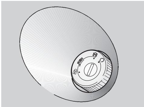
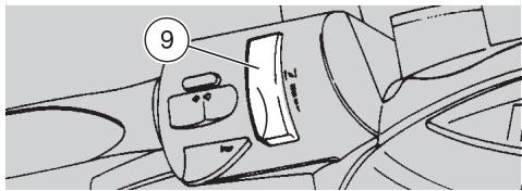
IGNITION SWITCH
The ignition switch is positioned on the right side, near the steering column.

The key (1) operates the ignition switch/steering lock and the lock.
Two keys are supplied together with the vehicle (one spare key).
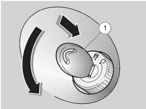
STEERING LOCK
Never turn the key to position "B" in running conditions, in order to avoid losing control of the vehicle.
OPERATION
To lock the steering:
Turn the handlebar completely leftwards.
Turn the key (1) to position " 品 " and press it.

Turn the key and steer the handlebar at the same time.
Rotate the key (1) anticlockwise (leftwards), steer the handlebar slowly until the key (1) reaches position "a".
Extract the key.
| Position | Function | Key removal |
| Steering lock | The steering is locked. It is neither possible to start the engine, nor to switch on the lights. | It is possible to remove the key. |
| × | Neither the engine, nor the lights can be switched on. | It is possible to remove the key. |
| ○ | The engine and the lights can be switched on. | It is not possible to remove the key. |
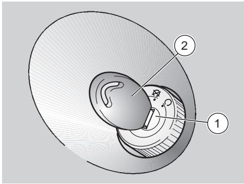
AUXILIARY EQUIPMENT
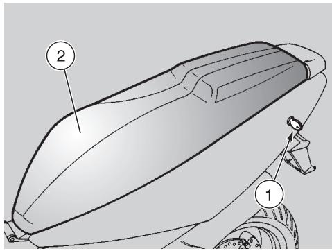
UNLOCKING/LOCKING THE SADDLE
To unlock and lift the saddle:
Position the vehicle on the centre stand.
Insert the key in the saddle lock (1).
Turn the key clockwise and raise the saddle (2).
Before lowering and locking the saddle, make sure that you have not left the key in the crash helmet/glove compartment.
To lock the saddle, lower and press it (without exerting too much pressure), thus making the lock snap shut.

Before leaving, make sure that the saddle is properly locked.
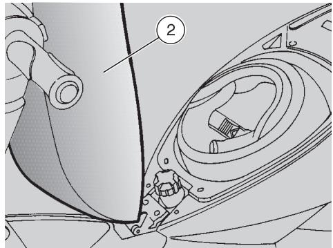
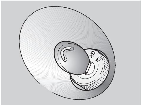
CRASH HELMET / GLOVE COMPARTMENT
Thanks to the crash helmet/glove compartment, you no longer have to carry the crash helmet or other objects with you every time you park the vehicle.
The compartment is positioned under the saddle.
To reach it:
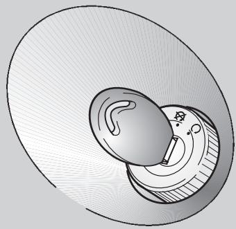
Raise the saddle (2), see beside (UNLOCKING/LOCKING THE SADDLE).

Position the helmet with the opening facing upwards, as in the figure.

Do not load the crash helmet/glove compartment too much.
Maximum allowed weight: 2.5kg
ANTI-THEFT HOOK
The anti-theft hook (3) is positioned on the right side of the vehicle.
To prevent the vehicle from being stolen, it is advisable to secure it with the aprilia "Body-Guard" armored cable OPT (4), available at any aprilia Official Dealer.

Do not use the hook to lift the vehicle or for any purpose other than securing the vehicle once it
has been parked.
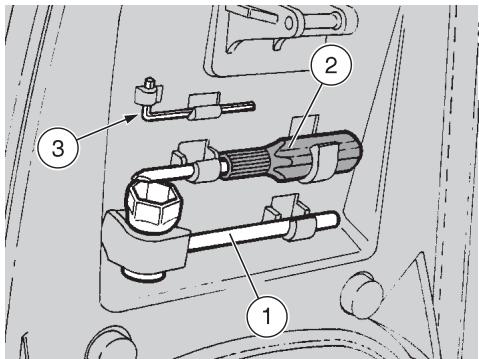
TOOL KIT
The tool kit is hooked to the underside of the saddle.
To reach it, proceed as follows:
Lift the saddle, see p.21 (UNLOCKING/LOCKING THE SADDLE).
The tool kit includes:
- n. 1 21 mm spark plug socket spanner (1)
- n. 1 double-ended, cross-/cut-headed screwdriver (2) type PH size 2 with handle
- n. 13 mm bent hexagon spanner (3)
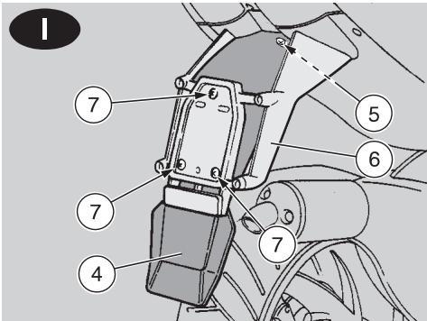
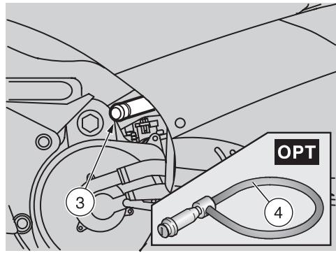
REAR MUDGUARD EXTENSION
The extension of the rear mudguard (4) is extremely useful when the road surface is wet, in fact it reduces the reach of the water spray caused by the rear wheel.

The rear mudguard extension (4)
is supplied as standard equip-nd is positioned in the crash hellove compartment.
For the installation, proceed as follows:
Raise the saddle, see p. 21 (UNLOCKING/LOCKING THE SADDLE).
Remove the rear mudguard extension (4) together with the screws and the relevant fastening nuts from the crash helmet / glove compartment.
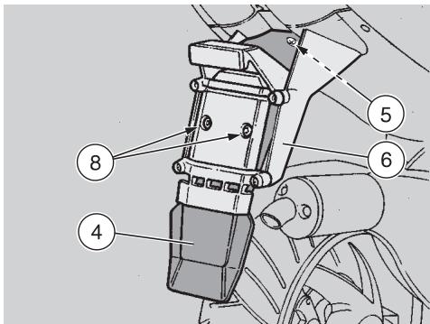
Unscrew and remove the screw (5).
Position the rear mudguard extension (4) inside the number plate-holder support (6).
Moderately tighten the screw (5).

Only for 1: the three screws (7) and the relevant nuts serve also fastening of the number plate.
Insert the three screws (7) and screw the relevant nuts.
Insert the two screws (8) and screw the relevant nuts.
Make sure that the rear mudguard extension (4) is positioned correctly.
Tighten the screw (5).
Tighten the three screws (7).
Tighten the two screws (8).

FUEL

The fuel used for internal combustion engines is extremely inflammable and in particular con
ditions it can become explosive.
It is important to carry out the refuelling and the maintenance operations in a well-ventilated area, with the engine off.
Do not smoke while refuelling or near fuel vapours, in any case avoid any contact with naked flames, sparks and any other heat source to prevent the fuel from catching fire or from exploding.
Further, prevent fuel from flowing out of the fuel filler, as it could catch fire when getting in contact with the red-hot surfaces of the engine.
In case some fuel has accidentally been spilt, make sure that the area has completely dried and before starting the vehicle verify that there is no fuel inside the fuel filler neck.
Since petrol expands under the heat of the sun and due to the effects of sun radiation, never fill the tank to the brim.
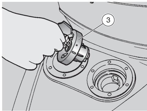
Screw the plug (3) up carefully after refuelling.
Avoid any contact of the fuel with the skin and the inhalation of vapours; do not swallow fuel or pour it from a receptacle into another by means of a tube.
KEEP AWAY FROM CHILDREN
Use only premium grade petrol (4 Stars UK), in conformity with the DIN 51600 standard, min. O.N. 98 (N.O.R.M.) and 88 (N.O.M.M.).
Use only unleaded petrol, in conformity with the DIN 51607 standard, min. O.N. 95 (N.O.R.M.) and 85 (N.O.M.M.).
FUEL TANK CAPACITY
(reserve included): 11.5 l
TANK RESERVE: 2 ± 0.5
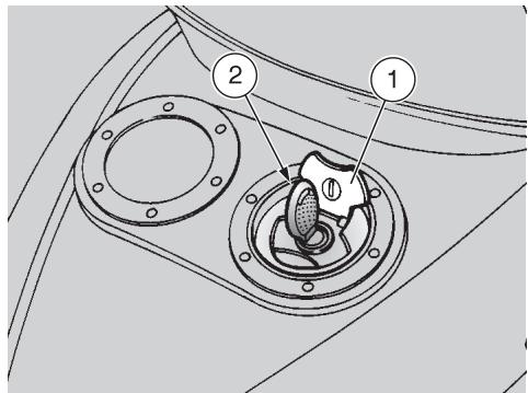
To refuel, proceed as follows:
Raise the cover (1).
Insert the key (2) in the fillercap lock.
Turn the key anticlockwise, pull and remove the fillercap (3).
Provide for refuelling.
2 STROKE OIL TANK

Remember: 1 mile = 1.6 km
1 km = 0.625 miles
Top up the mixer oil tank every 500~km
The vehicle is provided with a separate mixer that makes it possible to mix petrol with oil for the lubrication of the engine, see p. 64 (LUBRICANT CHART).
The reserve is indicated by the coming on of the 2 stroke oil reserve warning light "E" positioned on the dashboard, see p. 14 and 15 (INSTRUMENTS AND INDICATORS).

The use of the vehicle without 2 stroke oil causes serious damages to the engine.
If you run out of oil in the 2 stroke oil tank or if the mixer oil pipe has been removed, it is necessary to contact an aprilia Official Dealer, who will provide for bleeding the system.
This operation is indispensable, since the operation of the engine with air in the mixer oil system may cause serious damages to the engine itself.
To top up the 2-stroke oil tank, proceed as follows:
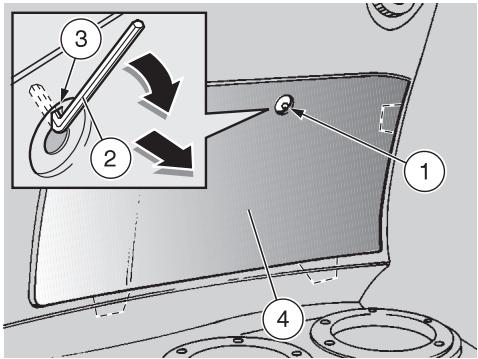
Remove the rear inspection cover, see p. 46 (REMOVING THE REAR INSPECTION COVER).
Remove the plug (1).
2 STROKE OIL TANK CAPACITY: 1.3 l
TANK RESERVE: 0.3 l

Wash your hands carefully after using the oil.
Do not dispose of the oil in the environment.
KEEP AWAY FROM CHILDREN.
BRAKE FLUID · recommendations

Sudden resistance or clearance problems on the brake lever may be due to problems in the hydraulic system.
For any doubt regarding the perfect functioning of the braking system and in case you are not able to carry out the usual checking operations, contact your aprilia Official Dealer.
Make sure that the brake disc and the friction elements are neither oily nor greasy, especially after maintenance or checking operations.
Check that the brake cable is neither twisted nor worn out.
Prevent water or dust from accidentally getting into the circuit.
In case maintenance operations are to be performed on the hydraulic circuit, it is advisable to use latex gloves.
If the brake fluid gets in contact with the skin or the eyes, it can cause serious irritations.
Carefully wash the parts of your body that get in contact with the liquid.
Consult a doctor or an oculist if the liquid gets in contact with your eyes.
Do not dispose of the brake fluid in the environment.
KEEP AWAY FROM CHILDREN

When using the brake fluid, take care not to spill it on the plastic or painted parts, since it irrepar damages them.

DISC BRAKES
The brakes are the parts that most ensure your safety and for this reason they must always be
perfectly working.
The brake fluid must be changed once a year by an aprilia Official Dealer.
This vehicle is provided with hydraulic disc brakes.
When the disc pads wear out, the level of the fluid decreases to automatically compensate for their wear.
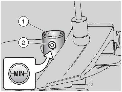
The brake fluid reservoirs (1) are positioned on the handlebar, near the brake lever couplings. Periodically check the brake fluid level in the reservoir (1) and the pad wear, see p. 43 (CHECKING THE BRAKE PAD WEAR).
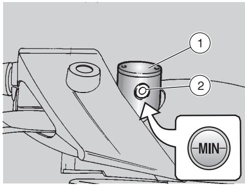

In normal operating conditions, the brake fluid never decreases below the "MIN" level.
If it does, do not use the vehicle and contact an aprilia Official Dealer.
CHECKING
To check the brake fluid level, proceed as follows:
Position the vehicle on the centre stand.
Rotate the handlebar leftwards, so that the fluid contained in the reservoir is parallel to the "MIN" mark stamped on the glass (2).
Make sure that the level of the brake fluid contained in the tank exceeds the "MIN" mark stamped on the glass (2).
If it does, do not use the vehicle and contact an aprilia Official Dealer.

In case of excessive movement of the brake lever, of excessive elasticity or in case there is air in
the circuit, contact your aprilia Official Dealer, since it may be necessary to bleed the system.

Remember: 1 mile = 1.6 km
1 km = 0.625 miles
COOLANT

Do not use the vehicle if the coolant is below the minimum prescribed level.

Remember: 1 mile = 1.6 km
1 km = 0.625 miles
Check the coolant level every 2000 km and after long rides; change it every 2 years.

Have the coolant changed by an aprilia Official Dealer.
The coolant is made up of 50% water and 50% antifreeze.
This mixture is ideal for most running temperatures and ensures good protection against corrosion.
It is advisable to keep the same mixture also in the hot season, since in this way losses due to evaporation are reduced and it is not necessary to top up very frequently.
The mineral salt deposits left in the radiator by evaporated water are thus reduced and the efficiency of the cooling system remains unchanged.
If the outdoor temperature is below 0^ check the cooling circuit frequently and if necessary increase the antifreeze concentration (up to maximum 60% ).

Do not remove the expansion tank cap when the engine is hot, since the coolant is under pres-nd its temperature is high.
If it gets in contact with the skin or with clothes it may cause severe burns and/or damages.
The coolant is noxious:
DO NOT SWALLOW IT.
KEEP AWAY FROM CHILDREN.
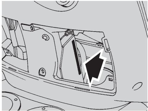
CHECKING AND TOPPING UP
Proceed as follows:
Raise the saddle, see p. 21 (UNLOCKING/LOCKING THE SADDLE).
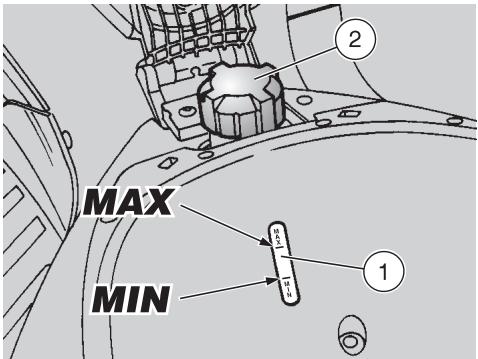
Make sure that the coolant level in the expansion tank is included between the "MIN" and "MAX" marks, by checking through the special slot (1) provided on the bottom of the crash helmet / glove compartment.
If the level is not included between the "MIN" and "MAX" marks, provide for topping up.
TOPPING UP

Proceed with care, releasing any residual pressure that may be present in the system.
Loosen the plug (2), by giving it about half a turn.
Wait for a few seconds, in order to release any residual pressure that may be present in the system.
Unscrew and remove the plug (2).
Top up until the fluid reaches approx. the "MAX" notch.
Do not exceed this level, otherwise the fluid will flow out of the tank when the engine is running.
Put back the filling cap (2).

In case of excessive consumption of coolant and in case the expansion tank remains empty, ensure that there are no leaks in the
Have it repaired by an aprilia Official Dealer.
TYRES
This vehicle is provided with tubeless tyres.

Periodically check the tyre inflation pressure at room temperature.
If the tyres are hot, the measurement is not correct.
Carry out the measurement especially after long rides.
If the inflation pressure is too high, the ground unevenness cannot be dampened and is therefore transmitted to the handlebar, thus compromising the driving comfort and reducing the road holding during turns.
If, on the contrary, the inflation pressure is too low, the tyre sides are under greater stress and the tyre itself may slip on the rim or it may become loose, with consequent loss of control of the vehicle.
In case of sudden braking the tyres could even get out of the rims. Further, the vehicle could skid while turning.
Check the surface and the wear of the tyres, since tyres in bad conditions can impair both the grip and the controllability of the vehicle.
Change the tyre when it is worn out or in case of puncture on the tread side, if the puncture is larger than 5mm
Use only tyres in the size suggested by aprilia, see p. 60 (TECHNICAL DATA).
Do not install tyres with air tube on rims for tubeless tyres and viceversa.
Make sure that the tyres always have their valve sealing caps on, to prevent them from suddenly going flat.
Change, reparation, maintenance and balancing operations are very important and should be carried out by qualified technicians with appropriate tools.
For this reason, it is advisable to have the above mentioned operations carried out by an aprilia Official Dealer or by a qualified tyre repairer.

If the tyres are new, they may still be covered with a slippery film: drive carefully for the first
Do not oil the tyres with unsuitable fluids.
INFLATION PRESSURE
SOLO RIDER
front: 180 kPa (1.8 bar)
rear: 200 kPa (2.0 bar)
RIDER AND ONE PASSENGER
(in the countries where this is allowed)
front: 200 kPa (2.0 bar)
rear: 220 kPa (2.2 bar)
MINIMUM TREAD深度LIMIT
front: 1.5 mm
rear: 1.5 mm


AUTOMATIC LIGHT SWITCHING VERSION ASD
The vehicles provided with the Automatic Switch-on Device can be immediately recognized, since the lights come automatically on as soon as the engine is started.
For this reason the light switch is replaced by a dimmer switch.
The lights can be switched off only by stopping the engine.
For the versions with high beam, proceed as follows:
Before starting the vehicle, make sure that the dimmer switch is in position "D" (front low beam).
CATALYTIC SILENCER
Avoid parking the vehicle catalytic version near dry brush wood or in places easily accessible to children, as the catalytic silencer becomes extremely hot during use; be very careful and avoid any kind of contact before it has completely cooled down.
The catalytic vehicle is fitted with a silencer with metal catalytic converter of the "platinum-rhodium bivalent" type.
This device provides for the oxidation of the CO (carbon monoxide) and of the HC (unburned hydrocarbons) contained in the exhaust gases, changing them into carbon dioxide and steam, respectively.
Due to the catalytic reaction, the high temperature reached by the exhaust gases makes for the burning of the oil particles, thus keeping the silencer clean and eliminating the exhaust fumes.
To have the catalytic converter function correctly and for long and to reduce possible problems regarding the soiling of the thermal unit and of the exhaust, it is necessary to avoid covering long distances with the engine running at constantly low rpm.
It is sufficient to alternate these periods with periods in which the engine runs at relatively high rpm, even if only for a few seconds, but rather frequently.
What has been stated above assumes particular importance for the cold starting of the engine: in this case, in order to reach a rpm regime sufficient to enable the "priming" of the catalytic reaction, just make sure that the temperature of the thermal unit has reached at least 50^ , which generally occurs a few seconds after starting the engine.

Do not use leaded petrol, since it causes the destruction of the catalytic converter.
INSTRUCTIONS FOR USE

Before departure, always carry out a preliminary checking of the vehicle, to make sure that it's correct and safely, see the listing table PRELIMINARY CHECK-OPERATIONS.
The non-performance of these checking operations can cause severe personal injuries or damages to the vehicle.

Do not hesitate to consult your aprilia Official Dealer in case there is something you do not
understand about the functioning of some controls or in case you suspect or discover some irregularities.
It does not take long to carry out a check-up and this operation ensures you much more safety.
PRELIMINARY CHECKING OPERATIONS
| Component | Check | Page |
| Front and rear brake | Check the functioning, the fluid level and make sure there are no leaks. Check the wear of the pads. Top up, if necessary. | 24, 25, 43 |
| Accelerator | Make sure that it works smoothly and that it is possible to open and close it completely, in all steering positions. If necessary, adjust and/or lubricate it. | 47 |
| 2 stroke oil | Check and/or top up, if necessary. | 24 |
| Wheel/tyres | Check the tyre surface, the inflation pressure, wear and tear and any damage. | 27 |
| Brake levers | Make sure that they work smoothly. If necessary, lubricate the articulations. | 24, 25 |
| Steering | Make sure that the steering rotates smoothly, without any clearance or slackening. | 44 |
| Centre stand | Make sure that it works smoothly. When the stand is let up or pushed down, there must be no friction and the spring tension must bring it back to its normal position. If necessary, lubricate joints and hinges. | — |
| Fastening elements | Make sure that the fastening elements are not loose. If necessary, adjust or tighten them. | — |
| Fuel tank | Check the fuel level and top up, if necessary. Make sure there are no leaks or occlusions in the circuit. | 23 |
| Coolant | The coolant level in the expansion tank must be included between the “MIN” and “MAX” markings. Top up, if necessary. | 26 |
| Lights, warning lights, horn and electric devices | Check the proper functioning of all the devices. Change the bulbs or intervene in case of failure. | 49 ÷ 56 |

STARTING

Exhaust gases contain carbon monoxide, which is extremely noxious if inhaled.
Avoid starting the vehicle in closed or badly-ventilated rooms.
The non-observance of this warning may cause loss of consciousness or even lead to death by asphyxia.
Do not get on the vehicle for the starting.
ELECTRIC STARTING
Position the vehicle on the centre stand.
Make sure that the light switch (1) is in position"
ASD Make sure that the dimmer switch (2) is in position
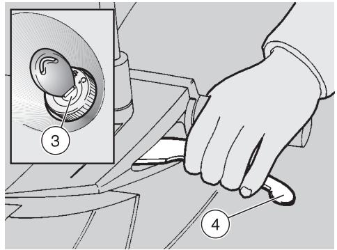
Turn the ignition switch (3) to position "O".
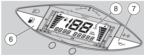
When the ignition key is rotated to position "O", the low fuel warning light ^ (6), the 2-stroke oil reserve warning light **7 and the entire display (8) come on for a few seconds, thus checking the operation of the system. If after this check the 2-stroke oil reserve warning light ** remains on, provide for topping up, see p. 24 (2 STROKE OIL TANK).
Lock at least one wheel, by pulling a brake lever (4).
If this operation is not carried out, the start relay receives no current and therefore the engine does not start.
Press the start push button "③" (5) without accelerating, then release it as soon as the engine starts.
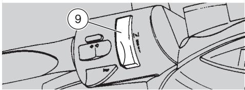
If the starting is carried out with cold engine, rotate the cold start lever "I" (9) upwards.

Avoid pressing the start push button "⑤" (5) when the engine is running: this may damage the
starter.
Do not accelerate and pull the brake levers at the same time until you move off.

Do not start abruptly when the engine is still cold.
To limit the emission of exhaust gases and fuel consumption, warm the engine up by running at slow speed for the first miles.
Once the engine has warmed up, see p. 15 (Coolant temperature indicator ""), rotate the cold start lever " " (9) downwards.
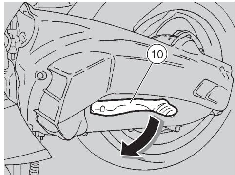
KICK START
For the kick start, proceed as follows:
Position the vehicle on the centre stand.
Move to the left side of the vehicle.
Make sure that the light switch (1) is in position"
ASD Make sure that the dimmer switch (2) is in position .
Turn the ignition switch (3) to position "O".
When the ignition key is rotated to position "O", the low fuel warning light "B" (6), the 2-stroke oil reserve warning light "C" (7) and the entire display (8) come on for a few seconds, thus checking the operation of the system. If after this check the 2-stroke oil reserve warning light "C" remains on, provide for topping up, see p. 24 (2 STROKE OIL TANK).

To avoid losing control of the vehicle during the starting, lock both wheels by putting on the brake levers (4).

Do not push down the kick starter with the engine on.
Push down the kick starter (10) with your right foot, releasing it immediately. If necessary, repeat the operation until the engine starts.
STARTING AFTER A LONG PERIOD OF INACTIVITY
After a long period of inactivity, proceed as follows:
Carry out the first five operations prescribed for the electric starting, see p. 30 (ELECTRIC STARTING).
Make the starter run for about 10 seconds, in order to ensure the filling up of the float chamber.
To start the engine:
Rotate the cold start lever "I" (9) upwards.
Slightly open the throttle, then carry out the electric starting procedure (or KICK START).
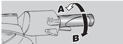
DEPARTURE AND DRIVE
This vehicle is not suitable for offroad use: aprilia declines any responsibility for any damage to persons, properties and/or the vehicle due to the improper use of the vehicle itself.
Release the throttle grip (pos. A), put on the rear brake, then move the vehicle down the stand.
Get on the vehicle, keeping at least one foot on the ground in order not to lose balance.
Properly adjust the inclination of the rear-view mirrors.
To leave, release the brake lever and accelerate by gently rotating the throttle grip (pos. B); the vehicle will start moving.
Avoid opening and closing the throttle grip repeatedly and continuously, so that you do not accidentally lose control of the vehicle.
If you have to brake, close the throttle and put on both brakes in order to obtain uniform deceleration, properly exerting pressure on the braking parts.
By putting on the front brake only or the rear brake only, you reduce the braking force considerably, thus running the risk of locking one wheel and consequently losing grip.
Before beginning to turn, slow down or brake driving at moderate and constant speed or accelerating slightly; avoid braking at the last moment: it would be very easy to skid.
If the brakes are operated continuously on downhill stretches, the friction surfaces can overheat, thus reducing the braking efficiency.
Never drive with the engine off!
In case of wet ground or scarce wheel grip (snow, ice, mud, etc.), drive slowly, avoiding sudden briskings or manoeuvres that could make you lose grip and fall down.

Pay the utmost attention to any obstacle or variation of the ground.
Uneven roads, rails, manhole covers, indications painted on the road surface, building site metal plates become rather slippery by rain. For this reason all these obstacles have to be carefully avoided, driving smoothly and bending the vehicle as little as possible.
Always use the turn indicators timely when you intend to change lane or direction, avoiding sharp and dangerous movements.
If the 2 stroke oil reserve warning light "..." (1) comes on during the normal functioning of the engine, this means that the 2 stroke oil reserve is being used; in this case, top up the mixer oil tank, see p. 24 (2 STROKE OIL TANK).
If the lit area on the coolant temperature indicator scale " 已 (2) reaches the red mark (right upper side) and blinks, stop the engine and check the coolant level, see p. 26 (COOLANT).
RUNNING-IN

Remember: 1 mile = 1.6 km
1 km = 0.625 miles

After the first 500 kilometres, carry out the checking operations indicated in the column "Af
ter running-in" of the REGULAR SERVICE INTERVALS CHART, see p. 35, in order to avoid hurting yourself or other people and/or damaging the vehicle.
The running-in of the engine is primary to ensure its correct functioning and its correct functioning. If possible, drive on hilly roads and/or roads with many bends, so that the engine, the suspensions and the brakes undergo a more effective running-in.
For the first 500km ,keep to the following indications:
0-300 km
Do not keep the throttle grip open more than one half for long stretches.
300-500 km
Do not keep the throttle grip open more than three-fourths for long stretches.
STOPPING

If possible, avoid stopping abruptly, slowing down suddenly and braking at the last moment.
Release the throttle grip (pos. A) and gradually put on the brakes to stop the vehicle.
In case of a brief stop, keep at least one brake on.
PARKING

Park the vehicle on firm and flat ground, to prevent it from falling down.
Neither lean the vehicle against walls, nor lay it on the ground.
Make sure that the vehicle and especially its red-hot parts do not represent a danger for persons and children.
Do not leave the vehicle unattended when the engine is on or the key is inserted into the ignition switch.
Do not sit on the vehicle when the stand is down.
Stop the vehicle, see beside (STOPPING).
Turn the ignition switch (1) to position "8".
Position the vehicle on the stand, see p. 34 (POSITIONING THE VEHICLE ON THE STAND).

It is not necessary to close the fuel tap when the engine is off, it is equipped with an automatic ring system.

Never leave the key in the ignition switch.
Lock the steering, see p. 20 (STEERING LOCK) and extract the key (2).
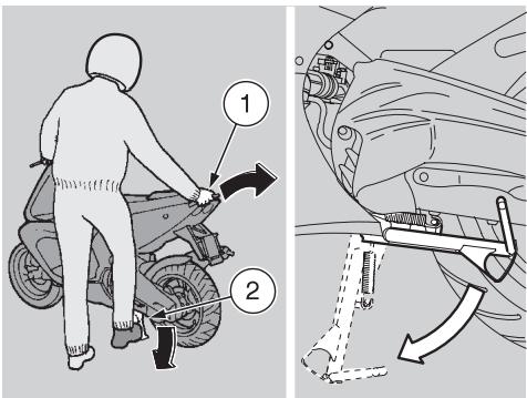
POSITIONING THE VEHICLE ON THE STAND
Carefully read p. 33 (PARKING).
CENTRE STAND
Grasp the left handgrip and the rear grab rail (1).
Push down the stand lever (2).

Make sure that the vehicle is stable.

SUGGESTIONS TO PREVENT THEFT
NEVER leave the ignition key inserted and always use the steering lock.
Park the vehicle in a safe place, possibly in a garage or a protected place.
If possible, use the appropriate aprilia "Body-Guard" armored cable OPT, or an additional anti-theft device.
Make sure that all documents are in order and the road tax has been paid.

Write down your personal data and telephone number in the space provided in this page, to facilitate the identification of the owner in case of finding after theft.
SURNAME:
NAME:
ADDRESS:
TELEPHONE NO:
Very often stolen vehicles are identified thanks to the data written on the use/maintenance manual.
MAINTENANCE

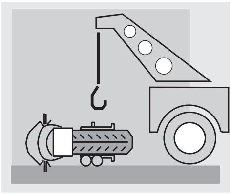
Before beginning any maintenance operation or any inspection of the vehicle, stop the en extract the key from the ignition wait until the engine and the ex system have cooled down and if he lift the vehicle by means of the car equipment, on firm and flat bed. Keep away from the red-hot of the engine and of the exhaust in, in order to avoid burns.
The vehicle is made up of not edible parts. Never bite, suck, chew or swallow any part of the vehicle for any reason.

If not expressly indicated otherwise, for the reassembly of the units repeat the disassembly operation reversing their order.
Ordinary maintenance operations can usually be carried out by the user, but sometimes a basic knowledge of mechanics and specific tools are required.
If you need assistance or technical advice, consult your aprilia Official Dealer, who can ensure you prompt and accurate servicing. After any maintenance operation, carry out the "Preliminary checking operations", see p. 29 (PRELIMINARY CHECKING OPERATIONS).

Remember: 1 mile = 1.6 km
1 km = 0.625 miles
REGULAR SERVICE INTERVALS CHART
| COMPONENT | After running-in (500 km) | Every 4000 km or 8 months | Every 8000 km or 16 months |
| Rear shock absorber | C | C | |
| Battery/electrolyte level | C | C | |
| Spark plug | C | C | S |
| Carburettor - idling | R | C | |
| Driving belt | C | ||
| Steering column bearings | C | C | |
| Wheel bearings | C | ||
| Removal of deposits from the exhaust | P | ||
| Air cleaner | C | P | |
| Accelerator operation | C | C | |
| Brake locking operation | C | C | |
| Braking systems | C | C | |
| Stop light switch | C | ||
| Brake fluid | every year: S | ||
| Brake fluid | C | ||
| Coolant | every 2000 km: C / every 2 years : S | ||
| 2 stroke oil | every 500 km: C | ||
| Transmission oil | S | every 3000 km or 6 months: C | every 12000 km or 2 years: S |
| Light direction - operation | C | ||
| Tyres - inflation pressure | every month: R | ||
| Wheels/tyres | C | ||
| Nut, bolt, screw tightening | C | C | |
| Front and rear suspension | C | C | |
| 2 stroke oil reserve warning light | C | C | |
| Fuel pipe | C | ||
| Mixer oil pipe | C | C | |
| Front and rear brake pad wear | C | every 2000 km: C | |
| C = check, clean, adjust, lubricate or change, if necessary; P = clean; S = change; R = adjust. Carry out the maintenance operations more frequently if you use the vehicle in rainy and dusty areas or on uneven ground. Have maintenance operations on the components indicated by carried out by aprilia Official Dealers ONLY. | |||
IDENTIFICATION DATA
It is a good rule to write down the frame and engine numbers in the space provided in this manual.
The frame number can be used for the purchase of spare parts.

Do not alter the identification numbers if you do not want to in
cur severe penal and administrative sanctions. In particular, the alteration of the frame number results in the immediate invalidity of the guarantee.
ENGINE NUMBER
The engine number is stamped near the transmission oil filling cap.
Engine no.
FRAME NUMBER
The frame number is stamped on the right side of the steering column plate. To read it, it is necessary to remove the front inspection cover, see p. 46 (REMOVING THE FRONT INSPECTION COVER).
Frame no.
AIR CLEANER

Do not use petrol or inflammable solvents to wash the air cleaner, in order to avoid fires or explosions.
Carefully read p. 35 (MAINTENANCE).

Remember: 1 mile = 1.6 km
1 km = 0.625 miles
Check the conditions of the air cleaner and clean it monthly or every 4000km depending on the conditions in which the vehicle is used.
If the vehicle is used on dusty or wet roads, the cleaning operations and any replacement should be carried out more frequently.
To clean the filtering element it is necessary to remove the whole filter casing from the vehicle.
REMOVAL
Remove the left inspection cover, see p. 46 (REMOVING THE RIGHT AND LEFT INSPECTION COVERS).
Insert the spanner in the appropriate hole (1), while unscrewing and removing the screw (2) with the relevant washer.

Upon reassembly, position the rear brake cable eyelet (3) cor
rectly.
Unscrew and remove the screw (4) with the relevant washer.
Loosen the screw (5) of the air manifold clamp.
Grasp the air manifold in correspondence with the clamp and pull it, thus removing the whole air cleaner casing.
CLEANING THE AIR FILTER
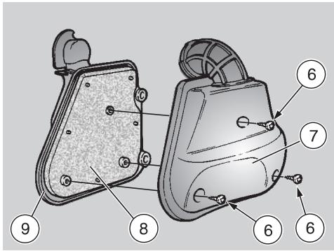
Unscrew the three screws (6).
Remove the filter case cover (7) and extract the filtering element (8).
To clean the filtering element use clean, non-inflammable solvents or solvents with high volatility point, then let it dry thoroughly.
Apply a filter oil or a thick oil (SAE 80W-90) on the whole surface of the filtering element, then squeeze it to eliminate the oil in excess.

The filter must be well impregnated, though not dripping.
Clean the inside of the filter casing cover (7) and of the filter casing (9) with a cloth.

CHECKING THE TRANSMISSION OIL LEVEL
In case of oil leaks or malfunctions, contact your aprilia Official Dealer.
DO NOT DISPOSE OF THE TRANSMISSION OIL IN THE ENVIRONMENT.
Carefully read p. 35 (MAINTENANCE).

Remember: 1 mile = 1.6 km
1 km = 0.625 miles
To check the transmission oil level, carry out the following operations every 3000 km or every 6 months:
Drive for a few miles until the engine reaches the normal running temperature, see p. 15 (Coolant temperature indicator "E"), then stop it.
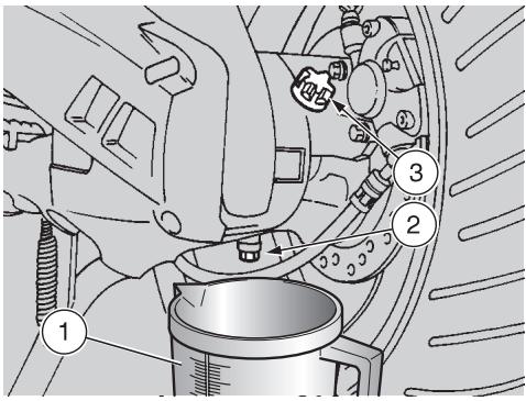
Position the vehicle on the centre stand.
Put a graduated container (1) with at least 120~cm^3 capacity under the drain plug (2).
Unscrew the filling cap (3) and the oil drain plug (2).
Let all the oil flow out of the oil pan.
Measure the quantity and if it is less than 110~cm^3 top up by adding the lacking quantity, see p.64 (LUBRICANT CHART).
Tighten the drain plug (2).
Provide for filling up, using the oil collected into the graduated container (1).
Tighten the filling cap (3).


Tighten the filling cap and the drain plug thoroughly and make sure that there are no oil leaks.
Periodically check that there are no leaks in correspondence with the oil pan cover seal.
Do not use the vehicle with insufficient lubrication or with contaminated or unsuitable lubricants, since this would accelerate the wear of the moving parts and may also cause irreparable failures.

CHANGING THE TRANSMISSION OIL

In case of oil leaks or malfunctions, contact your aprilia Official Dealer.
DO NOT DISPOSE OF THE TRANSMISSION OIL IN THE ENVIRONMENT.
Put it in a sealed container and take it to the filling station where you usually buy it or to an oil salvage center.
Carefully read p. 35 (MAINTENANCE).

Remember: 1 mile = 1.6 km
1 km = 0.625 miles
To ensure the efficiency and long life of the vehicle, it is necessary to change the oil after the first 500km and successively every 12000 km or every 2 years.

Proceed as follows:
Drive for a few miles until the engine reaches the normal running temperature, see p. 15 (Coolant temperature indicator "土"), then stop the engine.
Position the vehicle on the centre stand.
Put a graduated container (1) with at least 120~cm^3 capacity under the drain plug (2).
Unscrew the filling cap (3) and the oil drain plug (2).
Let all the oil flow out of the oil pan.
Tighten the drain plug and add 110~cm^3 of oil, see p. 64 (LUBRICANT CHART).
Tighten the filling cap (3).


Tighten the filling cap and the drain plug thoroughly and make sure that there are no oil leaks.
Periodically check that there are no leaks in correspondence with the oil pan cover seal.
Do not use the vehicle with insufficient lubrication or with contaminated or unsuitable lubricants, since this would accelerate the wear of the moving parts and may also cause irreparable failures.
FRONT WHEEL
DISASSEMBLY
Carefully read p. 35 (MAINTENANCE).
While disassembling the wheel, be careful not to damage the brake pipe, the disc and the pads.
To disassemble the front wheel, proceed as follows:
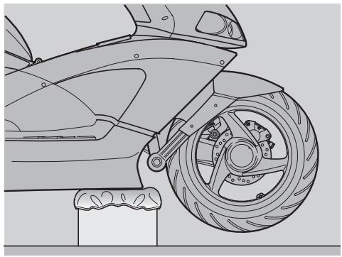
Position the vehicle on the centre stand.
Prepare a 190 mm high support, the base of which must measure 200 × 200 ~mm .
Place the support under the vehicle and a spongy cloth between them, so that the front wheel can move freely and the vehicle cannot fall down.

Make sure that the vehicle is stable.
Remove the front brake caliper, see p. 43 (REMOVING THE FRONT AND REAR BRAKE CALIPERS).
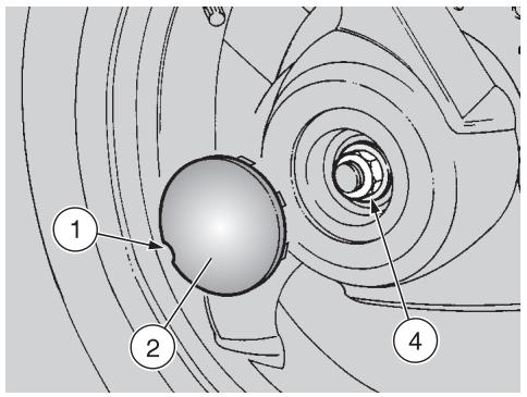
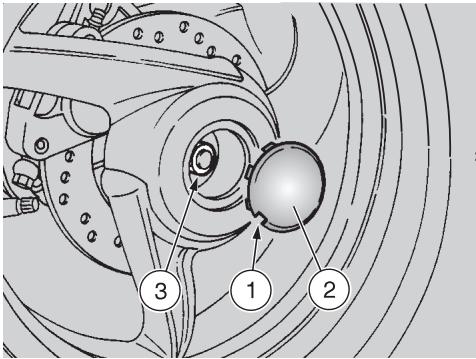
Introduce the screwdriver in the slot (1), lever and remove the cover (2).
Lock the wheel pin (3) by means of a spanner.
Unscrew and remove the nut (4), taking the washer.
Wheel nut (4) driving torque: 120 Nm (12 kgm).
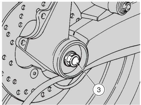
Push the wheel pin (3), by carefully acting on the threaded end and using a rubber hammer if necessary.

Check the arrangement of the odometer control (5), in order to be to reassemble it correctly.
Support the front wheel and extract the wheel pin (3) manually.

Do not force the odometer control cable.
Move the wheel rightwards (in the travelling direction).
Disconnect the odometer control (5).
Remove the wheel.
REASSEMBLY
Carefully read p. 35 (MAINTENANCE).

While reassembling the wheel, be careful not to damage the brake pipe, the disc and the pads.
To reassemble the front wheel, proceed as follows:

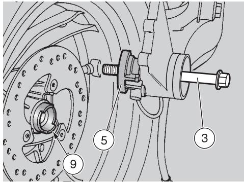
Uniformly apply a moderate quantity of grease on the wheel and a greater quantity of grease on the dust cover (6) of the odometer (10), see p. 64 (LUBRICANT, MT).
Correctly position the odometer control (5) with the relevant seat (7) inserted in the antirotation pin (8), while partially introducing the wheel pin (3) from the left side (travelling direction).
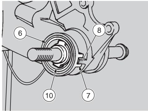
Make sure that the wheel hub (9) is perfectly clean, either inside and outside.

Upon reassembly, do not force the wheel against the odometer control (5), to prevent the wheel) from damaging the teeth (10).
Bring the wheel near the end of the suspension arm, raise it and insert the wheel pin (3) completely.
Rotate the wheel moderately and try to find the point in which it can be fitted completely, with the wheel hub (9) correctly coupled with the teeth (10).
Insert the washer, lock the rotation of the wheel pin (3) by means of a spanner, screw and tighten the nut (4).
Wheel nut (4) driving torque: 120 Nm (12 kgm).

Put back the cover (2) and fit it manually.
Remove the support from under the vehicle.

After reassembly, pull the front brake lever repeatedly and check the correct functioning of braking system.
Check the wheel centering.
Have the driving torques, centering and balancing of the wheel checked by your aprilia Official Dealer, in order to avoid accidents that may be harmful for you and/or other people.
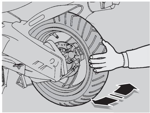
REAR WHEEL
DISASSEMBLY
Carefully read p. 35 (MAINTENANCE).
Remove the exhaust silencer, see p. 45 (REMOVING THE EXHAUST SILENCER).
Insert the screwdriver in the slot (1), lever and remove the cover (2).
To unscrew the wheel nut (3), it is necessary to lock the rotation of the wheel.
Pull the rear brake lever (4) completely, then put a small piece of cardboard (5) on the grip and keep the rear brake lever pulled by holding it against the grip by means of a plastic band (6).
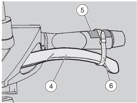
Loosen the wheel nut (3).
Wheel nut (3) driving torque: 110 Nm (11 kgm).
Remove the plastic band (6) and take the piece of cardboard (5).
Release the rear brake lever.
Remove the rear brake caliper, see p. 43 (REMOVING THE FRONT AND REAR BRAKE CALIPERS).
Unscrew and remove the wheel nut (3) and the washer.
Upon reassembly, uniformly apply a moderate quantity of grease on the wheel pin, see p. 64 (LUBRICANT CHART) and replace the wheel nut (special type) with a new one.
Withdraw the wheel.

Use aprilia Genuine Spare Parts only.

After reassembly, pull the rear brake lever repeatedly and check the correct functioning of braking system.
Check the wheel centering.
Have the driving torques, centering and balancing of the wheel checked by your aprilia Official Dealer, in order to avoid accidents that may be harmful for you and/or other people.
Remember: 1 mile = 1.6 km
1 km = 0.625 miles

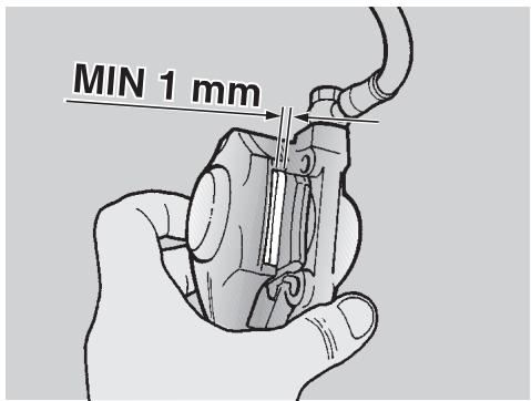
The following information refers to a single braking system, but is said for both.
Check the brake pad wear after the first 500km and successively every 2000km .
The wear of the brake pads depends on the use, on the kind of drive and on the road. The wear will be greater when the vehicle is driven on dirty or wet roads.
To carry out a rapid checking of the wear of the front pads, proceed as follows:
Remove the involved brake caliper, see beside (REMOVING THE FRONT AND REAR BRAKE CALIPERS).
Carry out a visual check on the pads.
If the thickness of the friction material (even of one pad only) has reduced to about 1mm , replace both pads.

Have the pads changed by your aprilia Official Dealer.
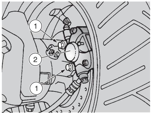
REMOVING THE FRONT AND REAR BRAKE CALIPERS
Carefully read p. 35 (MAINTENANCE).

Upon disassembly, take care not to damage the brake pipe, disc and pads.

The following information refers to a single braking system, but id for both.
Position the vehicle on the centre stand.
Rotate the wheel manually, so that the space between two spokes of the rim coincides with the brake caliper.
Unscrew and remove the two screws (1).
Brake caliper screw (1) driving torque: 25 Nm (2.5 kgm).

Never pull the rear brake lever after removing the brake caliper, otherwise the caliper pistons
may go out of their seats, thus causing the outflow of the brake fluid.
In this case consult your aprilia Official Dealer, who will carry out the proper maintenance operation.
Remove the brake caliper (2), by carefully withdrawing it from the brake disc.

After reassembly, pull the rear brake lever repeatedly and check the correct functioning of
the braking system.
CHECKING THE STEERING
Carefully read p. 35 (MAINTENANCE).
Every now and then it is advisable to check the steering, in order to verify if there are slacks.
To check the steering it is necessary to:
Position the vehicle on the centre stand.
Prepare a 190 mm high support, the base of which must measure 200 × 200 ~mm .
Place the support under the vehicle and a spongy cloth between them, so that the front wheel can move freely and the vehicle cannot fall down.

Make sure that the vehicle is stable.
Shake the front part of the vehicle in the travelling direction.

Do not shake the front part of the vehicle excessively, otherwise may take in consideration the moment of the stand, thus observing correct slack.
Repeat the previous operation more than once.
If you find that there is a considerable slack, contact your aprilia Official Dealer to restore the optimal steering conditions.
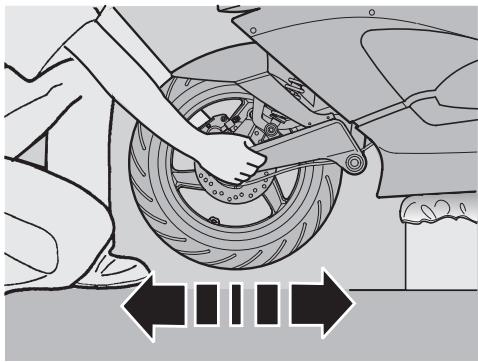
CHECKING
THE ENGINE FULCRUM AXIS
Carefully read p. 35 (MAINTENANCE).
Periodically check the slack existing between the engine pin bushings.
To carry out this operation, proceed as follows:
Position the vehicle on the centre stand.
Shake the wheel perpendicularly to the direction of travel (see figure).
If you find any slack, make sure that all the fastening elements of the fulcrum axis are well tightened.

If the slack persists, contact your aprilia Official Dealer.
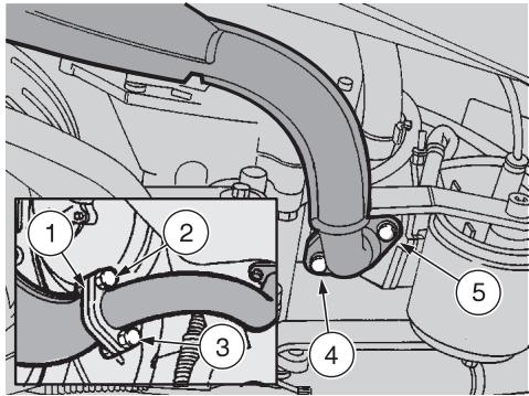
REMOVING THE EXHAUST SILENCER
Carefully read p. 35 (MAINTENANCE).
Position the vehicle on the centre stand.
Before performing the operations described below, let the engine and the exhaust silencer cool down until they have reached room temperature, in order to avoid burns.
If the additional flange (1) is provided, DO NOT unscrew the screws (2) and (3), but follow the procedure described here below.
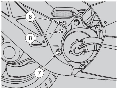
Unscrew and remove the screws (4) and (5).
Screw (4) and (5) driving torque: 12 Nm (1.2 kgm).
Unscrew and remove the mudguard fastening screw (6).
Unscrew and remove the two screws (7) and (8) that fasten the exhaust silencer to the engine.
Screw (7) and (8) driving torque: 25 Nm (2.5 kgm).
Remove the exhaust silencer.
Upon reassembly, replace the gasket between the exhaust manifold and the silencer with a new one.
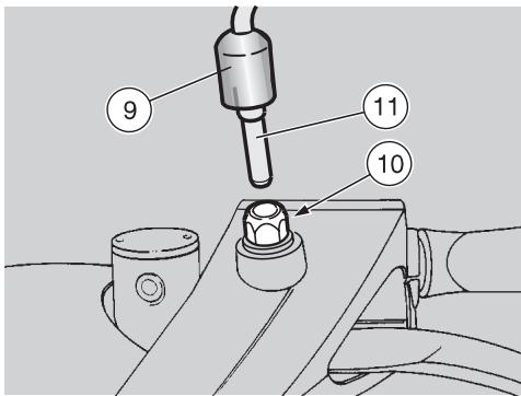
REMOVING THE REAR-VIEW MIRROR
Carefully read p. 35 (MAINTENANCE).
Position the vehicle on the centre stand.
For the countries where the use of the second rear-view mirror is prescribed: the following operations refer to a single mirror, but are valid for both.
Lift the protection element (9).
Loosen the nut (10) by giving it about one turn.
Withdraw the rear-view mirror (11).
When the rear-view mirror (11) has been removed, do not tighten the nut (10), in order not to damage the plastic part of the handlebar cover.
REMOVING THE FRONT INSPECTION COVER
Carefully read p. 35 (MAINTENANCE).
Handle the painted components with care and avoid scraping or damaging them.
Position the vehicle on the centre stand.
Unscrew and remove the screw (1).

Proceed with care.
Do not damage the tangs and/or their seats.
Introduce the short part of the bent hexagon spanner (2) in the appropriate seat (3), rotate the spanner downwards, pull it and remove the front inspection cover (4).
Upon reassembly, correctly insert the tangs in their seats.
REMOVING THE RIGHT AND LEFT INSPECTION COVERS
Carefully read p. 35 (MAINTENANCE).
Position the vehicle on the centre stand.
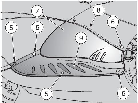
Unscrew and remove the four screws (5).
Only for the left inspection cover: unscrew and remove the screw (6).
Remove the inspection cover (7) by withdrawing it sideways.

Upon reassembly, correctly insert the upper part (8) in its seat.
Take the mat (9).

Upon reassembly, correctly positioning the mat (9) under the inspecover (7), with the antislip profiles on the appropriate seats.
REMOVING THE REAR INSPECTION COVER
Carefully read p. 35 (MAINTENANCE).
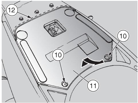
Raise the saddle, see p. 21 (UNLOCKING/LOCKING THE SADDLE).
Unscrew and remove the two screws (10).
Lift the front part of the inspection cover (11) and remove it by withdrawing it in the travelling direction.

Upon reassembly, correctly insert the rear part (12) in its seat.
IDLING ADJUSTMENT
Carefully read p. 35 (MAINTENANCE).

Remember: 1 mile = 1.6 km
1 km = 0.625 miles
Adjust the idling after the first 500km and every time it is irregular.
To carry out this operation, proceed as follows:
Drive for a few miles until the engine reaches the normal running temperature, see p. 15 (Coolant temperature indicator "上"), then stop the engine.
Position the vehicle on the centre stand.
Remove the right inspection cover, seep. 46 (REMOVING THE RIGHT AND LEFT INSPECTION COVERS).
Connect an electronic revolution counter to the spark plug cable.
Start the engine.
The minimum speed of the engine (idling) must be about 1800 ± 100 rpm; in this case the engine does not make the rear wheel rotate.
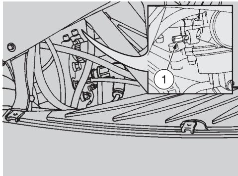
If necessary:
Work on the right side of the vehicle, using a small-tip, but sufficiently long screwdriver.
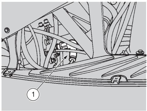
Act on the adjusting screw (1) positioned on the carburettor.
By SCREWING IT (clockwise), you increase the engine rpm.
By UNSCREWING IT (anticlockwise), you decrease the engine rpm.
Twist the throttle grip, accelerating and decelerating a few times to make sure that it functions correctly and to check if the idling speed is constant.

Do not act on the air adjusting screw, to avoid variations of the action setting.

If necessary, contact your aprilia Official Dealer.
ADJUSTING
THE ACCELERATOR CONTROL
Carefully read p. 35 (MAINTENANCE).
The ideal slack of the accelerator control should be about 2-3 mm.
To adjust the slack, proceed as follows:
Position the vehicle on the centre stand. Work on the left rear side of the vehicle and precisely on the adjusting screw positioned on the carburettor.

DO NOT withdraw the protection element of the cold start control 2).

Proceed with care. Do not bend or force the cables or the components of the carburettor.
Remove the protection element (3).
Loosen the nut (4) (by turning it clockwise).
Act on the adjuster (5), positioned at the beginning of the accelerator control cable.
After the adjustment:
Tighten the nut (4) (by turning it anticlockwise), thus locking the adjuster (5) and put back the protection element (3).
SPARK PLUG
Carefully read p. 35 (MAINTENANCE).

Remember: 1 mile = 1.6 km
1 km = 0.625 miles
Check the spark plug after the first 500 km and successively every 4000 km; change it every 8000 km.
Periodically remove the spark plug and clean it carefully, removing carbon deposits; change it if necessary.
To reach the spark plug:
Remove the right inspection cover, see p. 46 (REMOVING THE RIGHT AND LEFT INSPECTION COVERS).
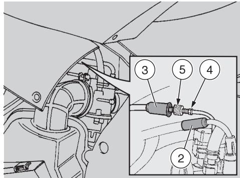
To remove and clean the spark plug:
Take off the spark plug cap (1).
Remove all the dirt from the base of the spark plug, then unscrew it with the spanner you will find in the tool kit and extract it from its seat, taking care that neither dust nor other substances enter the cylinder.
Make sure that there are neither carbon deposits, nor corrosion marks on the electrode and on the central porcelain part; if necessary, clean them with the special cleaners for spark plugs, with an iron wire and/ or a metal brush.
Energetically blow some air, in order to prevent the removed residues from getting into the engine.
If the spark plug has crackings on the insulating material, corroded electrodes or excessive deposits, it must be changed.
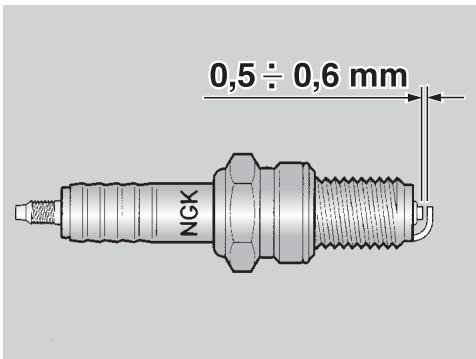
Check the spark plug gap with a thickness gauge.
The gap must be 0.5 ± 0.6 ~mm ; if necessary adjust it, carefully bending the earth electrode.
Make sure that the washer is in good conditions. With the washer on, screw the spark plug by hand in order not to damage the thread.
Using the spanner provided in the tool kit, tighten the spark plug, giving it half a turn to compress the washer.

The spark plug must be well tightened, otherwise the engine may overheat and be seriously ed.
Use the recommended type of spark plug only, see p. 60 (TECHNICAL DATA), in order not to compromise the life and performance of the engine.
Position the spark plug cap (1).
Put back the inspection cover.
BATTERY
Carefully read p. 35 (MAINTENANCE).

Remember: 1 mile = 1.6 km
1 km = 0.625 miles
Check the electrolyte level and the tightening of the terminals after the first 500km and successively every 4000km or 8 months.

ONLY FOR BATTERIES REQUIRING MAINTENANCE: the electrolyte in the battery is toxic and can and if it gets in contact with the can cause burns, since it con- fulphuric acid.
Wear protection clothes, a face mask and/or goggles during maintenance operations.
In case of contact with the skin, rinse with plenty of water.
In case of contact with the eyes, rinse with plenty of water for 15 minutes, then consult an oculist without delay.
If the electrolyte is accidentally swallowed, drink a lot of water or milk, then continue drinking milk of magnesia or vegetable oil and consult a doctor without delay.

The battery gives off explosive gases; keep it away from flames, sparks, cigarettes and any other type of heat.
During the recharging or the use, make sure that the room is properly ventilated and avoid inhaling the gases released during the recharging.
KEEP AWAY FROM CHILDREN

Never invert the connection of the battery cables.
Do not incline the vehicle too much, in order to avoid dangerous leaks of the battery fluid.
Connect and disconnect the battery with the ignition switch in position " 念 . Connect first the positive cable (+) and then the negative cable (-)
Disconnect following the reverse order. The electrolyte is corrosive.
Do not pour or spill it, especially on the plastic parts.
LONG INACTIVITY OF THE BATTERY
If the vehicle remains unused for a long period:
Remove the battery, see p. 50 (REMOVING THE BATTERY) and put it in a cool and dry place.
Recharge it completely, by using a trickle charge, see p. 51 (RECHARGING THE BATTERY).
If the battery remains on the vehicle, disconnect the cables from the terminals.
It is important to check the charge periodically (about once a month), during the winter or when the vehicle remains unused, in order to prevent the deterioration of the battery.
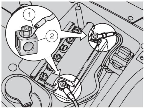
CHECKING AND CLEANING THE TERMINALS
Carefully read p. 49 (BATTERY).
Remove the rear inspection cover, see p. 46 (REMOVING THE REAR INSPECTION COVER).
Make sure that the cable terminals (1) and the battery terminals (2) are:
- in good conditions (and not corroded or covered with deposits);
covered with special grease or Vaseline.
If necessary:
Make sure that the ignition switch is in position "X".
Disconnect first the negative (-) and then the positive cable (+) .
Brush with a wire brush to eliminate any sign of corrosion.
Reconnect first the positive (+) and then the negative cable (-) .
Cover the terminals with special grease or Vaseline.
REMOVING THE BATTERY
Carefully read p. 49 (BATTERY).
Remove the rear inspection cover, see p. 46 (REMOVING THE REAR INSPECTION COVER).
Make sure that the ignition switch is in position "X".
Disconnect first the negative (-) and then the positive cable (+) .
Remove the battery breather pipe.
Remove the battery from its compartment and put it on a flat surface, in a cool and dry place.

Once it has been removed, the battery must be stored in a safe place and kept away from children.
CHECKING THE ELECTROLYT E LEVEL
Carefully read p. 49 (BATTERY).
Remove the battery from its compartment, see p. 50 (REMOVING THE BATTERY).
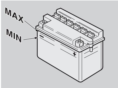
Make sure that the fluid level is included between the two "MIN" and "MAX" notches stamped on the battery side. Otherwise:
Unscrew and remove the element plugs.
Top up with distilled water only. Do not exceed the "MAX" mark, since the electrolyte level increases during the recharge.
Top up by adding distilled water.
RECHARGING THE BATTERY
Carefully read p. 49 (BATTERY).
Remove the battery from its compartment, see p. 50 (REMOVING THE BATTERY).
Unscrew and remove the element plugs.
Check the electrolyte level, see beside (CHECKING THE ELECTROLYTE LEVEL).
Connect the battery with a battery charger.
A recharge with an amperage equal to 1/10th of the battery capacity is recommended.
After the recharging operation, check the electrolyte level again and if necessary top up with distilled water.
Replace the element plugs.
Reinstall the battery only 5-10 minutes after disconnecting the recharge equipment, since the battery keeps sending out extremely inflammable hydrogen gas for a short lapse of time.
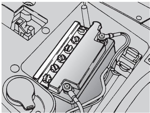
INSTALLING THE BATTERY
Carefully read p. 49 (BATTERY).
Put the battery in its container.
Connect the breather pipe.
Always connect the battery breather pipe, to prevent the sulphuric acid vapours from corroding the electric system, painted parts, rubber elements or gaskets when they exit the breather pipe itself.
Connect, in order, the positive (+) and negative (-) cable.
Cover the terminals with special grease or Vaseline.
Put back the rear inspection cover, see p. 46 (REMOVING THE REAR INSPECTION COVER).
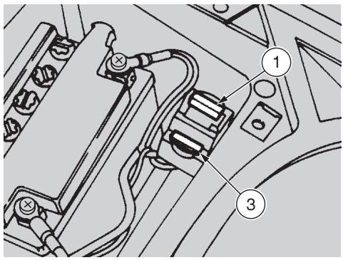
CHANGING THE FUSE
Carefully read p. 35 (MAINTENANCE).

Do not repair faulty fuses.
Never use fuses different from the recommended ones.
The use of unsuitable fuses may cause damages to the electric system or, in case of short circuit, even a fire.

If a fuse blows frequently, there is probably a short circuit or an pad in the electric system.
In this case it is advisable to consult an aprilia Official Dealer.
If an electric component does not work or works irregularly, or if the vehicle fails to start, it is necessary to check the fuse (1).
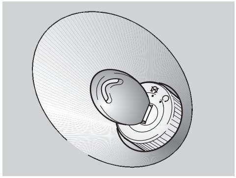
For the checking, proceed as follows:
Turn the ignition switch to position "☑", to avoid any accidental short circuit.
Remove the rear inspection cover, see p. 46 (REMOVING THE REAR INSPECTION COVER).
Extract the fuse (1) and check if the filament (2) is broken.
Before replacing the fuse, try to find out the cause of the trouble, if possible.
Then replace the damaged fuse with the spare fuse (3) or with a new one having the same amperage.

If you use one of the spare fuse (3), put a new fuse in the suitable
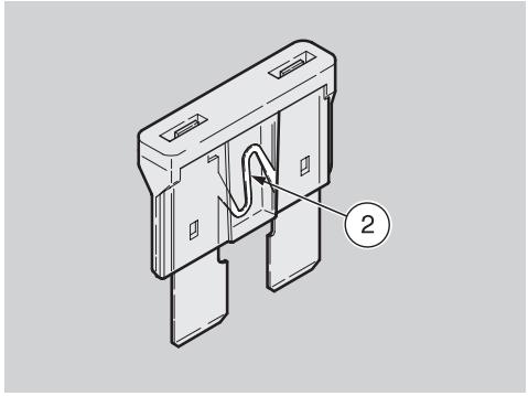
ARRANGEMENT OF THE FUSE
7.5 A fuse from the battery to:
all the electric loads, excluding the light circuit, which is fed with alternate current.
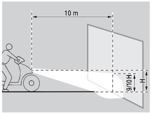
ADJUSTING THE VERTICAL HEADLIGHT BEAM
To rapidly check the correct direction of the beam, place the vehicle on flat ground, 10 m away from a wall.
Turn on the low beam, sit on the vehicle and make sure that the beam projected on the wall is slightly under the horizontal line of the headlight (about 9/10th of the total height).
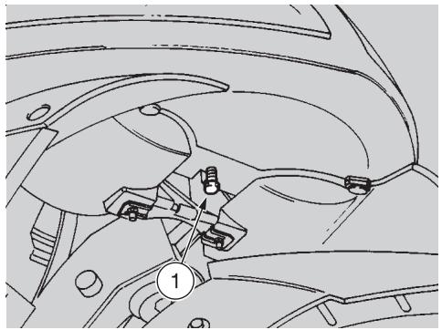
To adjust the headlight beam:
Act on the suitable screw (1) by means of a screwdriver.
By TURNING IT CLOCKWISE, you set the beam upwards.
By TURING IT ANTICLOCKWISE, you set the beam downwards.
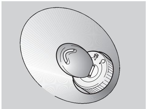
BULBS
Carefully read p. 35 (MAINTENANCE).
Before changing a bulb, position the vehicle on the centre stand and turn the ignition switch to position "8".
Change the bulb wearing clean gloves or using a clean and dry cloth.
Do not leave fingerprints on the bulb, since these may cause its overheating and consequent breakage. If you touch the bulb with bare hands, remove any fingerprint with alcohol, in order to prevent it from blowing frequently.
DO NOT FORCE THE ELECTRIC CA-BLES
Before changing a bulb, check the fuse, see p. 52 (CHANGING THE FUSE).
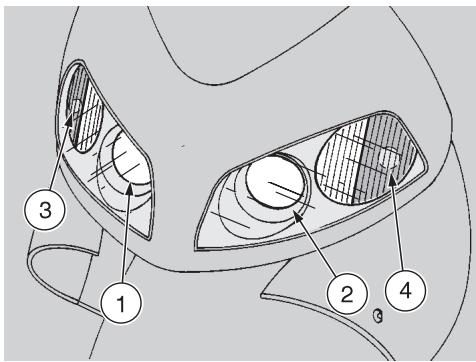
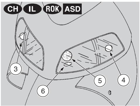
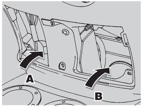
CHANGING THE HEADLIGHT BULBS
Carefully read p. 53 (BULBS).
The headlight contains:
-A right, low beam bulb (1).
- A left, low beam bulb (2).
-A front right direction indicator bulb (3).
-A front left direction indicator bulb (4).
The headlight CH IL ROK ASD contains:
- An upper central, low/high beam bulb (5).
- A lower central, parking light bulb (6).
-A front right direction indicator bulb (3). - A front left direction indicator bulb (4).
To reach the bulbs, proceed as follows:
Remove the front inspection cover, see p. 46 (REMOVING THE FRONT INSPECTION COVER).
Reach the protection elements of the bulbs (1) and (3) from the right side (A).
Reach the protection elements of the bulbs (2) and (4) from the left side (B).
CH IL ROK ASD The bulbs (5) and (6) are provided with a single central protection element (7); to reach it, work on the right side (A) with one hand and on the left side (B) with the other hand.
LOW BEAM BULBS (1) AND (2)
To change the bulbs, proceed as follows:
Manually withdraw the protection element of the bulb that must be replaced.
Rotate the check tang (8) positioned at the back of the bulb socket sideways.
Extract the bulb and replace it with a new one of the same type.
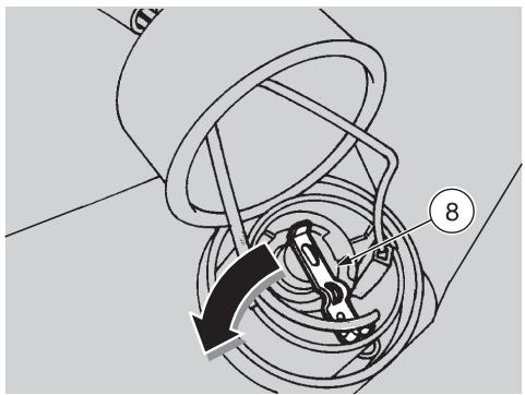
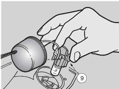
FRONT DIRECTION INDICATOR BULBS (3) AND (4)
To change the bulbs, proceed as follows:
Manually withdraw the protection element of the bulb that must be replaced.
Press the two clips provided on the bulb socket (9) with two fingers, while withdrawing it from its seat at the same time.

Upon reassembly, insert the bulb socket (9) with the clips into a real position and fit it in its seat; and will indicate that the bulb socket is aligned correctly.
Press the bulb moderately, rotate it anticlockwise, extract it and replace it with a new one of the same type.

- Introduce the bulb in the bulb's socket, making sure that the two pins coincide with the relevant bus on the bulb socket.
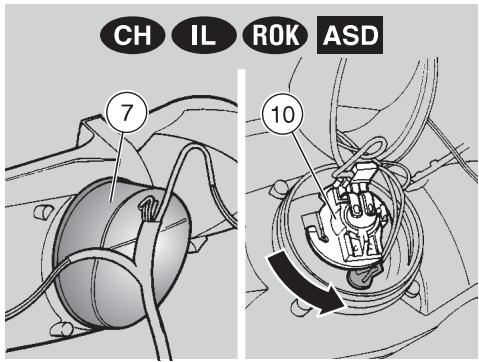

LOW/HIGH BEAM BULB (5)
To change the bulb, proceed as follows:
Manually withdraw the protection element (7)
Rotate the bulb socket (10) anticlockwise and extract it.
Slightly press the bulb (5) and rotate it anticlockwise, extract it and replace it with a new one of the same type.
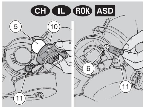

PARKING LIGHT BULB (6)
To change the bulb, proceed as follows:
Manually withdraw the protection element (7).
Rotate the bulb socket (10) anticlockwise and extract it.

Do not pull the electric cables to extract the bulb socket.
Working on the left side (B), grasp the parking light bulb socket (11), pull and remove it from its seat.
Withdraw the parking light bulb (6) and replace it with a new one of the same type.
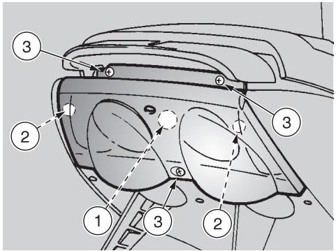
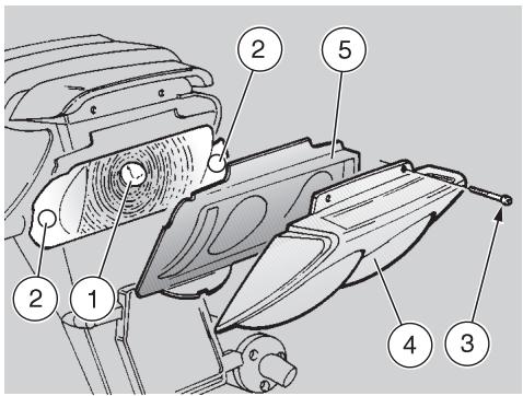
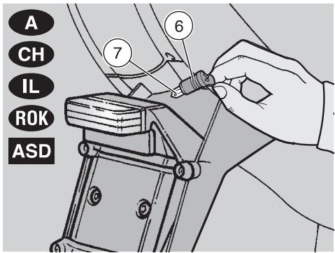
CHANGING THE REAR LIGHT BULB
Carefully read p. 53 (BULBS).
The rear light contains:
A parking light/stoplight bulb (1).
Two rear direction indicator bulbs (2).
To change them:
Support the protection screen (4) and the coloured screen frame (5) to prevent them from falling down and avoid any damage.
Unscrew and remove the three screws (3).
Remove the protection screen (4).
Remove the coloured screen frame (5).
If necessary, the coloured screens can be removed from their frame (5). Slightly push them out
of their seats (from the inside towards the outside) and change them if necessary.
Slightly press the bulb and rotate it anticlockwise.
Remove the bulb from its seat.
Insert the bulb in the socket, making the two bulb pins coincide with the relevant guides on the socket.
Correctly install a new bulb of the same type.
Upon reassembly, position the protection screen (4) and the coloured screen frame (5) correctly in their seats.
Tighten the screw (3) carefully, without exerting too much pressure, in order to avoid damaging the protection screen.
CHANGING THE NUMBER PLATE BULB A CH IL ROK ASD
Carefully read p. 53 (BULBS).
To change the bulb:

Do not pull the electric wires to extract the bulb socket.
Grasp the bulb socket (6), pull it and remove it from its seat.
Withdraw the bulb (7) and replace it with a new one of the same type.


Before transporting the vehicle, it is necessary to empty the fuel
tank and the carburettor completely, making sure that both are completely dry. During transport, the vehicle must be held upright, in its normal use position, to avoid any oil and battery fluid leakage.

DRAINING THE FUEL TANK
Carefully read p. 23 (FUEL).

Risk of fire.
Wait until the engine and the exhaust silencers have comple
tely cooled down.
Fuel vapours are noxious for your health.
Before proceeding, make sure that the room in which you are working is properly ventilated.
Do not inhale fuel vapours.
Do not smoke, nor use free flames.
Do not dispose of fuel in the environment.
Position the vehicle on the centre stand.
Stop the engine and wait until it has cooled down.
Prepare a container with capacity exceeding the fuel quantity present in the tank and put it on the ground on the left side of the vehicle.
Empty the fuel tank by means of a manual pump or a similar system.

After draining the tank, tighten the plug.
To empty the carburettor completely, proceed as follows:
Remove the filter casing, see p. 37 (AIR CLEANER - REMOVAL).
Put the free end of the pipe (1) into a receptacle.
Open the carburettor outlet by loosening the drain screw (2) positioned under the float chamber.
When all the fuel has flowed out of the carburettor:
Tighten the drain screw (2) completely.

Tighten the drain screw (2) with care, to avoid fuel leakages from the carburettor during the refuelling.

Clean the vehicle frequently if it used in particular areas or conditions, such as:
Polluted areas (cities and industrial areas).
- Areas characterized by an high percentage of salinity and humidity (sea areas, hot and humid climates).
Particular conditions (use of salt and anti-ice chemical products on the roads during the winter).
Avoid leaving deposits of industrial and polluting powders, tar spots, dead insects, bird droppings, etc. on the body.
Avoid parking the vehicle under trees, since in some seasons residues, resins, fruits or leaves fall down, which contain substances that may damage the paint.

After the vehicle has been washed, its braking functions could be temporarily impaired, use of the presence of water on the surfaces.
Calculate long braking distances to avoid accidents. Brake repeatedly to restore normal conditions.
To remove dirt and mud from the painted surfaces use a low- pressure water jet; carefully wet the dirty parts, remove mud and filth with a soft car sponge impregnated with a lot of water and shampoo (2÷ 4%) parts of shampoo in water).
Then rinse with plenty of water and dry with chamois leather.
To clean the outer parts of the engine use a degreaser, brushes and wipers.

Polish with silicone wax only after having carefully washed the

Do not wash the vehicle under the sun, especially during the winter, when the body is still warm, if the shampoo dries before being away, it can damage the paint.
Use neither high pressure water/air jets, nor vapour jets on the following parts: wheel hubs, controls on the right and on the left side of the handlebars, brake pump, instruments and indicators, silencer exhaust, glove compartment, ignition switch/steering lock.
Do not use alcohol or solvents to clean the rubber and plastic parts and the saddle: use water and mild soap.
Do not apply protection waxes onto the saddle, in order not to make it too slippery.

LONG PERIODS OF INACTIVITY
After a long period of inactivity of the vehicle some precautions are necessary to avoid any problem.
Further, it is important to carry out the necessary repairs and a general check up before the period of inactivity, since you could forget to carry them out later.
Proceed as follows:
Empty the fuel tank and the carburettor, see p. 57 (DRAINING THE FUEL TANK).
Extract the spark plug and pour a teaspoon (5 - 10~cm^3) of two-stroke engine oil into the cylinder.
Move the ignition switch to position "O", press the start push button "⑧" for a few seconds, to distribute the oil evenly on the cylinder surfaces.
Put back the spark plug.
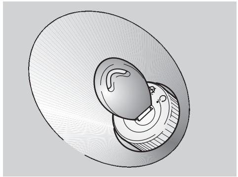
Remove the battery, see p. 50 (REMOVING THE BATTERY) and p. 49 (LONG INACTIVITY OF THE BATTERY).
Wash and dry the vehicle, see p. 58 (CLEANING).
Polish the painted surfaces with wax.
Inflate the tyres, see p. 27 (TYRES).
By means of a suitable support, position the vehicle so that both tyres are raised from the ground.
Place the vehicle in an unheated, not-humid room, away from sunlight, with minimum temperature variations.
Cover the vehicle avoiding the use of plastic or waterproof materials.
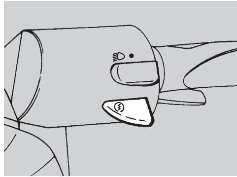
AFTER A PERIOD OF INACTIVITY
Uncover and clean the vehicle, see p. 58 (CLEANING).
Check the electrolyte level in the battery and install it, see p. 51 (CHECKING THE ELECTROLYT E LEVEL) and (INSTALLING THE BATTERY).
Make sure that the fuel drain screw is thoroughly screwed (breather pipe closing index), see p. 57 (DRAINING THE FUEL TANK).
Refuel, see p. 23 (FUEL).
Carry out the preliminary checking operations, see p. 29 (PRELIMINARY CHECKING OPERATIONS).

Have a test ride at moderate speed in a low-traffic area.
TECHNICAL DATA
| DIMENSIONS | Max. length | 1790 mm |
| Max. width | 701.5 mm | |
| Max. height (front part of the fairing included). | 1110 mm | |
| Seat height | 810 mm | |
| Distance between centres | 1260 mm | |
| Min. ground clearance | 140 mm | |
| Weight ready for starting | 106 kg | |
| ENGINE | Type | MINARELLI, 2-stroke with controlled ignition |
| Number of cylinders | 1 | |
| Total displacement | 49.26 cm3 | |
| Bore/stroke | 40 mm / 39.2 mm | |
| Compression ratio | 12.5 ± 0.5:1 | |
| Starting | electric + kick starter | |
| Clutch | centrifugal | |
| Change gear | automatic stepless variator | |
| Cooling | liquid cooled | |
| CAPACITY | Fuel (reserve included) | 11.5 l |
| Fuel reserve | 2±0.5 l | |
| Transmission oil | 110 cm3 | |
| Mixer oil (reserve included) | 1.3 l | |
| Mixer oil reserve | 0.3 l | |
| Coolant | 0.8 l (50% antifreeze + 50% water) | |
| Seats | 1 (2 in the countries where this is allowed) | |
| Vehicle max. load | ||
| (driver + luggage) | 105 kg | |
| (driver+passenger+luggage) | 180 kg (in the countries where this is allowed) |
| TRANSMISSION | Speed change gear | automatic and stepless |
| Primary | V-belt | |
| Ratios | minimum for stepless change: 2.6 maximum for stepless change: 0.862 | |
| Secondary | with gears |
| CARBURETTOR | Model | DELL'ORTO PHBN 12 |
| Choke tube | Ø12 mm | |
| FUEL SUPPLY | Fuel | premium grade petrol (4 Stars UK) according to the DIN 51600 standard, min. O.N. 98 (N.O.R.M.) and 88 (N.O.M.M.) |
| Fuel | unleaded petrol according to the DIN 51607 standard, min. O.N. 95 (N.O.R.M.) and 85 (N.O.M.M.) |
FRAME Type. one-beam, split in two cradles
SUSPENSIONS Front . . . . . . . . . . . . . . . . . . . . . . . . . . . . . . . . . . . . . . . . . . . . . . . . . . . . . . . . . . . . . . . . . . .
Stroke 57 mm
Rear. hydraulic mono-shock absorber
Stroke 90 mm
BRAKES Front . disc brake, 190 mm with hydraulic transmission
Rear. disc brake, 190 mm with hydraulic transmission
WHEELS RIMS. .alloy
Front 3.50 x 13
Rear. 3.50 x 13
TYRES. tubeless
Front 130/60 - 13
Rear. 130/60 - 13
STANDARD INFLATION PRESSURE
Front 180 kPa (1.8 bar)
Rear. 200 kPa (2.0 bar)
INFLATION PRESSURE WITH PASSENGER (where drive with passenger is allowed)
Front 200 kPa (2.0 bar)
Rear. 220 kPa (2.2 bar)
IGNITION
Type CDI
Spark advance 14^± 2^ before T.D.C.
Standard spark plug. NGK R BR8 HS
Spark plug gap. 0.5÷ 0.6 mm
Engine idle rpm 1800 ± 100 rpm
ELECTRIC SYSTEM
Battery. 12 V - 4 Ah
Fuse 7.5 A
Generator (with permanent magnet) 12 V - 85 W
Low beam bulbs 12 V - 15 W
Low/high beam bulb CH IL ROK ASD 12 V - 35/35 W
Front parking light bulbs CH IL ROK ASD 12 V - 3 W
Direction indicator bulbs. 12 V - 10 W
Rear parking light/stoplight bulb. 12 V - 5/21 W
Number plate bulb A CH IL 80k ASD 12 V - 3 W
Low beam warning light. LED
High beam warning light CH IL ROK ASD ...... LED
Direction indicators warning light LED
2 stroke oil reserve warning light LED
Low fuel warning light LED
LUBRICANT CHART
Transmission oil (recommended): F.C., SAE 75W - 90.
As an alternative to the recommended oil, it is possible to use high-quality oils with characteristics in compliance with or superior to the A.P.I. GL4 specifications.
Mixer oil (recommended): GREEN HIT.
Use high-quality oils with characteristics in compliance with or superior to the ISO-L-ETC++, A.P.I. TC++ specifications.
Fork oil (recommended): F.A. 5W or F.A. 20W fork oil.
If you need an oil with intermediate characteristics in comparison with the two recommended products, these can be mixed as indicated below:
SAE 10W F.A. 5W 67% of the volume, + F.A. 20W 33% of the volume.
SAE 15W F.A. 5W 33% of the volume, + F.A. 20W 67% of the volume.
Bearings and other lubrication points (recommended): AUTOGREASE MP.
As an alternative to the recommended product, use high-quality grease for rolling bearings, working temperature range -30^ + 140^ , dripping point 150^ + 230^ , high protection against corrosion, good to water and oxidation resistance.
Protection of the battery poles: neutral grease or vaseline.
Spray grease for chains (recommended): CHAIN SPRAY.
Brake fluid (recommended): F.F., DOT 5 (DOT 4 compatible).

Use new brake fluid only.
Engine coolant (recommended) ≈ ECOBLU -40°C.

Use only antifreeze and anticorrosive without nitrite, ensuring protection at -35^ at least.
| APRILIA s.p.a. | via G. Galilei, 1 - 30033 Noale (VE) Italy Tel. +39(0)41 5829111 - Fax +39(0)41 441054 - Call FREE on 167-565220 (Italy only) |
| APRILIA FRANCE S.A. | Z.A. Central Parc - 255 BLD Robert Ballanger B.P. 77- 93421 Villepinte (F) - Tel. (0) 149634747 - Fax (0) 149638750 |
| A & G MOTORRAD VERTRIEB GmbH | Am Seestern 3 D-40547 Düsseldorf (D) Tel. (211) 59018-00 - Fax (211) 5901819 |
| APRILIA HISPANIA S.A. | Calle Alcorcon 19 - 28850 Torrejon de Ardoz - Madrid (E) Tel. (91) 6778083 - Fax (91) 6778577 |
| APRILIA NEDERLAND | Nikkelstraat 1 - 4823 AE Breda (NL) Tel. (076) 5431640 - Fax (076) 5431649 |
| APRILIA MOTO U.K. LTD. | Dunragit - Stranraer - Wigtownshire DG9 8PN - Scotland (UK) Tel. (01581) 400660 - Fax (01581) 400661 |
| GINZINGER IMPORT GmbH & CO | Frankenburgerstrasse 19 - 4910 Ried im Innkreis (A) Tel. (7752) 88077 - Fax (7752) 70684 |
| MILFA IMPORTAZão EXPORTAZão LDA | Av. da Republica 692 - 4450 Matosinhos (P) Tel. (2) 9382450 - Fax (2) 9371305 |
| TUONTI NAKKILA OY | Harjavallante, 7 - 29250 Nakkila (SF) Puh. (02) 5352500 - Fax (02) 5372793 |
| n.v./s.a.RAD | Landegemstraat 4 - Industrieterrein - 9031 Drongen (B) Tel. (09) 2824929 - Fax (09) 2829433 |
| MOBILITY S.A. | av. Messogion 191 - 11525 Athens (GR) Tel. (1) 6728705-6728715 - Fax (1) 6728727 |
| MOBILITY A.E. | Λ. Μεσογειων 191 - 115-25 Αθηνα - Ελλαδα Tηλ. (1) 6728705-6728715 - Φαξ: (1) 6728727 |
aprilia
ASK FOR Genuine SPARE PARTS ONLY
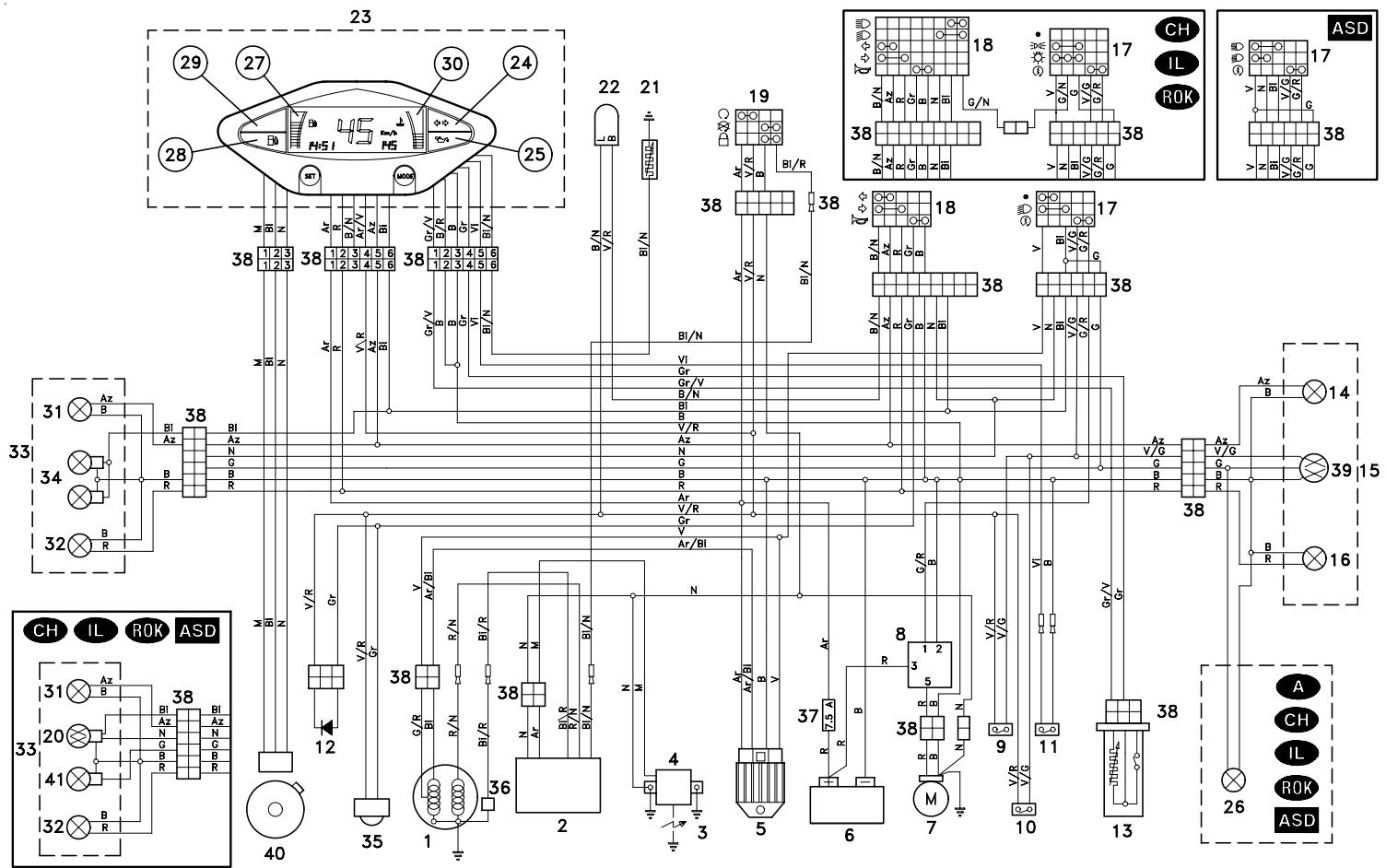
WIRING DIAGRAM Area 51
WIRING DIAGRAM KEY Area 51
1) Generator
2) CDI
3) Spark plug
4) HT coil
5) Voltage regulator
6) Battery
7) Starter
8) Start relay
9) Front stoplight switch
10) Rear stoplight switch
11) 2 stroke oil reserve switch
12) Diode
13) Fuel level sensor
14) Rear right direction indicator
15) Rear light
16) Rear left direction indicator
17) Right dimmer switch
18) Left dimmer switch
19) Ignition switch/steering lock
20) Low/high beam bulb
21) Coolant thermistor
22) Blinking
23) Dashboard
24) Direction indicator warning light
25) 2 stroke oil reserve warning light
26) Number plate light
27) Fuel level indicator
28) Low fuel warning light
29) Low beam warning light
29) High beam warning light CH IL ROK ASD
30) Coolant temperature indicator
31) Front right direction indicator
32) Front left direction indicator
33) Front parking light
34) Low beam bulbs
35) Horn
36) Pick up
37) Fuse
38) Multiple connectors
39) Rear parking light / stoplight bulb
40) Speed sensor
41) Front parking light
CABLE COLOURS
Ar Orange
Az Light blue
B Blue
Bi White
G Yellow
Gr Grey
M Brown
N Black
Red
V Green
Vi Violet
aprilia s.p.a. wishes to thank its customers for the purchase of this vehicle.
- Do not dispose of oil, fuel, polluting substances and components in the environment.
- Do not keep the engine running if it isn't necessary.
- Avoid disturbing noises.
- Respect nature.
- FOREWORD
- IMPORTANT:
- VERSION:
- TABLE OF CONTENTS
- aprilia
- BASIC SAFETY RULES
- CLOTHING
- ACCESSORIES
- LOAD
- KEY
- ARRANGEMENT OF THE INSTRUMENTS
- INSTRUMENTS AND INDICATORS
- PROGRAMMING PUSH BUTTONS
- SWITCHING FROM KILOMETRES (km/h) TO MILES (MPH) FOR THE UK ONLY
- SETTING THE CLOCK (HOURS AND MINUTES)
- CONTROLS ON THE LEFT SIDE OF THE HANDLEBAR
- 1) LIGHT SWITCH (ED - ●)
- 1a) LIGHT SWITCH (C - - - - ) CH 1L ROK
- 2) START PUSH BUTTON (③)
- IGNITION SWITCH
- STEERING LOCK
- OPERATION
- Turn the key and steer the handlebar at the same time.
- AUXILIARY EQUIPMENT
- UNLOCKING/LOCKING THE SADDLE
- CRASH HELMET / GLOVE COMPARTMENT
- ANTI-THEFT HOOK
- TOOL KIT
- REAR MUDGUARD EXTENSION
- The rear mudguard extension (4)
- FUEL
- STROKE OIL TANK
- BRAKE FLUID · recommendations
- KEEP AWAY FROM CHILDREN
- DISC BRAKES
- CHECKING
- COOLANT
- CHECKING AND TOPPING UP
- TOPPING UP
- TYRES
- INFLATION PRESSURE
- MINIMUM TREAD深度LIMIT
- AUTOMATIC LIGHT SWITCHING VERSION ASD
- CATALYTIC SILENCER
- INSTRUCTIONS FOR USE
- STARTING
- ELECTRIC STARTING
- KICK START
- Do not push down the kick starter with the engine on.
- STARTING AFTER A LONG PERIOD OF INACTIVITY
- DEPARTURE AND DRIVE
- RUNNING-IN
- 0-300 km
- 300-500 km
- STOPPING
- PARKING
- POSITIONING THE VEHICLE ON THE STAND
- CENTRE STAND
- SUGGESTIONS TO PREVENT THEFT
- MAINTENANCE
- IDENTIFICATION DATA
- ENGINE NUMBER
- FRAME NUMBER
- AIR CLEANER
- REMOVAL
- CLEANING THE AIR FILTER
- CHECKING THE TRANSMISSION OIL LEVEL
- CHANGING THE TRANSMISSION OIL
- DO NOT DISPOSE OF THE TRANSMISSION OIL IN THE ENVIRONMENT.
- Proceed as follows:
- FRONT WHEEL
- DISASSEMBLY
- REASSEMBLY
- REAR WHEEL
- Carefully read p. 35 (MAINTENANCE).
- To unscrew the wheel nut (3), it is necessary to lock the rotation of the wheel.
- Upon reassembly, uniformly apply a moderate quantity of grease on the wheel pin, see p. 64 (LUBRICANT CHART) and replace the wheel nut (special type) with a new one.
- REMOVING THE FRONT AND REAR BRAKE CALIPERS
- CHECKING THE STEERING
- THE ENGINE FULCRUM AXIS
- REMOVING THE EXHAUST SILENCER
- REMOVING THE REAR-VIEW MIRROR
- REMOVING THE FRONT INSPECTION COVER
- REMOVING THE RIGHT AND LEFT INSPECTION COVERS
- REMOVING THE REAR INSPECTION COVER
- IDLING ADJUSTMENT
- ADJUSTING
- THE ACCELERATOR CONTROL
- SPARK PLUG
- BATTERY
- LONG INACTIVITY OF THE BATTERY
- CHECKING AND CLEANING THE TERMINALS
- REMOVING THE BATTERY
- CHECKING THE ELECTROLYT E LEVEL
- Top up with distilled water only. Do not exceed the "MAX" mark, since the electrolyte level increases during the recharge.
- RECHARGING THE BATTERY
- Reinstall the battery only 5-10 minutes after disconnecting the recharge equipment, since the battery keeps sending out extremely inflammable hydrogen gas for a short lapse of time.
- INSTALLING THE BATTERY
- Always connect the battery breather pipe, to prevent the sulphuric acid vapours from corroding the electric system, painted parts, rubber elements or gaskets when they exit the breather pipe itself.
- CHANGING THE FUSE
- For the checking, proceed as follows:
- ARRANGEMENT OF THE FUSE
- A fuse from the battery to:
- ADJUSTING THE VERTICAL HEADLIGHT BEAM
- BULBS
- CHANGING THE HEADLIGHT BULBS
- Carefully read p. 53 (BULBS).
- To reach the bulbs, proceed as follows:
- LOW BEAM BULBS (1) AND (2)
- To change the bulbs, proceed as follows:
- CHANGING THE REAR LIGHT BULB
- CHANGING THE NUMBER PLATE BULB A CH IL ROK ASD
- DRAINING THE FUEL TANK
- LONG PERIODS OF INACTIVITY
- AFTER A PERIOD OF INACTIVITY
- TECHNICAL DATA
- IGNITION
- ELECTRIC SYSTEM
- LUBRICANT CHART
- ASK FOR Genuine SPARE PARTS ONLY
- WIRING DIAGRAM KEY Area 51
- CABLE COLOURS
Brand : APRILIA
Model : AREA 51
Category : Scooter