
B1RKM15001 - Air conditioner BOSCH - Free user manual and instructions
Find the device manual for free B1RKM15001 BOSCH in PDF.


| Brand | Bosch |
| Model | B1RKM15001 |
| Product type | Split system air conditioner |
| Indoor unit dimensions (WxHxD) | 80 x 30 x 20 cm |
| Outdoor unit dimensions (WxHxD) | 70 x 50 x 30 cm |
| Indoor unit weight | 10 kg |
| Outdoor unit weight | 30 kg |
| Power supply | 230 V / 50 Hz |
| Cooling capacity | 2.5 kW |
| Heating capacity | 2.8 kW (reversible mode) |
| Main functions | Cooling, heating, dehumidification, ventilation, 24h programming, remote control |
| Filter | Washable and antibacterial air filter |
| Energy class (cooling) | A++ |
| Routine maintenance | Clean the filter every 2 weeks; check the condenser fins |
| Safety | Overheat protection, automatic shutdown in case of fault, child safety (remote control lock) |
| Spare parts available | Yes, contact Bosch after-sales service |
| General information | Refrigerant R32; indoor sound level 25 dB(A) |
Frequently Asked Questions - B1RKM15001 BOSCH
User questions about B1RKM15001 BOSCH
0 question about this device. Answer the ones you know or ask your own.
Ask a new question about this device
Download the instructions for your Air conditioner in PDF format for free! Find your manual B1RKM15001 - BOSCH and take your electronic device back in hand. On this page are published all the documents necessary for the use of your device. B1RKM15001 by BOSCH.
USER MANUAL B1RKM15001 BOSCH
B1 RKM 15001
GB Instructions for Use
FR Mode d'emploi
Household Appliances



Air purification

Disposal of packaging 22
Disposal of your old appliance ....22
Before connecting your new appliance ....22
Your new appliance
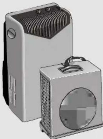
Description of your appliance ....23
Control panel 24
Accessories....24
Requirements for use ....25
Transportation requirements....26
Preparations
Positioning of the outdoor unit ....27
Indoor/outdoor unit communication....28
Separating the flexible duct from the indoor unit ...29
Connecting the flexible duct to the indoor unit .....31
Turning the appliance on
Cooling and Dehumidification ....32
Only dehumidification....33
Air purification ....33
Cleaning and Maintenance....34
Technical service / Warranty ....35
Things that can save you from making unnecessary phone calls ....36
Technical information ....37
Important Observations
Disposal of packaging
Respect the environment when disposing of the material your appliance comes packed in. Our products are all carefully packed for transportation purposes. The packaging is designed to not harm the environment. All the materials used in the production of this packaging are environmentally friendly or can be re-used. Recycling the material your appliance comes packed in helps contribute to the conservation of raw materials and reduces the amount of waste produced in the world. It may be possible to return packaging to the establishment that supplied you with your appliance. Contact them for more information.
Disposal of your old appliance
Unplug your old appliance from the mains electricity supply and cut the power cable. Appliances of this kind contain refrigerants which need to be disposed of in accordance with current regulations. Do not dispose of your old appliance yourself. Get in touch with your local council or other competent body for information about how best to dispose of it.
Before connecting your new appliance
Read the instructions book before using your appliance for the first time. It contains important information, not only concerning use, but maintenance and personal safety as well. Keep this instructions book. It may be useful for later owners. Do not turn a damaged appliance on. Your appliance must be assembled and connected in accordance with the assembly instructions and current regulations. If these instructions are not observed, you run the risk of losing your warranty. All our appliances are made in accordance with present-day safety regulations. Only technicians instructed in these matters are authorised to repair them. Your safety is at stake. Make sure that the drainage plugs are properly inserted. They may have come lose during transportation, Fig. 1.

Your new appliance
Description of your appliance
Indoor Unit
Main filter
Condensed water drainage pipe

Purifying filters
Air-conditioning appliance
Air-intake grille
Wire cavity
Plugged nozzle to drain condensed water Characteristics plate
Outdoor unit
Plugged nozzle to drain water produced by condensation in "Dehumidification" mode
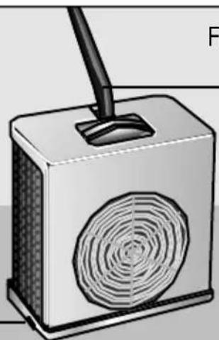
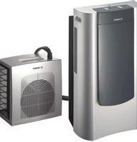
Flexible duct to connect indoor and outdoor units
Control panel

| Maximum air purification |  | Appliance off |
| Maximum temperature control | ||
| Silent air purification | Silent temperature control | |
| Dehumidification |
Accessories

Requirements for Use
Requirements for use
☐ This appliance must be connected to a 220/240 V 50 Hz mains electricity supply using an earthed plug. ☐ It must be protected with a 16 A slow-action fuse. ☐ Should an extension lead be needed, this lead must be at least 1.5 mm² per terminal thick, no more than 25 m long, and earthed. ☐ There is a cavity at the back of the appliance for the mains electricity supply connection wire. ☐ Do not allow water to enter the appliance. ☐ Do not block the air inlets or outlets on your appliance, especially when used for heating.
Should the mains electricity supply wire be damaged in any way, it must only be replaced with a wire of similar characteristics. Get in touch with the manufacturer, after-sales service, or a similarly qualified person.
Warning!
If the appliance is turned off and then turned back on again, there is a 3-minute interval before the compressor starts up again. This interval is necessary in order for the appliance to work properly.
Transportation requirements
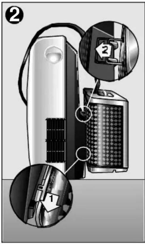
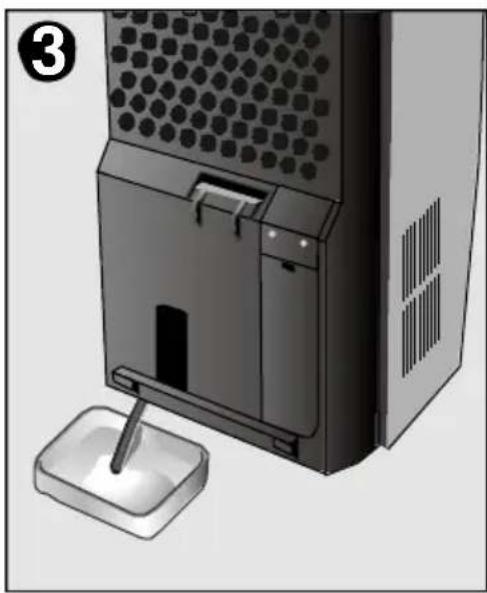
☐ The indoor appliance is mounted on castors to facilitate transportation. To transport the outdoor appliance together with the indoor appliance, hang the outdoor appliance in the park position on the indoor appliance - the appliance can then be moved without difficulty, Fig. 2. ☐ There are castors fitted on your appliance to make moving it easier. If it is necessary to tilt your appliance in order to move it, then the internal water tank must be drained first. To do this, connect the drainage pipe to the stopcock at the bottom of the appliance, Fig. 3. ☐ If only the outdoor appliance is transported, first pull the stopper out of the outdoor appliance, tilt the outdoor appliance slightly, and pour out the remaining water.
Warning!
Be particularly careful when transporting this unit. There is a water drainage pipe on the bottom of the appliance which may break if knocked.
Preparations
Positioning of the outdoor unit
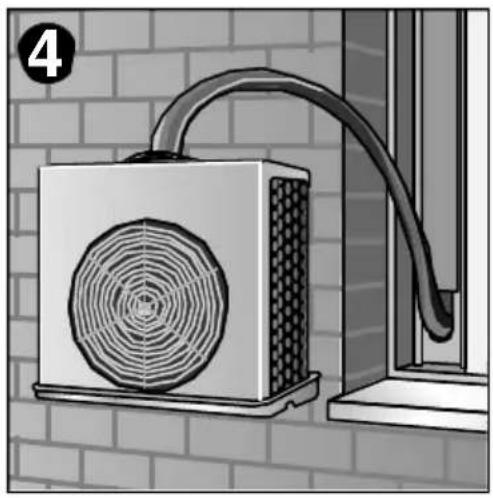
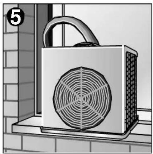

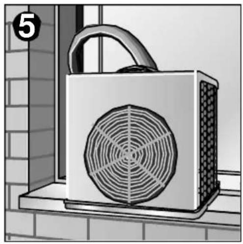
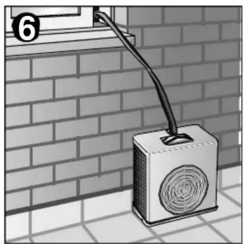
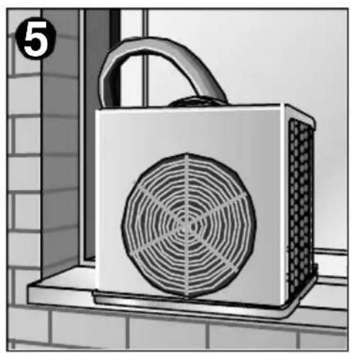
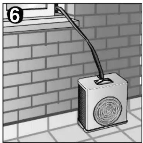
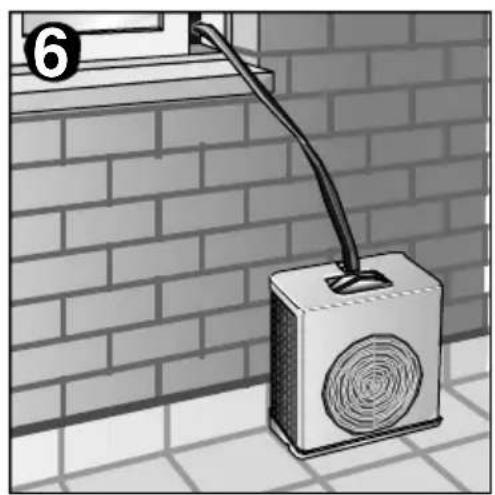
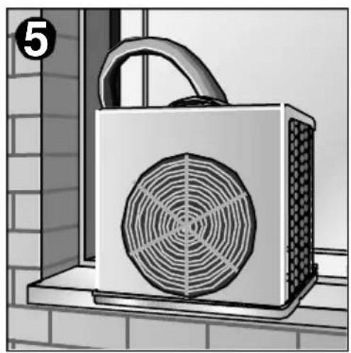
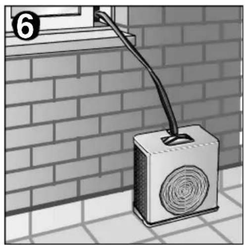
The outdoor unit can be set in any of the three positions shown in figures 4, 5 and 6 as desired depending on space conditions. Remember that the outdoor unit must be placed on a horizontal surface. Use the Support Plate accessory in order to hang the outdoor unit from the hook it comes supplied with.
Warning!
Make sure that the appliance is hung in a horizontal position, else the lower tray may shed water. To do so, adjust the rear bar on the outdoor unit. For safety reasons, never allow the outdoor unit to hang solely from the duct that joins it with the indoor unit. Do not set the outdoor unit higher than permitted. Observe the minimum permitted distances between the appliance and other objects. See figure 7. Do not impede or twist the flexible duct that joins the two units.

Indoor/outdoor unit communication

The two units are joined by a flexible duct which affords a number of installation options:
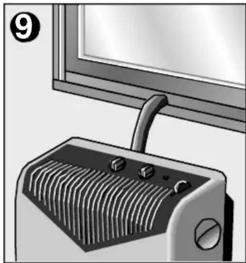
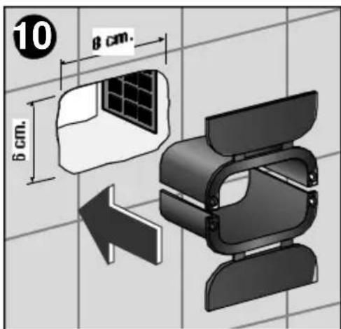
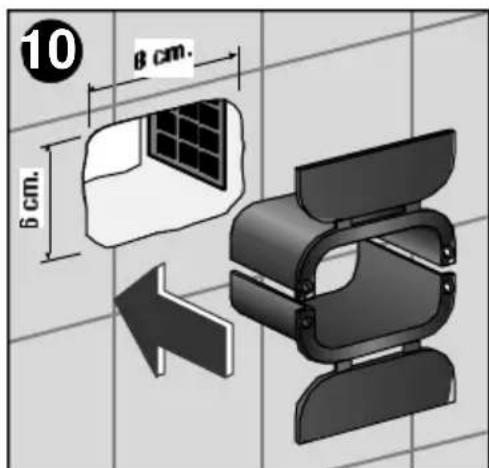
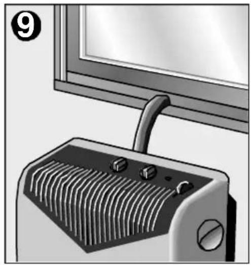
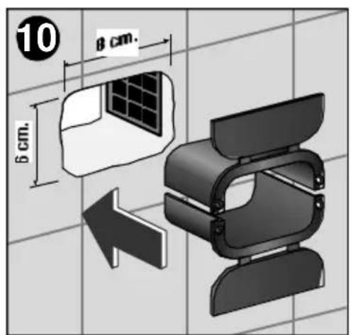
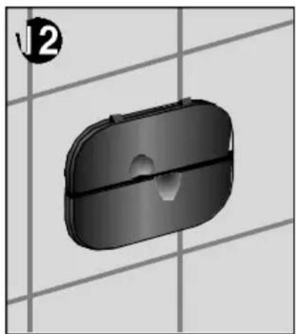
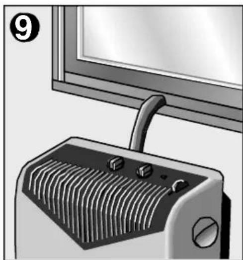
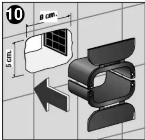
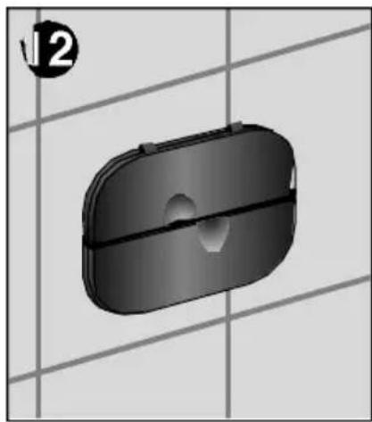
Pass the duct through a door or window left ajar, Fig. 8. Make a 4 x 2-cm hole in a door or window frame to pass the duct through, thereby avoiding having to leave the door or window open, Fig. 9. Make a hole in the wall and fit the Protective sleeve accessory, Fig. 10, 11 and 12.
The covers on the accessory can be closed when the appliance is not in use or not required, thereby sealing the hole in the wall, Fig. 12.



Separating the flexible duct from the indoor unit
Disconnecting the flexible duct
To pass the duct through a window frame or wall, it must first be disconnected from the indoor unit. On certain models, this can be done via fast connection, proceeding as follows:
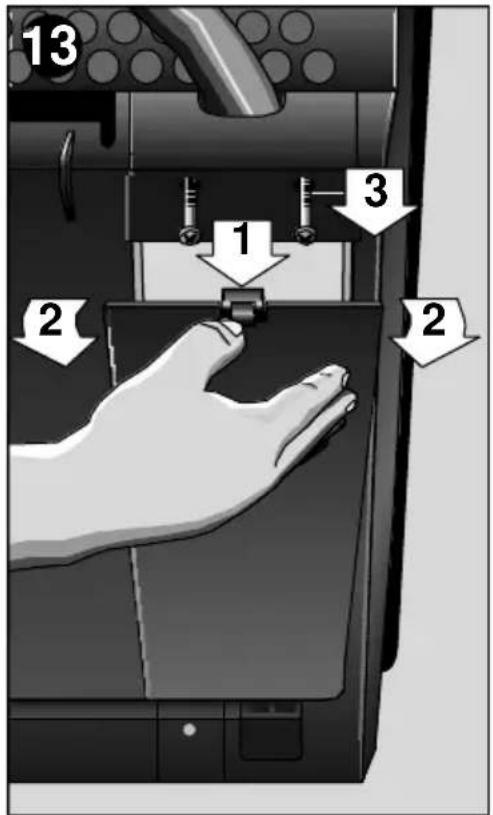
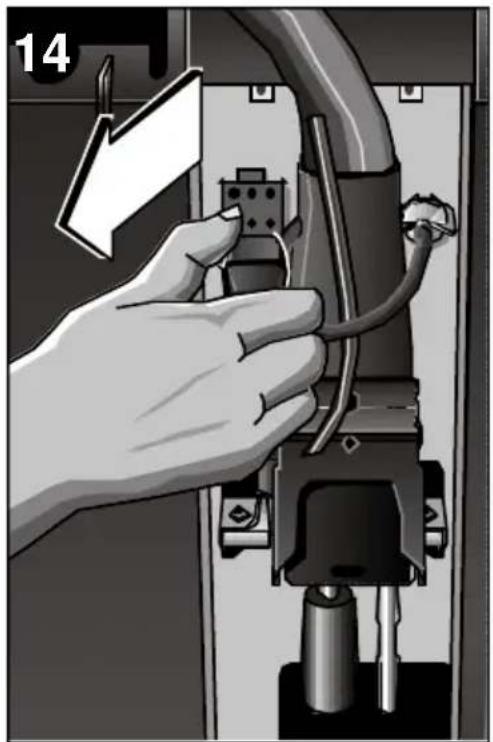
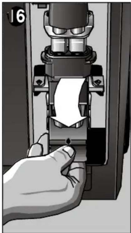
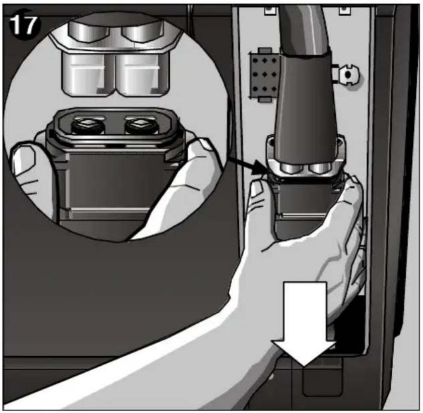
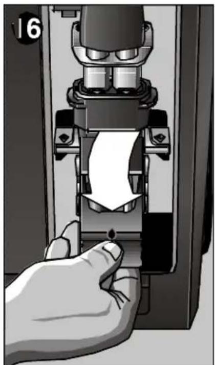
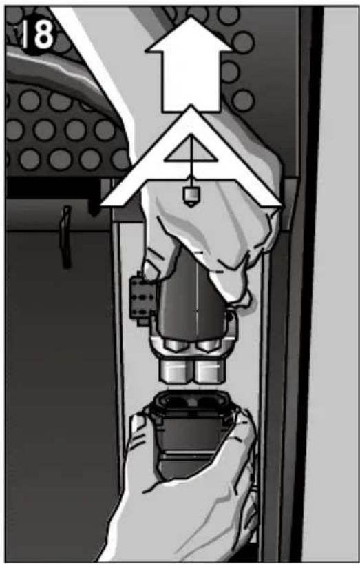
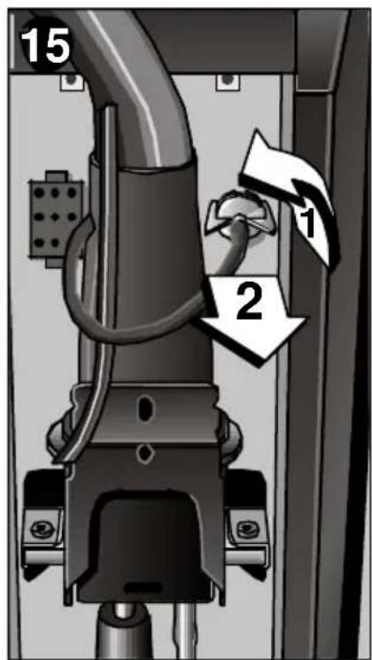
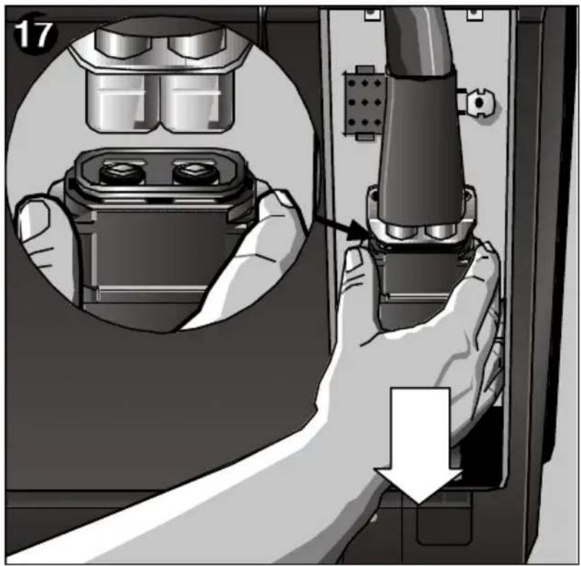
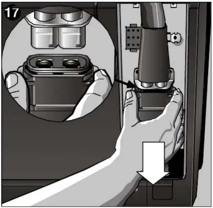
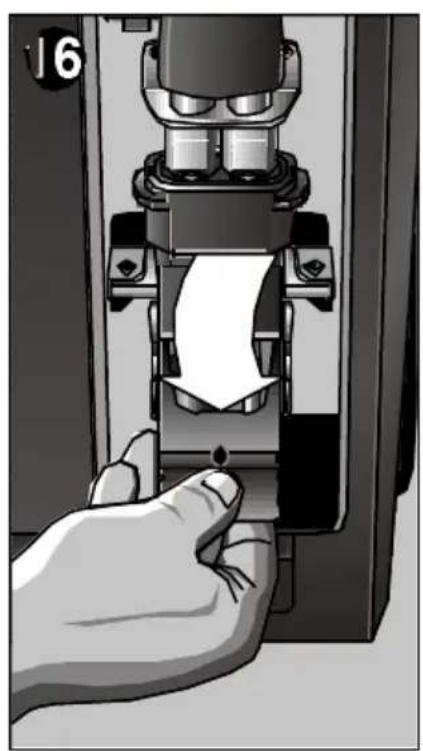
Unplug the appliance from the mains electricity supply. Remove the lower cover from the connection area and the screws from the upper cover. The flexible duct connection area can now be seen, Fig. 13. Remove the electrical connection by squeezing the upper and lower tabs on the plug. See Fig. 14. Disassemble the condensed water drainage pipe by turning it 90° in an anti-clockwise direction and extracting, Fig. 15. Push the fast connection lever down, Fig. 16. Push the metal coupling fixture down, Fig. 17, and pull the duct upwards at the same time, Fig. 18.


Connecting the flexible duct to the indoor unit
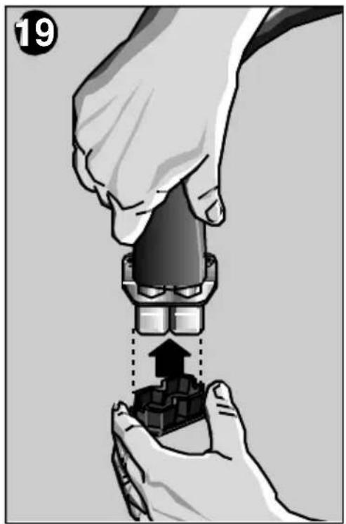

Reconnect the flexible duct to the indoor unit by following the inverse process to that just described.
Warning!
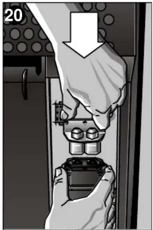
The fast connection can only be mounted in one position, see Figure 18. It must only be inserted in its housing in a vertical position. Exerting a little force, pull up the lever until it is vertical. Only then is the hose connected correctly. Should the indoor and outdoor units be disconnected for a lengthy period of time, protect the free end of the flexible duct using the protective cap (See Accessories and Fig. 19) supplied to prevent dust and dirt from entering and fit the protective copper cover over the valves, Fig. 20. You are recommended not to leave the duct disconnected from the indoor unit for more than 24 hours. Never operate the indoor appliance without the outdoor appliance.
Turning the appliance on
Cooling and Dehumidification
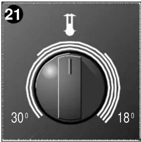

Plug the appliance into the mains electricity supply. Select either the "Maximum cooling" or the "Silent cooling" option. Set the thermostat to the desired temperature, Fig. 21. The appliance cools and dehumidifies the air in the room at the same time in order to produce pleasant air conditions. Should the appliance turn itself off by effect of the thermostat, it will come back on again when room temperature rises 2 or 3°C. The water produced during this process by condensation is led outside and released from the condenser by evaporation.
If the red warning light comes on:
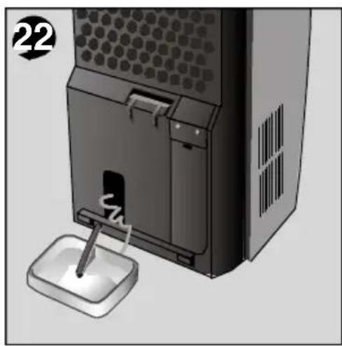
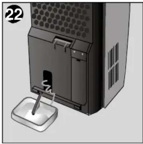
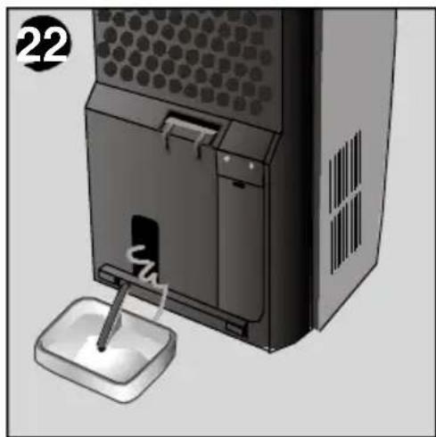
Condensed water has unduly accumulated in the tank on the indoor unit. Condensed water is emptied using the flexible drainage pipe, which is coupled onto the water drainage nozzle on the bottom of the appliance, Fig. 22. Make sure that the flexible duct which joins the two units has not been squashed or been trapped in any way. The difference in height between the two units should not exceed 1.5 m. Fig. 7.
Only dehumidification

Air purification

Set the function at this setting, the appliance will only reduce the humidity present in the atmosphere, without affecting the temperature. The appliance is capable of extracting up to 60 litres of water a day from the air depending on atmospheric conditions.
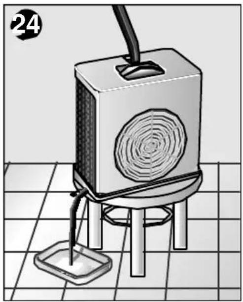
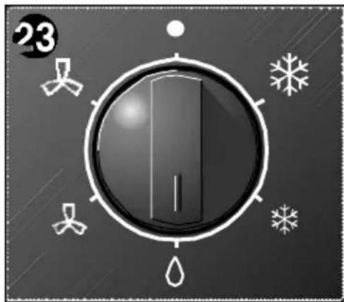
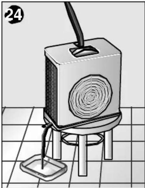
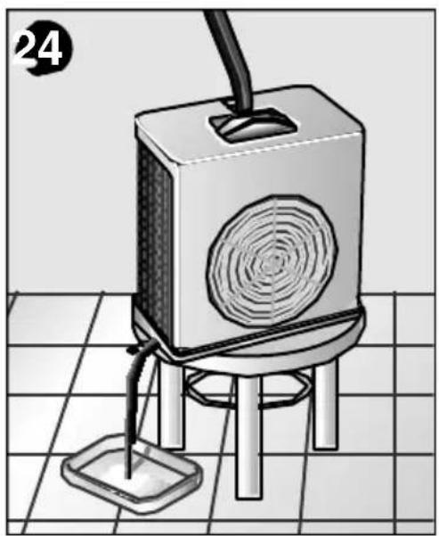
Release the water from the outdoor unit by removing the plug from the lower tray. Move the outdoor unit to the room that you wish to dehumidify. Connect the flexible water drainage pipe to the drainage nozzle on the outdoor unit and collect the water produced by condensation in a suitable receptacle, Fig. 24. Select the "Dehumidification" function. Fig. 23.
Warning!
When you change back to the "Cooling" function, put the plug back into the drainage nozzle on the outdoor unit. Should you fail to do so, the appliance will shed water produced by condensation during the cooling process.
Always remember that in order for the dehumidification function to work properly, ambient temperature must be at least 18°C.
This function circulates the air inside the room passing it through a set of purifying filters in so doing.
The appliance comes with a main filter with a double active purifying filter. Fig. 26. This special filter is for:
- Smells and smoke.
- Pollen, bacteria and dust.
Select between maximum and lower fan speed with the function selector switch, Fig. 25.
We recommend you leave the optional filters in position regardless of the desired function setting. The appliance purifies the air more efficiently in this way.
Cleaning and Maintenance
Cleaning

Prior to use at change of season
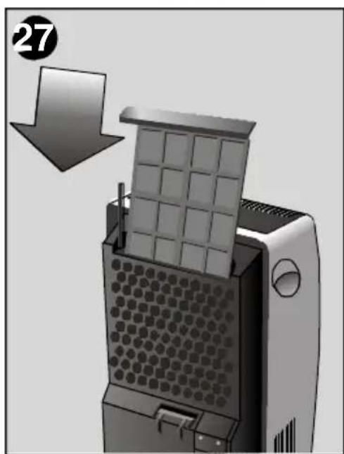
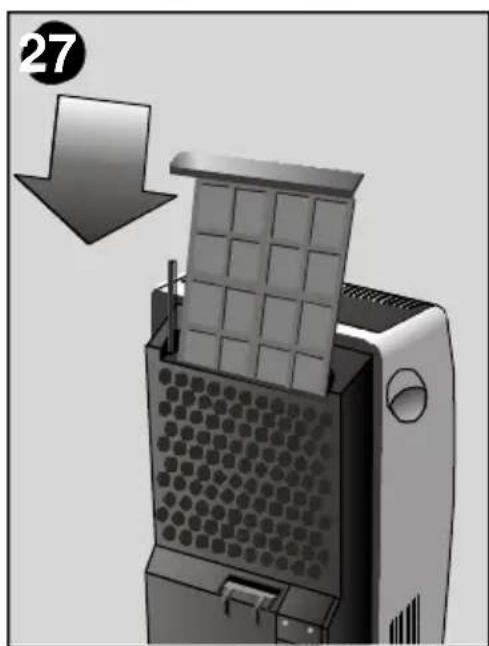
The indoor unit features a main filter, which must be cleaned after prolonged operation. Flush under running water, allow to dry and re-install. The set of additional purifying filters, reference B1 RKZ 15013, must be replaced with a new set every year in order to work efficiently. Contact your supplier. The filters must be fitted as shown in figures 26 and 27. The appliance can be cleaned with a cloth or sponge, warm water and mild detergent. Never use hot water (more than 40°C), bleach, petrol-based products, acids or brushes when cleaning your appliance. Prevent water entering the appliance. Do not clean your appliance with a hose.
Clean the air filter and then the cover and grille if required.
Technical Service / Warranty
Technical service
Should your appliance fail to work properly and all the instructions for use and installation (especially the section headed "Requirements....") have been carefully observed, then remember that our Technical Service Network is at your full disposal.
When contacting the Technical Service, quote the model code (E-NR) and the appliance's factory number (FD). This information can be found on characteristics plate.
Warranty
The conditions of warranty depend on the relevant Supplier in a particular country. Contact the establishment where you purchased your appliance for more information and quote the appliance model and factory number. The receipt of purchase for the appliance must be produced prior to any work carried out under warranty.
Things that can save you from making unnecessary phone calls
What to do if ...
The suggestions below will help you to correct minor faults for yourself and save you calls to Technical Services.
If, after checking through these possibilities, the problem remains unsolved, contact our specialised technical service.
... the appliance doesn't work ...
☐ Make sure that the appliance is plugged in properly. ☐ Make sure that there is power in the mains electricity supply and all the fuses are in working order. ☐ Set the thermostat to a lower temperature, i.e. rotate in a clockwise direction.
... the appliance doesn't work and the safety pilot light comes on ...
☐ Check that the connection hose is not restricted - it must not be crushed. ☐ The outdoor unit should not be positioned or hung more than 1.5 m above the indoor unit. ☐ Place the indoor unit on a flat surface. If the light does not go out, empty the internal water tank. (See instructions in Transport Conditions).
... the appliance operates for a while and then switches off ...
☐ Check whether the air inlet or air outlet is blocked. ☐ Should the outdoor temperature rise above 43°C, the appliance will turn itself off for a short period of time after which it will then turn itself back on again. Should the temperature in or outside of the room fall below 20°C, the appliance will turn itself off temporarily in order to prevent frost or ice from forming on the evaporator. ☐ Make sure that the fast connection is fitted properly, (only on models which include this feature).
... the appliance fails to cool the air properly ...
☐ Ensure that the window or the door is open as little as possible. This is especially important if the window or door has to be opened slightly for the connection hose.
☐ Check that the connection hose is not restricted - it must not be crushed.
... the appliance makes a lot of noise ...
☐ Check that the air inlet and outlet are not blocked.
☐ If you hear a cyclical water noise, the condensate pump is pumping the water outside.
... the appliance is switched on but the compressor is not running...
☐ The ambient temperature must be above 20° C for the appliance to operate in dehumification and cooling mode.
... the outdoor unit is dripping ...
☐ Check that the outdoor unit has been positioned or hung horizontally.
☐ Check that the stopper has been inserted correctly.
Warning!
Any other breakdown or repair should be carried out by a specialised technician. In such cases, contact the authorised dealer, the customer attention service or the Technical Services Dept.
Technical Information
Technical information
Consumption at maximum power .....1.500W
Fuse....16 A
Cooling capacity * 4.250W
Cooling and dehumidification modes:
Indoor temperature: .... min. +20°C/ max. +32°C
Outdoor temperature: .....min. +20°C/ max. +43°C
* Ashrae 128
Index
Important notes
Disposal of packaging ....39
Transport conditions ....43
Preparations
Transport conditions





Apparatus selector switch
Maximum cooling
Quieter cooling
Accessories








Purifying filters













Preparations




Air purification

- AIR PURIFICATION
- YOUR NEW APPLIANCE
- PREPARATIONS
- TURNING THE APPLIANCE ON
- IMPORTANT OBSERVATIONS
- DISPOSAL OF PACKAGING
- DISPOSAL OF YOUR OLD APPLIANCE
- BEFORE CONNECTING YOUR NEW APPLIANCE
- DESCRIPTION OF YOUR APPLIANCE
- INDOOR UNIT
- OUTDOOR UNIT
- CONTROL PANEL
- ACCESSORIES
- REQUIREMENTS FOR USE
- WARNING
- TRANSPORTATION REQUIREMENTS
- POSITIONING OF THE OUTDOOR UNIT
- INDOOR/OUTDOOR UNIT COMMUNICATION
- SEPARATING THE FLEXIBLE DUCT FROM THE INDOOR UNIT
- DISCONNECTING THE FLEXIBLE DUCT
- CONNECTING THE FLEXIBLE DUCT TO THE INDOOR UNIT
- COOLING AND DEHUMIDIFICATION
- IF THE RED WARNING LIGHT COMES ON
- ONLY DEHUMIDIFICATION
- CLEANING AND MAINTENANCE
- CLEANING
- TECHNICAL SERVICE / WARRANTY
- TECHNICAL SERVICE
- WARRANTY
- THINGS THAT CAN SAVE YOU FROM MAKING UNNECESSARY PHONE CALLS
- WHAT TO DO IF
- TECHNICAL INFORMATION
- COOLING AND DEHUMIDIFICATION MODES
- INDEX
- IMPORTANT NOTES
- TRANSPORT CONDITIONS
Brand : BOSCH
Model : B1RKM15001
Category : Air conditioner