
MCC-500MD - Video camera SONY - Free user manual and instructions
Find the device manual for free MCC-500MD SONY in PDF.
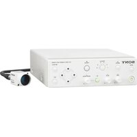


| Product type | Digital video camera |
| Brand | Sony |
| Model | MCC-500MD |
| Sensor | CMOS 1/2.8 inch |
| Maximum resolution | 1920 x 1080 pixels (Full HD) |
| Optical zoom | 20x |
| Image stabilization | Optical |
| Recording format | AVCHD, MP4 |
| Storage media | SD/SDHC/SDXC memory card |
| Screen | 3-inch swivel LCD |
| Dimensions (L x H x D) | 200 x 150 x 100 mm |
| Weight | 1.5 kg (with battery) |
| Power supply | AC adapter or rechargeable Li-Ion battery |
| Battery life | Approximately 2 hours |
| Connectivity | HDMI, USB 2.0, microphone input |
| Maintenance and cleaning | Clean with a soft dry cloth. Avoid moisture and abrasive products. |
| Safety | Do not expose to water, do not open the casing, use only recommended accessories. |
| Spare parts and repairability | Contact Sony after-sales service for repairs and original parts. |
| General information | User manual available for download in PDF format at notice-facile.com. |
Frequently Asked Questions - MCC-500MD SONY
User questions about MCC-500MD SONY
0 question about this device. Answer the ones you know or ask your own.
Ask a new question about this device
Download the instructions for your Video camera in PDF format for free! Find your manual MCC-500MD - SONY and take your electronic device back in hand. On this page are published all the documents necessary for the use of your device. MCC-500MD by SONY.
USER MANUAL MCC-500MD SONY
© 2014 Sony Corporation

This manual is printed on recycled paper.
Printed on recycled paper.
For inquiries, contact:
To reduce the risk of fire or electric shock, do not expose this apparatus to rain or moisture.
To avoid electrical shock, do not open the cabinet. Refer servicing to qualified personnel only.
No modification of this equipment is allowed.
WARNING
THIS APPARATUS MUST BE EARTHED.
WARNING
This unit has no power switch.
To disconnect the main power, unplug the power plug.
When installing the unit, incorporate a readily accessible disconnect device in the fixed wiring, or connect the power plug to an easily accessible socket-outlet near the unit.
Do not position the ME equipment where it is difficult to unplug the power plug.
If a fault should occur during operation of the unit, operate the disconnect device to switch the power supply off, or unplug the power plug.
Do not install the appliance in a confined space, such as a bookcase or built-in cabinet.
CAUTION
The apparatus shall not be exposed to dripping or splashing. No objects filled with liquids, such as vases, shall be placed on the apparatus.
Symbols on the products

General warning sign
Follow the warnings in the Instructions for use for parts of the unit on which this mark appears. NOTE: Background color: Yellow
Triangular band: Black Symbol: Black

Consult the Instructions for use
Follow the directions in the Instructions for use for parts of the unit on which this mark appears.

This symbol indicates the manufacturer, and appears next to the manufacturer's name and address.

This symbol indicates the European Community representative, and appears next to the European Community representative's name and address.

This symbol indicates the equipotential terminal which brings the various parts of a system to the same potential.
For the customers in the U.S.A.
This equipment has been tested and found to comply with the limits for a Class A digital device, pursuant to part 15 of the FCC Rules. These limits are designed to provide reasonable protection against harmful interference when the equipment is operated in a commercial environment. This equipment generates, uses, and can radiate radio frequency energy and, if not installed and used in accordance with the instruction manual, may cause harmful interference to radio communications. Operation of this equipment in a residential area is likely to cause harmful interference in which case the user will be required to correct the interference at his own expense.
You are cautioned that any changes or modifications not expressly approved in this manual could void your authority to operate this equipment.
All interface cables used to connect peripherals must be shielded in order to comply with the limits for a digital device pursuant to Subpart B of part 15 of FCC Rules.
For the customers in the U.S.A.
This device complies with part 15 of the FCC Rules.
Operation is subject to the following two conditions:
(1) This device may not cause harmful interference, and (2) this device must accept any interference received, including interference that may cause undesired operation.
For the customers in Canada
CAN ICES-3 (A)/NMB-3(A)
For the customers in Canada
This unit has been certified according to Standard CAN/CSA-C22.2 No.60601-1.

WARNING on power connection
Use a proper power cord for your local power supply.
- Use the approved Power Cord (3-core mains lead) / Appliance Connector / Plug with earthing-contacts that conforms to the safety regulations of each country if applicable.
- Use the Power Cord (3-core mains lead) / Appliance Connector / Plug conforming to the proper ratings (Voltage, Ampere). If you have questions on the use of the above Power Cord / Appliance Connector / Plug, please consult a qualified service personnel.

Warning on power connection for medical use
Please use the following power supply cord. With connectors (plug or female) and cord types other than those indicated in this table, use the power supply cord that is approved for use in your area.
| United States and Canada | |
| Plug Type HOSPITAL | GRADE* |
| Cord Type Min.Type SJT | Min.18 AWG |
| Minimum Rating for Plug and Appliance Couplers | 10A/125V |
| Safety Approval UL Listed and CSA | |
*Note: Grounding reliability can only be achieved when the equipment is connected to an equivalent receptacle marked 'Hospital Only' or 'Hospital Grade'.
For the customers in the U.S.A and Canada
When you use this product connected to 240 V single phase, be sure to connect this product to a center tapped circuit.
Important safeguards/notices for use in the medical environments
- All the equipments connected to this unit shall be certified according to Standard IEC60601-1, IEC60950-1, IEC60065 or other IEC/ISO Standards applicable to the equipments.
- Furthermore all configurations shall comply with the system standard IEC60601-1-1. Everybody who connects additional equipment to the signal input part or signal output part configures a medical system, and is therefore, responsible that the system complies with the requirements of the system standard IEC60601-1-1. If in doubt, consult the qualified service personnel.
- The leakage current could increase when connected to other equipment.
- For this particular equipment, all accessory equipment connected as noted above, must be connected to mains via an additional isolation transformer conforming with the construction requirements of IEC60601-1 and providing at least Basic Insulation.
- This equipment generates, uses, and can radiate radio frequency energy. If it is not installed and used in accordance with the instruction manual, it may cause interference to other equipment. If this
unit causes interference (which can be determined by unplugging the power cord from the unit), try these measures: Relocate the unit with respect to the susceptible equipment. Plug this unit and the susceptible equipment into different branch circuit.
Consult your dealer. (According to standard IEC60601-1-2 and CISPR11, Class B, Group 1)
Important EMC notices for use in medical environments
- The MCC-500MD needs special precautions regarding EMC and needs to be installed and put into service according to the EMC information provided in these instructions for use.
- Portable and mobile RF communications equipment, such as cellular phones, can affect the MCC-500MD.
Warning
The use of accessories and cables other than those specified, with the exception of replacement parts sold by Sony Corporation, may result in increased emissions or decreased immunity of the MCC-500MD.
| Guidance and manufacturer's declaration-electromagnetic emissions | ||
| The MCC-500MD is intended for use in the electromagnetic environment specified below. The customer or the user of the MCC-500MD should assure that it is used in such an environment. | ||
| Emission test Compliance Electromagnetic environment-guidance | ||
| RF emissionsCISPR 11 | Group 1 The MCC-500MD uses RF energy only for its internal function. Therefore, its RF emissions are very low and are not likely to cause any interference in nearby electronic equipment. | |
| RF emissionsCISPR 11 | Class B The MCC-500MD is suitable for use in all establishments, including domestic establishments and those directly connected to the public low-voltage power supply network that supplies buildings used for domestic purposes. | |
| Harmonic emissionsIEC 61000-3-2 | Class A | |
| Voltage fluctuations/flicker emissionsIEC 61000-3-3 | Complies | |
Warning
If the MCC-500MD is used adjacent to or stacked with other equipment, it should be observed to verify normal operation in the configuration in which it will be used.
| Guidance and manufacturer's declaration - electromagnetic immunity | |||
| The MCC-500MD is intended for use in the electromagnetic environment specified below. The customer or the user of the MCC-500MD should assure that it is used in such as environment. | |||
| Immunity test IEC | 60601 test level | Compliance level | Electromagnetic environment-guidance |
| Electrostatic discharge (ESD)IEC 61000-4-2 | ±6 kV contact±8 kV air | ±6 kV contact±8 kV air | Floors should be wood, concrete or ceramic tile. If floors are covered with synthetic material, the relative humidity should be at least 30 %. |
| Electrical fast transient/burstIEC 61000-4-4 | ±2 kV for power supply lines±1 kV for input/output lines | ±2 kV for power supply lines±1 kV for input/output lines | Mains power quality should be that of a typical commercial or hospital environment. |
| SurgeIEC 61000-4-5 | ±1 kV differential mode±2 kV common mode | ±1 kV differential mode±2 kV common mode | Mains power quality should be that of a typical commercial or hospital environment. |
| Voltage dips, short interruptions and voltage variations on power supply input linesIEC 61000-4-11 | < 5% UT(>95% dip in UT) for 0.5 cycle40% UT(60% dip in UT) for 5 cycles70% UT(30% dip in UT) for 25 cycles< 5% UT(>95% dip in UT) for 5 sec | < 5% UT(>95% dip in UT) for 0.5 cycle40% UT(60% dip in UT) for 5 cycles70% UT(30% dip in UT) for 25 cycles< 5% UT(>95% dip in UT) for 5 sec | Mains power quality should be that of a typical commercial or hospital environment. If the user of the MCC-500MD requires continued operation during power mains interruptions, it is recommended that the MCC-500MD be powered from an uninterruptible power supply or a battery. |
| Power frequency (50/60Hz) magnetic fieldIEC 61000-4-8 | 3 A/m 3 A/m Power frequency magnetic fields should be at least characteristic of a typical location in a typical commercial or hospital environment. | ||
| NOTE: UT is the a.c. mains voltage prior to application of the test level. | |||
| Immunity test IEC 60601 test level | Compliance level | Electromagnetic environment - guidance | |
| Conducted RFIEC 61000-4-6 | 3 Vrms150 kHz to 80 MHz | 3 Vrms | Portable and mobile RF communications equipment should be used no closer to any part of the MCC-500MD, including cables, than the recommended separation distance calculated from the equation appliance to the frequency of the transmitter.Recommended separation distance d = 1.2 |
| Radiated RFIEC 61000-4-3 | 3 V/m80 MHz to 2.5 GHz | 3 Vrms | d = 1.2 80 MHz to 800 MHz d = 2.3 800 MHz to 2.5 GHzWhere P is the maximum output power rating of the transmitter in watts (W) according to the transmitter manufacturer and d is the recommended separation distance in meters (m).Field strengths from fixed RF transmitters, as determined by an electromagnetic site survey, a should be less than the compliance level in each frequency range. b Interference may occur in the vicinity of equipment marked with following symbol: |
| NOTE 1: At 80 MHz and 800 MHz, the higher frequency range applies.NOTE 2: These guidelines may not apply in all situations. Electromagnetic propagation is affected by absorption and reflection from structures, objects and people. | |||
| a Field strengths from fixed transmitters, such as base stations for radio (cellular/cordless) telephones and land mobile radios, amateur radio, AM and FM radio broadcast and TV broadcast cannot be predicted theoretically with accuracy. To assess the electromagnetic environment due to fixed RF transmitters, an electromagnetic site survey should be considered. If the measured field strength in the location in which the MCC-500MD is used exceeds the applicable RF compliance level above, the MCC-500MD should be observed to verify normal operation. If abnormal performance is observed, additional measures may be necessary, such as reorienting or relocating the MCC-500MD.b Over the frequency range 150 kHz to 80 MHz, field strengths should be less than 3 V/m.Recommended separation distances between portable and mobile RF communications equipment and the MCC-500MD | |||
| The MCC-500MD is intended for use in an electromagnetic environment in which radiated RF disturbances are controlled. The customer or the user of the MCC-500MD can help prevent electromagnetic interference by maintaining a minimum distance between portable and mobile RF communications equipment (transmitters) and the MCC-500MD as recommended below, according to the maximum output power of the communications equipment. | |||
| Rated maximum output power of transmitter W | Separation distance according to frequency of transmitter m | ||
| 150 kHz to 80 MHz d = 1.2√P | 80 MHz to 800 MHz d = 1.2√P | 800 MHz to 2.5 GHz d = 2.3√P | |
| 0.01 0.12 0.12 | 0.23 | ||
| 0 | . | 1 | 0 |
| 1 1.2 1.2 2.3 | |||
| 10 3.8 3.8 7.3 | |||
| 100 12 12 23 | |||
| For transmitters rated a maximum output power not listed above, the recommended separation distance d in meters (m) can be estimated using the equation applicable to the frequency of the transmitter, where P is the maximum output power rating of the transmitter in watts (W) according to the transmitter manufacturer.NOTE 1: At 80 MHz and 800 MHz, the separation distance for the higher frequency range applies.NOTE 2: These guidelines may not apply in all situations. Electromagnetic propagation is affected by absorption and reflection from structures, objects and people. | |||
Caution
When disposing of the unit or accessories, you must obey the laws in the relevant area or country and the regulations in the relevant hospital.

Warning
Using this unit for medical purposes
This equipment's connectors are not isolated.
Do not connect any device other than one that conforms to IEC60601-1.
When an information technology device or AV device that uses alternating current is connected, current leakage may result in electric shock to the patient or operator. If use of such a device is unavoidable, isolate its power supply by connecting an isolation transformer, or by connecting an isolator between the connecting cables.
After implementing these measures, confirm that the reduced risk now conforms to IEC60601-1.

Caution
Do not come into contact with the terminals of the rear panel connectors and patients at the same time.
Doing so may result in a generation of voltage that can be harmful to patients if the unit is malfunctioning. Always disconnect the power cord before connecting and disconnecting connectors.
For the customers in Europe
This product has been manufactured by or on behalf of Sony Corporation, 1-7-1 Konan Minato-ku Tokyo, 108-0075 Japan. Inquiries related to product compliance based on European Union legislation shall be addressed to the authorized representative, Sony Deutschland GmbH, Hedelfinger Strasse 61, 70327 Stuttgart, Germany. For any service or guarantee matters, please refer to the addresses provided in the separate service or guarantee documents.
For the customers in the U.S.A.
SONY LIMITED WARRANTY - Please visit http://www.sony.com/psa/warranty for important information and complete terms and conditions of Sony's limited warranty applicable to this product.
For the customers in Canada
SONY LIMITED WARRANTY - Please visit http://www.sonybiz.ca/solutions/Support.do for important information and complete terms and conditions of Sony's limited warranty applicable to this product.
For the customers in Europe
Sony Professional Solutions Europe - Standard Warranty and Exceptions on Standard Warranty. Please visit http://www.pro.sony.eu/warranty for important information and complete terms and conditions.
For the customers in Korea
SONY LIMITED WARRANTY - Please visit http://bpeng.sony.co.kr/handler/BPAS-Start for important information and complete terms and conditions of Sony's limited warranty applicable to this product.
Using the CD-ROM manual
The manual can be read on a computer with Adobe Reader installed.
You can download Adobe Reader free from the Adobe website.
1 Open the index.html file in the CD-ROM. 2 Select and click on the manual that you want to read.
Note
If you have lost or damaged the CD-ROM, you can purchase a new one from Sony service counter.
Specifications
General
Power requirements
100 to 240 V AC, 50/60 Hz
Input current
0.27 A - 0.18 A
Operating temperature
0 °C to 40 °C (32 °F to 104 °F)
Operating humidity
20% to 80% (without condensation)
Operating pressure
700 hPa to 1060 hPa
Storage and transport temperature
-20°C to +60°C (-4°F to +140°F)
Storage and transport humidity
20% to 90% (without condensation)
Storage and transport pressure
700 hPa to 1060 hPa
Weight
Camera head: approx. 40 g
(approx. 1.4 oz.)
Camera control unit: approx. 2.3 kg
(approx. 5 lb. 1.1 oz.)
Dimensions (WHD, excluding longest protrusions)
Camera head:
approx. 27 × 28 × 49 mm
(approx. 1 1/8 × 1 1/8 × 1 15/16 in.)
Camera control unit:
approx. 200 × 62 × 240 mm
(approx. 7 7/8 × 2 1/2 × 9 1/2 in.)
Supplied items
Tripod adapter (1)
Tripod adapter locking screws (2)
Lens mount cap (1)
Before Using This Unit (1)
CD-ROM
(Instructions for Use in PDF format) (1)
Warranty Booklet (1)
Service Contact List (1)
Camera head
Image device
1/2.9 type, Exmor CMOS image sensor, single chip type
Effective pixels: 1920 (H) × 1080 (V)
Lens mount
C-mount
Sensitivity
F5.6 (Typical) (At 1080/59.94i, 89.9% reflection, 2000 lx)
Picture S/N
55 dB (Y) (Typical)
Horizontal resolution
900 TV lines or more
Gain
0 dB to 27 dB
Shutter speed
1/60 to 1/10000
Camera cable connector
20-pin, round
Camera control unit
Input connectors
Remote contact switch connectors 1, 2
Stereo mini jack
Output connectors
VIDEO OUT
BNC, 1.0 Vp-p, 75 Ω, unbalanced
S VIDEO OUT
Y: 1.0 Vp-p, 75 Ω, unbalanced
C (BURST): 0.286 Vpp, 75 Ω (NTSC)
C (BURST): 0.3 Vpp, 75 Ω (PAL)
HDMI OUT
HDMI connector
HD-SDI OUT
BNC, HD/3G: 0.8 Vp-p/75 Ω
HD: Conforms to SMPTE 292M
3G: Conforms to SMPTE 424M
Input/output connectors
CAMERA
20-pin, round
RS-232C
D-sub 9-pin
3D SYNC IN, OUT
BNC
Other connector

Equipotential ground connector
Separately-sold accessories
Camera cable
CCMC-SA06 (standard 6 m (19.6 ft.))
Mass Approx. 470 g (1 lb. 0.58 oz.)
CCMC-SA10 (standard 10 m (32.8 ft.))
Mass Approx. 745 g (1 lb. 10 oz.)
CCMC-SA15 (standard 15 m (49.2 ft.))
Mass Approx. 1,100 g (2 lb. 6.8 oz.)
CCMC-EA05 (extension 5 m (16.4 ft.))
Mass Approx. 400 g (14 oz.)
Foot switch
FS-24
Note
The FS-24 has an Ingress Protection rating of IPx3. Therefore, do not operate it in environments exposed to splashing liquids (e.g., surgical operating rooms). For safety, use a device with a rating of IPx6 or higher when operating in such environments.
Medical Specifications
Protection against electric shock:
Class I
Protection against harmful ingress of water:
Ordinary
Degree of safety in the presence of a flammable anesthetic mixture with air or with oxygen or nitrous oxide:
Not suitable for use in the presence of a
flammable anesthetic mixture with air or with oxygen or nitrous oxide
Mode of operation:
Continuous
Design and specifications are subject to change without notice.
Notes
• Always verify that the unit is operating properly before use. SONY WILL NOT BE LIABLE FOR DAMAGES OF ANY KIND INCLUDING, BUT NOT LIMITED TO, COMPENSATION OR REIMBURSEMENT ON ACCOUNT OF THE LOSS OF PRESENT OR PROSPECTIVE PROFITS DUE TO FAILURE OF THIS UNIT, EITHER DURING THE WARRANTY PERIOD OR AFTER EXPIRATION OF THE WARRANTY, OR FOR ANY OTHER REASON WHATSOEVER.
- SONY WILL NOT BE LIABLE FOR CLAIMS OF ANY KIND MADE BY USERS OF THIS UNIT OR MADE BY THIRD PARTIES.
- SONY WILL NOT BE LIABLE FOR THE TERMINATION OR DISCONTINUATION OF ANY SERVICES RELATED TO THIS UNIT THAT MAY RESULT DUE TO CIRCUMSTANCES OF ANY KIND.
WARNING
F5.6 (standard) (1080/59.94i, 89.9% reflectance, based on 2000 lx)
Video S/N
55dB(Y)(standard)
Horizontal resolution
900 TV lines or more
Gain
0 dB to 27 dB
Shutter speed
1/60 to 1/10000
Camera cable connector
20-pin, circular
Camera control unit
Input connector
Remote contact switch connectors 1, 2
Stereo mini jack
Output connector
VIDEO OUT
BNC, 1.0Vp-p, 75 Ω, unbalanced
S VIDEO OUT
4-pin mini DIN connector
Y: 1.0Vp-p, 75 Ω, unbalanced
C (burst): 0.286Vpp,
75 Ω (NTSC)
C (burst): 0.3 Vpp, 75 Ω (PAL)
HDMI OUT
HDMI connector
HD-SDI OUT
BNC, HD/3G: 0.8 Vp-p/75 Ω
HD: compliant with SMPTE 292M
3G: compliant with SMPTE 424M
Input/output connectors
CAMERA
20-pin, round
RS-232C
D-sub 9-pin
3D SYNC IN, OUT
BNC
Other connectors
Equipotential grounding connector
Optional accessories
Camera cable
CCMC-SA06 (standard 6 m)
Weight approx. 470 g
CCMC-SA10 (standard 10 m)
Weight approx. 745 g
CCMC-SA15 (standard 15 m)
Weight: approx. 1,100 g
CCMC-EA05 (extension 5 m)
Weight: approx. 400 g
Foot switch
FS-24
Note
THIS APPARATUS MUST BE EARTHED.
WARNING
Y: 1.0 Vp-p, 75 Ω, unbalanced
C (BURST): 0.286 Vpp, 75 Ω (NTSC)
C (BURST): 0.3 Vpp, 75 Ω (PAL)
HDMI OUT
HDMI connector
HD-SDI OUT
BNC, HD/3G: 0.8 Vp-p/75 Ω
THIS DEVICE MUST BE GROUNDED.
WARNING
55 dB (Y) (Standard)
Y: 1.0 Vp-p, 75 Ω, unbalanced
C (BURST): 0.286 Vpp, 75 Ω (NTSC)
C (BURST): 0.3 Vpp, 75 Ω (PAL)
HDMI OUT
HDMI connector
HD-SDI OUT
BNC, HD/3G: 0.8 Vp-p/75 Ω

- WARNING
- CAUTION
- SYMBOLS ON THE PRODUCTS
- GENERAL WARNING SIGN
- CONSULT THE INSTRUCTIONS FOR USE
- FOR THE CUSTOMERS IN THE U.S.A
- FOR THE CUSTOMERS IN CANADA
- WARNING ON POWER CONNECTION
- WARNING ON POWER CONNECTION FOR MEDICAL USE
- FOR THE CUSTOMERS IN THE U.S.A AND CANADA
- IMPORTANT SAFEGUARDS/NOTICES FOR USE IN THE MEDICAL ENVIRONMENTS
- IMPORTANT EMC NOTICES FOR USE IN MEDICAL ENVIRONMENTS
- USING THIS UNIT FOR MEDICAL PURPOSES
- FOR THE CUSTOMERS IN EUROPE
- FOR THE CUSTOMERS IN KOREA
- USING THE CD-ROM MANUAL
- NOTE
- SPECIFICATIONS
- GENERAL
- CAMERA HEAD
- IMAGE DEVICE
- LENS MOUNT
- SENSITIVITY
- PICTURE S/N
- HORIZONTAL RESOLUTION
- GAIN
- SHUTTER SPEED
- CAMERA CABLE CONNECTOR
- CAMERA CONTROL UNIT
- INPUT CONNECTORS
- REMOTE CONTACT SWITCH CONNECTORS
- OUTPUT CONNECTORS
- VIDEO OUT
- S VIDEO OUT
- HDMI OUT
- HD-SDI OUT
- INPUT/OUTPUT CONNECTORS
- CAMERA
- RS-232C
- D SYNC IN, OUT
- OTHER CONNECTOR
- SEPARATELY-SOLD ACCESSORIES
- CAMERA CABLE
- FOOT SWITCH
- MEDICAL SPECIFICATIONS
- NOTES
- INPUT CONNECTOR
- OUTPUT CONNECTOR
- OTHER CONNECTORS
- OPTIONAL ACCESSORIES
Brand : SONY
Model : MCC-500MD
Category : Video camera