880GM-E41 - Motherboard MSI - Free user manual and instructions
Find the device manual for free 880GM-E41 MSI in PDF.

User questions about 880GM-E41 MSI
0 question about this device. Answer the ones you know or ask your own.
Ask a new question about this device
Download the instructions for your Motherboard in PDF format for free! Find your manual 880GM-E41 - MSI and take your electronic device back in hand. On this page are published all the documents necessary for the use of your device. 880GM-E41 by MSI.
USER MANUAL 880GM-E41 MSI
The material in this document is the intellectual property of MICRO-STAR INTERNATIONAL. We take every care in the preparation of this document, but no guarantee is given as to the correctness of its contents. Our products are under continual improvement and we reserve the right to make changes without notice.
Trademarks
All trademarks are the properties of their respective owners.
MSI is registered trademark of Micro-Star Int'l Co., Ltd.
NVIDIA® is registered trademark of NVIDIA Corporation.
ATI® is registered trademark of ATI Technologies, Inc.
AMD® is registered trademarks of AMD Corporation.
Intel® is registered trademarks of Intel Corporation.
Windows® is registered trademarks of Microsoft Corporation.
AMI is registered trademark of American Megatrends, Inc.
Award® is a registered trademark of Phoenix Technologies Ltd.
Sound Blaster® is registered trademark of Creative Technology Ltd.
Realtek® is registered trademark of Realtek Semiconductor Corporation.
- JMicron® is registered trademark of JMicron Technology Corporation.
Netware® is a registered trademark of Novell, Inc.
Revision History
| Revision | Revision History | Date |
| V2.0 | First release. For 760GM-P31/ 760GM-P35/ 785GM-P35/ 785GM-P45 Europe | December 2009 |
| V2.1 | For 880GM-E41 Europe | May 2010 |
Technical Support
If a problem arises with your system and no solution can be obtained from the user's manual, please contact your place of purchase or local distributor. Alternatively, please try the following help resources for further guidance.
Visit the MSI website for FAQ, technical guide, BIOS updates, driver updates, and other information: http://www.msi.com/index.php?func=service
Contact our technical staff at: http://ocss.msi.com
Safety Instructions
Always read the safety instructions carefully.
- Keep this User's Manual for future reference.
- Keep this equipment away from humidity.
Lay this equipment on a reliable flat surface before setting it up.
- The openings on the enclosure are for air convection hence protects the equipment from overheating. DO NOT COVER THE OPENINGS.
- Make sure the voltage of the power source and adjust properly 110/220V before connecting the equipment to the power inlet.
- Place the power cord such a way that people can not step on it. Do not place anything over the power cord.
Always Unplug the Power Cord before inserting any add-on card or module.
All cautions and warnings on the equipment should be noted.
- Never pour any liquid into the opening that could damage or cause electrical shock.
If any of the following situations arises, get the equipment checked by service personnel:
The power cord or plug is damaged.
Liquid has penetrated into the equipment.
The equipment has been exposed to moisture.
The equipment does not work well or you can not get it work according to User's Manual.
The equipment has dropped and damaged.
The equipment has obvious sign of breakage.
DO NOT LEAVE THIS EQUIPMENT IN AN ENVIRONMENT UNCONDITIONED, STORAGE TEMPERATURE ABOVE 60^ (140°F), IT MAY DAMAGE THE EQUIPMENT.
CAUTION: Danger of explosion if battery is incorrectly replaced.
Replace only with the same or equivalent type recommended by the manufacturer.
警告使用者:
For better environmental protection, waste batteries should be collected separately for recycling special disposal.
FCC-B Radio Frequency Interference Statement
This equipment has been tested and found to comply with the limits for a Class B digital device, pursuant to Part 15 of the FCC Rules. These limits are designed to provide reasonable protection against harmful inter

ference in a residential installation. This equipment generates, uses and can radiate radio frequency energy and, if not installed and used in accordance with the instructions, may cause harmful interference to radio communications. However, there is no guarantee that interference will not occur in a particular installation. If this equipment does cause harmful interference to radio or television reception, which can be determined by turning the equipment off and on, the user is encouraged to try to correct the interference by one or more of the measures listed below.
Reorient or relocate the receiving antenna.
- Increase the separation between the equipment and receiver.
- Connect the equipment into an outlet on a circuit different from that to which the receiver is connected.
Consult the dealer or an experienced radio/television technician for help.
Notice 1
The changes or modifications not expressly approved by the party responsible for compliance could void the user's authority to operate the equipment.
Notice 2
Shielded interface cables and A.C. power cord, if any, must be used in order to comply with the emission limits.
VOIR LA NOTICE D'INSTALLATION AVANT DE RACCORDER AU RESEAU.

Micro-Star International
MS-7623
This device complies with Part 15 of the FCC Rules. Operation is subject to the following two conditions:
1) this device may not cause harmful interference, and
2) this device must accept any interference received, including interference that may cause undesired operation.
WEEE (Waste Electrical and Electronic Equipment) Statement
ENGLISH
To protect the global environment and as an environmentalist, MSI must remind you that...
Under the European Union ("EU") Directive on Waste Electrical and Electronic Equipment, Directive 2002/96/EC, which takes effect on August 13, 2005, products of "electrical and electronic equipment" cannot be discarded
as municipal waste anymore and manufacturers of covered electronic equip-
ment will be obligated to take back such products at the end of their useful life. MSI will comply with the product take back requirements at the end of life of MSI-branded products that are sold into the EU. You can return these products to local collection points.

DEUTSCH
Mainboard Specifications
Processor Support
- AMD® Phenom II/ Athlon II/ Sempron processors in the AM3 package (For the latest information about CPU, please visit http://www.msi.com/index.php?func=cpuform2)
HyperTransport
Supports Hyper Transport(HT) 3.0 Technology up to 5200MHz
Chipset
North Bridge: AMD® 880G chipset
South Bridge: AMD® SB710 chipset
Memory Support
DDR3800/1066/1333/1600(OC)SDRAM(16GBMax)
4 DDR3 DIMMs (240pin / 1.5V)
(For more information on compatible components, please visit http://www.msi.com/index.php?func=testreport)
LAN
Supports LAN 10/100/1000 Fast Ethernet by AHEROS® AR8131M
Audio
Chip integrated by VIA® VT1828S
Flexible 8-channel audio with jack sensing
Compliant with Azalia 1.0 Spec
IDE
1 IDE port by AMD® SB710
Supports Ultra DMA 33/66/100/133, PIO & Bus Master operation mode
SATA
6 SATA 3Gb/s (SATA1~6) ports by AMD® SB710
RAID
Supports RAID 0/1/0+1/JBOD mode by AMD®SB710
Floppy
1 floppy port
Supports 1 FDD with 360KB, 720KB, 1.2MB, 1.44MB and 2.88MB
Connectors
Back panel
- 1 PS/2 mouse port
- 1 PS/2 keyboard port
- 1 Serial port
- 1 HDMI port
- 1 VGA port
- 4 USB 2.0 Ports
- 1 LAN jack
-
6 flexible audio jacks
-
On-Board Connectors
-
3 USB 2.0 connectors
- 1 Serial port connector
- 1 CD-In connector
- 1 Front Panel Audio connector
- 1 SPDIF-Out connector
- 1 Chassis Intrusion connector
- 1 TPM connector
- 1 Parallel port connector
- 1 OC switch
Slots
1 PCI Express x16 slot
2PCI Express x1 slots
1 PCI slot, support 3.3V/5V PCI bus Interface
Form Factor
Micro-ATX (24.4cm X 20.0 cm)
Mounting
6 mounting holes
(If you need to purchase accessories and request the part numbers, you could search the product web page and find details on our web address below http://www.msi.com/index.php)
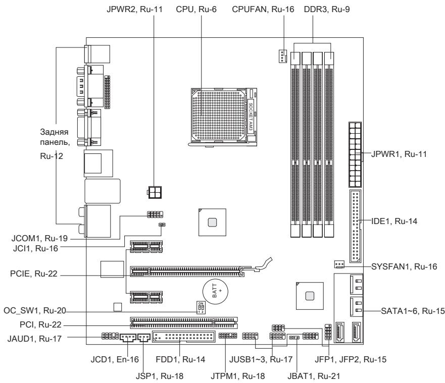
Quick Components Guide

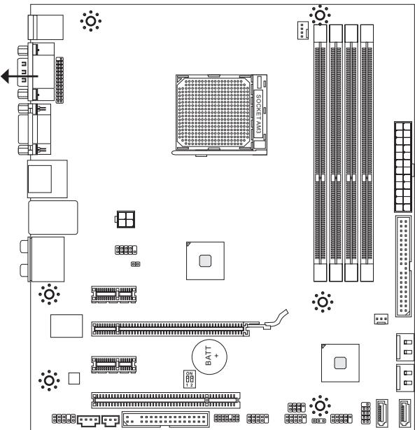
Screw Holes
When you install the mainboard, you have to place the mainboard into the chassis in the correct direction. The locations of screws holes on the mainboard are shown as below.
The side has to toward the rear, the position for the I/O shield of the chassis.
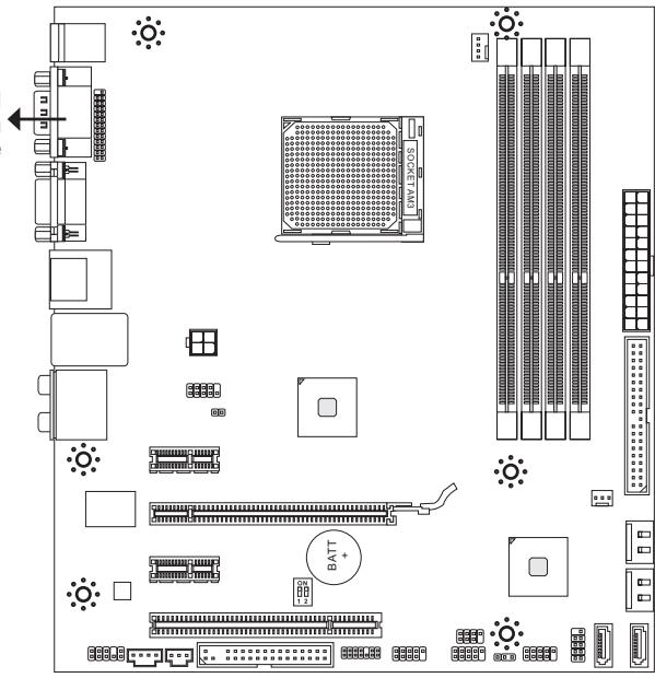

Refer above picture to install standoffs in the appropriate locations on chassis and then screw through the mainboard screw holes into the standoffs.
Important
- To prevent damage to the mainboard, any contact between the mainboard circuit and chassis or unnecessary standoffs mounted on the chassis is prohibited.
- Please make sure there is no metal components placed on the mainboard or within the chassis that may cause short circuit of the mainboard.
CPU (Central Processing Unit)
When you are installing the CPU, make sure to install the cooler to prevent overheating. If you do not have the CPU cooler, consult your dealer before turning on the computer. For the latest information about CPU, please visit http://www.msi.com/index.php?func=cpuform2
Important
Overheating
Overheating will seriously damage the CPU and system. Always make sure the cooling fan can work properly to protect the CPU from overheating. Make sure that you apply an even layer of thermal paste (or thermal tape) between the CPU and the heatsink to enhance heat dissipation.
Replacing the CPU
While replacing the CPU, always turn off the ATX power supply or unplug the power supply's power cord from the grounded outlet first to ensure the safety of CPU.
Overclocking
This mainboard is designed to support overclocking. However, please make sure your components are able to tolerate such abnormal setting, while doing overclocking. Any attempt to operate beyond product specifications is not recommended. We do not guarantee the damages or risks caused by inadequate operation or beyond product specifications.
Introduction to AM3 CPU
The surface of CPU. Remember to apply some thermal paste on it for better heat dispersion.
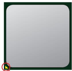
Gold arrow
CPU & Cooler Installation
When you are installing the CPU, make sure the CPU has a cooler attached on the top to prevent overheating. Meanwhile, do not forget to apply some thermal paste on CPU before installing the heat sink/cooler fan for better heat dispersion.
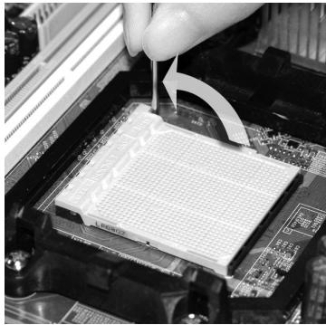
Follow the steps below to install the CPU & cooler correctly. Wrong installation will cause the damage of your CPU & mainboard.
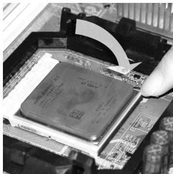
- Pull the lever sideways away from the socket. Make sure to raise the lever up to a 90-degree angle.
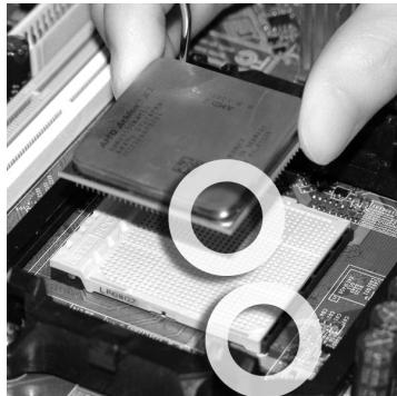
- If the CPU is correctly installed, the pins should be completely embedded into the socket and can not be seen. Please note that any violation of the correct installation procedures may cause permanent damages to your mainboard.
- Look for the gold arrow of the CPU. The gold arrow should point as shown in the picture. The CPU can only fit in the correct orientation.
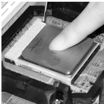
- Press the CPU down firmly into the socket and close the lever. As the CPU is likely to move while the lever is being closed, always close the lever with your fingers pressing tightly on top of the CPU to make sure the CPU is properly and completely embedded into the socket.
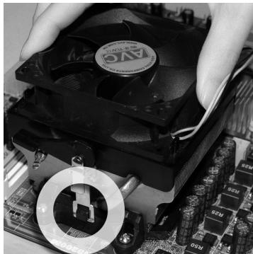
- Position the cooling set onto the retention mechanism.
Hook one end of the clip to hook first.
- Fasten down the lever.
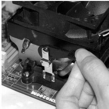
- Then press down the other end of the clip to fasten the cooling set on the top of the retention mechanism.
Locate the Fix Lever and lift up it.
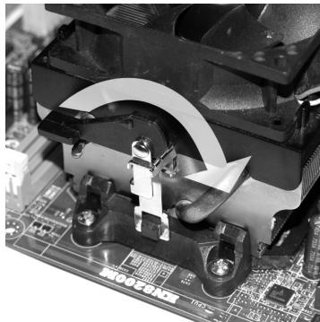
- Attach the CPU Fan cable to the CPU fan connector on the mainboard.
Important
- Mainboard photos shown in this section are for demonstration of the cooler installation for Socket AM3 CPUs only. The appearance of your mainboard may vary depending on the model you purchase.
- While disconnecting the Safety Hook from the fixed bolt, it is necessary to keep an eye on your fingers, because once the Safety Hook is disconnected from the fixed bolt, the fixed lever will spring back instantly.
Memory
These DIMM slots are used for installing memory modules.
For more information on compatible components, please visit
http://www.msi.com/index.php?func testreport
DDR3
240-pin, 1.5V
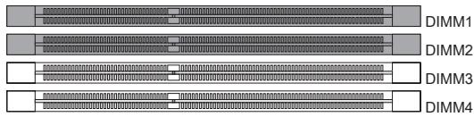
Dual-Channel mode Population Rule
In Dual-Channel mode, the memory modules can transmit and receive data with two data bus lines simultaneously. Enabling Dual-Channel mode can enhance the system performance. The following illustrations explain the population rules for Dual-Channel mode.
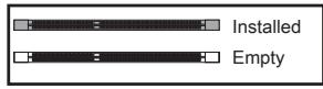
①
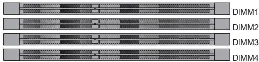
②
Important
- DDR3 memory modules are not interchangeable with DDR2 and the DDR3 standard is not backwards compatible. You should always install DDR3 memory modules in the DDR3 DIMM slots.
- In Dual-Channel mode, make sure that you install memory modules of the same type and density in different channel DIMM slots.
- To enable successful system boot-up, always insert the memory modules into the DIMM1 first.
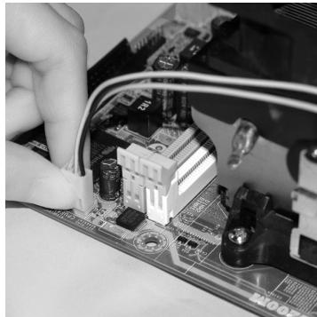
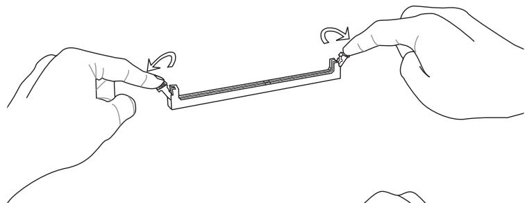
Installing Memory Modules
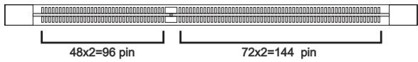
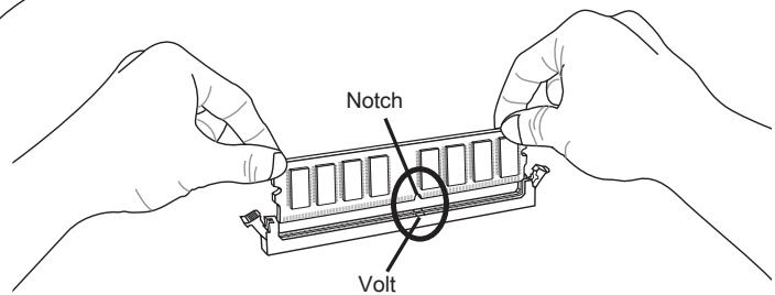
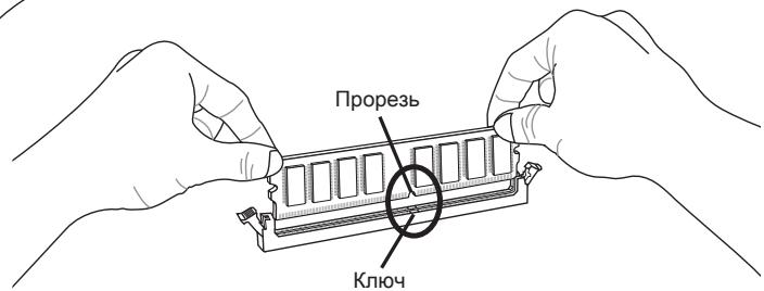
- The memory module has only one notch on the center and will only fit in the right orientation.
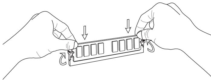
- Insert the memory module vertically into the DIMM slot. Then push it in until the golden finger on the memory module is deeply inserted in the DIMM slot. The plastic clip at each side of the DIMM slot will automatically close when the memory module is properly seated.
- Manually check if the memory module has been locked in place by the DIMM slot clips at the sides.
Important
You can barely see the golden finger if the memory module is properly inserted in the DIMM slot.
Power Supply
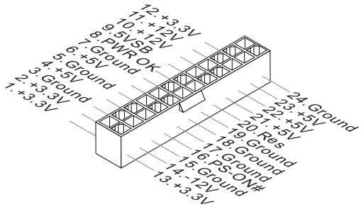
ATX 24-pin Power Connector: JPWR1
This connector allows you to connect an ATX 24-pin power supply. To connect the ATX 24-pin power supply, make sure the plug of the power supply is inserted in the proper orientation and the pins are aligned. Then push down the power supply firmly into the connector.
You may use the 20-pin ATX power supply as you like. If you'd like to use the 20-pin ATX power supply, please plug your power supply along with pin 1 & pin 13.

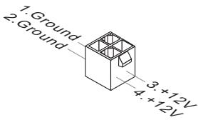
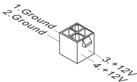
ATX 4-pin Power Connector: JPWR2
This power connector is used to provide power to the CPU.
Important
- Make sure that all the connectors are connected to proper ATX power supplies to ensure stable operation of the mainboard.
- Power supply of 400 watts (and above) is highly recommended for system stability.
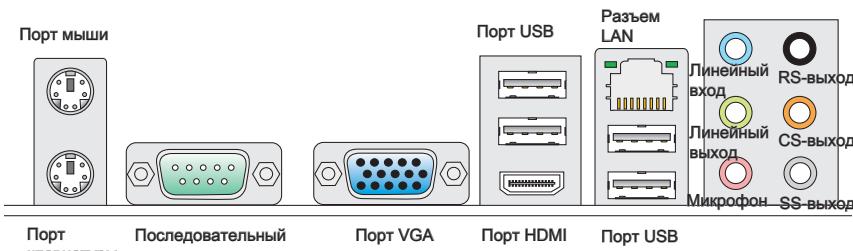
Back Panel
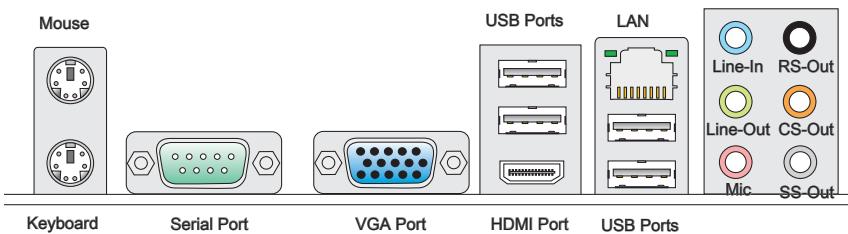
Mouse/Keyboard
The standard PS/2® mouse/keyboard DIN connector is for a PS/2® mouse/keyboard.
Serial Port
The serial port is a 16550A high speed communications port that sends/ receives 16 bytes FIFOs. You can attach a serial mouse or other serial devices directly to the connector.
VGA Port
The DB15-pin female connector is provided for monitor.
> HDMI Port
The High-Definition Multimedia Interface (HDMI) is an all-digital audio/video interface capable of transmitting uncompressed streams. HDMI supports all TV format, including standard, enhanced, or high-definition video, plus multi-channel digital audio on a single cable.
LAN
The standard RJ-45 LAN jack is for connection to the Local Area Network (LAN). You can connect a network cable to it.

| LED | Color | LED State | Condition |
| Left | Yellow | Off | LAN link is not established. |
| On(Steady state) | LAN link is established. | ||
| On(brighter & pulsing) | The computer is communicating with another computer on the LAN. | ||
| Right | Green | Off | 10 Mbit/sec data rate is selected. |
| On | 100 Mbit/sec data rate is selected. | ||
| Orange | On | 1000 Mbit/sec data rate is selected. |
USBPorts
The USB (Universal Serial Bus) port is for attaching USB devices such as keyboard, mouse, or other USB-compatible devices.
Audio Ports
These audio connectors are used for audio devices. It is easy to differentiate between audio effects according to the color of audio jacks.
- Line-In (Blue) - Line In, is used for external CD player, tape-player or other audio devices.
Line-Out (Green) - Line Out, is a connector for speakers or headphones. - Mic (Pink) - Mic, is a connector for microphones.
RS-Out (Black) - Rear-Surround Out in 4/5.1/7.1 channel mode.
CS-Out (Orange) - Center/ Subwoofer Out in 5.1/ 7.1 channel mode.
SS-Out (Gray) - Side-Surround Out 7.1 channel mode.
Connectors
Floppy Disk Drive Connector: FDD1
This connector supports 360KB, 720KB, 1.2MB, 1.44MB or 2.88MB floppy disk drive.
* The MB layout in this figure is for reference only.
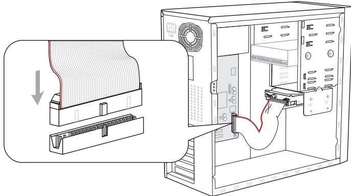
IDE Connector: IDE1
This connector supports IDE hard disk drives, optical disk drives and other IDE devices.
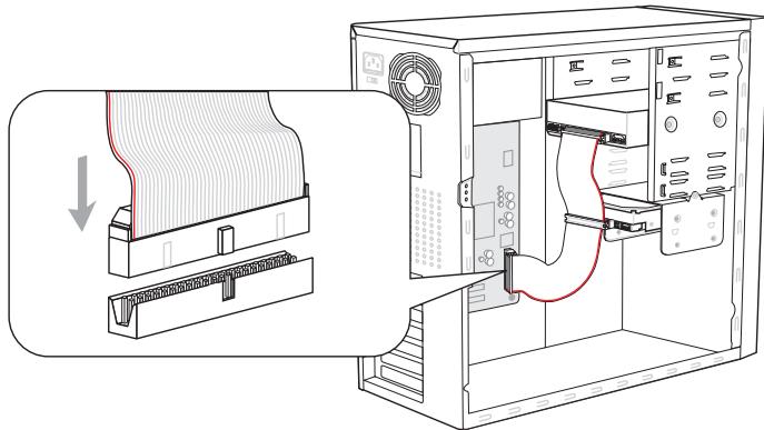
* The MB layout in this figure is for reference only.
Important
If you install two IDE devices on the same cable, you must configure the drives separately to master / slave mode by setting jumpers. Refer to IDE device's documentation supplied by the vendors for jumper setting instructions.
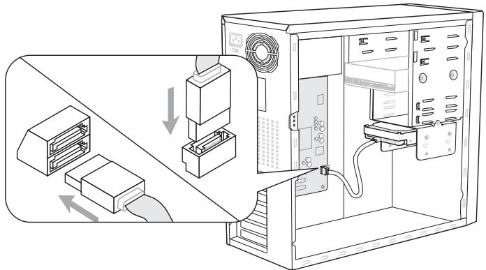
Serial ATA Connector: SATA1~6
This connector is a high-speed Serial ATA interface port. Each connector can connect to one Serial ATA device.
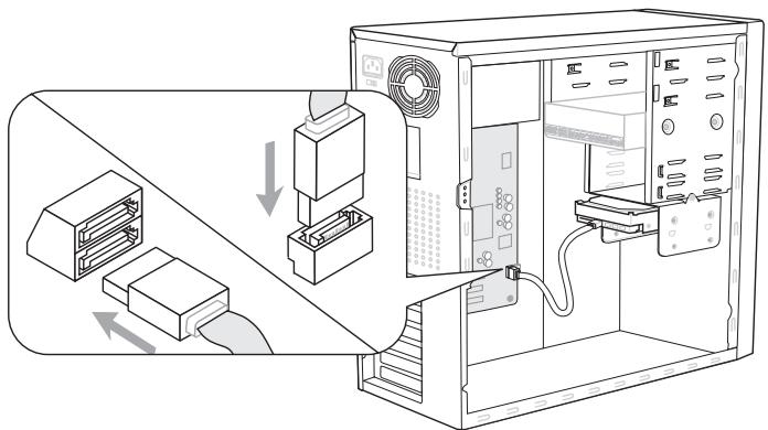
* The MB layout in this figure is for reference only.
Important
- Please do not fold the Serial ATA cable into 90-degree angle. Otherwise, data loss may occur during transmission.
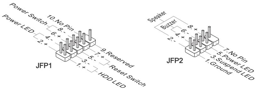
Front Panel Connector: JFP1, JFP2
This connector is for electrical connection to the front panel switches and LEDs. The JFP1 is compliant with Intel® Front Panel I/O Connectivity Design Guide.
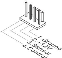
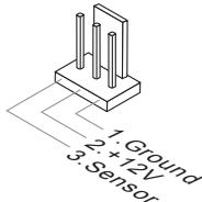
Fan Power Connectors: CPUFAN, SYSFAN1
The fan power connectors support system cooling fan with +12V . When connecting the wire to the connectors, always note that the red wire is the positive and should be connected to the +12V ; the black wire is Ground and should be connected to GND. If the mainboard has a System Hardware Monitor chipset on-board, you must use a specially designed fan with speed sensor to take advantage of the CPU fan control.
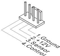
CPUFAN
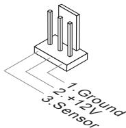
SYSFAN1
Important
- Please refer to the recommended CPU fans at processor's official website or consult the vendors for proper CPU cooling fan.
- CPUFAN supports fan control. You can install Overclocking Center utility that will automatically control the CPU fan speed according to the actual CPU temperature.
Fan cooler set with 3 or 4 pins power connector are both available for CPUFAN
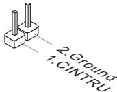
Chassis Intrusion Connector: JCI1
This connector connects to the chassis intrusion switch cable. If the chassis is opened, the chassis intrusion mechanism will be activated. The system will record this status and show a warning message on the screen. To clear the warning, you must enter the BIOS utility and clear the record.
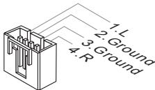
CD-In Connector: JCD1
This connector is provided for external audio input.
Front USB Connector: JUSB1/ JUSB2/ JUSB3
This connector, compliant with Intel® I/O Connectivity Design Guide, is ideal for connecting high-speed USB interface peripherals such as USB HDD, digital cameras, MP3 players, printers, modems and the like.
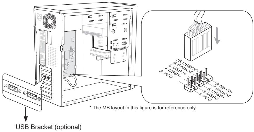
Important
Note that the pins of VCC and GND must be connected correctly to avoid possible damage.
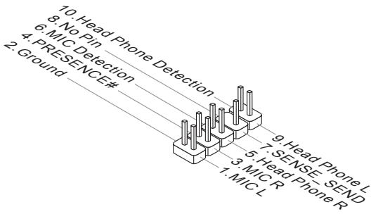
Front Panel Audio Connector: JAUD1
This connector allows you to connect the front panel audio and is compliant with Intel® Front Panel I/O Connectivity Design Guide.
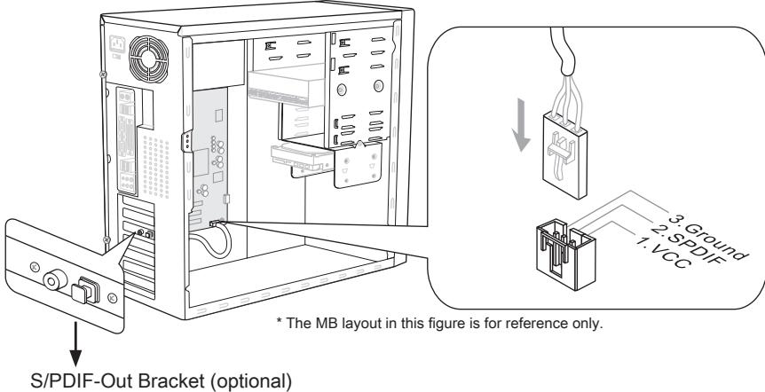
S/PDIF-Out Connector: JSP1
This connector is used to connect S/PDIF (Sony & Philips Digital Interconnect Format) interface for digital audio transmission.
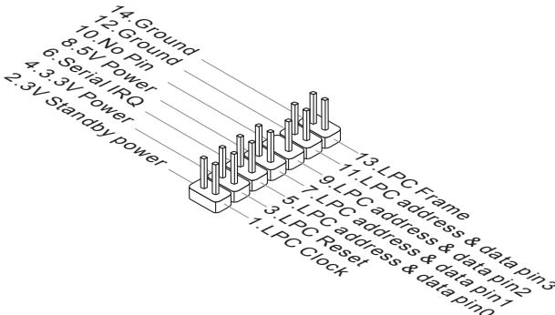
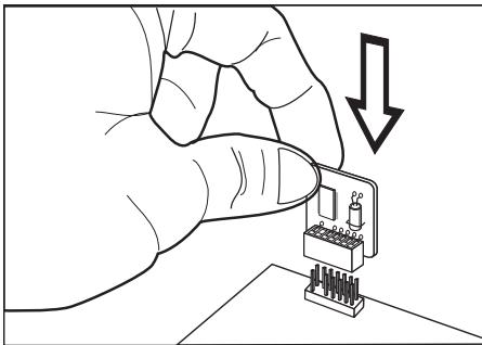
TPM Module connector: JTPM1
This connector connects to a TPM (Trusted Platform Module) module (optional). Please refer to the TPM security platform manual for more details and usages.
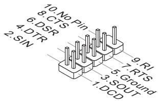
Serial Port Connector: JCOM1
This connector is a 16550A high speed communication port that sends/receives 16 bytes FIFOs. You can attach a serial device.
Switch
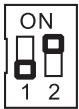
Overclock FSB Switch: OC_SW1
You can overclock the processor frequency by changing the switch. Follow the instructions below to set the CPU clock.
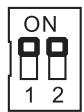
Default
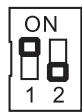
Increase 10% speed of CPU clock
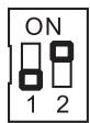
Increase 15% speed of CPU clock
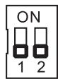
Increase 20% speed of CPU clock
Important
- Make sure that you power off the system before setting the switch.
- When overclocking cause system instability or crash during boot, please set the switch to default setting.
Jumpers
Clear CMOS Jumper: JBAT1
There is a CMOS RAM onboard that has a power supply from an external battery to keep the data of system configuration. With the CMOS RAM, the system can automatically boot OS every time it is turned on. If you want to clear the system configuration, set the jumper to clear data.

JBAT1

Keep Data

Clear Data
Important
You can clear CMOS by shorting 2-3 pin while the system is off. Then return to 1-2 pin position. Avoid clearing the CMOS while the system is on; it will damage the mainboard.
Slots
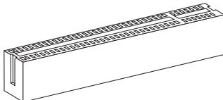
PCIE (Peripheral Component Interconnect Express) Slot
The PCIE slot supports the PCIE interface expansion card.
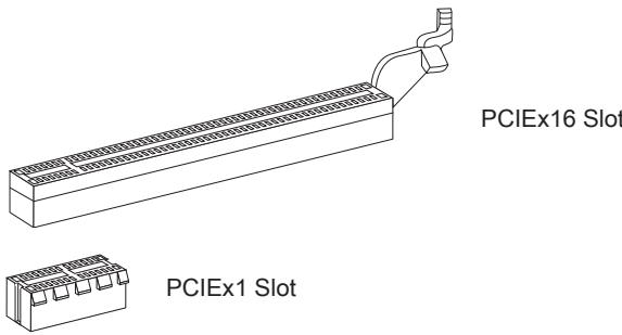
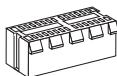
PCI (Peripheral Component Interconnect) Slot
The PCI slot supports LAN card, SCSI card, USB card, and other add-on cards that comply with PCI specifications.
Important
When adding or removing expansion cards, make sure that you unplug the power supply first. Meanwhile, read the documentation for the expansion card to configure any necessary hardware or software settings for the expansion card, such as jumpers, switches or BIOS configuration.
PCI Interrupt Request Routing
The IRQ, acronym of interrupt request line and pronounced I-R-Q, are hardware lines over which devices can send interrupt signals to the microprocessor. The PCI IRQ pins are typically connected to the PCI bus pins as follows:
| Order1 | Order2 | Order3 | Order4 | |
| PCI Slot1 | INT E# | INT F# | INT G# | INT H# |
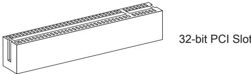
LED Status Indicators
APS LED Status Indicator: LED1
These APS (Active Phase Switching) LED indicates the current CPU power phase mode. Follow the instructions below to read.
[ ]
| ON | The LED will light when CPU is in 3 phase power mode. |
| OFF | The LED will go off when CPU is in 1 phase power mode. |
BIOS Setup
This chapter provides basic information on the BIOS Setup program and allows you to configure the system for optimum use. You may need to run the Setup program when:
- An error message appears on the screen during the system booting up, and requests you to run BIOS SETUP.
- You want to change the default settings for customized features.
Important
- The items under each BIOS category described in this chapter are under continuous update for better system performance. Therefore, the description may be slightly different from the latest BIOS and should be held for reference only.
- Upon boot-up, the 1st line appearing after the memory count is the BIOS version. It is usually in the format:
A7623AMS V2.3 043010 where:
1st digit refers to BIOS maker as A = AMI , W = AWARD , and P = PHOENIX . 2nd - 5th digit refers to the model number.
6th digit refers to the chipset as I = Intel, N = NVIDIA, A = AMD and V = VIA. 7th - 8th digit refers to the customer as MS = all standard customers.
V2.3 refers to the BIOS version.
043010 refers to the date this BIOS was released.
Entering Setup
Power on the computer and the system will start POST (Power On Self Test) process. When the message below appears on the screen, press key to enter Setup.
Press DEL to enter SETUP
If the message disappears before you respond and you still wish to enter Setup, restart the system by turning it OFF and On or pressing the RESET button. You may also restart the system by simultaneously pressing <Ctrl> , <Alt> , and <Delete> keys.
Getting Help
After entering the Setup menu, the first menu you will see is the Main Menu.
Main Menu
The main menu lists the setup functions you can make changes to. You can use the arrow keys (↑↓) to select the item. The on-line description of the highlighted setup function is displayed at the bottom of the screen.
Sub-Menu
If you find a right pointer symbol appears to the left of certain fields that means a submenu can be launched from this field. A sub-menu contains additional options for a field parameter. You can use arrow keys (↑↓) to highlight the field and press
General Help
The BIOS setup program provides a General Help screen. You can call up this screen from any menu by simply pressing <F1> . The Help screen lists the appropriate keys to use and the possible selections for the highlighted item. Press <Esc> to exit the Help screen.
The Main Menu
Once you enter BIOS CMOS Setup Utility, the Main Menu will appear on the screen. The Main Menu allows you to select from the setup functions and two exit choices. Use arrow keys to select among the items and press
| Standard CMOS Features | Cell Menu |
| Advanced BIOS Features | M-Flash |
| Integrated Peripherals | Overclocking Profile |
| Power Management Setup | Load Fail-Safe Defaults |
| H/V Monitor | Load Optimized Defaults |
| Green Power | Save & Exit Setup |
| BIOS Setting Password | Exit Without Saving |
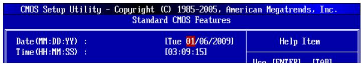
Standard CMOS Features
Use this menu for basic system configurations, such as time, date etc.
Advanced BIOS Features
Use this menu to setup the items of special enhanced features.
Integrated Peripherals
Use this menu to specify your settings for integrated peripherals.
Power Management Setup
Use this menu to specify your settings for power management.
H/W Monitor
This entry shows your PC health status.
Green Power
Use this menu to specify the power phase.
BIOS Setting Password
Use this menu to set the password for BIOS.
Cell Menu
Use this menu to specify your settings for frequency/voltage control and overclocking.
M-Flash
Use this menu to read/ flash the BIOS from storage drive (FAT/ FAT32 format only).
Overclocking Profile
Use this menu to save/ load your settings to/ from CMOS for BIOS.
Load Fail-Safe Defaults
Use this menu to load the default values set by the BIOS vendor for stable system performance.
Load Optimized Defaults
Use this menu to load the default values set by the mainboard manufacturer specifically for optimal performance of the mainboard.
Save & Exit Setup
Save changes to CMOS and exit setup.
Exit Without Saving
Abandon all changes and exit setup.
When entering the BIOS Setup utility, follow the processes below for general use.
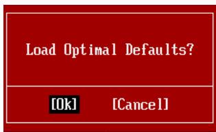
- Load Optimized Defaults: Use control keys ( ) to highlight the Load Optimized Defaults field and press
, a message as below appears:
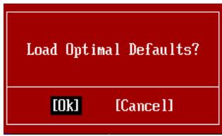
Select [Ok] and press Enter to load the default settings for optimal system performance.
- Setup Date/ Time : Select the Standard CMOS Features and press
to enter the Standard CMOS Features-menu. Adjust the Date, Time fields.
- Save & Exit Setup: Use control keys ( ) to highlight the Save & Exit Setup field and press
, a message as below appears:

Select [Ok] and press Enter to save the configurations and exit BIOS Setup utility.
Important
The configuration above are for general use only. If you need the detailed settings of BIOS, please see the complete version of English manual on MSI website.
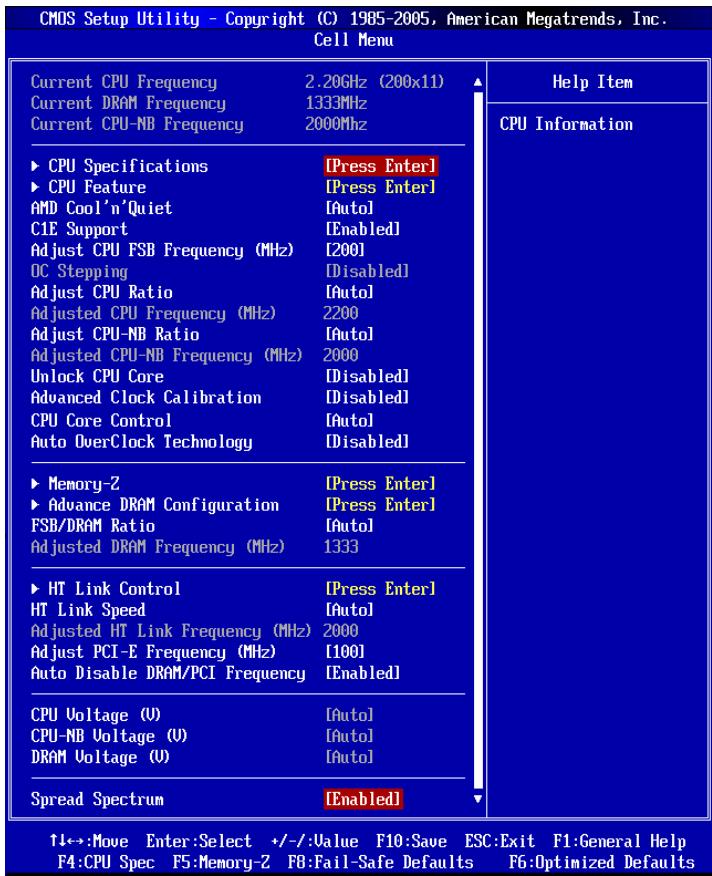
- Cell Menu Introduction : This menu is for advanced user who want to overclock the mainland.
Important
Change these settings only if you are familiar with the chipset.
Current CPU / DRAM / CPU-NB Frequency
These items show the current clocks of CPU, Memory and CPU-NB speed. Read-only.
CPU Specifications
Press
CPU Technology Support
Press
CPU Feature
Press
AMD Cool'n'Quiet
The Cool'n'Quiet technology can effectively and dynamically lower CPU speed and power consumption.
C1E Support
To enable this item to red the CPU power consumption while idle. Not all poressors support Enhanced Halt tate (C1E).
SVM Support
This item allows you to enable/disable the AMD SVM (Secure Virtual Machine) Technology.
AMD Cool'n'Quiet
The Cool'n'Quiet technology can effectively and dynamically lower CPU speed and power consumption.
C1E Support
To enable this item to red the CPU power consumption while idle. Not all poressors support Enhanced Halt tate (C1E).
Important
To ensure that Cool'n'Quiet function is activated and will be working properly, it is required to double confirm that:
-
Run BIOS Setup, and select Cell Menu. Under Cell Menu, find AMD Cool'n'Quiet, and set this item to "Enabled".
-
Enter Windows, and select [Start]->[Settings]->[Control Panel]->[Power Options]. Enter Power Options Properties tag, and select Minimal Power Management under Power schemes.
Adjust CPU FSB Frequency (MHz)
This item allows you to select the CPU Front Side Bus clock frequency (in MHz).
OC Stepping
This item will be enabled after you set the overclocking frequency in the "Adjust CPU Base Frequency (MHz)". And the following items will appear. This items will help the system to overclock step by step after system booting up.
Start OC Stepping From (MHz)
This item is used to set the initial base clock. The system will boot with the initial base clock, and start to overclock from initial base clock to set base clock that you set in "Adjust CPU FSB Frequency (MHz)" step by step.
OC Step
This item is used to set how many steps for base colck overclocking.
OC Step Count Timer
This item is used to set the buffer time for every step.
Adjust CPU Ratio
This item is used to adjust CPU clock multiplier (ratio). It is available only when the
processor supports this function.
Adjusted CPU Frequency (MHz)
It shows the adjusted CPU frequency. Read-only.
Adjust CPU-NB Ratio
This item is used to adjust CPU-NB ratio.
Adjusted CPU-NB Frequency (MHz)
It shows the adjusted CPU-NB frequency. Read-only.
Unlock CPU Core
This item allows you to unlock the additional cores, you could set it [Enabled] and then set Advanced Clock Calibration [Auto] in order to be able to activate the processor cores.
Advanced Clock Calibration
This item is for overclock. Setting to [Auto] allows you to set the CPU Ratio higher. It is available only when the processor supports this function.
CPU Core Control
This item is used to control number of CPU cores. When set to [Auto], the CPU will operate under the default number of cores. When set to [Manual], you will be able to enable/disable the specific CPU core.
Core 1/2/3/4
These items are used to enable/disable the core 1/2/3/4.
Auto OverClock Technology
Setting this item to [Max FSB] allows the system to detect the maximum FSB clock and to overclock automatically. If overclocking fails to run, you can try the lower FSB clock for overclocking successfully.
Memory-Z
Press
DIMM1~4 Memory SPD Information
Press
Advance DRAM Configuration
Press
DRAM Timing Mode
Select whether DRAM timing is controlled by the SPD (Serial Presence Detect) EEPROM on the DRAM module. Setting to [Auto] enables DRAM timings and the following "Advance DRAM Configuration" sub-menu to be determined by BIOS based on the configurations on the SPD. Selecting [Manual] allows users to configure the DRAM timings and the following related "Advance DRAM Configuration" sub-menu manually.
FSB/DRAM Ratio
This item allows you to select the ratio of FSB/ DRAM.
Adjusted DRAM Frequency (MHz)
It shows the adjusted Memory frequency. Read-only.
HT Link Control
Press
HT Incoming/Outgoing Link Width
These items allow you to set the Hyper-Transport Link width. Setting to [Auto], the system will detect the HT link width automatically.
HT Link Speed
This item allows you to set the Hyper-Transport Link speed. Setting to [Auto], the system will detect the HT link speed automatically.
Adjusted HT Link Frequency (MHz)
It shows the adjusted HT Link frequency. Read-only.
Adjust PCI-E Frequency (MHz)
This field allows you to select the PCIE frequency (in MHz).
Auto Disable DRAM/PCI Frequency
When set to [Enabled], the system will remove (turn off) clocks from empty DRAM/PCI slots to minimize the electromagnetic interference (EMI).
CPU Voltage (V)/CPU-NB Voltage (V)/DRAM Voltage (V)
These items are used to adjust the voltage of CPU, Memory and chipset.
Spread Spectrum
When the mainboard's clock generator pulses, the extreme values (spikes) of the pulses create EMI (Electromagnetic Interference). The Spread Spectrum function reduces the EMI generated by modulating the pulses so that the spikes of the pulses are reduced to flatter curves. If you do not have any EMI problem, leave the setting at Disabled for optimal system stability and performance. But if you are plagued by EMI, set to Enabled for EMI reduction. Remember to disable Spread Spectrum if you are overclocking because even a slight jitter can introduce a temporary boost in clock speed which may just cause your overclocked processor to lock up.
Important
- If you do not have any EMI problem, leave the setting at [Disabled] for optimal system stability and performance. But if you are plagued by EMI, select the value of Spread Spectrum for EMI reduction.
- The greater the Spread Spectrum value is, the greater the EMI is reduced, and the system will become less stable. For the most suitable Spread Spectrum value, please consult your local EMI regulation.
- Remember to disable Spread Spectrum if you are overclocking because even a slight jitter can introduce a temporary boost in clock speed which may just cause your overclocked processor to lock up.
Important
Failed Overclocking Resolution
This mainboard supports overclocking greatly. However, please make sure your peripherals and components are bearable for some special settings. Any operation that exceeds product specification is not recommended. Any risk or damage resulting from improper operation will not be under our product warranty.
Two ways to save your system from failed overclocking...
Reboot
Press the Power button to reboot the system three times. Please note that, to avoid electric current to affect other devices or components, we suggest an interval of more than 10 seconds among the reboot actions.

At the fourth reboot, BIOS will determine that the previous overclocking is failed and restore the default settings automatically. Please press any key to boot the system normally when the following message appears on screen.
Warning !!! The previous overclocking had failed, and system will restore its defaults setting, Press any key to continue......
Clear CMOS
Please refer to "how to clear CMOS data" section for more information about how to clear CMOS data.
Software Information
Take out the Driver/Utility DVD that is included in the mainboard package, and place it into the DVD-ROM drive. The installation will auto-run, simply click the driver or utility and follow the pop-up screen to complete the installation. The Driver/Utility DVD contains the:
- Driver menu : The Driver menu shows the available drivers. Install the driver by your desire and to activate the device.
- Utility menu : The Utility menu shows the software applications that the mainboard supports.
Important
Please visit the MSI website to get the latest drivers and BIOS for better system performance.

Deutsch
880GM-E41
Serie
Spezifikationen
Prozessoren
Frontpanel Anschlüsse: JFP1, JFP2
Press DEL to enter SETUP
| Standard CMOS Features | Cell Menu |
| Advanced BIOS Features | M-Flash |
| Integrated Peripherals | Overclocking Profile |
| Power Management Setup | Load Fail-Safe Defaults |
| H/V Monitor | Load Optimized Defaults |
| Green Power | Save & Exit Setup |
| BIOS Setting Password | Exit Without Saving |
Standard CMOS Features
Advanced BIOS Features
Integrated Peripherals
BIOS Setting Password
Overclocking Profile
CPU Technology Support
Adjust CPU FSB Frequency (MHz)
Adjusted CPU Frequency (MHz)
Adjusted CPU-NB Frequency (MHz)
Advanced Clock Calibration
Adjusted DRAM Frequency (MHz)
HT Incoming/Outgoing Link Width
Adjusted HT Link Frequency (MHz)
Adjust PCI-E Frequency (MHz)
CPU Voltage (V)/CPU-NB Voltage (V)/DRAM Voltage (V)
Warning !!! The previous overclocking had failed, and system will restore its defaults setting, Press any key to continue......
Clear CMOS
Emplacement PCIE (Peripheral Component Interconnect Express)
Emplacement PCI (Peripheral Component Interconnect)
Press DEL to enter SETUP
| Standard CMOS Features | Cell Menu |
| Advanced BIOS Features | M-Flash |
| Integrated Peripherals | Overclocking Profile |
| Power Management Setup | Load Fail-Safe Defaults |
| H/V Monitor | Load Optimized Defaults |
| Green Power | Save & Exit Setup |
| BIOS Setting Password | Exit Without Saving |
Standard CMOS Features (Fonctions CMOS standard)
CPU Technology Support
Start OC Stepping From (MHz)
Adjusted CPU Frequency (MHz)
Adjusted CPU-NB Frequency (MHz)
Advanced Clock Calibration
Adjusted DRAM Frequency (MHz)
HT Incoming/Outgoing Link Width
Adjusted HT Link Frequency (MHz)
Adjust PCI-E Frequency (MHz)
- CPU Voltage (V)/CPU-NB Voltage (V)/DRAM Voltage (V)
Warning !!! The previous overclocking had failed, and system will restore its defaults setting,
Press any key to continue.....
Effacer CMOS
1 pnonnp npT
-Подэржka 1 FDD c 360KB,720KB,1.2MB,1.44MB n 2.88MB
KOHHEKTopbi
3aDnei naHelen
-1PS/2nopTmbiHn
-1PS/2npTKnabnAtypbl
-1pa3bem nocneoBateBhoTnopta
- 1 nopT HDMI
- 1 nopTVGA
- 4 nopTa USB 2.0
- 1 pa3bem LAN
- 63ByKOBbIX pa3bEmOB c rN6KIM nepeHa3NaeHHeM
Pa3bembl, yctaHOBJeHHbIe Ha nnate
- 3 pa3bema USB 2.0
- 1 pa3bem nocleobatehno npota
-1pa3bem CD-In - 1 pa3bem Длг NOdkluoyehnaудno Ha nepeidne naheJIi
- 1 pa3bem SPDIF-Out
- 1 pa3bem DaTcHka OTKpbBaHnK Kopnyca
-1pa3bemTPM - 1 pa3bem npapannelbHoro nopTa
-1pepeknouateIb
CnotbI
1 cnot PCI Express x16
2 cnota PCI Express x1
1 cnotPCI, noidepka nHTeppeca PCI uHbI c nTahnem 3.3V/5V
ΦopM ΦaKTop
Micro-ATX (24.4cm× 20.0cm)
KpennneHne
6 OTBepCTn DnI KpePJIeHnI
(Помоць в пиобретени доролнітelveх akceccуаров и поcke Homepa n3delenno MoKHO naHTn no aDpecy
http://www.msi.com/index.php)
Pa3MeueHne KOMNoHEtOB CnCTeMHoI PJIaTbI
OTBepCTnIy BnHTOB
Pn yctaHOBKe CnCTeMHo NnTaBt HxKHO BcTaBntb eB B KOpNyc B npaBnIbHOM HnnpaBHeHn. Pa3MeueHnra OTBepCtn dIy BNHTOB NOKa3aHbI Hnke.
Бokobbie cToPOhblcneDyETnPoTnB3aHHeROKpNyca,pa3MeUeHneIdI npTeKTopa BxOda/BbXOda KOpNyca.

→
OTBepCTnIy IINHTOB
CneyuTe yka3aHnM BblIe yka3aHHo Iy TaHOBKn DepkaTeJIeB NpabINbHOM MeCTe B Kopnyce n 3aTe M BBNHTte BnHTbI uepe3 OTBepCTNЯ dIy BNHTOB B DePKaTeJI.
Bhuvahine
Bo n36eKaHne nobpeKdEHH K cNCTeMHoI pNaTe, IIObO KoNTaKT MeJdy npOBQkAMn CnCTeMHoI pNaTbI N KopnycOM mII Neob8aTeIbHbI DePkaTeIb yCTaHOBJIeH B Kopnyce 3anpeSeH.
- Y6eIntecb B TOM,чTo Ha CnCTeMHoN Pnate NnB KOpnyce HeT HnKaKOrO MetaJIuYeCKOrO KOMNoHEHTa, KOTOpBI MOKeT Bbl3BaTb 3aKOpaUHbAHe CnCTeMHoN Pnate.
CPU (LêntpaJbHbI npoceccop)
Pn yctaHOBKe CPU, uTo6bI y6peey npoecccop ot neperpeBa, He 3a6yDbTe yCTaHOBt npoecccophny KJep. EcnNy Bac HET npoecccopHoro KJepa, nojkayncta, CBxKNTecb C dInepom C cIeblIO npio6peTeHn I erO yCTaHOBKn Do TORO, KaK BkIIOuHTe KOMNbHOTep.
UcTaHOBKa MoDyJIe NAmrTn
- Moулп памятп IMeOT Ondу npope3bВ cpeIeHneЧа'tn. Moуль boйдТВ pa3beM TOlbko pri npabuJIbHoI opHeNTaци.
- BCTaBte MoyIb B DIMM cnot B BeptnKaJIbHOM HappaJIeHNI. 3aTeM haxMtte Ha Hero, yTo6bl 3oJooHeHie KOHTaKtbl rJy60KO nOrpy3uINcB DIMM cnot. Ecnn MoyIb pAmrTn BCTaBJIeH npaBnJIbHO, To pNaCTnKOBbIe 3aUeJIKN Ha o6Ox KOHcX 3aKpOHTCa ABTomATnueckN.
- BpyuHny u6eHntecb, yTo MoDyIb 3aKpeIenneB CcnoTe DIMM 3aUeJIkamn c o6eHX cTOpOH.
BHMaHue
30nOble KOHTaKtbl eBb BnHbI, ecN MoynPiMaTn npaBnIbHO pa3MeueHbIBDIMCnote.


Pa3bem nHTaHnA
24-KoHTaKTbIpa3bEMnTAnHrATX:JPWR1
3TOT pa3bem NO3BONJET NOKNIHOnTb 24-KoHTaKTbI KOHKeTOp nITaHnA ATX. IJIra erO noKJIIOUeHnY y6eINTEcb, YTO KOHKeTOp N KOHTaKtbl pa3bema nPaBUNbHO copHeHTnpOBaHbI. 3aTeM nIoTHo BCTaBbTe erO b pa3bem Ha CnCTEmHO nIaTe.
BbI TaKke MoKTe NcNoJIb3OBAtB 20-KoHTaKTHbIy ATX 6nok nTahnI. PpN IcNoJIb3OBAHmN 20-KoHTaKTHOro pa3beMa, NOdKJIouaYte erO BDoJI bKOHTaKToB 1 n 13.
4-KONTaKTHbI pa3bem nHTaHnA TX: JPWR2
3TOT pa3bem nHTaHnI NCNoIb3yETc IЯ OeBcepeHnI nTaHnI pOuceccopa.
BhimaHue
- Y6eintecb B TOM,чTo BCE pa3beMbI NOdkHouyeHbI K nCTOCHKam NHTAHnA ATX dJa CTaBbHOH pa60tBu CNTcEMHOJIaTbI.
- Πястбиьности системы HabToTeIbHo peKOMeHdyeTcЯ nCNoIb3OBAt b NCTOCHN KNTaHnHa 400 Bt (И ВblSe).
3aHЯ nHaHeJIb
-TopMbUn/KnaBnAtypbI
CtahdapThbIe pa3bEmbl DIN PS/2® dIЯ nOdkJIouChEnIaIIH/KnaBnAtypbl c HInTepeFeiom PS/2®.
PocneObaTeIbHbI npT
* KomnoentbI CNTeMHNo INaTbI B IN3o6paJKeHn TOnIbKO dIa CnpAByK.
BhimaHne
- 136eaiTe, noxayuHcTa, pe3Knx u3n6oB ka6eIa Serial ATA. B npotubom clyae MOryT Bo3HKnHyTb nOteprn daHHbIX npu nepedaue.
KoHneKTopbI nepeDHeN naHeN: JFP1, JFP2
Pa3bem nIITaHnB eHTnJIrTopoB: CPUFAN, SYSFAN1
Pa3bEmbl nHTaHnBEHTNJLTopOB NOdEepKINBaOT BeHTNJLTopblc nHTaHnEM +12B. PnI nOdkJIOUeHHn Heo6XoJIMOn NOMNtB, yTO KpaChbI pNOBOD nOdkJIOUaETcR KShIne +12B, YepHbI - K 3eMlne GND. Ecnn Ha cncTeMHNo INaTe yCTaHOBJIHa MmKpOcxema annapatHoro MOHITOpHHra, Heo6XoJIMOn IcNoJIb3OBAtB CneIaJIbHbIe BEHTNJLTopblc DaTchNKAMn CKOPoCTn DnpeAanImaunФyHKIun UnpaBNeHHa BeHTNJLTopamn.
CPUFAN
SYSFAN1/ SYSFAN2
BHMaHue
- YTo6bI y3HaTb O MoDJIeJX NDoXoJIuNX BeHTnIaTOpOB, ObaTnTeCb, IoxaIyIcTa, Ha OfNuaJIbHbI Be6 caT nII npOKOHcyJIbTIpyuYTeCb C npOdaBcOM.
- CPUFAN noДeрЖиBaET упавление ckОposью Врашения BeHTnIЯTopа. Ддг abTomatUcheCKOrO KOHTPOnA ckОposТи BeHTnIЯTopa npOceccopa, 3abNcIaSei OT TempepaTpybI npOceccopa и сntembl, можно установы Overclocking Center.
Pa3bemCPUFAN noDnepKnBaet BeHTnIaTOpbl, KaC 3, TaK n C 4 KOHTaTAMN.
Pa3bem DaTUnka OTKpbBaHnK Kopnyca: JCI1
CkopoocTb FSB NOBblIaetcra Ha 15%
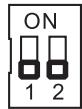
Ckopoctb FSB NOBbIaetcra Ha 20%
BHTMAHHE
Cnot PCIE (Peripheral Component Interconnect Express)
CnotPCIExpressnoDnepKnBaet KapTbIpacuipenHnINTepcecaPCI Express.
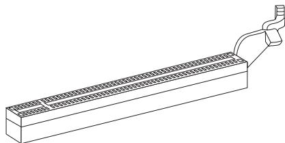
PCIEx16 cnot
PCIEx1 cnot
Cnot PCI (Peripheral Component Interconnect)
CnotPCI no3Bolraet yctahOBnTB KapbI LAN, SCSI, USB nDpyrme doonHnTeNbHbIe KapbI paacupeHn, KOtOpblc COOTBeTCTByOT cneunfkaunn PCI.
32-bitPCIcnot
BHIMAHINE
Ipepe yctahOBKO uINu IN3BLeueHem KapT pacuHpeHn y6eNTecb, yTO Ka6enb nITAHnO TKNUChEN OT 3NeKtpuWecko cTeN. IpoTuTE DOKyMeHTaCuH No KApTy pacuHpeHn N BblONHIne Heo6xOdHMble annapaTHbE uIN npOrpaMhBe yCTAHOBKn dJaHHo INaTbI, TaKne KaK nepeMbUcKn, nepeKluOaTeIN uIN KOHfNpyauCIO BIOS.
CBeTOBbIe HnDnKaTObpI

INdikatop APS:LED1
3TN INdikatopbl APS (Active Phase Switching) noka3bIbaHT pekIM pa6oTbI INCTOCHNka pNTaHnI npoecccopa. INΦopMaunO coCTOHN INdikatopOB npINBeHeHa B Ta6JInce.
LED1
1a86kBa COOTBETCTByeT u3roTOBnTeIIO BIOS (A = AMI, W = AWARD n P = PHOENIX).
Cneyuoune 4 ucbpbcooTBeCTbYIOHmOpy Moen.
Cnéýuǒaāyú KBa obo3hauaet noctabuŋka yinnceta (I = Intel, N = Nvidia, A = AMD, n V = VIA).
2 cneyuüne 6kykbl o603naayot 3ka3yika MS = ctaHapTbIy 3ka3yik.
V2.3 COOTBETCTByeT HOMepy BepCuNBIOS.
043010 -ДаТа Вынчka BIOS.
Bxod BpeXIM HacTpoKn
BkIIOHTe pntaHne KOMNbIOTepa. Pn3TOM 3aynctntc npoceDypa POST (TeCT BKNUChEHHa NtAHn).KOrda Ha 3KpaHe NOBNTC npuBeDeHHoe HnKe coo6ueHHe, HaxMITE KNaBnSy < DEL> dIy BxOa DpeKIM HacTPOKn.
Press DEL to enter SETUP
(HaXmnte DEL nIy BxoJaB SETUP)
EcHn coo6ueHHe nCye3IIO, a BbI He ycneIe HaxaTb KnaBnSy, nepe3anyCTnte CnCTeMy, BbIKNoUH IN CHOBA BKnOuHb NITaHne, INN HaxaB KhoNky RESET. MoKHO, TaKKe, nepe3anyCTntb CnCTeMy, HaxaB OndOBpemEnHO KnaBnSIu
Pexim HactpoiK
BoiIaBpeXIMHactpoiKn, BbIcpa3y yBvndTe IlaBHOe MeHIO.
Main Menu (Главhoe мени)
Главhoe MeHIO coDEpXHT CnICOK HAcTpoE, KOTOpBIE Bbl MoKTe N3MeHNT.ДЯ BbIbopa moKHO nCNoJIb3OBAbT KJIaBNIu CO CTpeKNaMn (↑↓).CnpabKa O bblpaHHOH NaCTpoKe OTo6paKaaeTcB HnKHe YactN 3KpaHa.
Повменно
EcnBbObHApYKNTe,TO CnBea OT nyHKTa MeHIO NMeETc 3HaK npaBOr yka3aTeJRA 3To O3NaHaeT HaNInue NeODMeHIO, CoDEPKaUero DOnONHITeNbHbIe HAcTPOiKN KOTOpBle MOxH0 CDeJaTb B 3Tom NyHKTe. NcNoNb3yIte YnpabJIHOUne KlaBnSi (↑ ↓) dIra BB6opa, a 3aTeM HaxMtTe
Подробна справka
B pexime hactpoikn BIOS nmeetc B03MOXHOCTb nonyehnna npdo6ho ncpaBKn. Ee moxho Bbl3BaT b3 JIO6O ro MeHIO npocTbIM HaxaTneM < F1> .B OKHe cnpaBKn 6ydt nepeuNCJIeHb BCE BO3MOXHbIe HactpoiKn B Bbl6paHHOM nyHKTe MeHIO.Haxmnte < Esc> dIra BblKJIUOeHnO kHa cnpaBKn.
The Main Menu (Главhoe мени)
Pn Bxode B pexkIM hactpoKIN BIOS Ha 3kpahe OTo6paxaetcra TnaBHOe MeHIO. TnaBHOe MEHIO N03BOJRAET Bb6paTb FyHKmN HAcTPOKIN N IMeET DBa BapnAHTa BbIXOda. IJIpepeMeJeHnI NO NyHKtAM NCNoJIb3yOTcR KNaBUn Co cTrpeKamN
| Standard CMOS Features | Cell Menu |
| Advanced BIOS Features | M-Flash |
| Integrated Peripherals | Overclocking Profile |
| Power Management Setup | Load Fail-Safe Defaults |
| H/V Monitor | Load Optimized Defaults |
| Green Power | Save & Exit Setup |
| BIOS Setting Password | Exit Without Saving |
Standard CMOS Features (CTaHdapTHbIe yHKuIN CMOS)
3To MeHIO N03BOJRAET YCTAHOBITb OCHOBHbIe napameTpbl KOHpHrypaunn CnCTembl (daTy, Bpemr n T.I.).
Advanced BIOS Features (Дононтелови Ксии BIOS)
3To MeHIO INcOJIb3YeTcAДЯ NaCTPOIeKIN CpeIaJIbHbIXΦyHKI.
Integrated Peripherals (BcTpoeHbIe nepupeprnHbIe yctpoiCTa)
3To MeHIO NcNoJIb3yeTcra dIy HAcTpoiKn IapaMeTPOB BCTpoeHHbIX nepuΦepnHbIX yCTpoiCTB.
Power Management Setup (Hactpojka ynpablenia nitaHnem)
3To MeHIO No3BOJRAET 3aDaTb napaMeTpbl ynpaBHeHn IINTaHnEM CNTeMbI.
H/W Monitor (MonHTop annapathouactn)
3TOT nyHKT OTO6paxaET COCTOHNHe annapathNo Yactn PIK.
Green Power
3To MeHIO INcNoIb3yETcIaIpeKIMoB 3HePrc6bepeKeHnA.
BIOS Setting Password (Парол дocунka Кестоюкам BIOS)
3To MeHIO NcnoJIb3yETcra, YTO6bl 3aDaTb npOJIb.
Cell Menu (MeHIO y3Ja "Cell")
3To MeHIO N03BOJIeT ynpaBJIaTb TaKTOBbIMu YactOTAMN IN HaprJxehnMaMn npi pa3roHe CNTEmbl.
M-Flash
IcnoB3yetcTЯ qTeHn/ npoWNbKn BIOS c BHeuHero NaKoNtEJa (ToNbKO FAT/FAT32).
Overclocking Profile
IcnoIb3yeTcI ypaHEnIy 3arpy3kn npaMeTpoB V/ n3 CMOS BIOS.
Load Fail-Safe Defaults
3To MeHIO NcNoIb3yETcT dTn 3aRpy3Kn 3NaueHnBIOS, yCTaHOBJIeHHbIX npOn3BOIDTeMe nTn CTaBnBHO pa6Otbl CNTEmbl.
Load Optimized Defaults (YcTaHOBnTb ONTmAmNbHbHe NaCTpoKn)
3To MeHIO NcNoJIb3YeTc DnI 3aRpy3KN HAcTpoEK N3rOToBtTeJI DnI ONTImaJIbHOI npOn3BOuNTeJIbHOCTN CnCTeMHoN INaTBI.
Save & Exit Setup (BbIXoI c coxaHeHem HacTpoEk)
3aIncb nImMeHenn B CMOS n BbIXoN n3 peXmHa HactpoiKn.
Exit Without Saving (BbIXoN 6e3 coxpanenHn)
OTmeHa BCex I3MeHeHn I BbIXoI n 3peKIma HAcTpoKI.
B obsem cnyae, haxoJcB b pexKme HacTroKn BIOS, peKomeHdyetc BblOnHnTb cIeDyOuNe deICTBna.
- Load Optimized Defaults: KnaBnIaMn ynpaBJIeHnra ( ) BbIbepNTe npHKT Load Optimized Defaults n haxmnte
, noBvntc cneDyUoee coo6uHHe:
HaxmTe [Ok], yTo6bI 3arpy3nTb HacTpoKn no yMOJuaHnIO dIra ONTImaJIbHO npOn3BOAnTeJIbHOCTN CnCTeMbl.
He MeHryTe 3Tu HAcTPOiKN,ecnBbI He 3HaKOMbl C OCo6eHHOCTaMn TOHKoHAcTPOiKN YHNCETOB.
Current CPU / DRAM / CPU-NB Frequency
3Tn nyHkTBI noka3bBAIO TekuIyU yactOty CPU u ckopocb naMRTN n CPU-NB. ToIbko dnyuTeHn.
CPU Specifications
HaxmTe
CPU Technology Support
Haxmte
CPU Feature
HaxmTe
AMD Cool'n'Quiet
TexhONorra Cool'n'Quiet no3BOnaTeT 3ΦΦeKTHBHO dHAmNueckn N3MeHrTa qAcToTy CPU n 3hepronotpe6bIHe cIcTeMbI.
C1E Support
BkIouHte 3OT nyHK TnIa ChNKeHnI 3HeprOnoTpe6IeHnI CPU, KOrda OH hep6Otaet. He Bce npocecoppb noDepKmbaOT Enhanced Halt state (C1E).
SVM Support
3TOT NyHKT N03BOJIAET BKJIIOUaTb/BbIKIHOuTaB TEXHOJOrnIO AMD SVM (Secure Virtual Machine).
AMD Cool'n'Quiet
TexhONorN Cool'n'Quiet no3BOnJrE 3ΦΦeKTHBHO DnHaMnueckn n3MeHrTb YactOTy CPU n3hepronotpe6neHne cnCTembl.
C1E Support
BkHouHTe 3OT nyHKT dIa cHnKeHnI 3HeprOToPe6IeHnI CPU, KOrda OH He pa6oTaet. He BCE npOeCCOpbI noDdEepXnBaIoT Enhanced Halt state (C1E).
BHTMAHHE
Ytoby6eHntbCBy Tom, yTo TexHOnrna Cool'n'Quiet BKnUoyeha npabotaert npabunbHo, HeoBxOdmo:
-
3aɪtu B npɒrρaʊmMy BIOS Setup, u bɪbɒpɑt b Cell Menu. Hauŋdɪte AMD Cool'n'Quiet noD Cell Menu, u yctaɪhɒbɪte ero B "Enabled".
-
B Windows BBbepuTe [Start]->[Settings]->[Control Panel]->[Power Options]. BoiDnTe B Power Options Properties, BBbepuTe Minimal Power Management B Power schemes.
Adjust CPU FSB Frequency (Mμ)
3TOT nyHKT nO3B0JAE T BbIpaTa b acToTy FSB npouecccopa (B MfU).
OC Stepping
3TOT nyHKT noRbIeTcnoCne yCTaHOBKn YacToTB pa3roHa B "Adjust CPU FSB Frequency (Mf). N noRbIeTc cNeDyUoNn NyKt. OH nO3BOJIeT oCyIecTBJIaTB pa3roH 1ar 3a 1warom noCne 3a rpy3Kn CnCTeMbI.
Start OC Stepping From (M u)
3TOT nyHKT NO3BOJAREYCTAHOBITb HauaJIbHOe 3HAueHHe TAKTOB OacTOTbI (base clock). CnCTema 3arpy3NTcC hauaJIbHbIM 3HAueHHeM TAKTOB OacTOTbI (base clock), a NOTOM HauHET pa3ROHrTB CnCTeMy C hauaJIbHOro 3HAueHHe NsAR 3a WaROM yCTAHOBJIeHHbIM B "Adjust CPU Base Frequency (MfU)".
OC Step
TOT nyHKT nCnoIb3yeTc dIy 3aDaHnI Iara pa3roHa TAKTOB O YacToTB FSB.
OC Step Count Timer
TOT nyHKT NcNoJIb3yETc DnI yCTaHOBKn BpeMeHn 3aIepKk KaxdoI O wa.
Adjust CPU Ratio
3TOT nyHKT nCnONb3yETcI dIpeRyHnPOBKm MHOxNtE Ipoceccopa. OH doCTyneH
TOIbKO TOrDa, KOrDa npOceccop nOdEepKnBaet 3Tu cyHKnIO.
Adjusted CPU Frequency (Mg)
3TOT nyHKT nokazbIbaeTeKyuUo cactOtu CPU.ToIbKO dIy UTeHnA.
Adjust CPU-NB Ratio
3TOT nyHKT nCnoJIb3yETc dIg perynipOBKn cactOtBi CPU-NB.
Adjusted CPU-NB Frequency (Mfμ)
3TOT nyHKT noka3bIbaeT KekuIyU qacToTy CPU-NB. TOnbko dIra YTeHnry.
Unlock CPU Core
3TOT NYNKT NO3BOJRAET pa36LOKINPOBAb DOnOJIHNITeNBHbIe YNNCeTbI, Bam MOXHO yCTaHOBnTB ero B [Enabled] nnotom ycTaHOBnTB Advanced Clock Calibration B [Auto], yTO6bl IMeTB BO3MOXHOCTb AKTNIB3INPOBAb IpoueccOpHBie YNNCeTbI.
Advanced Clock Calibration
3TOT nyHKT nCnOJIb3yeTcI dIpa 3raHOa. YcTaHOBka B [Enabled] no3BONJeYCTaHOBNT bactoty CPU bIiHe. OH doctynen ToIbKO torda, KOrDa npoceccop noDepxINBaET 3Tu fynKuio.
CPU Core Control
3TOT nyHKT nCnOJb3yETcA IJI KOnTHpOJIIpOBaHnI HOMepa npOeCCOPHO YInCeTa.
Ppi yCTaHOBKe B [Auto], CPU pa6oTaet NOI HOMePOM YInCeTOB no yMOnUaHNIO.
Ppi yCTaHOBKe B [Manual], Bam MoKHO BKNIOHaTb/BbIKIOuAtb ONpeDeJeHHbYInCeT CPU.
Core 1/2/3/4
3Tn NyKtbI NcOnb3yOTcI DJI BkHIOUeHn/ByBkNIOUeHn YINCTOB 1/2/3/4.
Auto OverClock Technology
YctaHOBka B [Max FSB] nO3BONJeRBIOS aBtOMaTHueCKN OIppeJeINb MaKcIMaJIbHyU qactoty FSB n pa30HaTaB cIcTeMy. Ecnn pa3roH He ydaIcR, Bbl MoKeTe nonpO6oBaTb noHN3ntb qactoty FSB drr ydauHoro pa3roHa.
Memory-Z
HaxmTe
DIMM1~4 Memory SPD Information
Haxmte
Advance DRAM Configuration
Haxmnte
DRAM Timing Mode
OnpeJeIeT 6yU T JIN BpeMeHbIe napaTePbI DRAM KOHTpOIpOBaTcBaHbIMn
3 SPD (Serial Presence Detect) EEPROM Ha moDyIe DRAM. Ppi BbIbope 3NaueHnna [Auto], BpeMeHbIe napaTePbI DRAM, BKJIouYar NHyKtBi MeHIO, nepeuCInHeBle
Hnke, yCTaHaBnBaIoTc BIOS B COOTBeTcBn C daHbIMn n3 SPD. Ppi ycTaHOBKe
3NaueHnra [Manual], 3OT NyHKT pO3BOJAE TByUHy peYIpOBaTb BpeMeHbIe
napaTePbI DRAM DoCTyHbIe B 3Tom MeHIO.
FSB/DRAM Ratio
3TOT nyHKT no3BONaTe perynipoBaTB qactOy FSB n DRAM.
Adjusted DRAM Frequency (Mfμ)
3TOT nyHKT noka3bIbaeTe kuyu yu chaToTy namrtn.ToIbKO dIyUteHn.
HT Link Control
Haxmnte
HT Incoming/Outgoing Link Width
3TOT nyHKT onpeDenrJt shpHnY BxOJaSeI/ncXoJaSeI JInHn HT. Ipn yCTaHOBKe B [Auto], cNcTeMa aBtOMaTnueckn onpeDenrJt shpHnY ShnHbI HT.
HT Link Speed
ÖTOT NyHKT N03BOLJET yCTAHOBITb CkOpocTb nepeDaun no 7nHe HyperTransport. PnYcTahOBKe B [Auto], CnCTema ABtOMaTHueckn ONpeDeJIeT CKOpocTb 7nHbI HT.
Adjusted HT Link Frequency (Mf4)
3TOT nyHKT noka3bIbaeTekyuTo yactOty uHbHT. TOnbKO dny UTeHnA.
Adjust PCI-E Frequency (M u)
3TOT nyHKT no3BOJAEYCTAHOBITb yactOTy PCIE (B MfU).
Auto Disable DRAM/PCI Frequency
Pn yctahOBke 3naeHnra [Enabled], CnCTema otKIOUOHn HeuCNOJIb3yeMbIpe pa3BeMbI namrtniPCI, yTO npBEdET K ChINKeHHNo yPOBnA 3JNeKTpOMaRHNTHbIX Nomex (EMI).
CPU Voltage (V)/CPU-NB Voltage (V)/DRAM Voltage (V)
3Tu nyHKtbl N03BOLJIoT peryIuPObaTb HnpanjKeHne npOceccopa, namrtn, uYnceta.
Spread Spectrum
Tak kak taKToBbI rHeHApOp CnCTeMHOn nIaTbI NMynbChbI, To erO pa6oTa Bbl3bIaBET 3JeKTPomarHHTbIe nomexn - EMI (Electromagnetic Interference).ФунцЯ Spread Spectrum chNkaet 3TN nomexn, reHepnpy crnaJxehHbIe NMynbCbI. Ecn y Bac HET np6bnem C nomexamn, octabTe 3NaueHne [Disabled] (zanpeuHo) dny Iuywe StabNbHoctn n npOn3BoDntelbHoctn. Ondako, ecn y Bac Bo3NkauOT 3JeKTPomarHHTbIe nomexn, pa3peWnte nCNoIb3ObaHne 3Toi FyHKun, yCTaHOVB [Enable] (pa3peSeHo). He 3a6yDbTe 3aPepNTb NcNoIb3ObaHne FyHKUn Spread Spectrum, ecn bIy 巴 Ta3roHaeTe CnCTeMHyU PnAty. 3To Heo6XoImO, Tak kak daJaxe He6oBbWd Dpe6e3r CmHaOB TaKTOBOrO rHeHepaTopa MoKeT pInBeCTn K OTKaazy «pa3orHaHHoro» npouceccopa.
BHIMAHWE
- Ecnn y Bac HET npoblem c nomexamn, octabte 3nauehe n [Disabled] (3aippeuho) dny nuywei ctabunbnoctn i npou3booindteIbnoctn. Ondako, ecnn y Bac BO3HnkaHOT 3neKtpomarHHTbIe nomexn, Bbl6epnte Spread Spectrum dny nx yMeHbSeHnra.
- Yem 60nlbwe 3naueHne Spread Spectrum, tem Hnke 6ydeT ypoBHe b3NeKtpomarHHTbIX NOMEX, HO CnCTema cTaHET MeHee CTabNtBHO. IJRA BbIbopa nOxOJaIero 3naueHnra Spread Spectrum, CBepbTeCb CO 3naueHnma ypoBHe 3NeKtpomarHHTbIX NOMEX, yCTaHOBNeHHbIX 3aKOHoDaTeNbCTBOM.
- He 3a6yIbTe 3aIpeTnIb IcNoIb3OBAHne ΦyHKcIMn Spread Spectrum, ecIn Bbl "pa3roHJeTe" cIstEmHyIO nnATy. 3To Heo6xOJIMo, TAK kAe JdAke He6oJIbWoJ dpe6e3r CnIHAnOB TaKTOBOro rHeHepaTopa MoKeT nPnbEcTu K OTKa3y "pa3orHaHHoro" npouecoppa.
BhimhaHue
BocctaHOBHeHne nOcNe HeyDaHoro pa3roHa
3Ta CnCTeMHna INaT a NOndepKINbAeT pa3roH. Ondako, y6eIntecb B ToM, YTO BaUN nepiΦepinHbIe yCTpoIcTBa N KOMNHeNTbI dONyCKaIOT HeCTaHapTHbIe HacTPOkN. He peKOMeHNdyETcN cNoJIb3ObaTb PNOyKT B pexIMax, HE COOTBeTCTByIOUx Yka3aHHbIM B cneuΦnKauaJnx. Mbl He rapaHTnpyem OTCyTCTBne BO3MOXhIx NOBpeXdHn Bl3BaHHbIX 3KnJIpyatauNeB HeWtATHom peXmme.
Два снocoаь ВOCSTAHOBLENHСИСТЕМБI NOСЛЕ HeудачHoro pa3roHa...
- Ipepe3arpy3ka
Hakmnte KhoNky nepe3arpy3kn CnCTeMb 3 pa3a. O6paTnte BHNMaHne, YTO BO n36eKahne NOBpeXdEHH AJIeKTPnueCKM TOKOM nepupepnHbIX yCTpoiCTB N KOMNoHEtOB CnCTeMbI, peKomeHdYetc npOJdaTb He MeHee 10 cekyHd Mekdy HaxaTnMI KHOKNI nepe3arpy3kn.

PnueTBeToI nepe3arpy3ke, BIOS onpeDeneT, YTO pa3roH OKa3anC HeydaunbIM, n ABTomatueckn BOCCTaHaBnBaet HAcTPOkN no yMOJUAnHIO. HaxMITE IIO6yO KHOKNy DnI PNOJOLKeHn 3aRpy3Kn CnCTeMbI, KOJa NpOBJIeTc DaHHeo CoO6uHne Ha 3KpaHe.
Warning !!! The previous overclocking had failed, and system will restore its defaults setting, Press any key to continue......
OuNTKa CMOS
3aДононтьнов Инфорmaцень obpaцайтесь к pa3dency "kaK c6pocntb NaCTpoiKN CMOS".
CBeHnO nporpaMMHom oecneueHH
YctahOBtBe B DVD npBOD nck Driver/Utility (DpaBebpb i yTuINtBi) n3 KOMnIeKta IOCTaBKn CnCTeMHo nnTaBi. ABToMaTneCKn 3anycTntcra IHCTaJIaIaIyra. HaxMtTe Ha HA3BaHne dpaiBepa/ yTuINtBi n cNeDuYte INHCTpyKzmaM ha 3kpaHe IJRA 3aBepSeHnI HCTaJIaIaIynn. Dnck Driver/Utility codepKNT:
- Driver menu (Ménhó dpánbépoB) - PpéndctabnIeT npeyehb dOCTynbIX dpánbépoB. YctahOBiTE dpánbépoI DnA NOkJIIOUChENH Heo6xOJIMbIX yCTPOIcTB.
- Utility menu (Meho ytnnt) - Poka3bBAeT ytnntbl, KOTOpIe noDepKnaTOc cnCTemHoi nlaToi.
BhimaHae
Ioxaynuicta, noceitte Be6caT MSI nna onnyeHnra cambIX HObIX dpaiBepOB IN BIOS, KOtOpblie no3BOJAT ynuuHTb npOn3BOJNTeHbOCTb CnCTeMbI.