
870-G45 - Motherboard MSI - Free user manual and instructions
Find the device manual for free 870-G45 MSI in PDF.
User questions about 870-G45 MSI
0 question about this device. Answer the ones you know or ask your own.
Ask a new question about this device
Download the instructions for your Motherboard in PDF format for free! Find your manual 870-G45 - MSI and take your electronic device back in hand. On this page are published all the documents necessary for the use of your device. 870-G45 by MSI.
USER MANUAL 870-G45 MSI
The material in this document is the intellectual property of MICRO-STAR INTERNATIONAL. We take every care in the preparation of this document, but no guarantee is given as to the correctness of its contents. Our products are under continual improvement and we reserve the right to make changes without notice.
Trademarks
All trademarks are the properties of their respective owners.
MSI is registered trademark of Micro-Star Int'l Co., Ltd.
NVIDIA® is registered trademark of NVIDIA Corporation.
ATI® is registered trademark of ATI Technologies, Inc.
AMD® is registered trademarks of AMD Corporation.
Intel® is registered trademarks of Intel Corporation.
Windows® is registered trademarks of Microsoft Corporation.
AMI is registered trademark of American Megatrends Inc.
Award® is a registered trademark of Phoenix Technologies Ltd.
Sound Blaster® is registered trademark of Creative Technology Ltd.
Realtek® is registered trademark of Realtek Semiconductor Corporation.
- JMicron® is registered trademark of JMicron Technology Corporation.
Netware® is a registered trademark of Novell, Inc.
Revision History
| Revision | Revision History | Date |
| V2.1 | Update for Europe Version | May 2010 |
Technical Support
If a problem arises with your system and no solution can be obtained from the user's manual, please contact your place of purchase or local distributor. Alternatively, please try the following help resources for further guidance.
Visit the MSI website for FAQ, technical guide, BIOS updates, driver updates, and other information: http://www.msi.com/index.php?func=service
Contact our technical staff at: http://ocss.msi.com
Safety Instructions
Always read the safety instructions carefully.
- Keep this User's Manual for future reference.
- Keep this equipment away from humidity.
Lay this equipment on a reliable flat surface before setting it up.
- The openings on the enclosure are for air convection hence protects the equipment from overheating. DO NOT COVER THE OPENINGS.
- Make sure the voltage of the power source and adjust properly 110/220V before connecting the equipment to the power inlet.
- Place the power cord such a way that people can not step on it. Do not place anything over the power cord.
Always Unplug the Power Cord before inserting any add-on card or module.
All cautions and warnings on the equipment should be noted.
- Never pour any liquid into the opening that could damage or cause electrical shock.
If any of the following situations arises, get the equipment checked by service personnel:
The power cord or plug is damaged.
Liquid has penetrated into the equipment.
The equipment has been exposed to moist ure.
The equipment does not work well or you can not get it work according to User's Manual.
The equipment has dropped and damaged.
The equipment has obvious sign of breakage.
DO NOT LEAVE THIS EQUIPMENT IN AN ENVIRONMENT UNCONDITIONED, STORAGE TEMPERATURE ABOVE 60^ (140°F), IT MAY DAMAGE THE EQUIPMENT.
CAUTION: Danger of explosion if battery is incorrectly replaced.
Replace only with the same or equivalent type recommended by the manufacturer.
警告使用者:
For better environmental protection, waste batteries should be collected separately for recycling special disposal.
FCC-B Radio Frequency Interference Statement
This equipment has been tested and found to comply with the limits for a Class B digital device, pursuant to Part 15 of the FCC Rules. These limits are designed to provide reasonable protection against harmful inter

ference in a residential installation. This equipment generates, uses and can radiate radio frequency energy and, if not installed and used in accordance with the instructions, may cause harmful interference to radio communications. However, there is no guarantee that interference will not occur in a particular installation. If this equipment does cause harmful interference to radio or television reception, which can be determined by turning the equipment off and on, the user is encouraged to try to correct the interference by one or more of the measures listed below.
Reorient or relocate the receiving antenna.
- Increase the separation between the equipment and receiver.
- Connect the equipment into an outlet on a circuit different from that to which the receiver is connected.
Consult the dealer or an experienced radio/television technician for help.
Notice 1
The changes or modifications not expressly approved by the party responsible for compliance could void the user's authority to operate the equipment.
Notice 2
Shielded interface cables and A.C. power cord, if any, must be used in order to comply with the emission limits.
VOIR LA NOTICE D'INSTALLATION AVANT DE RACCORDER AU RESEAU.

Micro-Star International
MS-7599
This device complies with Part 15 of the FCC Rules. Operation is subject to the following two conditions:
1) this device may not cause harmful interference, and
2) this device must accept any interference received, including interference that may cause undesired operation.
WEEE (Waste Electrical and Electronic Equipment) Statement
ENGLISH
To protect the global environment and as an environmentalist, MSI must remind you that...
Under the European Union ("EU") Directive on Waste Electrical and Electronic Equipment, Directive 2002/96/EC, which takes effect on August 13, 2005, products of "electrical and electronic equipment" cannot be discarded as municipal waste anymore and manufacturers of covered electronic equip-
ment will be obligated to take back such products at the end of their useful life. MSI will comply with the product take back requirements at the end of life of MSI-branded products that are sold into the EU. You can return these products to local collection points.

DEUTSCH
Safety Instructions..
FCC-B Radio Frequency Interference Statement. iv
WEEE (Waste Electrical and Electronic Equipment) Statement
English.
Mainboard Specifications. En-2
Quick Components Guide. En-4
CPU (Central Processing Unit) .En-5
Memory . En-8
Power Supply. .En-10
Back Panel. .En-11
Connectors. En-13
Jumpers . En-19
Switch. En-20
Slots .En-21
LED Status Indicators. En-24
BIOS Setup. En-25
Software Information. En-35
Deutsch De-1
Mainboard Specifications
Processor Support
- AMD® Phenom™ II X4/ X3 and Athlon™ X4/ X3/ X2 processor in the AM3 package. (For the latest information about CPU, please visit http://www.msi.com/index.php?func=cpuform2)
HyperTransport
HyperTransport™ 3.0, supports up to 5.2 GT/s
Chipset
North Bridge: AMD® RX780 chipset
South Bridge: AMD® SB710 chipset
Memory Support
DDR3 1600^(OC) / 1333 / 1066 / 800 SDRAM (total 16 GB Max)
4 DDR3 DIMMs (240-pin/ 1.5V) ( OC= overclocking, for more information on compatible components, please visit http://www.msi.com/index.php?func=testreport)
LAN
Supports Gigabit LAN by AtherosOS® AR8131M
Audio
Chip integrated by VIA® VT1828S
Flexible 8-channels audio with jack sensing
Compliant with Azalia 1.0 Spec
IDE
1 IDE port by AMD® SB710
Supports Ultra DMA 66/100/133 mode, PIO & Bus Master operation mode
SATA
6 SATA 3Gb/s ports by AMD® SB710
RAID
SATA1~6 supports RAID 0/1/10 or JBOD mode by AMD® SB710
Floppy
1 floppy port
Supports 1 FDD with 360 KB, 720 KB, 1.2 MB, 1.44 MB and 2.88 MB
Connectors
Back panel
- 1 PS/2 keyboard
- 1 PS/2 mouse port
-1 Serial port - 6 USB 2.0 ports
- 1 LAN port
- 6 flexible audio ports
On-Board
- 3 USB 2.0 connectors
- 1 S/PDIF-out connector
- 1 Front Panel Audio connector
- 1 Chassis Intrusion connector
- 1 CD-In connector
- 1 TPM Module connector
- 1 Easy OC switch
Slots
1 PCI Express x16 slot (PCI_E2), supports up to PCI Express x16 speed
1 PCI Express x16 slot (PCI_E3), supports up to PCI Express x4 speed
1 PCI Express x1 slot
3 PCI slots, support 3.3V/ 5V PCI bus Interface
Form Factor
ATX (21.0cm X 30.5 cm)
Mounting
6 mounting holes
- If you need to purchase accessories and request the part numbers, you could search the product web page and find details on our web address http://www.msi.com/index.php
Quick Components Guide
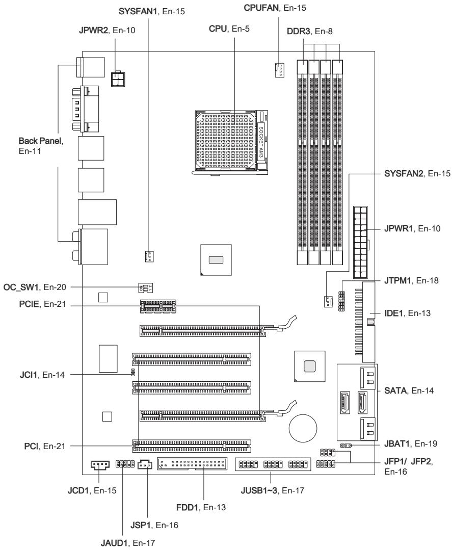
CPU (Central Processing Unit)
When you are installing the CPU, make sure to install the cooler to prevent overheating. If you do not have the CPU cooler, consult your dealer before turning on the computer. For the latest information about CPU, please visit http://www.msi.com/index.php?func=cpuform2
Important
Overheating
Overheating will seriously damage the CPU and system. Always make sure the cooling fan can work properly to protect the CPU from overheating. Make sure that you apply an even layer of thermal paste (or thermal tape) between the CPU and the heatsink to enhance heat dissipation.
Replacing the CPU
While replacing the CPU, always turn off the ATX power supply or unplug the power supply's power cord from the grounded outlet first to ensure the safety of CPU.
Overclocking
This mainboard is designed to support overclocking. However, please make sure your components are able to tolerate such abnormal setting, while doing overclocking. Any attempt to operate beyond product specifications is not recommended. We do not guarantee the damages or risks caused by inadequate operation or beyond product specifications.
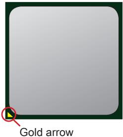
Introduction to AM3 CPU
The surface of CPU. Remember to apply some thermal paste on it for better heat dispersion.
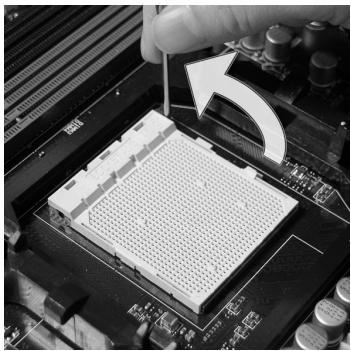
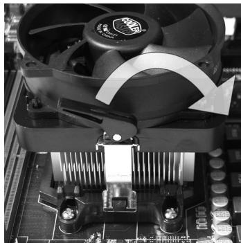
CPU & Cooler Installation
When you are installing the CPU, make sure the CPU has a cooler attached on the top to prevent overheating. Meanwhile, do not forget to apply some thermal paste on CPU before installing the heat sink/cooler fan for better heat dispersion.
Follow the steps below to install the CPU & cooler correctly. Wrong installation will cause the damage of your CPU & mainboard
- Pull the lever sideways away from the socket. Make sure to raise the lever up to a 90-degree angle.
- Look for the gold arrow of the CPU. The gold arrow should point as shown in the picture. The CPU can only fit in the correct orientation.
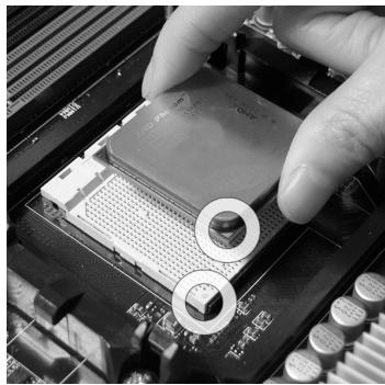
- If the CPU is correctly installed, the pins should be completely embedded into the socket and can not be seen. Please note that any violation of the correct installation procedures may cause permanent damages to your mainboard.
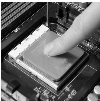
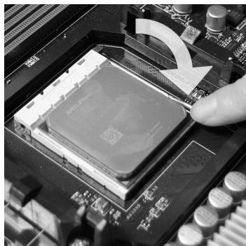
- Press the CPU down firmly into the socket and close the lever. As the CPU is likely to move while the lever is being closed, always close the lever with your fingers pressing tightly on top of the CPU to make sure the CPU is properly and completely embedded into the socket.
- Position the cooling set onto the retention mechanism.
Hook one end of the clip to hook first.
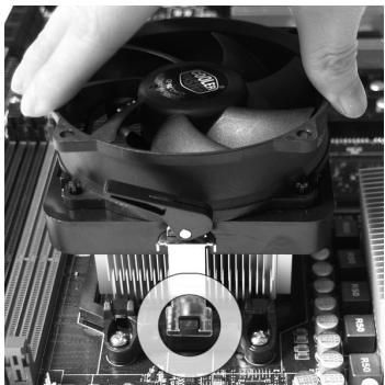
- Fasten down the lever.
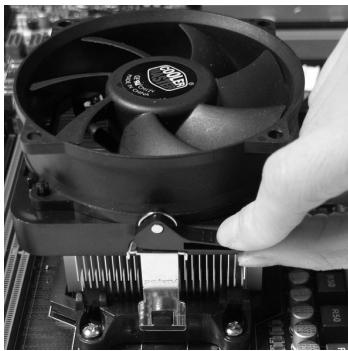
- Then press down the other end of the clip to fasten the cooling set on the top of the retention mechanism.
Locate the Fix Lever and lift up it.

- Attach the CPU Fan cable to the CPU fan connector on the mainboard.
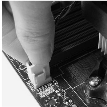
Important
- Mainboard photos shown in this section are for demonstration only. The appearance of your mainboard may vary depending on the model you purchase.
- While disconnecting the Safety Hook from the fixed bolt, it is necessary to keep an eye on your fingers, because once the Safety Hook is disconnected from the fixed bolt, the fixed lever will spring back instantly.
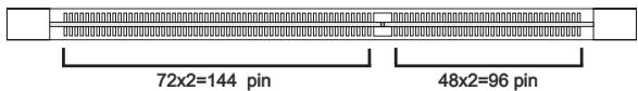
Memory
These DIMM slots are used for installing memory modules. For more information on compatible components, please visit http://www.msi.com/index.php?func=testreport
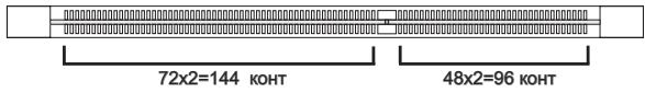
DDR3
240-pin, 1.5V
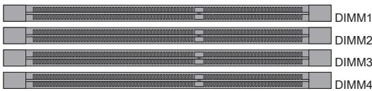
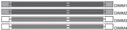
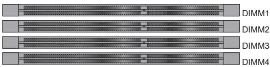
Dual-Channel mode Population Rule
In Dual-Channel mode, the memory modules can transmit and receive data with two data bus lines simultaneously. Enabling Dual-Channel mode can enhance the system performance. The following illustrations explain the population rules for Dual-Channel mode.

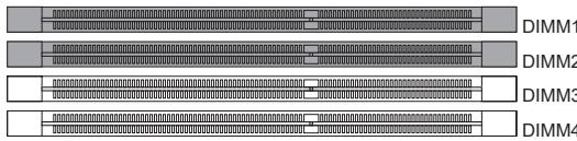

Important
- DDR3 memory modules are not interchangeable with DDR2 and the DDR3 standard is not backwards compatible. You should always install DDR3 memory modules in the DDR3 DIMM slots.
- In Dual-Channel mode, make sure that you install memory modules of the same type and density in different channel DIMM slots.
- To enable successful system boot-up, always insert the memory modules into the DIMM1 first.
- Due to the chipset resource deployment, the system density will only be detected up to 15+GB (not full 16GB) when each DIMM is installed with a 4GB memory module.
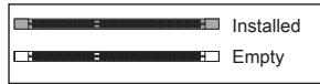
Installing Memory Modules
- The memory module has only one notch on the center and will only fit in the right orientation.
- Insert the memory module vertically into the DIMM slot. Then push it in until the golden finger on the memory module is deeply inserted in the DIMM slot. The plastic clip at each side of the DIMM slot will automatically close when the memory module is properly seated.
- Manually check if the memory module has been locked in place by the DIMM slot clips at the sides.
Important
You can barely see the golden finger if the memory module is properly inserted in the DIMM slot.


Power Supply
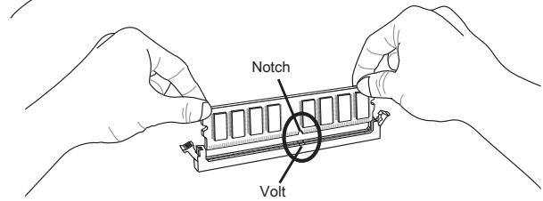
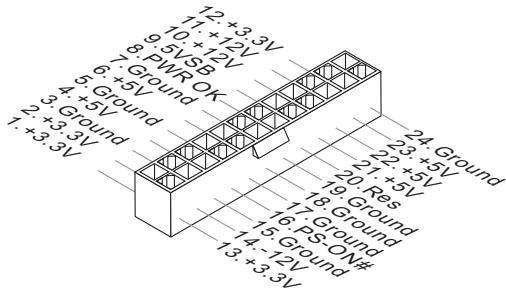
ATX 24-pin Power Connector: JPWR1
This connector allows you to connect an ATX 24-pin power supply. To connect the ATX 24-pin power supply, make sure the plug of the power supply is inserted in the proper orientation and the pins are aligned. Then push down the power supply firmly into the connector.
You may use the 20-pin ATX power supply as you like. If you'd like to use the 20-pin ATX power supply, please plug your power supply along with pin 1 & pin 13.
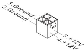
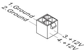
ATX 4-pin Power Connector: JPWR2
This connector is used to provide power to the CPU.
Important
- Make sure that all the connectors are connected to proper ATX power supplies to ensure stable operation of the mainboard.
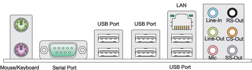
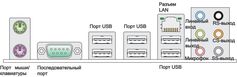
Mouse/Keyboard
The standard PS/2® mouse/keyboard DIN connector is for a PS/2® mouse/keyboard.
Serial Port
The serial port is a 16550A high speed communications port that sends/ receives 16 bytes FIFOs. You can attach a serial mouse or other serial devices directly to the connector.
USB Port
The USB (Universal Serial Bus) port is for attaching USB devices such as keyboard, mouse, or other USB-compatible devices.
LAN
The standard RJ-45 LAN jack is for connection to the Local Area Network (LAN). You can connect a network cable to it.
Yellow
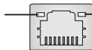
Green/Orange
| LED | Color | LED State | Condition |
| Left | Yellow | Off | LAN link is NOT established. |
| On(Steady state) | LAN link is established. | ||
| On(brighter & pulsing) | The computer is communicating with another computer on the LAN. | ||
| Right | Green | Off | 10 Mbits/sec data rate is selected. |
| On | 100 Mbits/sec data rate is selected. | ||
| Orange | On | 1000 Mbits/sec data rate is selected. |
Audio Ports
These audio connectors are used for audio devices. It is easy to differentiate between audio effects according to the color of audio jacks.
- Line-In (Blue) - Line In, is used for external CD player, tape-player or other audio devices.
Line-Out (Green) - Line Out, is a connector for speakers or headphones. - Mic (Pink) - Mic, is a connector for microphones.
RS-Out (Black) - Rear-Surround Out in 4/5.1/7.1 channel mode.
CS-Out (Orange) - Center/ Subwoofer Out in 5.1/ 7.1 channel mode.
SS-Out (Gray) - Side-Surround Out 7.1 channel mode.
Connectors
Floppy Disk Drive Connector: FDD1
This connector supports 360 KB, 720 KB, 1.2 MB, 1.44 MB or 2.88 MB floppy disk drive.
* The MB layout in this figure is for reference only.
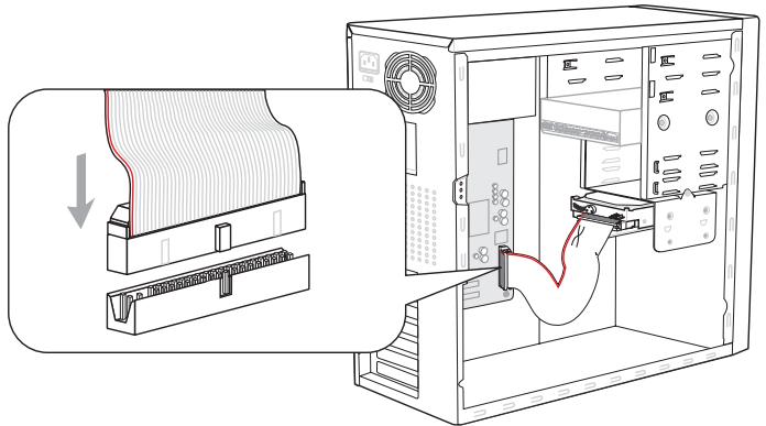
IDE Connector: IDE1
This connector supports IDE hard disk drives, optical disk drives and other IDE devices.
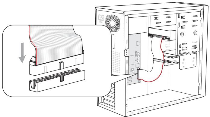
* The MB layout in this figure is for reference only.
Important
If you install two IDE devices on the same cable, you must configure the drives separately to master / slave mode by setting jumpers. Refer to IDE device's documentation supplied by the vendors for jumper setting instructions.
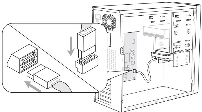
Serial ATA Connector: SATA1~6
This connector is a high-speed Serial ATA interface port. Each connector can connect to one Serial ATA device.

* The MB layout in this figure is for reference only.
Important
Please do not fold the Serial ATA cable into 90-degree angle. Otherwise, data loss may occur during transmission.
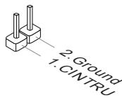
Chassis Intrusion Connector: JCI1
This connector connects to the chassis intrusion switch cable. If the chassis is opened, the chassis intrusion mechanism will be activated. The system will record this status and show a warning message on the screen. To clear the warning, you must enter the BIOS utility and clear the record.

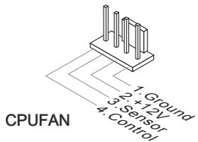
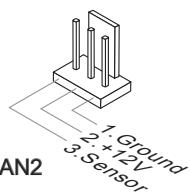
Fan Power Connectors: CPUFAN, SYSFAN1, SYSFAN2
The fan power connectors support system cooling fan with +12V . When connecting the wire to the connectors, always note that the red wire is the positive and should be connected to the +12V ; the black wire is Ground and should be connected to GND. If the mainboard has a System Hardware Monitor chipset on-board, you must use a specially designed fan with speed sensor to take advantage of the CPU fan control.
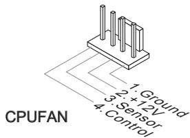
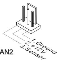
SYSFAN1/ SYSFAN2
Important
- Please refer to the recommended CPU fans at processor's official website or consult the vendors for proper CPU cooling fan.
- CPUFAN supports fan control. You can install Overclocking Center utility that will automatically control the CPU fan speed according to the actual CPU temperature.
- Fan cooler set with 3 or 4 pins power connector are both available for CPUFAN.
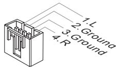
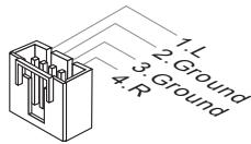
CD-In Connector: JCD1
This connector is provided for external audio input.
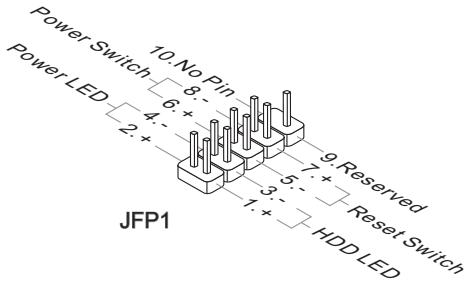
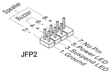
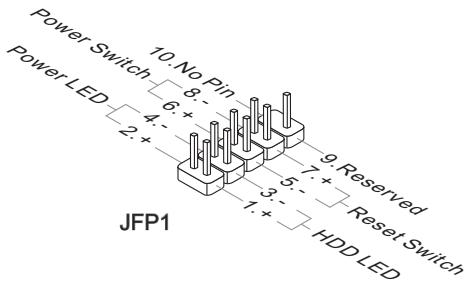
Front Panel Connectors: JFP1, JFP2
These connectors are for electrical connection to the front panel switches and LEDs. The JFP1 is compliant with Intel® Front Panel I/O Connectivity Design Guide.
S/PDIF-Out Connector: JSP1
This connector is used to connect S/PDIF (Sony & Philips Digital Interconnect Format) interface for digital audio transmission.
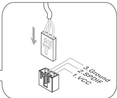
* The MB layout in this figure is for reference only.
S/PDIF-Out Bracket (optional)
Front USB Connector: JUSB1 / JUSB2 / JUSB3
This connector, compliant with Intel® I/O Connectivity Design Guide, is ideal for connecting high-speed USB interface peripherals such as USB HDD, digital cameras, MP3 players, printers, modems and the like.
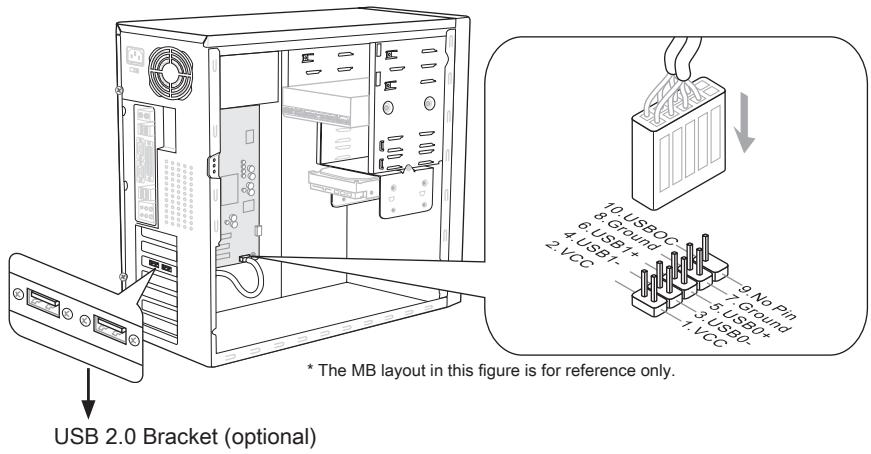
Important
Note that the pins of VCC and GND must be connected correctly to avoid possible damage.
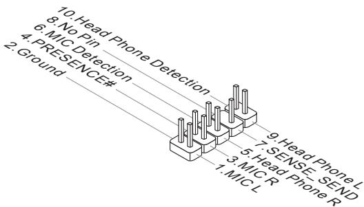
Front Panel Audio Connector: JAUD1
This connector allows you to connect the front panel audio and is compliant with Intel® Front Panel I/O Connectivity Design Guide.
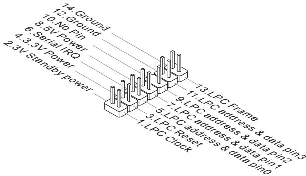
TPM Module connector: JTPM1
This connector connects to a TPM (Trusted Platform Module) module (optional). Please refer to the TPM security platform manual for more details and usages.

Jumpers
Clear CMOS Jumper: JBAT1
There is a CMOS RAM onboard that has a power supply from an external battery to keep the data of system configuration. With the CMOS RAM, the system can automatically boot OS every time it is turned on. If you want to clear the system configuration, set the jumper to clear data.

JBAT1

Keep Data

Clear Data
Important
You can clear CMOS by shorting 2-3 pin while the system is off. Then return to 1-2 pin position. Avoid clearing the CMOS while the system is on; it will damage the mainboard.
Switch
This mainland provides the following switch for you to set the computer's function. This section will explain how to change your mainland's function through the use of switch.
Easy OC Switch: OC_SW1
You can overclock the FSB to increase the processor frequency by changing the switch. Follow the instructions below to set the FSB.

Default

Increase 10% speed of FSB

Increase 15% speed of FSB

Increase 20% speed of FSB
Important
- Make sure that you power off the system before setting the switch.
- When overclocking cause system instability or crash during boot. Please set the switch to default setting.
Slots
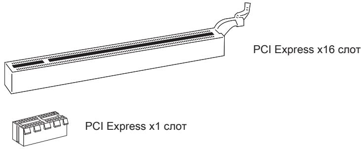
PCIE (Peripheral Component Interconnect Express) Slot
The PCI Express slot supports the PCI Express interface expansion card.
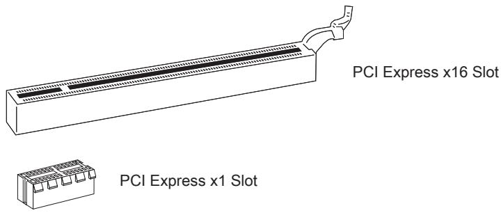
PCI (Peripheral Component Interconnect) Slot
The PCI slot supports LAN card, SCSI card, USB card, and other add-on cards that comply with PCI specifications.
32-bit PCI Slot
Important
When adding or removing expansion cards, make sure that you unplug the power supply first. Meanwhile, read the documentation for the expansion card to configure any necessary hardware or software settings for the expansion card, such as jumpers, switches or BIOS configuration.
PCI Interrupt Request Routing
The IRQ, acronym of interrupt request line and pronounced I-R-Q, are hardware lines over which devices can send interrupt signals to the microprocessor. The PCI IRQ pins are typically connected to the PCI bus pins as follows:
| Order1 | Order2 | Order3 | Order4 | |
| PCI Slot1 | INT E# | INT F# | INT G# | INT H# |
| PCI Slot2 | INT F# | INT G# | INT H# | INT E# |
| PCI Slot3 | INT G# | INT H# | INT E# | INT F# |
ATI CrossFireX™ (Multi-GPU) Technology
ATI CrossFireX™ is the ultimate multi-GPU performance gaming platform. Enabling game-dominating power, ATI CrossFireX™ technology enables two or more discrete graphics processors to work together to improve system performance. ATI CrossFireX™ technology allows you to expand your system's graphics capabilities. It allows you the ability to scale your system's graphics horsepower as you need it, supporting two or more ATI Radeon™ HD graphics cards, making this the most scalable gaming platform ever. The mainboard can auto detect the CrossFireX™ mode by software, therefore you don't have to enable the CrossFireX™ in BIOS by yourself. The following details the 2-way CrossFireX™ installation.
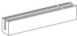
- Install two ATI Radeon™ HD graphics card into two PCIE x16 slots.
- With two cards installed, an CrossFire™ Video Link cable is required to connect the golden fingers on the top of these two graphics cards (refer to the picture below). Please note that although you have installed two or more graphics cards, only the video outputs on the graphics card installed in first PCIE x16 will work. Hence, you only need to connect a monitor to this graphics card.

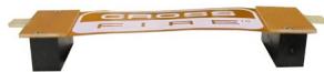
CrossFireX™ Video Link cable
Important
- Mainboard photos shown in this section are for demonstration only. The appearance of your motherboard may vary depending on the model you purchase.
- If you intend to install TWO graphics cards for CrossFire™ mode, make sure that: a. these two graphics cards are of the same brand and specifications; b. these two cards are installed on both mazarine PCIE x16 slots.
- Make sure that you connect an adequate power supply to the power connector on the graphics card to ensure stable operation of the graphics card.
-
Only Windows®XP with Service Pack 2 (SP2)& Windows®XP Professional x64 Edition & Windows®Vista & Windows®7 support the CrossFire™ function.
-
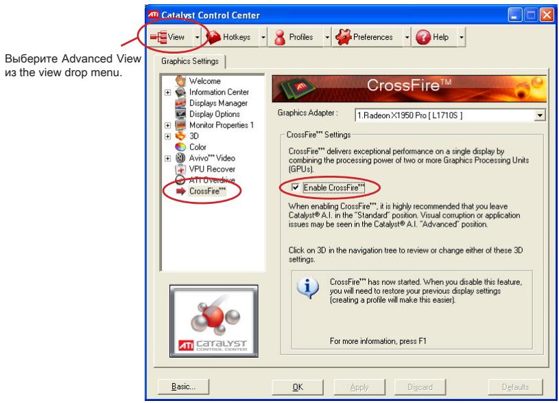
When all of the hardware and software has been properly set up and installed, reboot the system. After entering the O.S., click the "Catalyst™ Control Center" icon on the desktop. There is a setting in the Catalyst™ Control Center that needs to be enabled for CrossFire™ to operate. The following aspect appears in Catalyst™ Control Center:
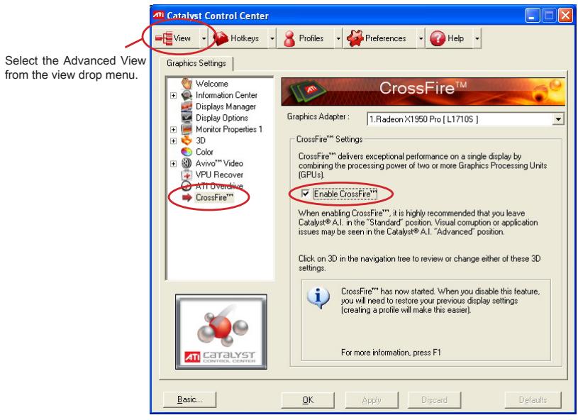
Important
A CrossFireX™ system has four possible display modes:
SuperTiling
- Scissor Mode
Alternate Frame Rendering
Super Anti-aliasing.
for more details, please consult the graphics card manual from the manufacturer.
LED Status Indicators
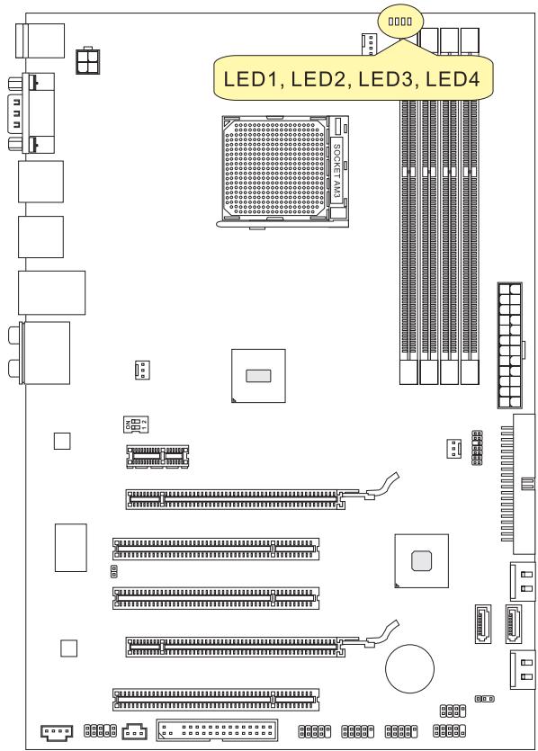
CPU Phase LEDs: LED1, LED2, LED3, LED4
These LEDs indicate the current CPU power phase mode. Follow the instructions below to read.
Blue light
Off
| LED1 | LED2 | LED3 | LED4 | Mode |
| ■ | □ | □ | □ | CPU is in 1 phase power mode. |
| ■ | ■ | ■ | ■ | CPU is in 4 phase power mode. |
BIOS Setup
This chapter provides basic information on the BIOS Setup program and allows you to configure the system for optimum use. You may need to run the Setup program when:
- An error message appears on the screen during the system booting up, and requests you to run BIOS SETUP.
You want to change the default settings for customized features.
Important
- The items under each BIOS category described in this chapter are under continuous update for better system performance. Therefore, the description may be slightly different from the latest BIOS and should be held for reference only.
- Upon boot-up, the 1st line appearing after the memory count is the BIOS version. It is usually in the format:
A7599AMS V10.X 051010 where:
1st digit refers to BIOS maker as A = AMI , W = AWARD , and P = PHOENIX . 2nd - 5th digit refers to the model number.
6th digit refers to the chipset as I = Intel, N = NVIDIA, A = AMD and V = VIA.
7th - 8th digit refers to the customer as MS = all standard customers.
V10.X refers to the BIOS version.
051010 refers to the date this BIOS was released.
Entering Setup
Power on the computer and the system will start POST (Power On Self Test) process. When the message below appears on the screen, press key to enter Setup.
Press DEL to enter SETUP
If the message disappears before you respond and you still wish to enter Setup, restart the system by turning it OFF and On or pressing the RESET button. You may also restart the system by simultaneously pressing
Getting Help
After entering the Setup menu, the first menu you will see is the Main Menu.
Main Menu
The main menu lists the setup functions you can make changes to. You can use the arrow keys (↑↓) to select the item. The on-line description of the highlighted setup function is displayed at the bottom of the screen.
Sub-Menu
If you find a right pointer symbol appears to the left of certain fields that means a submenu can be launched from this field. A sub-menu contains additional options for a field parameter. You can use arrow keys (↑↓) to highlight the field and press
The BIOS setup program provides a General Help screen. You can call up this screen from any menu by simply pressing <F1> . The Help screen lists the appropriate keys to use and the possible selections for the highlighted item. Press <Esc> to exit the Help screen.
The Main Menu
Once you enter BIOS CMOS Setup Utility, the Main Menu will appear on the screen. The Main Menu allows you to select from the setup functions and two exit choices. Use arrow keys to select among the items and press
| Standard CMOS Features | Cell Menu |
| Advanced BIOS Features | M-Flash |
| Integrated Peripherals | Overclocking Profile |
| Power Management Setup | Load Fail-Safe Defaults |
| H/W Monitor | Load Optimized Defaults |
| Green Power | Save & Exit Setup |
| BIOS Setting Password | Exit Without Saving |
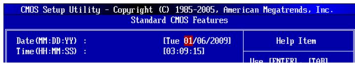
Standard CMOS Features
Use this menu for basic system configurations, such as time, date etc.
Advanced BIOS Features
Use this menu to setup the items of the BIOS special enhanced features.
Integrated Peripherals
Use this menu to specify your settings for integrated peripherals.
Power Management Setup
Use this menu to specify your settings for power management.
H/W Monitor
This entry shows your PC health status.
Green Power
Use this menu to specify the power phase.
BIOS Setting Password
Use this menu to set the password for BIOS.
Cell Menu
Use this menu to specify your settings for frequency/voltage control and overclocking.
M-Flash
Use this menu to read/ flash (or backup) the BIOS from (to) storage drive (FAT/ FAT32 format only).
Overclocking Profile
Use this menu to save/ load your settings to/ from CMOS for BIOS.
Load Fail-Safe Defaults
Use this menu to load the default values set by the BIOS vendor for stable system performance.
Load Optimized Defaults
Use this menu to load the default values set by the mainboard manufacturer specifically for optimal performance of the mainboard.
Save & Exit Setup
Save changes to CMOS and exit setup.
Exit Without Saving
Abandon all changes and exit setup.
When enter the BIOS Setup utility, follow the processes below for general use.
- Load Optimized Defaults: Use control keys ( ) to highlight the Load Optimized Defaults field and press < Enter>, a message as below appears:
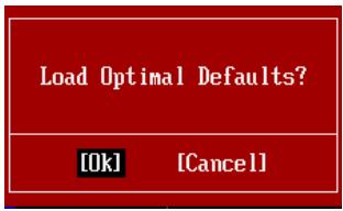
Select [Ok] and press Enter to load the default settings for optimal system performance.
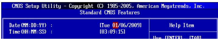
- Setup Date/ Time : Select the Standard CMOS Features and press
to enter the Standard CMOS Features-menu. Adjust the Date, Time fields.
- Save & Exit Setup: Use control keys ( ) to highlight the Save & Exit Setup field and press
, a message as below appears:

Select [Ok] and press Enter to save the configurations and exit BIOS Setup utility.
Important
The configuration above are for general use only. If you need the detailed settings of BIOS, please see the English manual on MSI website.
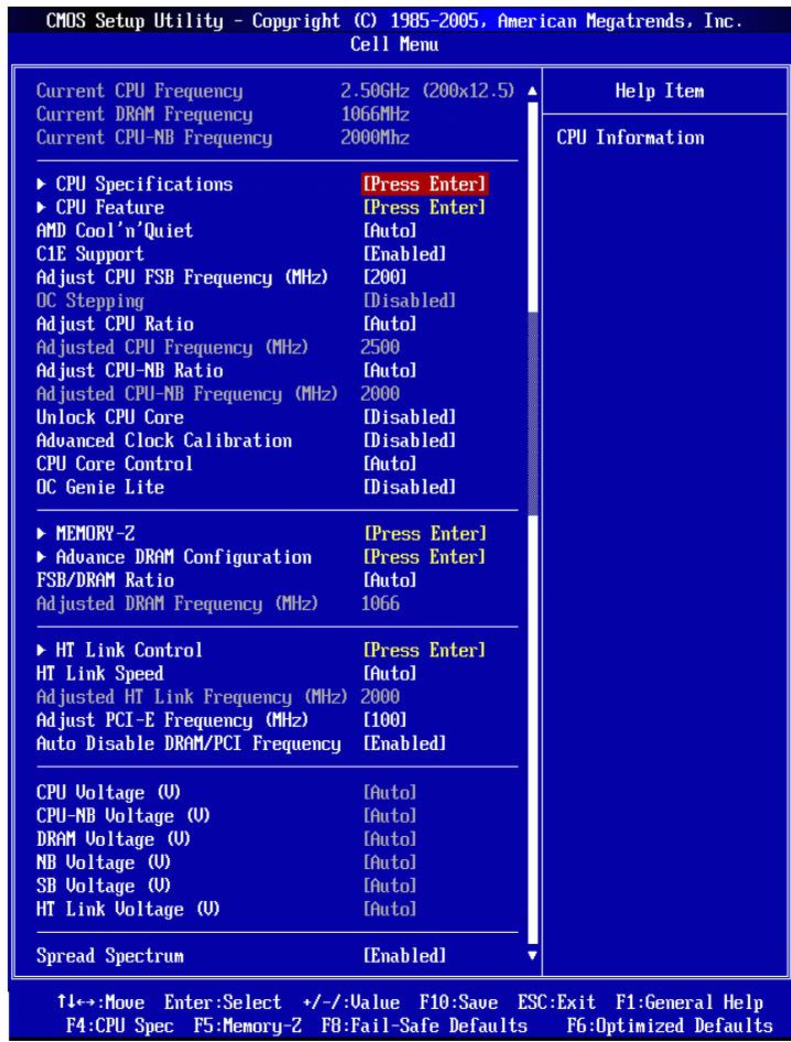
- Cell Menu Introduction : This menu is for advanced user who want to overclock the mainboard.
Important
Change these settings only if you are familiar with the chipset.
Current CPU/DRAM/CPU-NB Frequency
These items show the current clocks of CPU/ Memory & CPU-NB speed. Read-only.
CPU Specifications
Press
CPU Technology Support
Press
CPU Feature
Press
AMD Cool'n'Quiet
The Cool'n'Quiet technology can effectively and dynamically lower CPU speed and power consumption.
Important
To ensure that Cool'n'Quiet function is activated and will be working properly, it is required to double confirm that:
- Run BIOS Setup, and select Cell Menu. Under Cell Menu, find AMD Cool'n'Quiet, and set this item to "Enabled".
- Enter Windows, and select [Start]->[Settings]->[Control Panel]->[Power Options]. Enter Power Options Properties tag, and select Minimal Power Management under Power schemes.
C1E Support
To enable this item to read the CPU power consumption while idle. Not all processors support Enhanced Halt state (C1E).
SVM Support
This item is used to enable/ disable SVM.
AMD Cool'n'Quiet
The Cool'n'Quiet technology can effectively and dynamically lower CPU speed and power consumption.
C1E Support
To enable this item to read the CPU power consumption while idle. Not all processors support Enhanced Halt state (C1E).
Adjust CPU FSB Frequency (MHz)
This item allows you to select the CPU Front Side Bus clock frequency (in MHz).
OC Stepping
This item will be enabled after you set the overclocking frequency in the "Adjust CPU FSB Frequency (MHz)". And the following items will appear. This items will help the system to overclock step by step after system booting up.
Start OC Stepping From (MHz)
This item is used to set the initial FSB clock. The system will boot with the initial FSB clock, and start to overclock from initial FSB clock to set FSB clock that you set in "Adjust CPU Base Frequency (MHz)" step by step.
OC Step
This item is used to set how many steps for FSB colck overclocking.
OC Step Count Timer
This item is used to set the buffer time for every step.
Adjust CPU Ratio
This item is used to adjust CPU clock multiplier (ratio). It is available only when the processor supports this function.
Adjusted CPU Frequency (MHz)
It shows the adjusted CPU frequency. Read-only.
Adjust CPU-NB Ratio
This item is used to adjust CPU-NB ratio.
Adjusted CPU-NB Frequency (MHz)
It shows the adjusted CPU-NB frequency. Read-only.
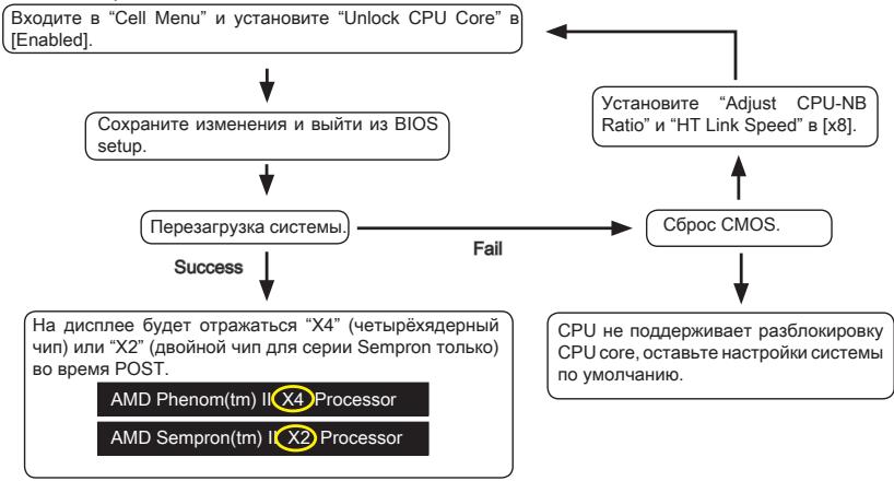
Unlock CPU Core
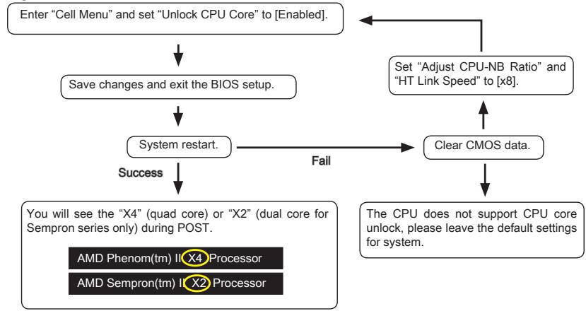
This item is used to unlock the CPU core. Please refer to the procedures below for CPU core unlocked in BIOS setup.
Important
- This CPU core unlocked behavior depends on the CPU ability/ characteristic, and it is not guaranteed.
- Depend on CPU's characteristic, once you get instable scenario, please restore the default settings for system.
- You can also check the core numbers in performance tab of Windows task manager.
Advanced Clock Calibration
This item is for overclock. Setting to [Enabled] allows you to set the CPU Ratio higher. It is available only when the processor supports this function.
CPU Core Control
This item is used to control number of CPU cores. When set to [Auto], the CPU will operate under the default number of cores. When set to [Manual], you will be able to enable/disable the specific CPU core.
Core 1/2/3/4
These items are used to enable/disable the core 1/2/3/4.
OC Genie Lite
Setting this item to [Enabled] allows the system to detect the maximum FSB clock and to overclock automatically. If overclocking fails to run, you can try the lower FSB clock for overclocking successfully.
MEMORY-Z
Press
DIMM1~4 Memory SPD Information
Press
Advance DRAM Configuration
Press
DRAM Timing Mode
This field has the capacity to automatically detect all of the DRAM timing.
DRAM Drive Strength
This item allows you to control the memory data bus' signal strength. Increasing the drive strength of the memory bus can increase stability during overclocking.
DRAM Advance Control
This field has the capacity to automatically detect the advanced DRAM timing.
1T/2TMemory Timing
This item controls the SDRAM command rate. Select [1T] makes SDRAM signal controller to run at 1T (T=clock cycles) rate. Selecting [2T] makes SDRAM signal controller run at 2T rate.
DCT Unganged Mode
This feature is used to Integrate two 64-bit DCTs into a 128-bit interface.
Bank Interleaving
Bank Interleaving is an important parameter for improving overlapping capability of memory. It allows system to access multiple banks simultaneously.
Power Down Enable
This is a memory power-saving technology. When the system does not access memory over a period of time, it will automatically reduce the memory power supply.
MemCik Tristate C3/ATLVID
This setting allows you to enable/disable the MemClk Tristating during C3 and ATLVID.
FSB/DRAM Ratio
This item allows you to select the ratio of FSB/ DRAM.
Adjusted DRAM Frequency (MHz)
It shows the adjusted Memory frequency. Read-only.
HT Link Control
Press
HT Incoming/Outgoing Link Width
These items allow you to set the Hyper-Transport Link width. Setting to [Auto], the system will detect the HT link width automatically.
HT Link Speed
This item allows you to set the Hyper-Transport Link speed. Setting to [Auto], the system will detect the HT link speed automatically.
Adjusted HT Link Frequency (MHz)
It shows the adjusted HT Link frequency. Read-only.
Adjust PCI-E Frequency (MHz)
This field allows you to select the PCIE frequency (in MHz).
Auto Disable DRAM/PCI Frequency
When set to [Enabled], the system will remove (turn off) clocks from empty DRAM/PCI slots to minimize the electromagnetic interference (EMI).
- CPU Voltage (V)/ CPU-NB Voltage (V)/ DRAM Voltage (V)/ NB Voltage (V)/ SB Voltage (V)/ HT Link Voltage (V)
These items are used to adjust the voltage of CPU, Memory and chipset.
Spread Spectrum
When the mainboard's clock generator pulses, the extreme values (spikes) of the pulses create EMI (Electromagnetic Interference). The Spread Spectrum function reduces the EMI generated by modulating the pulses so that the spikes of the pulses are reduced to flatter curves.
Important
- If you do not have any EMI problem, leave the setting at [Disabled] for optimal system stability and performance. But if you are plagued by EMI, select the value of Spread Spectrum for EMI reduction.
- The greater the Spread Spectrum value is, the greater the EMI is reduced, and the system will become less stable. For the most suitable Spread Spectrum value, please consult your local EMI regulation.
- Remember to disable Spread Spectrum if you are overclocking because even a slight jitter can introduce a temporary boost in clock speed which may just cause your overclocked processor to lock up.
Software Information
Take out the Driver/Utility DVD that is included in the mainboard package, and place it into the DVD-ROM drive. The installation will auto-run, simply click the driver or utility and follow the pop-up screen to complete the installation. The Driver/Utility DVD contains the:
- Driver menu : The Driver menu shows the available drivers. Install the driver by your desire and to activate the device.
- Utility menu : The Utility menu shows the software applications that the mainboard supports.
Important
Please visit the MSI website to get the latest drivers and BIOS for better system performance.

Deutsch
870-G45 Serie
Spezifikationen
Prozessoren
SuperTiling
- Scissor Mode
Alternate Frame Rendering
Super Anti-aliasing.
Press DEL to enter SETUP
| Standard CMOS Features | Cell Menu |
| Advanced BIOS Features | M-Flash |
| Integrated Peripherals | Overclocking Profile |
| Power Management Setup | Load Fail-Safe Defaults |
| H/W Monitor | Load Optimized Defaults |
| Green Power | Save & Exit Setup |
| BIOS Setting Password | Exit Without Saving |
Integrated Peripherals
BIOS Setting Password
Overclocking Profile
Current CPU/DRAM/CPU-NB Frequency
CPU Technology Support
Adjust CPU FSB Frequency (MHz)
Start OC Stepping From (MHz)
Advanced Clock Calibration
Adjusted DRAM Frequency (MHz)
HT Incoming/Outgoing Link Width
Adjusted HT Link Frequency (MHz)
Adjust PCI-E Frequency (MHz)
- CPU Voltage (V)/CPU-NB Voltage (V)/DRAM Voltage (V)/NB Voltage (V)/SB Voltage (V)/HT Link Voltage (V)
Emplacement PCIE (Peripheral Component Interconnect Express)
Emplacement PCI (Peripheral Component Interconnect)
SuperTiling
- Scissor Mode
Alternate Frame Rendering
Super Anti-aliasing.
CPU Phase LEDs : LED1, LED2, LED3, LED4
Press DEL to enter SETUP
| Standard CMOS Features | Cell Menu |
| Advanced BIOS Features | M-Flash |
| Integrated Peripherals | Overclocking Profile |
| Power Management Setup | Load Fail-Safe Defaults |
| H/W Monitor | Load Optimized Defaults |
| Green Power | Save & Exit Setup |
| BIOS Setting Password | Exit Without Saving |
Standard CMOS Features (Fonctions CMOS standard)
Current CPU/DRAM/CPU-NB Frequency
CPU Technology Support
Adjust CPU FSB Frequency (MHz)
Start OC Stepping From (MHz)
Adjusted CPU Frequency (MHz)
Adjusted CPU-NB Frequency (MHz)
Advanced Clock Calibration
Adjusted DRAM Frequency (MHz)
HT Incoming/Outgoing Link Width
Adjusted HT Link Frequency (MHz)
Adjust PCI-E Frequency (MHz)
CPU Voltage (V)/CPU-NB Voltage (V)/DRAM Voltage (V)/NB Voltage (V/ SB Voltage (V)/ HT Link Voltage (V)
Pa3MeueHne KOMNoHEtOB CnCTeMHoN PJIaTbI

CPU (LêntpaJbHbI npoceccop)
Pn yctaHOBKe CPU, uTo6bI y6peey npoecccop ot nepereBa, He 3a6yDbTe yCTaHOBt npoecccophny KJyep. EcnNy Bac HET npoecccopHoro KJyepa, nojkayncta, CBxKNTecb C dInepom C cIeblIO npio6peTeHn I erO yCTaHOBKn Do TORO, KaK BkIIOuHTe KOMNbHTep.
- 3aTeM haxmnte Ha dpyroI kpaI, yTo6bl yCTaHOBnTb paDnatOp Ha y3en KpenJIeHnIy. HauNTe pbUar fHKcaunn I NOHNMIte erO.
- ПоdkночиTe Ka6eJIb BeHTnIЯTopa CPU K COOTBeTCTByUOuEMy pa3bemy CnCTeMHoI PnAToBl.

BhimhaHne
- FOToRpaФnN CnCTeMHo NnAToB B 3ToM pa3DJIe NpUBeDEHbI TOnbKO nIaI DEMOHcTpaCm. BHeuHn BnD BaSei MoDeHn MoKeT OTnNuHaTcR O T npUBeDeHHO 3deCb.
- Пи OTcoeHHeHnФИКсPyUоJero pIyAra Heo6xOДmO co6JIoudaTb OcTOPOxHOCtB,Тak KAKpbIyarNoIpyKuHEn I npI OTnyCKaHn OH BepHETcC NcXoJHOneNoIoxKeHne.
NamrTa
CnoTb DIMM nCnOJb3yIOTcI yCTaHOBKn MOyIe NAMrTn. 3a DOnONHHTeJIbHOINHΦoPmaIeN O COBmecTmblx KOMNoHEHTax ObpaTntEc b Ha caIT
http://www.msi.com/index.php?func testreport
DDR3
240-KoHT, 1.5V
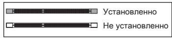
IpaBnla yCTaHOBKn MoUyIe NpAmrTn Ipn pa60tbl B DByXkHaJIbHOM pexmme
B DbyxkaHaIbHom pexime MoDyIi naMRT MOrY T nepeDaBaT I npHIMaTb daHHbe no 2 uHAm oNHOBpeMeHNo. Ppi nCpOJIb3OBAHH IN DByxkaHaJIbHO r peXIma npOn3BOJNTeJIbHOCTb CnCTeMbI NOBIIaETcR. HIXe pINBeJeHbI npABIna 3aONHeHr cIOTOB NaMRTI dIpaBoTb B DByxkaHaJIbHOM pexime.
①
(2)
BhimhaHue
- Moунн DDR3 He B3aHmO3aMeHЯeMbI c MoулЯmN DDR2, И стандг T DDR3 He Umeet obpaTHoN COBmecTmocTn. CneJyET BCeRda yctaHaBnBaTb Moул n lamrTn DDR3В pa3bEmbl DDR3 DIMM.
-Дя pa6obTb I BdByXkaHaJIbHOM pexIme y6eJntEcB,чTO B pa3beMax pa3HbIX KaHaJIIOB y Bac yCTaHOBJIeHbI MOdyI IN ODHORO TUNA IN ODNHaKOBOE MKOCTN. - TTo6bI CnTeMa 3aRpy3uNlaCb, BNaJaIe yCTaHOBuTte MoDyInB pa3bEm DIMM1.
- 13-3a cneuФнк npacpeIeHnIcNCTMhIx pecypcoB YIncTeA, obEIM IOCTynHOI pAMrTO MOKeT MAKcMAmIbHO COCTaBtB 15+ΓB (Ho He 16ΓB) npi yctaHOBKe MoDyNeI pAMrTo 4ΓB B KAKdIb N3 CNOTOB.
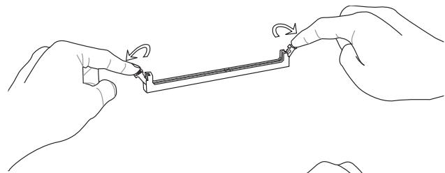
YCTaHOBka MOyJeI pAmrTn
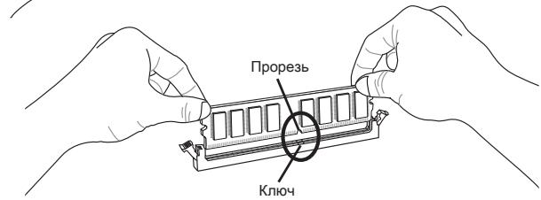
- MoDyIi namrTn HmEOT OHy npOpe3b B cpeHne YactN. MoDyIb BOYIDet B pa3beM ToIbKO pRn IpaBnIbHOJ opNEHTaun.
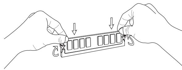
- BCTaBbTe MoDyIb B DIMM cnot B BePtnKaJIbHOM HnPaBHeHn. 3aTeM HaxMtte Ha Hero, yTo6bl 30JOnueHbIe KOHTaKbTI rIy6Oko nOrpy3uInc b DIMM cnot. Ecnn MOyIb pAmrTn BCTaBNeH npaBnIbHO, To INaCTIKOBbIe 3aUeJIKN Ha o6oN X KOHcX 3akpoIOTc ABTomaTUnCeKn.
- BpyuHyU y6eIITecb, yTO MoDyIb 3aKpeIJIeN B CJIoTe DIMM 3aUeIKNaMn c o6eHX CTOpOH.
BhimaHue
30JIOIe KOHTaKtbl eDBA BnHbI, ecNI MOyJIIN nAmrTn npaBnIbHO pa3MeueHbIB DIMM cnot.
Pa3bem nITaHnA
24-KoHTaKTbIpa3bEMnTAnHrATX:JPWR1
3TOT pa3bem NO3BONJET NOKNIQUHTb 24-KOHTAKTHbI KOHKeTOp NITaHnA TX.ДЯ ERo NOKJIQUChENy y6eINTEcB, YTO KOHKeTOp I KOHTaKTbI pa3bema npabNtHo copHeHTnpOBaHbI. 3aTeM NIOTHO BCTaBbTe ERO B pa3bem HA CNTeMHOn PnATE.
BbI TaKke MoKTe NcNoJIb3OBAtB 20-KoHTaKTHbIy ATX 6nok nTahnI. PpN IcNoJIb3OBAHmN 20-KoHTaKTHOro pa3beMa, NOdKJIouaYte erO BDoJI bKOHTaKToB 1 n 13.
4-KoHTaKTHbI pa3bem nHTaHmA TX: JPWR2
3TOT pa3bem nHTaHnI NCNoJIb3yETc dIy oBecneueHnI nHTaHn Ipoceccopa.
BHTMAHHE
- Y6eHntecb B TOM,чTo BCE pa3bEmbl NOdknOueHbI K NCTOChHKam NtAHHA ATX dJa CtaBnJbHOi pa60Tb CiTeMHoI PJIaTbI.
Порт мыши/клавиatypebl
CtAnIapThbIe pa3bEmbl DIN PS/2® Дпя подкюченя МblSiN/KJIaBnAtypbl c nHTepdEiCom PS/2®.
Посnéобателови порт
Даннь pa3bem АВЛЯЕТСВ ВICOKOCKOPOCTHbIM NOCPeIDOBaTeJIbHbIM NOPTom CB73N 16550A c 16-6aHTHOI nepeDAyeF FIFO. K 3ToMy pa3bemy MOxHNo HeIOcpeIcTBeHHO noIKNHHTb NOCPeIDOBaTeJIbHOE yCTpoiCTBO.
Noprt USB
USB nopT (Universal Serial Bus) no3B0JЯET noДКЛЮЧаТ takne USB yctpoiCTBa, кak KlaBnaTpa, Мblши T.D.
Pa3bem LAN
CtanhapTbI pa3bem RJ-45 dIy noiknueHnK Iokalho BvIuNCInTeJbHO Cetn (LAN). K hemy noiknouOaTc Ka6eJIb lokaHbHO cETn.

* KomnoentbI cyTeMHOI IIaTbI B 306paKeHN TOnBko DnA CnpaBKn.
BhimaHue
U36eaiTe, noKanyiSta, pe3Knx u3rN6OB Kabena Serial ATA. B npotnbom cnyuae MOryT Bo3HnKHyTb nOtepnu daHHbIX npu nepedaue.
Pa3bEm DaTUnKa OTKpbBaHnK Kopnyca: JCI1
K 3TOMy KOHNHeKToPnyoKnHouaetcKa6eIb DaTuNka, yCTaHOBneHHoro B Kopnyce. PnO tKpbIBaHm KOpNyca erO MexAHn3M aKTNB3npyETc. CnCTema 3aONMHaet 3TO c6bItne N BbIaet npeDynpexJdeHne Ha ekpaH. PpeDynpexJdeHne MOxHO OTKJIooHTb B HacTpOikax BIOS.
Pazbem nitaHnBentnoTOpOB:CPUFAN, SYSFAN1, SYSFAN2
Pa3bEmblNTaHnBEHTNlIaTOPOB NOdepKnaBaHT BeHTNlaTOpb c nTaHem +12B.
Ppi NpOKnIOueHmne Heo6xOaHMO pOMHnTB, yTO KpaChbI IPOBOID NpOKnIOuAeTCK 5HNHe +12B, YepHbI - K 3emJIe GND. Ecnn Ha CnCTeMHo IINaTe yCTaHOBJeHa MkPoCxema annapaTHoro MOHToPunHra, Heo6xOaHMO nCNoJb3ObaT bCneuaJIbHbe BEHTNlaTOpb c DaTuNKamM CKOpocT dJa peaIn3aUcn FyHKUIN UnpaBLeHna BEHTNlaTOpAMN.
SYSFAN1/ SYSFAN2
BHTMAHHE
- 4To6bI y3HaTb O moDeIaX IOxOJaXuX BeHTnIaTOPOB, o6paTInTeCb, noKaIyIcTa, Ha OΦnIaJIbHbI Be6 caNT nII npOKOHcyIbTnpUyTECb c npOdaIOM.
- CPUFAN noДержиBaet упаьнения скорocью врашиета В entиятopa. Длг abTomatчeckoro kontrponla скорoctи BeHTnIЯтopa npoueccopa, 3abnciшу OT TemпepaTypыnpоцeccopa И сntembl, можно установи Overclocking Center.
- Pa3bem CPUFAN noДeprKnBaET BeHTnJIaTOpbl, KaK c 3, TaK n c 4 KoTHaKTaMn.
Pa3bem CD-In: JCD1
3TOT KOHHeKToP npEHa3HaueH dIy nOdknIOueHn BHeHrero BxOda ayDIO.
KoHneKToPbI nepeDHeN paHeN: JFP1, JFP2
3TN KOHHeKTopbI NcNoJIb3yIOTcI dIa NIOKIIIOUeHnI KHOJOK I INHdIKaTOpOB, paCNOJoxeHHbIX Ha nepeDneI naHeIi Kopnyca. KOHHeKTop JFP1 COOTBeTCTByET pykoBoIDCTBy Intel® Front Panel I/O Connectivity Design.

Pazem S/PDIF-Out: JSP1

CkopoocTb FSB NOBblIaetcna 15%

Ckopoctb FSB NOBbIaetcna 20%
BhimaHne
Cnot PCIE (Peripheral Component Interconnect Express)
CnotPCIExpressnoДеркиBaetKapTbIpaSUnpeHnIHTepSeiCaPCIExpress.
Cnot PCI (Peripheral Component Interconnect)
Cnot PCI no3Bnonraret yctahOBnTB kapTb LAN, SCSI, USB and pyrme dononHnTeNbHbIe KapTb paacnpeHnra, KOtOpbie coOTBetCTbyOT cneunqauu nPCI.
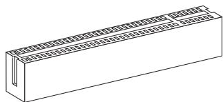
32-bit PCI cnot
BhIMaHHe
Ipeed yctahOBko nlln 13BneHennm Kapr pacuipenhy ybeintecb, yto kabel nItaHnO tKnUoyen O TneKtpnuecko cetn. IpoouTte DOKymentauNHO kaTp ypacuipenHn N BblONHnTe Heo6xOunMbte annapaTHBe nll nporpaMhIE yCTaHOBKN dnn daHHo nnatbI, takne kak nepembyKn, nepeknOyatee nn KOnfynypauNIO BIOS.
MapuTy3aun 3anpocnpepbvban PCI
IRQ - cokpaeeHne ot interrupt request (line) - linnna 3anpoca npepbBAHnna nnapaTHNA LINNA, no KOTOPoYUCTPOINCTBa MOryT NocblNaTcRHaN ppepbBAHnMnKpOpoecccopy. ObuHoe NoKJIoueHne PCI IRQ K KOHTaKTam UHHbPCI noka3aHo HnKe:
| Order1 | Order2 | Order3 | Order4 | |
| PCI Slot1 | INT E# | INT F# | INT G# | INT H# |
| PCI Slot2 | INT F# | INT G# | INT H# | INT E# |
| PCI Slot3 | INT G# | INT H# | INT E# | INT F# |
TexHonoria ATI CrossFireX™ (Multi-GPU)
ATI CrossFireXTM obecneuBaeT BO3MOxHocb T co3dAnn Hau6OJee MoUhIx multi-GPU nroPoBbix pnaTfopm. ATI CrossFireXTM no3BOJraT dBym nn 60oee rpaqueckmnpoecccopam pa6oTaT b MceTe dny UbeInuHEna 3D-npOu3BODntelbHoctn n npedOctabTReT BO3MOxHocTb NocTeNEHOrO MaC7aBupOBaHn rpaqueckoNpoDCStEmb, no3BOJra No6abTb DOnONHtE hBHe aanTepbAt TI RadeonTM HD noMepe Heo6xoDmocToN.CnCTemHa NpTaMoKet ATOmatueckn OnpeDenTb HauNueke konFurpaunn CrossFireXTM nporpaMMbIM CpeDCTBaMn, no3TOMy DOnONHtE hBbHex hAcTPOeB B IOS He Tpe6byTe. Cnedyte daHHbIM yKa3aHnM dny Co3DaHn CnCTeMbCrossFireXTM n3 DByx BnuDeokapt.
- YctaHOBInTe DBe BndeokapTb ATI RadeonTM HD B o6o cNoTa PCIE x16.
- YctaHOBnTe MoCTNK CrossFireXTM Ha KOHTaKTbIe pa3bEmbl BBepy BuDeOkaT (cMoTpInTe I3o6paXeHne HnKe). O6paTInTe BHNMaHne, YTO XOTy UCTaHOBJIeHbI DBe IIN 60Jee BuDeOkaPT, pa6OtaT TOIbKO BuDeOBxOdbI Ha BeDyUeK KapTe, N03TOMy MOHtOP CJIeDyET NOkJIIOuATb TOnbKO K HeI.
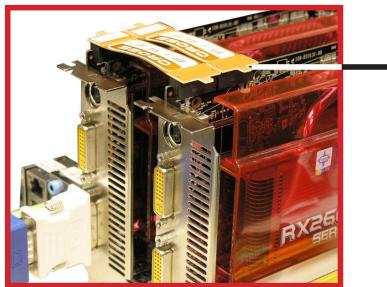
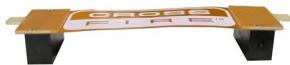
CoeHINTeNbHbIMoCTNK CrossFireXTM
BhimaHne
- FOtorpaФисnteMHоIПaTbI B 3tOM pa3deneпрИБeДнToJbKOДЯ Демонстраци. ВисnteMHоI ПaTbI MoKET BapbIpOBaTb B 3aBnCIMOCtN OT КулпенHoMоДeп.
- Ecnn Bbl cobupaetebc yctahOBuTb DBe BnDeoKapTb B pexnme CrossFireXTM, ybeuntecb TOM, YTO:
a. 3TN BnDcEOKapTb CdEJaHb OdHM PpOu3BOUnteJIem N IMMeIOT OOnHaKOBbIE cneucnkaun;
b. 3TN BnDEoKapTbI yCTaHOBnHeBb OBOnx CnHnx CnToax PCIE x16.
-
Y6eHntecb, yTO y BAC oBecneyeHO DoCTaTOHoe NITAHne uepe3 DonONHnTeIbHbI pa3bem nITaHnHa H BuDeOkaPte dIra ObecneyeHnE ee CTAbNbHo pa60tbl.
-Функця CrossFireXTM noДержИВаетс ТовkoВ WindowsXP Service Pack 2 (SP2)&WindowsXP Professional x64 Edition,WindowsVista&Windows7. -
Пос两款 установский Сбero anecdopaithoroi и рогамmaro obecne�еня, посязарузпесгему. Пос两款 BXODA B onepaioHHU CnCTeMу, клннite зачok "Catalyst™ Control Center" в сисмно облacrп панели задан. Ддя рабты CrossFireX™ вам hyжно BKIOHHTь орцю CrossFireX™, которя нахоится в Catalyst™ Control Center (сm. ИЗБраоженинке):
BhimhaHue
CnTeMaHa6a3eCrossFireXTM moKet pa6oTaB 4 peKImMax:
SuperTiling
- Scissor Mode
Alternate Frame Rendering
Super Anti-aliasing.
3a donoHnTeIbHoi nHopMauei o6paTntecb K pyKOBODCTBy noIb3ObaTeJIa OT npOn3BOUInTeJI BnDeOkaTpbl.
CBeTOBbIe INHdNkAToPbI
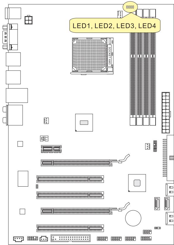
INHdkaTopbΦa3CPU:LED1,LED2,LED3,LED4
3TN INHdNkATOpbI NOKa3bIBaHT peKIM pa60bTI nCTOChNka nITaHnca CPU. INHΦopMaζnro COCTOHN INHdNkATOpB pINBeDeHa B tabnIe.
BkJIIOUey H BbIKIOUeyEH
| LED1 | LED2 | LED3 | LED4 | Mode |
| | | | | | | | | CPU Incpólbyet 1 φa3y piTaHЯ. |
| | | | | | | | | CPU Incpólbyet 4 φa3bI piTaHЯ. |
Hactpoika BIOS
B 3toi rnaBe npnboaTcO cHOBbIe CBeEHHa O pexmHe hactpoKn BIOS (BIOS SETUP), KOtOpbI nO3BOJAE TcAHOBHT ONTMaJIbHyIO KOHpIpyaUHO CnCTeMbI. 3TO T pexm MoKeT NOTpe6oBaTcBcRA B CneDyUOx CNyuaX:
Bo Bpem3aarp3kn cncTeMbI NOBbIeTcOo6ueHne 06 OuN6Ke C tpe6obAHnEM 3anyctntb BIOS SETUP.
Tpe6yeTc3aMeHntb 3aBOdCKne HaCTpoIKn Ha co6cTBHeHbIe.
BhimhaHue
1a86kBa COOTBETCTByeT u3roTOBnTeIIO BIOS (A = AMI, W = AWARD n P = PHOENIX).
Cneyuoune 4 ucbpbcooTBeCTbYIOHmOpy Moen.
CnéýuǒaāyúKBa obo3hauaet noctabuɪka yɪnceta (I = Intel, N = Nvidia, A = AMD, n V = VIA).
2 cneyuonhe 6kybbl o603naaioT 3aka3uKa MS = ctaHapTbn 3aka3uK.
V10.X COOTBETCTBYET HOMepy BepcunBIOS.
051010 -ДаТа Вынчka BIOS.
BxOДВpeXIMHacTpoKn
BkIIOHTe pntaHne KOMNbIOTepa. Pn3TOM 3aynctntc npoceDypa POST (TeCT BKNUChEHHa NtAHn).KOrda Ha 3KpaHe NOBNTC npuBeDeHHoe HnKe coo6ueHHe, HaxMITE KNaBnSy < DEL> dIy BxOa DpeKIM HacTroKn.
Press DEL to enter SETUP
(HaXmnte DEL nIy BxoJaB SETUP)
Ecni coo6eHHe nCye3I, a Bbl He ycneHn HaxaTb KnaBnUy, nepe3anyctnte CnCTeMy, BbKlNouB IN CHOBA BKnIOuB INTaHne, INn HaxaB KhoNky RESET. MoXHo, TaKke, nepe3anyctntb CnCTeMy, HaxaB OndHOBpeMeHHo KnaBnU
Pexim HactpoiK
BoiIaBpeXIMHacTpoiKn, BbIcpa3y yBvIaNTe ΓIaBHOe MeHIO.
Main Menu (Главhoe мени)
Главhoe MeHIO codepKNT cNICOK HAcTpoE, KOTOpBIE bbl MoKTe N3MeHnTb.ДЯ Bbl6opa moXHO nCNoJIb3OBAt bKnABuINu CO tpeKNaMn (↑↓). CnpabKa O bblpaHHOH NaCTpoJKe OTO6paJaTaC T B HIXKHe Yactn 3KpaHa.
Повменно
EcnBbObHApYKNTe,TO CnBea OT nyHKTa MeHIO NMeETc 3HaK npaBOr Oyka3aTeJRA 3To O3NaHaeT HAnuHne NOmEHIO, CoepXaUero DOnONHtEnbHbe HAcTPOKN KOTOpBle MOxHcCdeLaTb B 3Tom NyHKTe. NcNoIb3yIte ynpabJIouIe KlaBnSi (↑ ↓) dIra Bbl6opa, a 3aTeM haxMtTe
POnpo6Na cnpaBka
B pexime hactpoikn BIOS nmeetc B03MOXHOCTb nOlyeHnnoIpOboHn cnpaBKn. Ee moKHO BV3BaTbN 13 JIO6oR o MeHIO npocTbM HaxKaTneM
The Main Menu (Главhoe мени)
Pn Bxode B pexkim HacptpoKIN BIOS Ha 3kpahe OTo6paxaetcra TnaBHOe MeHIO. TnaBHOe MeHIO N03BOJRAET Bb6paTb FyHKmN HAcTPOKIN N IMeET Dba BapnAHTa BbIXoJa. IJI npereMeueHnI IO NyHKtAM NCNoJIb3yOTcR KNaBUn Co cTrpeKamN
| Standard CMOS Features | Cell Menu |
| Advanced BIOS Features | M-Flash |
| Integrated Peripherals | Overclocking Profile |
| Power Management Setup | Load Fail-Safe Defaults |
| H/W Monitor | Load Optimized Defaults |
| Green Power | Save & Exit Setup |
| BIOS Setting Password | Exit Without Saving |
Standard CMOS Features (CTaHapTbHe yHkun CMOS)
3TO MeHIO N03BOJnEYcTaHOBnTb OCHOBhIe npaMeTpbl KOHpNrgpaCmN CnCTEmbl (daTy, Bpemr n T.I.).
Advanced BIOS Features (Дононтеловье Функции BIOS)
3To MeHIO nCnOJb3yeTcAДЯ HAcTpoKIn CpeZmaJIbHbIX fYHKUBIOS.
Integrated Peripherals (BcTpoEHbIe nepupeprnHbIe yctpoIcTa)
3To MeHIO NcNoJIb3YeTcAДЯ HAcTpOuKn NapaMeTpOB BCTpoEHbIX nepupepInHbIX yctpoiCTB.
Power Management Setup (Hactpojka ynpablenia nitaHneM)
3To MEHIO NO3BOJAE T3aDaTb napamETpb ynpabNeHnI NITaHHe CNTeMbI.
H/W Monitor (MonHTop apnnapaTHou qactn)
3TOT nyHKT OTO6paxaET COCTOHNe annpaATHOJtNtIK.
Green Power
3To MeHIO nCIOB3yeTcI dIpeXIMOB 3HePrc6epeXeHn.
BIOS Setting Password (Пароль дocтуна Кнастоюкам BIOS)
3To MeHIO NcNoB3yETcA, YTO6bI 3aDaTb napObl.
Cell Menu (MeHIO y3Ja "Cell")
3TO MeHIO NO3BOJRAET ynpaBJIaTb TaKTOBbIMu YactOTAMN HnApjxKeHnMn npi pa3roHe CNTEmbl.
M-Flash
IcnoJIb3yeTcIaIyTeHnI/ npOuINBkN (UJIN 3anackn) BIOS c (B) BHeuHero hakOniTeJIa (ToJIbKO FAT/FAT32).
Overclocking Profile
IcnoIb3yeTcIyXpaHEnHa/3aRpy3knnapaMeTpOBB/m3CMOSBIOS.
Load Fail-Safe Defaults
3To MeHIO NcNoIb3yETcT dTn 3aRpy3Kn 3NaueHnBIOS, yCTaHOBJIeHHbIX npOn3BOIDTeMe nTn CTaBnBHO pa6Otbl CNTeMbI.
Load Optimized Defaults (YcTaHOBnTb ONTmAmNbHbHe NaCTpoKn)
3To MeHIO NcNoJIb3yeTcI dIy 3aRpy3KN HAcTpoEK N3rOToBnteIg IJRA ONTImaJIbHOI npOn3BOuNTeJIbHOCTn CnCTeMHoN IJIaTbI.
Save & Exit Setup (BbIXoD c coxpaHHeM hAcTpoE)
3aIncb nImMeHenn B CMOS n bIXoN n3 peKmHaCtpoKn.
Exit Without Saving (BbIXoI 6e3 coxpaHeneH)
OTmeHa BcEx N3MeHeHn N BbIXoN n3peXmHaCtpoKn.
B obsem cnyae, haxoJcB b pexime hactpoKBIOS, pekomehyetc BbINOHNITb cIeDyOUsne deiCTBn.
- Load Optimized Defaults: KnaBnIaMn ynpaBJIeHnra ( ) BbIbepnte npHKT Load Optimized Defaults n haxmTe
, noRbTc sCneDyUoee coo6uHeHne:
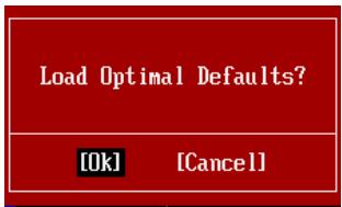
HaxmTe [Ok], 3r6bI 3arpy3nTb HacrpoKn IOn yMOJuaHIO IIn ONTMaJIbHOI npON3BOIDTeNbHOCTN CnCTeMbI.
- Setup Date/ Time: Bыберпe Standard CMOS Features и НжмeTe
Ддь Вхда в мени. Установite дату и Врем в COOTВETCTBYоциХ полax.
Haxmnte [Ok], yTo6bI coXpaHnTb KoHpyrpaZuIO n BbItn n3 BIOS Setup.
BhimaHae
PnBBeHnHa BbIe KOhunrgpaun noXoNT nIg oBSeO npImHeHn. EcnJge Bam Tpebyotc 6oJe ToKne HacTpoiBIOS, oBaPATeCb K anrnnckon BepnnpykoBDCTBa Ha Be-CAITE MSl.
- Pa3dien Cell Menu: 3To MeHIO npEHa3NaYeHO nIy ONbITbIX nOlb3OBaTeJIe I npEoCTabJrE TOB3MOXHOCTn dIy pa3roHa CnCTeMbI.

BHTMAHNE
He MeHryTe 3Tu HAcTPOiKN,ecnBbI He 3HaKOMbl C OcObeHHocTAmu TOHKoHacTPOiKN YUnCeTOB.
Current CPU/DRAM/CPU-NB Frequency
3Tn nyHkTBI nokaBbAIO T EkyuO yactOTy CPU u ckopocTb namrtn n CPU-NB. ToIbko dnyuTeHn.
CPU Specifications
Haxmnte
CPU Technology Support
Haxmnte
CPU Feature
Haxmnte
AMD Cool'n'Quiet
TexhONorIa Cool'n'Quiet no3BOnJeT 3ΦΦeKTHBHO dInHAMnueckn n3MeHrTa qAcToTy CPU n3hepronotpe6bHeHne cNCTembl.
BhimaHine
Ytoby6eDntbC8B TOM, YTO TexHOnrna Cool'n'Quiet BKnHoueHa npabotaertnpabnIbHo, Heo6xOdmo:
- 3aɪtn B npɒrρaʊmMy BIOS Setup, n Bbɪbpaɪt b Cell Menu. Hauɪdɪte AMD Cool'n'Quiet noD Cell Menu, n yctaɪhɒbɪte er o B "Enabled".
- B Windows BBbepuTe [Start]->[Settings]->[Control Panel]->[Power Options]. BoiDte B Power Options Properties, BBbepuTe Minimal Power Management B Power schemes.
C1E Support
BkIouHTe 3OT nyHKT IJn CHNKeHnE 3HeprOnoTpe6JIeHnCpu, KOrda OH he pa60taet. He BCE npOceccopbI noDdepKnBaIoT Enhanced Halt state (C1E).
SVM Support
3TOT nyHKT nCOnb3yETcI dNBAKIOUeHn/ BblKIOUeHn SVM.
AMD Cool'n'Quiet
TexhONorN Cool'n'Quiet no3BOnJrE 3ΦΦeKTHBHO DnHaMnueckn n3MeHrTb YactOTy CPU n3hepronotpe6IeHne CnCTembl.
C1E Support
BkIuHTe 3OT nyHKT dIa cHnKeHna 3HeprOnoTpe6NeHna CPU, KOrda OH He pa6Otaet. He BCE npouecocbpI noDaePKBaIOT Enhanced Halt state (C1E).
Adjust CPU FSB Frequency (MΓu)
3TOT nyHKT no3BONJET Bb6paTb yactOty FSB npoceccopa (B MfU).
OC Stepping
3TOT nyHKT noRbIeTcno nOte yCTaHOBKn YacToTB pa3roHa B "Adjust CPU FSB Frequency (Mf). N noRbIeTc cneDyUoNn NyKt. OH no3BOJIeT oCyIeCTbIaRHO shar 3a sharom noCte 3arpy3Kn cnCTeMbI.
Start OC Stepping From (M u)
3TOT nyHKT n03BOJIeYCTaHOBnTB hauaJIbHoe 3HaueHHe TAKTOB O YACTOTb (FSB clock). Cntema 3arpy3ntcC hauaJIbHbIM 3HaueHneM TAKTOB O YACTOTb (FSB clock), a NOTOM HauHET pa3roHrTB CNTeMy C hauaJIbHOrO 3HaueHnI Wa r 3a warom yctaHOBJIeHHbIM B "Adjust CPU FSB Frequency (M u)
OC Step
3TOT nyHKT nCnoNb3yETc dIa 3aDaHnIwa pa3roHa TaKToB O YaCTOBy FSB.
OC Step Count Timer
3TOT nyHKT nCnoIb3yeTc dIy yCTaHOBKn BpeMeHN 3aJeppKk KaJdoRo Waara.
Adjust CPU Ratio
3TOT nyHKT nCnOJIb3yETcI dIpeRyIINPOBkMHOKInTeI npOeCCopa. OH DocTyneH ToIbKO TOrDa, KOrDa npOeCCOP noDdepXINBaET 3Tu yHKUHO.
Adjusted CPU Frequency (MΓι)
3TOT nyHKT nokaibaaTekyuio yactOty CPU. TOnbKO dnyteHnA.
Adjust CPU-NB Ratio
3TOT nyHKT nCnoJb3yETc dIg perynipOBKn cactOtbl CPU-NB.
Adjusted CPU-NB Frequency (MΓu)
3TOT nyHKT noka3bIbae TekyU Yo cactOy CPU NB. TOnbKO dnyTeHnA.
Unlock CPU Core
3TOT nyHKT nCnOJIb3yETcI dI pya36bNOKIPOBKn CPU core. CLeNyIe Yka3aHnIe M HnKe dI pya36bNOKIPOBKn CPU core unlocked b hAcToPoiKe BIOS.
BHIMAHWE
-Данhoe DeiECTBnE pa3bIOKIpOBKn CPU core 3aBucnt OT cnocoboctn/ xapaKTepeuCtIKOB CPU n He rapaHTnpyetc.
B 3aBncMocTn OT xapaKTepeNtKOB CPU, KOrda nOraBJIeTc HecTa6bIbHa cnTuayuIyIa, NOxAlyuICTa, BOCCTaHOBInTe HAcTpoIK CNCTeMbI NO yMOJUHaHIO.
- Bam можно тоadingу сюговпь количесво унсетов в стогше Быстroduйства дисерета заши Windows.
Advanced Clock Calibration
3TOT nyHKT nCnOJIb3yeTcI dIpa 3raHOa. YcTaHOBka B [Enabled] no3BONJeYCTaHOBNT bactoty CPU bIiHe. OH doctynen ToIbKO torda, KOrDa npoceccop noDdepxnBaET 3Ty fynKciHo.
CPU Core Control
ТOTNYнКИСПОЛБ3уETСДЯ КОТРОПОВАHAHomeа РоцeccOPHOrO YUnceTa.
Пи усановke B [Auto], CPU pa6oTaEТ NOД HomepOM YUncetOB no yMOnuHaHIO.
Пи усановke B [Manual], Bam MoKHO BKJIQUaTb/BbIKJIQUaTb onpeDeJIeHbI YUncetCPU.
Core 1/2/3/4
Tn NyKtbI NcNoJIb3yOTc IaI BkHoueHra/BbIKHoueHra YInCeTOB 1/2/3/4.
OC Genie Lite
YctaHOBka 3TORO nyHKta B [Enabled] no3BOLJrE CnCTeMe ONpeJeTb MaKcIMaJIbHyIO yactOtTy FSB n pa3roH aBTOMaTIueckn. EcII pa3roH He ydaIcra, Bam MOxHO yMeHbIHTb TaKTobyIO yactOtTy FSB dIra pa3roHa ydaIHO.
MEMORY-Z
HaxmTe
DIMM1~4 Memory SPD Information
HaxmTe
Advance DRAM Configuration
HaxmTe
DRAM Timing Mode
3TOT nyHKT no3BONJET ABTomATUHeCKN ONpeJeIaTB BCE BpeMeHHbIe napametpbI DRAM.
DRAM Drive Strength
3Ta onuIy N03BONJET KOHTPOINPOBaTb FOpMy CnHHaJa 1aHHbIX NaMRTN. YBeInuHeHne KpyTN3HbI FOPOHTA CnHAna MOKET NOBbICNTb CTaBnJIbHOCTb CnCTEmbl npn pa3roHe.
DRAM Advance Control
3TOT NYHKI IMeET BO3MOXHOCTb ABTomATnueCKN ONpeJeIaTb DOIOJIHITeJIbHbIe BpeMeHHIbe npaMeTpbl DRAM.
1T/2TMemory Timing
3TOT nyHKT ONpeJeIeET CKOpocTb BbIaUH KOMaHSDRAM. BbI6op [1T] nepeBOuNT CnHaJIbHbIK KOHTpOJIep SDRAM B pexIM pa60tBu 1T (T=clock cycles). BbI6op [2T] nepeBOuNT CnHaJIbHbIK KOHTpOJIep SDRAM B pexIM pa60tBu 2T.
DCT Unganged Mode
3TOT nyHKT nCnoJIb3yETcI IJRA 6bEduHEnra DByx 64-6uTHbIX DCT B OdINH 128-6uTHbI INTEpeic.
Bank Interleaving
Bank Inter leaving yBnIeTcB BaxKbIM npaMeTpom, BInyHouzim Ha npOn3BoUnteHbOcTb naMByT. Ero BKIoUChHe NIO3BOJraTe oBaIaTbcr K HeCKoJIbKm 6aHkam nAmTn OndHOBpeMeHHO.
Power Down Enable
3TOT nyHKT KOHTPOINPYET pa60Ty TEXHONORIN 3HEPROCBepeKeHn. PpN OTCYCTBNNOBpaUeHn K pAMrTN B TeueHne HeKOTOPORO BpeMeHn, CNTema ABTOMATNueCKNuMehbShaet NITaHne dIy pAmrTN.
MemCik Tristate C3/ATLVID
3TOT nyHKT NO3BOJAREB KJIIOUaTB/BbIKIOUaTBpeKIM pa6Otbl C TpeMc COCTOHNMA BO BpemC3 n ATLVID.
FSB/DRAM Ratio
3TOT nyHKT NOBONAEr perynipoBaTa yacToTy FSB n DRAM.
Adjusted DRAM Frequency (MΓu)
3TOT nyHKT noka3bIbaeT kcyuio yactOtu namrtn. TOnbKO dnyTeHnA.
HT Link Control
HaxmTe
HT Incoming/Outgoing Link Width
3TOT nyHKT onpeJeIeT uipnHy BXoJaIe/NcXOJaIe IINH NTpn yCTaHOBKe B [Auto], cNCTema aBTOMaTInueckn onpeJeIeT uipnHy IINHbHT.
HT Link Speed
3TOT nyHKT NO3BOJAEY cTaHOBnTB cKOpocb nepeaun no sInHe HyperTransport. Ipn yctaHOBKe B [Auto], cnCTema aBtOMaTuYeCKn onpeJeAeRcKOpocb sInHbI HT.
Adjusted HT Link Frequency (MΓμ)
3TOT nyHKT noka3bIbae TAKTOBYU qACTOty uINhbl HT. ToIbKO dIy cTeHnIa.
Adjust PCI-E Frequency (MΓι)
3TOT nyHKT n03BONaET yCTaHOBnTB YaCTOty PCIE (BMfU).
Auto Disable DRAM/PCI Frequency
Пиу усановke 3нанья [Enabled], систema OTKIIOHIT HeINCNoJIb3yEmble pa3bEmblamЯтNiPCI,чTo npBédET K ChnIXeHInO yOBHЯЗЕКТРOMaHRHTbIx NOMex (EMI).
CPU Voltage (V)/CPU-NB Voltage (V)/DRAM Voltage (V)/NB Voltage (V)/SB Voltage (V)/HT Link Voltage (V)
Tn nyktbI no3BOLaIOT peryInpoBaTb HanpJxHHe CPU, namrtn, n Ynnceta.
Spread Spectrum
Tak KaTobBm rHePApOp CnCTeMHoN pIaTbIMyNbchbI, To erO pa60Ta Bb3bBaET 3JIeKTPomarHnTHbIe nomexi - EMI (Electromagnetic Interference).ФункцЯ Spread Spectrum cnHkaet 3tN nomexi, reHepupy crJaXeHHbIe IMnylbcbl.
BhimhaHne
- Ecnn y Bac Het npoblem c nomexamn, octabte 3naeHne [Disabled] (zanpeueho) Дялушew CTa6bIbHOCTn n pOn3BOuNTeBHOCTn. Ondako, ecnn y Bac BO3NkaHOT 3NeKTPomarHHTbIe nomexn, Bbl6epnte Spread Spectrum dans nx yMeHbSeHnra.
-ЧмбльшеЗачениSpreadSpectrum,temнижебудетуровьзлкгомагHTbIXnomex,HOcntema ctaHET Mehee ctabnblho.ДявьбopaпoxdяцeroЗачениSpreadSpectrum,Cbepbtecbco3haeynmmyuypobne3лкгомагHTbIXnomex,yctahOBNeHHbix3akOHoataTeBCTBOM. - He 3a6ydbTe 3anpeTntb nCnObnzOBaHne yHKnUu Spred Spectrum, ecnn Bbl "pa3roHaeTe" CnCTeMHny PnATy. 3To Heo6xOJMo, TaK KaJ daxe He6oBbOu Jpe6e3r CnHAnOB TaKTOBOrO rHePaTopa MoKe TpNBecTn K OTKa3y "pa3orHaHHoro" npouceccopa.
CBeHnO nporpaMMHom oecneueHH
YctahOBtBe B DVD npBOD nck Driver/Utility (DpaBebpbI u yTnInTbI) n3 KOMPNeKta IOCTaBKn CnCTeMHOn PnAToB. ABTomAtuYeCKn 3aNyCTntCra IHCTaJIaIaIyN. HaxMITE Ha HA3BaHne dpaBepa/ yTnInTbI u cIeMyTe INcHTpyKzmaM ha 3kpaHe IJr 3aBepSeHnI HCTaJIaIaIyN. Dnck Driver/Utility codepKNT:
- Driver menu (Ménhó dpánbépoB) - PpéndctabnIeT npeyehb dOCTynbIX dpánbépoB. YctahOBiTE dpánbépoI DnA NOkJIIOUeHnHEo6xOIMbIX yCTPOIcTB.
- Utility menu (Meho ytnnt) - Poka3bBAeT ytnntbl, KOTOpIe noDepKnaTOc cnCTemHoi nlaToi.
BhimaHue
Ioxaynuicta, noceitte Be6caT MSI nna onnyeHn cambix HObIX dpaiBepOB IN BIOS, KOtOpblie no3BOJAT ynuuHT bpOn3BOUnteHbOCTb CNTeMbI.