B75MA-G43 - Motherboard MSI - Free user manual and instructions
Find the device manual for free B75MA-G43 MSI in PDF.

User questions about B75MA-G43 MSI
0 question about this device. Answer the ones you know or ask your own.
Ask a new question about this device
Download the instructions for your Motherboard in PDF format for free! Find your manual B75MA-G43 - MSI and take your electronic device back in hand. On this page are published all the documents necessary for the use of your device. B75MA-G43 by MSI.
USER MANUAL B75MA-G43 MSI
natural_image
Abstract illustration of a globe with orbiting lines and a stylized human figure, no text or symbols present.msi™
B75MA-G43 series
MS-7798 (v2.x) Mainboard
Copyright Notice
The material in this document is the intellectual property of MICRO-STAR INTERNATIONAL. We take every care in the preparation of this document, but no guarantee is given as to the correctness of its contents. Our products are under continual improvement and we reserve the right to make changes without notice.
Trademarks
All trademarks in this manual are properties of their respective owners.
■ MSI® is registered trademark of Micro-Star Int'l Co., Ltd.
■ NVIDIA® is registered trademark of NVIDIA Corporation.
■ ATI ^® is registered trademark of AMD Corporation.
■ AMD® is registered trademarks of AMD Corporation.
Intel® is registered trademarks of Intel Corporation.
■ Windows® is registered trademarks of Microsoft Corporation.
■ AMI® is registered trademark of American Megatrends Inc.
■ Award® is a registered trademark of Phoenix Technologies Ltd.
■ Sound Blaster® is registered trademark of Creative Technology Ltd.
■ Realtek® is registered trademark of Realtek Semiconductor Corporation.
■ JMicron® is registered trademark of JMicron Technology Corporation.
■ Netware® is a registered trademark of Novell, Inc.
Lucid® is trademarks of LucidLogix Technologies, Ltd.
■ VIA® is registered trademark of VIA Technologies, Inc.
■ ASMedia® is registered trademark of ASMedia Technology Inc.
■ iPad, iPhone, and iPod are trademarks of Apple Inc.
Revision History
| Revision | Revision History Date | Date |
| V2.0 First release for PCB 2.X 2012/ 04 | ||
Technical Support
If a problem arises with your system and no solution can be obtained from the user's manual, please contact your place of purchase or local distributor. Alternatively, please try the following help resources for further guidance.

Visit the MSI website for technical guide, BIOS updates, driver updates, and other information:
http://www.msi.com/service/download

Contact our technical staff at:
http://support.msi.com
Safety Instructions
■ Always read the safety instructions carefully.
- Keep this User’s Manual for future reference.
- Keep this equipment away from humidity.
■ Lay this equipment on a reliable flat surface before setting it up.
■ The openings on the enclosure are for air convection hence protects the equipment from overheating. DO NOT COVER THE OPENINGS.
■ Make sure the voltage of the power source is at 110/220V before connecting the equipment to the power inlet.
■ Place the power cord such a way that people can not step on it. Do not place anything over the power cord.
■ Always Unplug the Power Cord before inserting any add-on card or module.
■ All cautions and warnings on the equipment should be noted.
■ Never pour any liquid into the opening that can cause damage or cause electrical shock.
■ If any of the following situations arises, get the equipment checked by service personnel:
○ The power cord or plug is damaged.
○ Liquid has penetrated into the equipment.
- The equipment has been exposed to moisture.
The equipment does not work well or you can not get it work according to User's Manual.
- The equipment has been dropped and damaged.
○ The equipment has obvious sign of breakage.
■ DO NOT LEAVE THIS EQUIPMENT IN AN ENVIRONMENT ABOVE 60°C (140°F), IT MAY DAMAGE THE EQUIPMENT.
FCC-B Radio Frequency Interference Statement
This equipment has been tested and found to comply with the limits for a Class
B digital device, pursuant to Part 15 of the FCC Rules. These limits are designed to provide reasonable protection against

N1996
harmful interference in a residential installation. This equipment generates, uses and can radiate radio frequency energy and, if not installed and used in accordance with the instructions, may cause harmful interference to radio communications. However, there is no guarantee that interference will not occur in a particular installation. If this equipment does cause harmful interference to radio or television reception, which can be determined by turning the equipment off and on, the user is encouraged to try to correct the interference by one or more of the measures listed below.
○ Reorient or relocate the receiving antenna.
○ Increase the separation between the equipment and receiver.
○ Connect the equipment into an outlet on a circuit different from that to which the receiver is connected.
Consult the dealer or an experienced radio/television technician for help.
Notice 1
The changes or modifications not expressly approved by the party responsible for compliance could void the user's authority to operate the equipment.
Notice 2
Shielded interface cables and A.C. power cord, if any, must be used in order to comply with the emission limits.
VOIR LA NOTICE D'INSTALLATION AVANT DE RACCORDER AU RESEAU.

text_image
Micro-Star International MS-7798This device complies with Part 15 of the FCC Rules. Operation is subject to the following two conditions:
1) this device may not cause harmful interference, and
2) this device must accept any interference received, including interference that may cause undesired operation.
Battery Information

European Union:
Batteries, battery packs, and accumulators should not be disposed of as unsorted household waste. Please use the public collection system to return, recycle, or treat them in compliance with the local regulations.

Taiwan:
For better environmental protection, waste batteries should be collected separately for recycling or special disposal.
廢電池請回收
California, USA:
The button cell battery may contain perchlorate material and requires special handling when recycled or disposed of in California.
For further information please visit:
http://www.dtsc.ca.gov/hazardouswaste/perchlorate/
CAUTION: There is a risk of explosion, if battery is incorrectly replaced.
Replace only with the same or equivalent type recommended by the manufacturer.
Chemical Substances Information
In compliance with chemical substances regulations, such as the EU REACH Regulation (Regulation EC No. 1907/2006 of the European Parliament and the Council), MSI provides the information of chemical substances in products at:
http://www.msi.com/html/popup/csr/evmtprtt_pcm.html
BSMI EMI 聲明
警告使用者:
WEEE (Waste Electrical and Electronic Equipment) Statement
ENGLISH
To protect the global environment and as an environmentalist, MSI must remind you that...

Under the European Union ("EU") Directive on Waste Electrical and Electronic Equipment, Directive 2002/96/EC, which takes effect on August 2005, products of "electrical and electronic equipment" cannot be discarded as municipal wastes anymore, and manufacturers of covered electronic equipment will be obligated to take back such products at the end of their useful life. MSI will comply with the product take back requirements at the end of life of MSI-branded products that are sold into the EU. You can return these products to local collection points.
DEUTSCH
Copyright Notice ....iii
Trademarks ...... ii
Revision History...... ii
Technical Support......iii
Safety Instructions
FCC-B Radio Frequency Interference Statement...... iv
Battery Information v
Chemical Substances Information W
BSMI EMI 聲明 v
WEEE (Waste Electrical and Electronic Equipment) Statement ...... vi
Chapter 1 Getting Started....1-1
Packing Contents 1-2
Optional Accessories 1-2
Assembly Precautions 1-3
Mainboard Specifications 1-4
Connectors Quick Guide 1-6
Back Panel Quick Guide 1-8
CPU (Central Processing Unit) 1-10
Mounting Screw Holes 1-14
Power Supply 1-15
Memory 1-16
Expansion Slots 1-18
Video/ Graphics Cards 1-19
Internal Connectors 1-22
Jumper 1-29
Chapter 2 BIOS Setup 2-1
Entering....2-2
Overview 2-2
Boot device priority bar 2-3
Operation 2-4
SETTINGS 2-5
OC....2-11
ECO 2-17
BROWSER 2-18
Installing Winki 2-18
Updating the BIOS with Live Update 2-19
UTILITIES 2-20
SECURITY 2-22
Appendix A Realtek Audio ...... A-1
Installing the Realtek HD Audio Driver ....A-2
Software Configuration ......A-3
Hardware Default Setting ......A-5
Appendix B Intel SBA ...... B-1
Prerequisites....B-2
Installing Intel SBA ......B-3
Software Configuration ......B-3
Help Button ......B-4
Appendix C Install Windows XP Notes ...... G-1
Installing Windows XP with IDE Mode C-2
Installing Windows XP with AHCI Mode C-3

natural_image
Abstract illustration of a globe with orbiting lines and abstract shapes, no text or symbols present.Chapter 1
Getting Started
Thank you for choosing the B75MA-G43 Series (MS-7798 v2.X) Micro-ATX mainboard. The Series mainboards are based on Intel® B75 chipset for optimal system efficiency. Designed to fit the advanced Intel® LGA1155 processor, the B75MA-G43 Series mainboards deliver a high performance and professional desktop platform solution.
Packing Contents
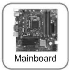
natural_image
Close-up of a computer motherboard with visible slots and ports (no text or symbols on the circuit itself)
text_image
Driver / Utility DVD
text_image
User Guide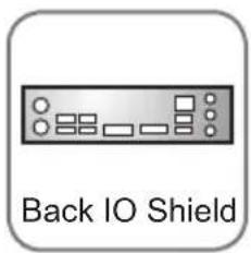
text_image
Back IO Shield
natural_image
SATA Cable cable with a black connector, labeled below (no additional text or symbols visible)Optional Accessories
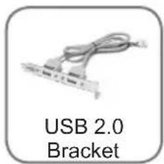
text_image
USB 2.0 Bracket
text_image
USB 3.0 Bracket
text_image
eSATA Power Cable
text_image
eSATA Bracket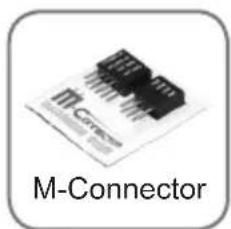
text_image
M-Connector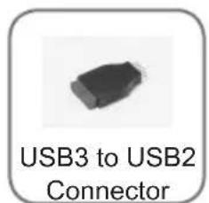
text_image
USB3 to USB2 Connector
text_image
SATA Power Cable* These pictures are for reference only and may vary without notice.
* The packing contents may vary according to the model you purchased.
* If you need to purchase the optional accessories or request part numbers, please visit the MSI website at http://www.msi.com/index.php or consult the dealer.
Assembly Precautions
■ The components included in this package are prone to damage from electrostatic discharge (ESD). Please adhere to the following instructions to ensure successful computer assembly.
■ Always turn off the power supply and unplug the power cord from the power outlet before installing or removing any computer component.
■ Ensure that all components are securely connected. Loose connections may cause the computer to not recognize a component or fail to start.
■ Hold the mainboard by the edges to avoid touching sensitive components.
■ It is recommended to wear an electrostatic discharge (ESD) wrist strap when handling the mainboard to prevent electrostatic damage. If an ESD wrist strap is not available, discharge yourself of static electricity by touching another metal object before handling the mainboard.
■ Store the mainboard in an electrostatic shielding container or on an antistatic pad whenever the mainboard is not installed.
■ Before turning on the computer, ensure that there are no loose screws or metal components on the mainboard or anywhere within the computer case.
■ Do not use the computer in a high-temperature environment.
■ Do not boot the computer before installation is completed. This could cause permanent damage to the components as well as injury to the user.
■ If you need help during any installation step, please consult a certified computer technician.

Important
A screwdriver (not included) may be required for computer assembly.
Mainboard Specifications
Processor Support
■ Support 3 ^rd Generation Intel ^® Core ^TM i7/ Core ^TM i5/ Core ^TM i3/ Pentium ^® / Celeron ^® Processors for LGA 1155 socket
Chipset
Intel®B75 chipset - Supports Intel SBA
Memory Support
- 4x DDR3 DIMMs support DDR3 1066/ 1333/ 1600* (22nm CPU required) DRAM (32GB Max.) - Supports Dual-Channel mode, two DIMMs per channel
LAN
■ Supports LAN 10/100/1000 Fast Ethernet by Realtek® RTL8111E
Audio
■ Integrated HD audio codec by Realtek® ALC887
■ 8-channel audio with jack sensing
■ Compliant with Azalia 1.0 Spec
SATA
■ 1x SATA 6Gb/s port (SATA1) by Intel® B75
■ 5x SATA 3Gb/s ports (SATA2\~6) by Intel®B75
USB 3.0
■ 2x USB 3.0 rear IO ports by Intel® B75
■ 1x USB 3.0 onboard connector by Intel® B75
Multi-GPU
■ Supports ATI® CrossFire™ Technology
Connectors
■ Back panel
- 1x PS/2 keyboard/ mouse port
- 4x USB 2.0 ports
- 2x USB 3.0 ports
- 1x LAN port
- 1x HDMI® port**, supporting a maximum resolution of 1920x1200
- 1x VGA port**, supporting a maximum resolution of 2048x1536
- 1x DVI-D port**, supporting a maximum resolution of 1920x1200
- 6x audio ports
- ** This platform supports dual-display function by any two output ports (HDMI+DVI, DVI+VGA or VGA+HDMI).
■ On-Board
- 1x Front Panel Audio connector
- 1x Parallel Port connector
- 2x USB 2.0 connectors
- 1x USB 3.0 connector
-
1x Chassis Intrusion connector
-
1x Serial Port connector
- 1x TPM Module connector
Slots
■ 2x PCIe 3.0 x16 slot
- PCI_E1 supports up to PCIe 3.0 x16 speed
- PCI_E2 supports up to PCIe 3.0 x4 speed
■ 2x PCI slot
Form Factor
■ Micro-ATX (24.4 cm X 24.4 cm)
Mounting Screw Holes
■ 8x mounting holes

For the latest information about CPU, please visit http://www.msi.com/service/cpu-support

For more information on compatible components, please visit http://www.msi.com/service/test-report
Connectors Quick Guide
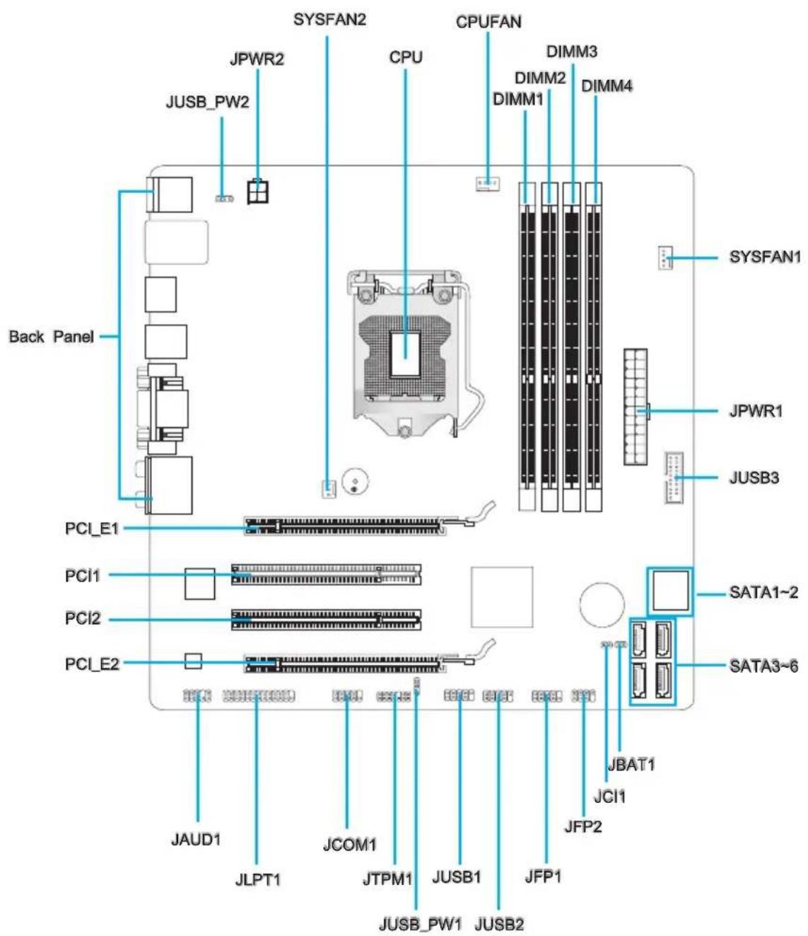
text_image
Back Panel JUSB_PW2 JPWR2 SYSFAN2 CPU CPUFAN DIMM3 DIMM1 DIMM2 DIMM4 JUSB3 JSPFAN1 JPYWR1 PCI_E1 PCI1 PCI2 PCI_E2 JAUD1 JLPT1 JCOM1 JTPM1 JUSB1 JFP1 JUSB_PW1 JUSB2 JBAT1 JCI1 SATA1~2 SATA3~6 JFP2Connectors Reference Guide
| Port Name | Port Type | Page | Port Type | Page |
| Back Panel | 1-8 | |||
| CPU | LGA 1155 | CPU Socket | 1-10 | |
| CPUFAN,SYSFAN1~2 Fan Power Connectors | 3 | |||
| JAUD1 Front Panel Audio Connector | 7 | |||
| JBAT1 Clear CMOS Jumper | 0 | |||
| JCI1 Chassis Intrusion Connector | 6 | |||
| JCOM1 Serial Port Connector | 8 | |||
| JFP1, JFP2 Front Panel Connectors | 4 | |||
| JLPT1 Parallel Port Connector | 1-28 | |||
| JPWR1 ATX 24-pin Power Connector | 5 | |||
| JPWR2 ATX 4-pin Power Connector | 5 | |||
| JTPM1 TPM Module Connector | 7 | |||
| JUSB_PW1~2 USB power Jumper | 9 | |||
| JUSB1~2 | USB 2.0 Expansion Connectors | 1-26 | ||
| JUSB3 | USB 3.0 Expansion Connector | 1-25 | ||
| PCI1, 2 | PCI Expansion Slot | 8 | ||
| PCI_E1, 2 | PCIe x16 Expansion Slot | 1-18 | ||
| SATA1 SATA 6Gb/s Connector | 2 | |||
| SATA2~6 | SATA 3Gb/s Connector | 1-22 | ||
Back Panel Quick Guide
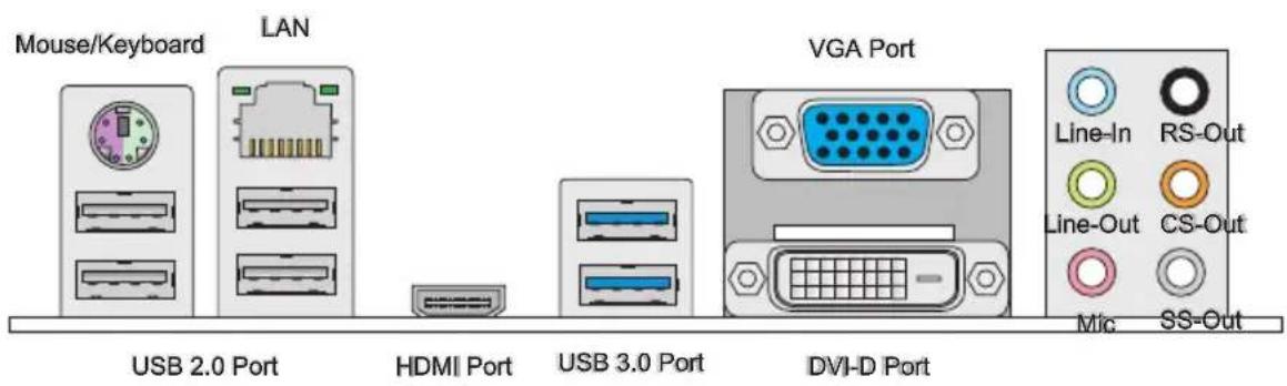
text_image
Mouse/Keyboard LAN USB 2.0 Port HDMI Port USB 3.0 Port DVI-D Port VGA Port Line-In RS-Out Line-Out CS-Out Mic SS-Out▶ Mouse/Keyboard
A combination PS/2 ^® mouse/keyboard DIN connector for a PS/2 ^® mouse/keyboard.
▶ USB 2.0 Port
The USB 2.0 port is for attaching USB 2.0 devices such as keyboard, mouse, or other USB 2.0-compatible devices.
▶ USB 3.0 Port
USB 3.0 port is backward-compatible with USB 2.0 devices. It supports data transfer rate up to 5 Gbit/s (SuperSpeed).

Important
In order to use USB 3.0 devices, you must connect to a USB 3.0 port. If a USB cable is used, it must be USB 3.0 compliant.
▶ HDMI Port

The High-Definition Multimedia Interface (HDMI) is an all-digital audio-video interface that is capable of transmitting uncompressed streams. HDMI supports all types of TV formats, including standard, enhanced, or high-definition video, plus multi-channel digital audio on a single cable.
▶ DVI-D Port
The DVI-D (Digital Visual Interface- Digital) connector can be connected to a LCD monitor, or a CRT monitor with an adapter. To connect a monitor, please refer to the monitor's manual for more information.
▶ VGA Port
The DB15-pin female connector is provided for monitor.

Important
This platform supports dual-display function by any two output ports (HDMI+DVI, DVI+VGA or VGA+HDMI).
| HDMI+DVI DVI+VGA VGA+HDMI | |||
| Extend mode(Extend the desktop to the second monitor) | ○○○ | ||
| Clone mode(Two monitors have the same screen) | ○○○ | ||
▶ LAN
The standard RJ-45 LAN jack is for connecting to a Local Area Network (LAN).

| LED Color LED State Condition | Condition | ||
| Left Yellow Off LAN link is not established. | |||
| On(Steady) LAN link is established. | |||
| On(flashing) The computer is communicating with another computer on the network. | |||
| Right | Green Off 10 Mbits/sec data rate | ||
| Orange On 1000 Mbits/sec data rate | |||
▶ Audio Ports
These connectors are used for audio devices. The color of the jack refers to the function of the connector.
■ Blue-Line in: Used for connecting external audio outputting devices.
■ Green- Line out: Used as a connector for speakers or headphone.
■ Pink- Mic: Used as a connector for a microphone.
■ Black- RS-Out: Rear surround sound line out in 4/5.1/7.1 channel mode.
- Orange-CS-Out: Center/ subwoofer line out in 5.1/7.1 channel mode.
Gray- SS-Out: Side surround sound line out in 7.1 channel mode.
CPU (Central Processing Unit)
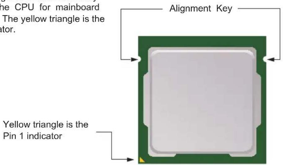
Introduction to the LGA 1155 CPU
The surface of the LGA 1155 CPU has two alignment keys and a yellow triangle to assist in correctly lining up the CPU for mainboard placement. The yellow triangle is the Pin 1 indicator.
text_image
The CPU for mainboard The yellow triangle is the ator. Alignment Key Yellow triangle is the Pin 1 indicatorImportant
Overheating
Overheating can seriously damage the CPU and mainboard. Always make sure the cooling fans work properly to protect the CPU from overheating. Be sure to apply an even layer of thermal paste (or thermal tape) between the CPU and the heatsink to enhance heat dissipation.
Replacing the CPU
When replacing the CPU, always turn off the system's power supply and unplug the power supply's power cord to ensure the safety of the CPU.
Overclocking
This mainboard is designed to support overclocking. Before attempting to overclock, please make sure that all other system components can tolerate overclocking. Any attempt to operate beyond product specifications is not recommend. MSI does not guarantee the damages or risks caused by inadequate operation beyond product specifications.
CPU & Cooler Installation
When installing a CPU, always remember to install a CPU cooler. A CPU cooler is necessary to prevent overheating and maintain system stability. Follow the steps below to ensure correct CPU and CPU cooler installation. Wrong installation can damage both the CPU and the mainboard.
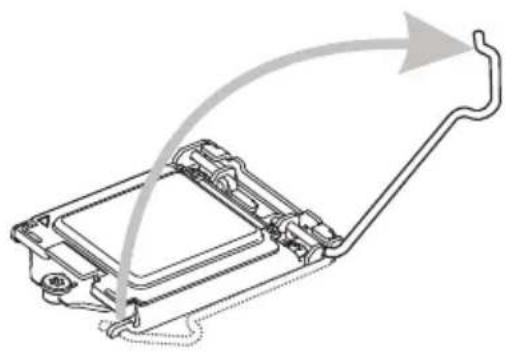
-
Thunhoading plate the endoading lever to the fully open position.
-
automatically lift up as the loading lever is pushed to the fully open position. Do not touch any of the CPU socket pins.
natural_image
Technical line drawing of a mechanical assembly with curved arrows indicating motion or force (no text or symbols)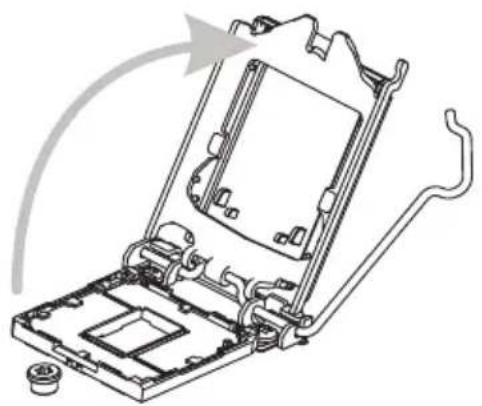
natural_image
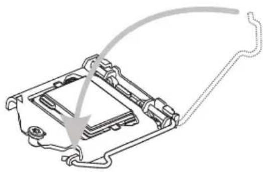
Technical line drawing of a mechanical assembly with no visible text or symbols-
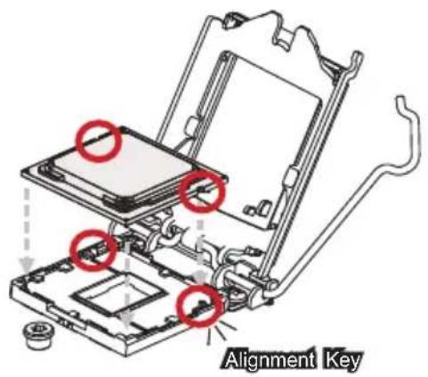
Close the loading CPU plate and then CPU socket. Be sure to hold the CPU by the base with the metal contacts facing downward. The alignment keys on the CPU will line up with the edges of the CPU socket to ensure a correct fit.
-
the plastic protective cap.
text_image
Alignment Key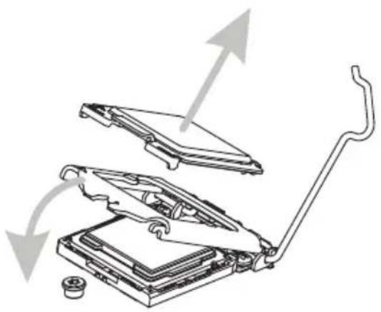
natural_image
Diagram of a mechanical device with exploded view showing internal components and directional arrows (no text or symbols)-
EvespectheadCPuthio lakeckoff it is properly seated in the socket. Press the loading lever down and lock it under the retention tab.
-
thermal paste (or thermal tape) on the top of the CPU. This will help in heat dissipation and prevent CPU overheating.
natural_image
Technical line drawing of a mechanical component with a curved wire and arrow indicating direction (no text or symbols)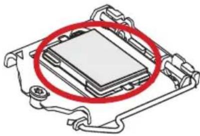
natural_image
Diagram of a computer processor with a red circle highlighting the internal components (no text or symbols present)-
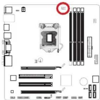
Placeat the 45b fan does not board the mainboard.
-
with the fan's wires facing towards the fan connector and the hooks matching the holes on the mainboard.
text_image
Diagram of a computer motherboard layout with labeled components and a warning symbol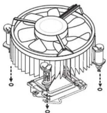
natural_image
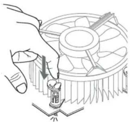
Technical line drawing of a CPU fan with cooling fins and heatsink (no text or symbols)- In a short dose main board is taken until the four clips get wedged into the holes on the mainboard. Press the four hooks down to fasten the cooler. As each hook locks into position a click should be heard.
natural_image
Illustration of a hand using a screwdriver to adjust the CPU fan (no text or symbols present)- the clip-ends have been properly locked in place.
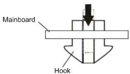
text_image
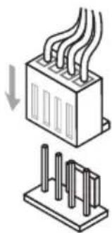
Mainboard Hook- Finally, attach the CPU fan cable to the CPU fan connector on the mainboard.
natural_image
Diagram showing a heat exchanger or cooling unit with cooling fins and a base with vertical slots (no text or symbols)Important
- Do not touch the CPU socket pins.
- Confirm that the CPU cooler has formed a tight seal with the CPU before booting your system.
- Whenever the CPU is not installed, always protect the CPU socket pins by covering the socket with the plastic cap.
- Please refer to the documentation in the CPU cooler package for more details about CPU cooler installation.
Mounting Screw Holes
When installing the mainboard, first install the necessary mounting stands required for a mainboard on the mounting plate in your computer case. If there is an I/O back plate that came with the computer case, please replace it with the I/O backplate that came with the mainboard package. The I/O backplate should snap easily into the computer case without the need for any screws. Align the mounting plate's mounting stands with the screw holes on the mainboard and secure the mainboard with the screws provided with your computer case. The locations of the screw holes on the mainboard are shown below. For more information, please refer to the manual that came with the computer case.
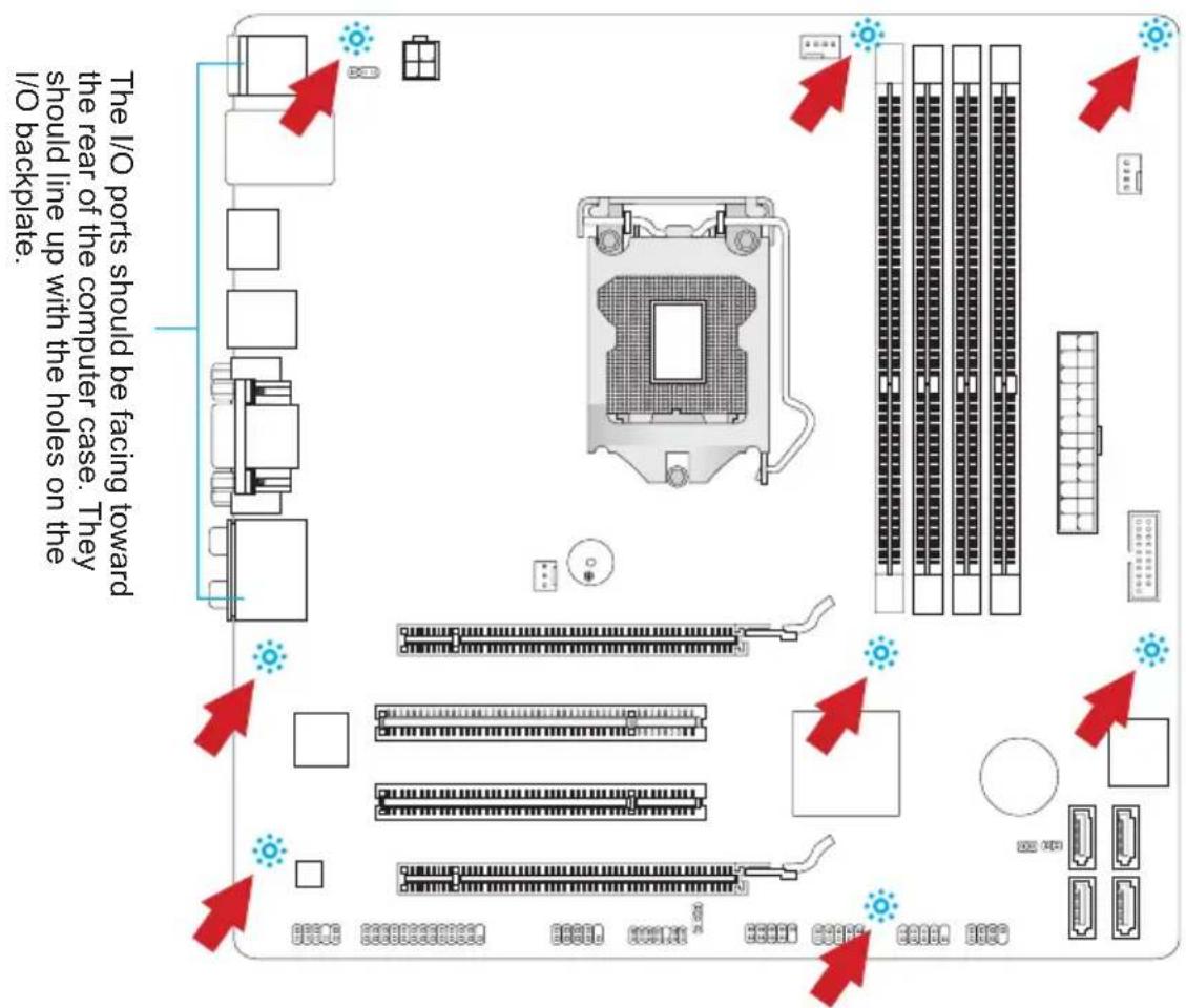
text_image
The I/O ports should be facing toward the rear of the computer case. They should line up with the holes on the I/O backplate.
Important
• Install the mainboard on a flat surface free from unnecessary debris.
- To prevent damage to the mainboard, any contact between the mainboard circuitry and the computer case, except for the mounting stands, is prohibited.
- Please make sure there are no loose metal components on the mainboard or within the computer case that may cause a short circuit of the mainboard.
Power Supply
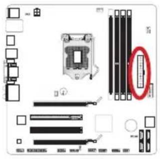
JPWR1: ATX 24-pin Power Connector
This connector allows you to connect an ATX 24-pin power supply. To connect the ATX 24-pin power supply, align the power supply cable with the connector and firmly press the cable into the connector. If done correctly, the clip on the power cable should be hooked on the mainboard's power connector.
text_image
Diagram of a computer motherboard with labeled components and a magnified view highlighting a specific component.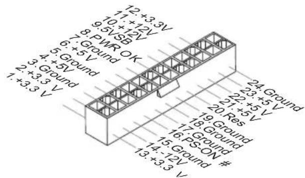
text_image
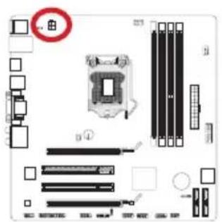
12 +3.3V 11 +12V 9.5VSB 7. Ground OK 6. +5V 5. Ground 4. +5V 3. Ground 2. +3.3V 1. +3.3V 24 Ground 23 +5V 22 +5V 20 Res 19 Ground 18 Ground 17 Ground 16 PS-ON # 15 Ground # 14 -12V 13 +3.3VJPWR2: ATX 4-pin Power Connector
This connector provides 12V power to the CPU.
text_image
Diagram of a computer motherboard with labeled components and a highlighted CPU socket component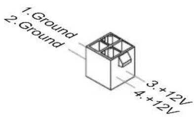
text_image
1. Ground 2. Ground 3 +12V 4 +12V
Important
Make sure that all the power cables are securely connected to a proper ATX power supply to ensure stable operation of the mainboard.
Memory
These DIMM slots are used for installing memory modules. For more information on compatible components, please visit http://www.msi.com/service/test-report
DDR3
240-pin, 1.5V
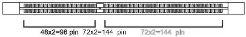
text_image
48x2=96 pin 72x2=144 pin 72x2=144 pinDual-Channel mode Population Rule
In Dual-Channel mode, the memory modules can transmit and receive data with two data bus channels simultaneously. Enabling Dual-Channel mode can enhance system performance. The following illustrations explain the population rules for Dual-Channel mode.
①
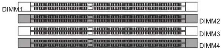
text_image
DIMM1 DIMM2 DIMM3 DIMM4②
DIMM2
DIMM3
DIMM4
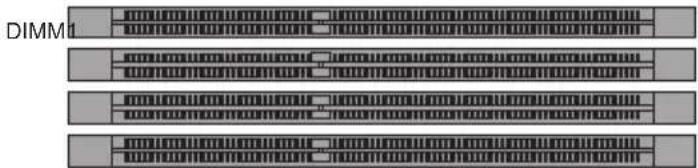
text_image
DIMM1
text_image
Installed Empty
Important
- DDR3 memory modules are not interchangeable with DDR2, and the DDR3 standard is not backward compatible. Always install DDR3 memory modules in DDR3 DIMM slots.
- To ensure system stability, memory modules must be of the same type and density in Dual-Channel mode.
- Due to chipset resource usage, the system will only detect up to 31+ GB of memory (not full 32 GB) when all DIMM slots have 8GB memory modules installed.
Installing Memory Modules
- Unlock the DIMM slot by pushing the mounting clips to the side. Vertically insert the memory module into the DIMM slot. The memory module has an off-center notch on the bottom that will only allow it to fit one way into the DIMM slot.
- Push the memory module deep into the DIMM slot. The plastic clips at each side of the DIMM slot will automatically close when the memory module is properly seat and an audible click should be heard.
- Manually check if the memory module has been locked in place by the DIMM slot's side clips.
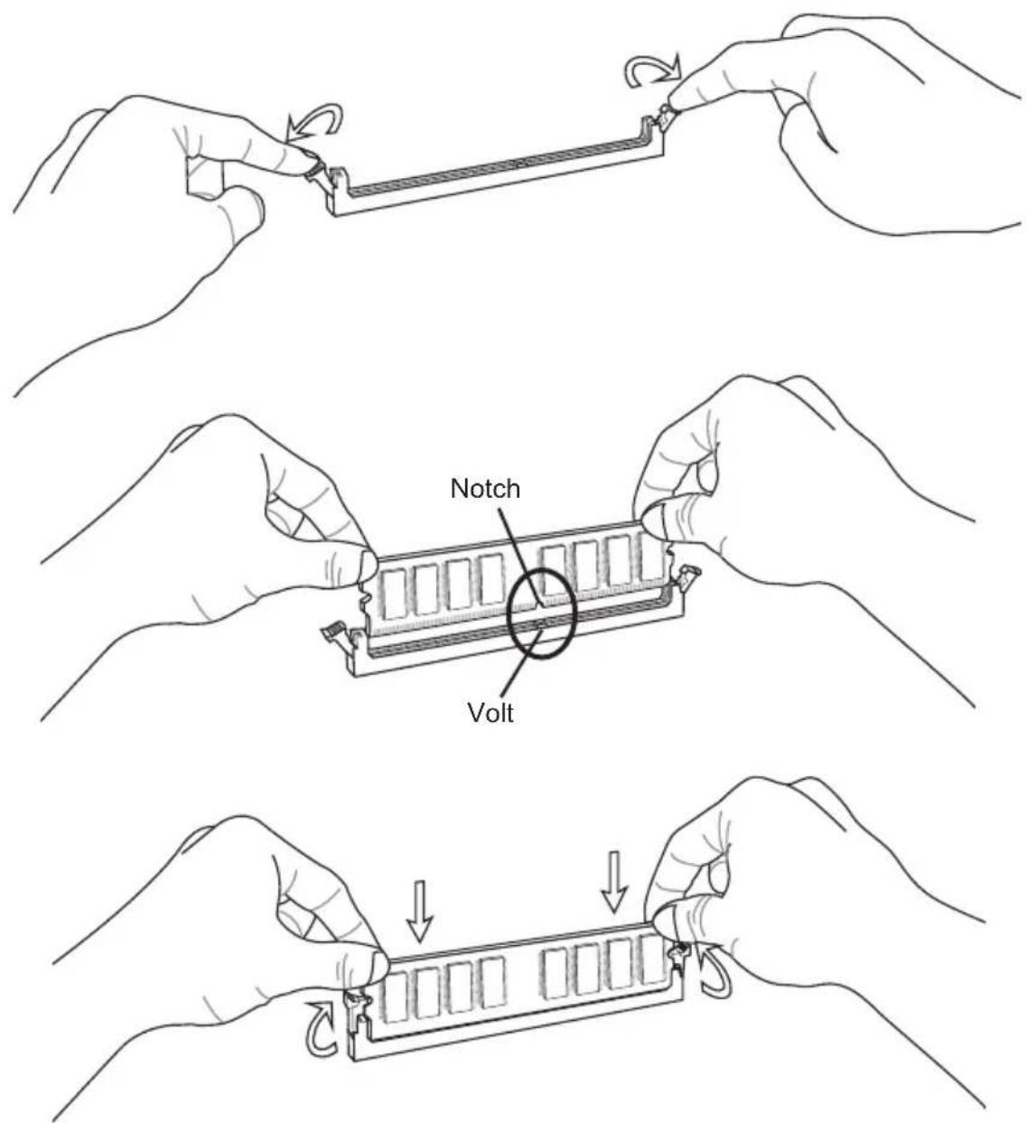
text_image
Notch VoltExpansion Slots
This mainboard contains numerous ports for expansion cards, such as discrete graphics or audio cards.
PCIe (Peripheral Component Interconnect Express) Slot
The PCIe slot supports the PCIe interface expansion card.
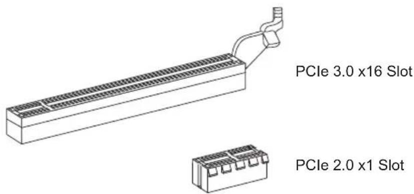
text_image
PCIe 3.0 x16 Slot PCIe 2.0 x1 SlotPCI (Peripheral Component Interconnect) Slot
The PCI slot supports additional LAN, SCSI, USB, and other add-on cards that comply with PCI specifications.
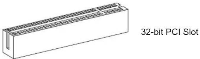
text_image
32-bit PCI Slot
Important
When adding or removing expansion cards, always turn off the power supply and unplug the power supply power cable from the power outlet. Read the expansion card's documentation to check for any necessary additional hardware or software changes.
PCI Interrupt Request Routing
IRQ, or interrupt request lines, are hardware lines over which devices can send interrupt requests to the processor. The PCI IRQ pins are typically connected to the PCI bus pins as followed:
| Order1 Order2 Order3 Order4 | |
| PCI Slot1 INT | A# INT B# INT C# INT D# |
| PCI Slot2 INT | B# INT C# INT D# INT A# |
Video/ Graphics Cards
If available, this mainboard takes advantage of the CPU's integrate graphics processor, but discrete video cards can be installed by way of the mainboard's expansion slots. Adding on one or more discrete video cards will significantly boost the system's graphics performance. For best compatibility, MSI graphics cards are recommended.
Single Video Card Installation
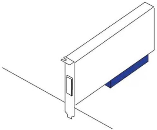
- Determine what type of expansion slot(s) the video card will use. Locate the expansion slot(s) on the mainboard. Remove any protective expansion slot covers from the computer case.
- Line up the video card on top of the expansion slot(s) with the display ports facing out of the computer case. For a single video card installation, using the PCI_E1 slot is recommended.
- Push the video card into its expansion slot(s). Depending on the expansion slot(s) used, there should be clip(s) on the expansion slot(s) that will lock in place.
- If needed, screw the edge of the graphics card to the computer case. Some video cards might require a power cable directly from the power supply.
- Please consult your video card's manual for further instructions regarding driver installation or other special settings.
natural_image
Isometric line drawing of a mechanical component with a blue tab and mounting bracket (no text or symbols)AMD CrossFire™ (Multi-GPU) Technology
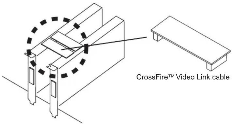
AMD CrossFire™ is a multi-GPU performance gaming platform. By linking together two or more discrete GPUs, CrossFire™ can significant improve system graphics performance. It allows the ability to scale a system's graphics power as needed, making it the most scalable gaming platform. This mainboard will automatically detect CrossFire™ technology and make changes in the BIOS as needed. Follow the instructions below to ensure a successful two-way CrossFire™ installation.
- Install two AMD Radeon™ HD graphics cards into the PCI_E1 & PCI_E2 expansion slots.
- With the two cards installed, two CrossFire™ Video Link cable are required to connect the graphics cards. Attach one side of the cable on each of the cards by way of the metal contacts (please refer to the picture below). Please note that although two graphics cards have been installed, only the display ports on the graphics card installed in the first PCIe x16 slot will work. All displays should be connected to this graphics card.
text_image
CrossFire™ Video Link cable
Important
- Please ensure that all graphics cards used in CrossFire™ mode are of the same brand and specifications. For best compatibility with the mainboard, MSI graphics cards are recommended.
- Make sure to connect an adequate power supply to the power connectors on the graphics cards to ensure stable operation.
-
Only Windows® XP with Service Pack 2 (SP2), Windows™ XP Professional x64 Edition, Windows™ Vista, & Windows™ 7 will support CrossFire™ mode.
-
Boot up the computer and install the drivers and software included in your video card package. For more information, please refer to the manual that came with your video card.
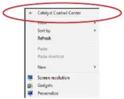
- After all of the hardware and software has been properly installed, reboot the system. After entering the operating system (OS), right click on the desktop and choose the "Catalyst Control Center II".
text_image
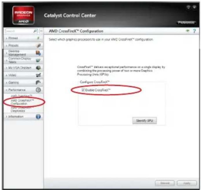
Catalyst Control Center View Sort by Refresh Paste Paste shortcut New Screen resolution Gadgets Personalize- The CrossFire™ setting must be enabled to allow CrossFire™ mode to operate. The follow screen appears in the Catalyst Control Center II. Depending on your operating system, the screen may look different.
text_image
Catalyst Control Center AMD CrossFireX™ Configuration Select which graphics processors to use in your AMD CrossFireX™ configuration. CrossFireX™ delivers exceptional performance on a single display by combining the processing power of two or more Graphics Processing Units (IPIUs). Config: CrossFireX™ ✓ Enable CrossFireX™ Identify GPU AML CrossFireX™ AMD CrossFireX™ Configuration AMD CrossFireX™ AML CrossFireX™ Configuration AMD CrossFireX™ AML CrossFireX™ AML CrossFireX™ AML CrossFireX™ AML CrossFireX™ AML CrossFireX™ AML CrossFireX™ AML CrossFireX™ AML CrossFireX™ AML CrossFireX™ AML CrossFireX™ AML CrossFireX™ AML CrossFireX™ AML CrossFireX™ AML CrossFireX™ AML CrossFireX™ AML CrossFireX™ AML CrossFireX® AML CrossFireX® AML CrossFireX® AML CrossFireX® AML CrossFireX® AML CrossFireX® AML CrossFireX® AML CrossFireX® AML CrossFireX® AML CrossFireX® AML CrossFireX® AML CrossFireX® AML CrossFireX® AML CrossFireX® AML CrossFireX® AML CrossFireX® AML CrossFireX® AML Cross FireX® AML Cross FireX® AML Cross FireX® AML Cross FireX® AML Cross FireX® AML Cross FireX® AML Cross FireX® AML Cross FireX® AML Cross FireX® AML Cross FireX® AML Cross FireX® AML Cross FireX® AML Cross FireX® AML Cross FireX® AML Cross FireX® AML Cross FireX® AML Cross FireX® AMG10000000000000000000000000000000000000000000000000000000000000000000000000000000000000000000000000000
Important
A CrossFire ^TM system has four possible display modes:
- SuperTiling
- Scissor Mode
• Alternate Frame Rendering
• Super Anti-aliasing.
For more details, please consult the graphics card manual.
Internal Connectors
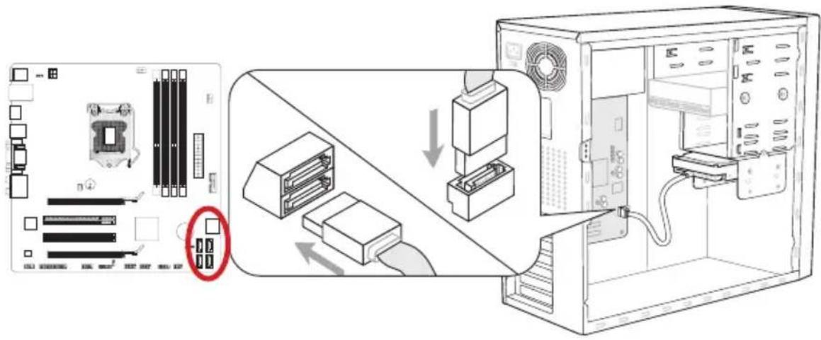
SATA1\~6: SATA Connector
This connector is a high-speed SATA interface port. Each connector can connect to one SATA device. SATA devices include disk drives (HDD), solid state drives (SSD), and optical drives (CD/ DVD/ Blu-Ray).
text_image
Diagram illustrating computer system components including CPU socket, drive, and internal server interface with labeled ports and connection arrows.* The MB layout in this figure is for reference only.
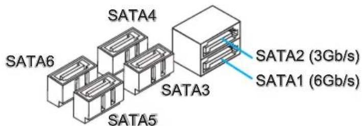
text_image
SATA4 SATA6 SATA5 SATA3 SATA2 (3Gb/s) SATA1 (6Gb/s)SATA1 (6Gb/s, by Intel® B75)
SATA2\~6 (3Gb/s, by Intel® B75)

Important
- Many SATA devices also need a power cable from the power supply. Such devices include disk drives (HDD), solid state drives (SSD), and optical drives (CD / DVD / Blu-Ray). Please refer to the device's manual for further information.
- Many computer cases also require that large SATA devices, such as HDDs, SSDs, and optical drives, be screwed down into the case. Refer to the manual that came with your computer case or your SATA device for further installation instructions.
- Please do not fold the SATA cable at a 90-degree angle. Data loss may result during transmission otherwise.
- SATA cables have identical plugs on either sides of the cable. However, it is recommended that the flat connector be connected to the mainboard for space saving purposes.
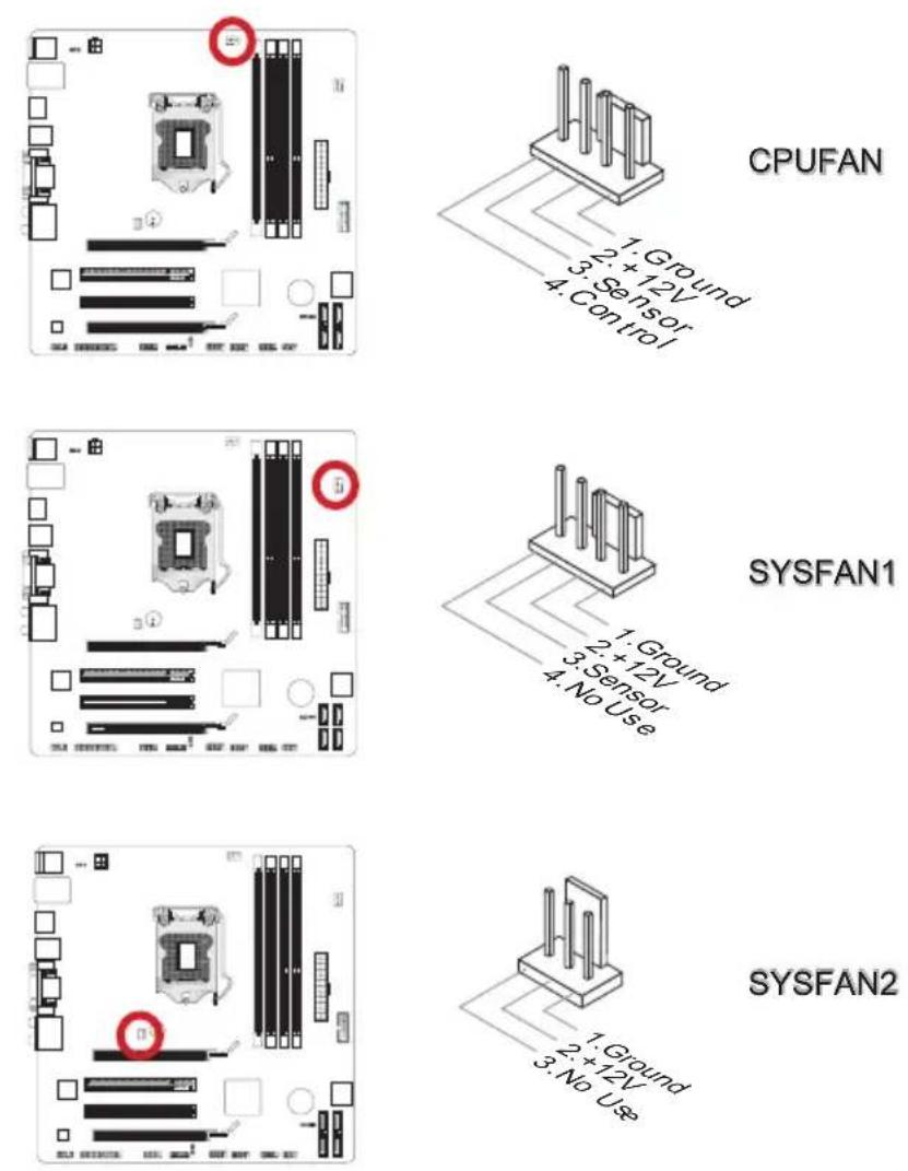
CPUFAN,SYSFAN1\~2: Fan Power Connectors
The fan power connectors support system cooling fans with +12V. If the mainboard has a System Hardware Monitor chipset on-board, you must use a specially designed fan with a speed sensor to take advantage of the CPU fan control. Remember to connect all system fans. Some system fans may not connect to the mainboard and will instead connect to the power supply directly. A system fan can be plugged into any available system fan connector.

Important
- Please refer to your processor's official website or consult your vendor to find recommended CPU cooling fans.
- The CPUFAN connector supports Smart Fan Control with linear mode. The Control Center II utility can be installed to automatically control the fan speeds according to the CPU's temperature.
- If there are not enough ports on the mainboard to connect all system fans, adapters are available to connect a fan directly to a power supply.
- Before first boot up, ensure that there are no cables impeding any fan blades.
JFP1, JFP2: Front Panel Connectors
These connectors connect to the front panel switches and LEDs. The JFP1 connector is compliant with the Intel® Front Panel I/O Connectivity Design Guide. When installing the front panel connectors, please use the enclosed mConnectors to simplify installation. Plug all the wires from the computer case into the mConnectors and then plug the mConnectors into the mainboard.
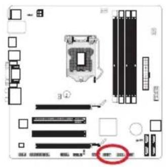
text_image
Diagram of a computer motherboard showing CPU socket, RAM slots, and memory drive components with a highlighted red circle indicating a specific area.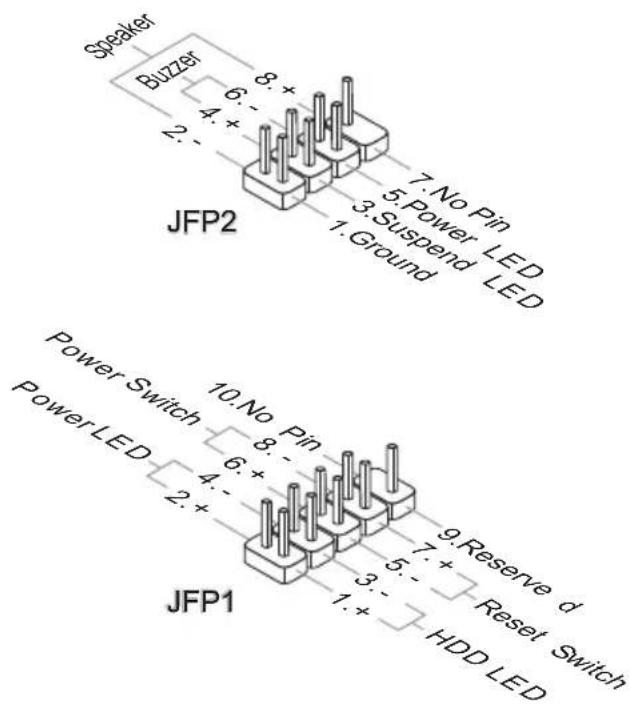
text_image
Speaker Buzzer JFP2 7. No Pin 5. Power LED 3. Suspend LED 1. Ground Power Switch Power LED JFP1 10. No Pin 8. - 6. + 4. - 2. + 9. Reserve d 5. + Reset Switch 3. - 1. + HDD LED
Important
- On the connectors coming from the case, pins marked by small triangles are positive wires. Please use the diagrams above and the writing on the mConnectors to determine correct connector orientation and placement.
- The majority of the computer case's front panel connectors will primarily be plugged into JFP1.
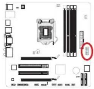
JUSB3: USB 3.0 Expansion Connector
The USB 3.0 port is backwards compatible with USB 2.0 devices. It supports data transfer rates up to 5Gbits/s (SuperSpeed).
text_image
Diagram of a computer motherboard showing CPU socket, RAM slots, and memory drive components with a highlighted red circle indicating a specific area.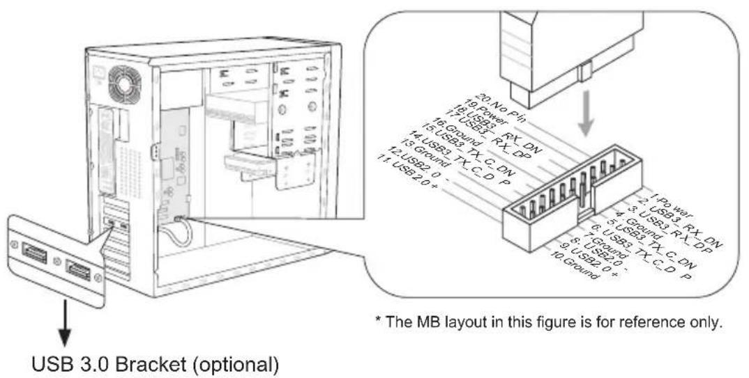
text_image
USB 3.0 Bracket (optional) * The MB layout in this figure is for reference only.
Important
- Note that the VCC and GND pins must be connected correctly to avoid possible damage.
- To use a USB 3.0 device, you must connect the device to a USB 3.0 port through an optional USB 3.0 compliant cable.
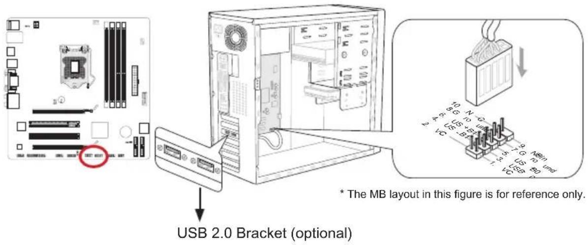
JUSB1\~2: USB 2.0 Expansion Connectors
This connector is designed for connecting high-speed USB peripherals such as USB HDDs, digital cameras, MP3 players, printers, modems, and many others.
text_image
USB 2.0 Bracket (optional) * The MB layout in this figure is for reference only.
Important
Note that the VCC and GND pins must be connected correctly to avoid possible damage.
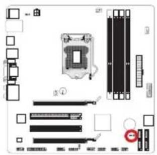
JCI1: Chassis Intrusion Connector
This connector connects to the chassis intrusion switch cable. If the computer case is opened, the chassis intrusion mechanism will be activated. The system will record this intrusion and a warning message will flash on screen. To clear the warning, you must enter the BIOS utility and clear the record.
text_image
Diagram of a computer motherboard layout with labeled components and connectors
text_image
2. Ground 1. CINTRUJAUD1: Front Panel Audio Connector
This connector allows you to connect the front audio panel located on your computer case. This connector is compliant with the Intel ^ Front Panel I/O Connectivity Design Guide.

text_image
10. Head Phone Detection 8. No Pin 6. MIC Detection 4. NC 2. Ground 9. Head Phone L 7. SENSE SEN D 5. Head Phone R 3. MIC R 1. MIC LJTPM1: TPM Module Connector
This connector connects to a TPM (Trusted Platform Module). Please refer to the TPM security platform manual for more details and usages.
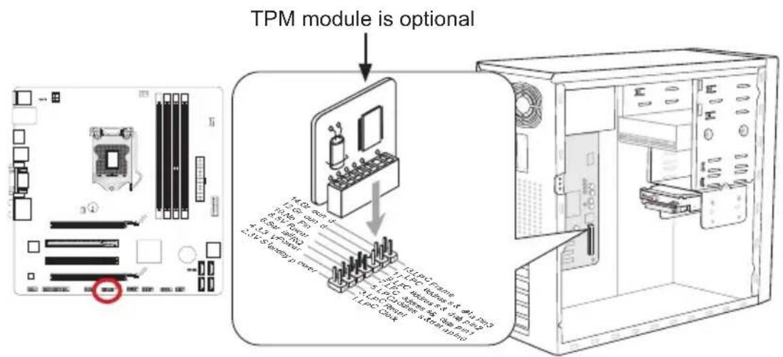
text_image
TPM module is optional 1.0 GB bus cl 1.5 GB bus 2.0 GB bus 3.0 GB bus 4.5 GB bus 5.0 GB bus 6.0 GB bus 7.0 GB bus 8.0 GB bus 9.0 GB bus 10.0 GB bus 11.0 GB bus 12.0 GB bus 13.0 GB bus 14.0 GB bus 15.0 GB bus 16.0 GB bus 17.0 GB bus 18.0 GB bus 19.0 GB bus 20.0 GB bus 21.0 GB bus 22.0 GB bus 23.0 GB bus 24.0 GB bus 25.0 GB bus 26.0 GB bus 27.0 GB bus 28.0 GB bus 29.0 GB bus 30.0 GB bus 31.0 GB bus 32.0 GB bus 33.0 GB bus 34.0 GB bus 35.0 GB bus 36.0 GB bus 37.0 GB bus 38.0 GB bus 39.0 GB bus 40.0 GB bus 41.0 GB bus 42.0 GB bus 43.0 GB bus 44.0 GB bus 45.0 GB bus 46.0 GB bus 47.0 GB bus 48.0 GB bus 49.0 GB bus 50.0 GB bus* The MB layout in this figure is for reference only.
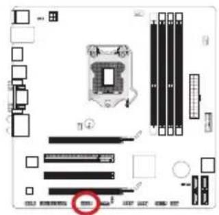
JCOM1: Serial Port Connector
This connector is a 16550A high speed communication port that sends/receives 16 bytes FIFOs. You can attach a serial device.
text_image
Diagram of a computer motherboard showing CPU socket, RAM slots, and memory connections with a red circle highlighting a specific component.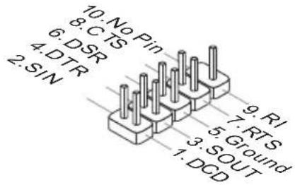
text_image
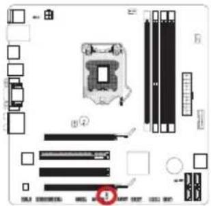
10: No Pin 8: CTS 6: DSR 4: DTR 2: SIN 9: RI 7: RTS 5: Ground 3: SOUT 1: DCDJLPT1: Parallel Port Connector
This connector is used to connect an optional parallel port bracket. The parallel port is a standard printer port that supports Enhanced Parallel Port (EPP) and Extended Capabilities Parallel Port (ECP) mode.
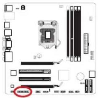
text_image
Diagram of a computer motherboard with labeled components and a highlighted 'COMEXED' button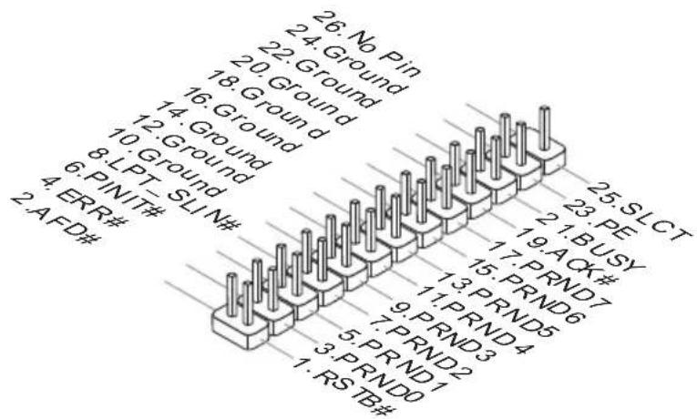
text_image
26. No Pin 24. Ground 22. Ground 18. Ground 16. Ground 14. Ground 10. Ground 8. LPT-SLIN# 4. ERR# 2. AFD# 25. SLCT 23. PE 21. BUSY 19. ACK# 17. PRND7 15. PRND6 13. PRND5 9. PRND4 7. PRND3 5. PRND2 3. PRND1 1. RSTB# 1. PRND0Jumper
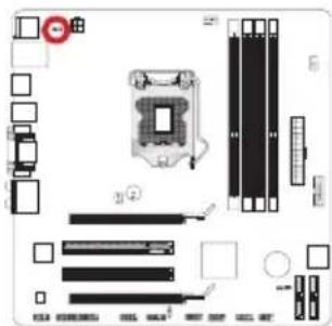
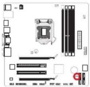
JUSB\_PW1\~2: USB power Jumper
These jumpers are used to select USB ports powered by VCC5 or 5VSB. Set to 5VSB if you want them provide power in standby mode.
text_image
Diagram of a computer motherboard with labeled components and a highlighted indicator for component 1JUSB_PW1
(for back panel USB connectors)

Close 1-2
Keep USB power to VCC5 (default)

Close 2-3
Keep USB power to 5VSB
text_image
Exploded view diagram of a computer motherboard with labeled components and connectorsJUSB_PW2
(for on-board USB connectors)
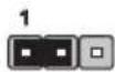
Close 1-2
Keep USB power to VCC5 (default)

Close 2-3
Keep USB power to 5VSB

Important
If you set the jumper to 5VSB, the power supply must be able to provide at least 2A currents.
JBAT1: Clear CMOS Jumper
There is CMOS RAM onboard that is external powered from a battery located on the mainboard to save system configuration data. With the CMOS RAM, the system can automatically boot into the operating system (OS) every time it is turned on. If you want to clear the system configuration, set the jumpers to clear the CMOS RAM.
text_image
Diagram of a computer motherboard layout with labeled components and connectors
text_image
1 Keep Data Clear Data
Important
You can clear the CMOS RAM by shorting this jumper while the system is off. Afterwards, open the jumper. Do not clear the CMOS RAM while the system is on because it will damage the mainboard.

natural_image
Abstract illustration of a globe with orbiting lines and abstract light effects (no text or symbols)Chapter 2
BIOS Setup
CLICK BIOS II is a revolutionary UEFI interface that allows you to setup and configure your system for optimum use. Using your mouse and keyboard, users can change BIOS settings, monitor CPU temperature, select the boot device priority and view system information such as the CPU name, DRAM capacity, the OS version and the BIOS version. Users can import and export parameter data for backup or for sharing with friends. By connecting to the Internet within CLICK BIOS II, users can browse webpages, check mail and use Live Update iyour system.
Entering
Power on the computer and the system will start the Power On Self Test (POST) process. When the message below appears on the screen, please key to enter CLICK BIOS II:
Press DEL key to enter Setup Menu, F11 to enter Boot Menu
If the message disappears before you respond and you still need to enter CLICK BIOS II, restart the system by turning the computer OFF then back ON or pressing the RESET button. You may also restart the system by simultaneously pressing

Important
The items under each BIOS category described in this chapter are under continuous update for better system performance. Therefore, the description may be slightly different from the latest BIOS and should be held for reference only.
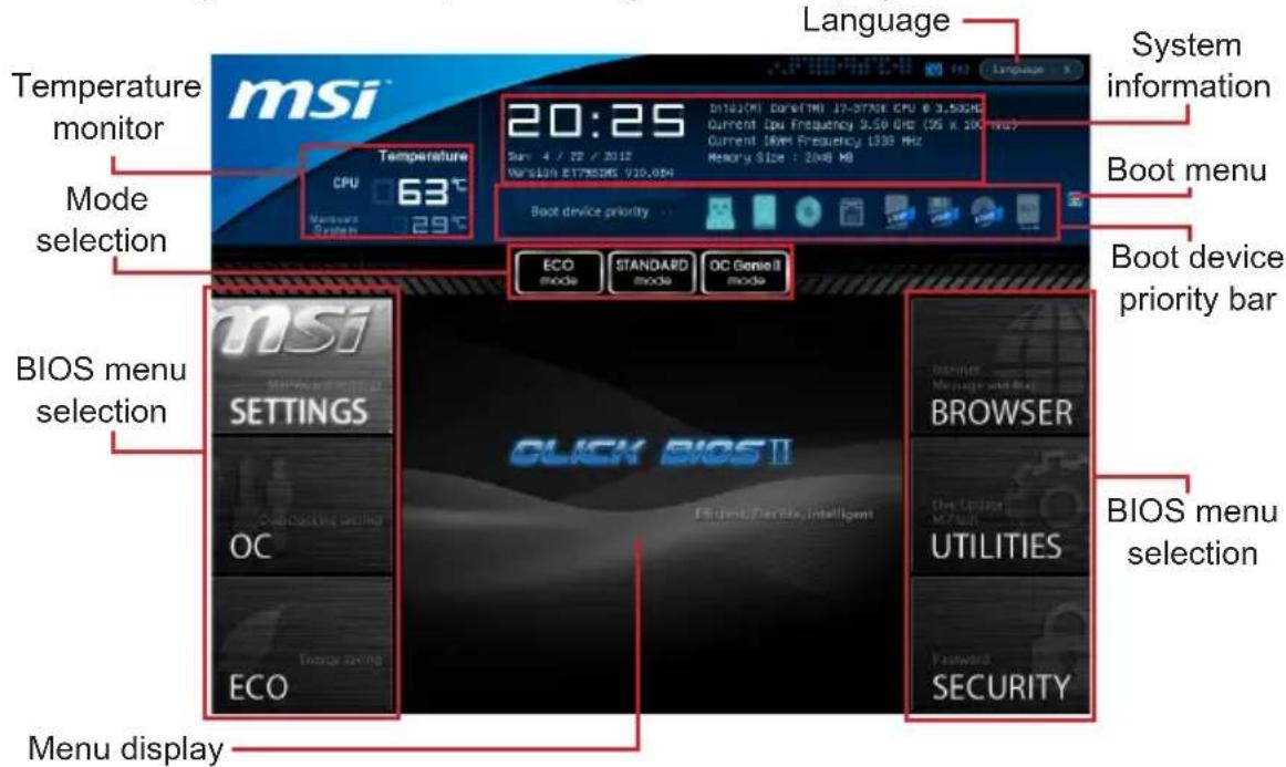
Overview
After entering CLICK BIOS II, the following screen is displayed.
text_image
msi Temperature monitor Mode selection BIOS menu selection Menu display Temperature CPU 63°C Macronos System 29°C 20:25 Date: 4 / 22 / 2017 Version: ET7850K5 V10.0M Boot device priority ECO mode STANDARD mode OC Genre II mode CLICK BIOS II BROWSER The Luggage Mode UTILITIES Security System information Boot menu Boot device priority bar BIOS menu selection
Important
The pictures in this guide are for reference only and may vary from the product you purchased. Please refer to the actual screens of your system for detailed information.
▶ Temperature monitor
This block shows the temperature of the processor and the mainboard.
▶ System information
This block shows the time, date, CPU name, CPU frequency, DRAM frequency, DRAM capacity and the BIOS version.
▶ BIOS menu selection
The following options are available:
- SETTINGS - Use this menu to specify your settings for chipset features and boot devices.
- OC - This menu contains items of the frequency and voltage adjustments. Increasing the frequency can get better performance, however high frequency and heat can cause instability, we do not recommend general users to over-clock.
■ ECO - This menu is related to energy-saving settings.
■ BROWSER - This feature is used to enter the MSI Winki web browser.
■ UTILITIES - This menu contains utilities for backup and update. - SECURITY - The security menu is used to keep unauthorized people from making any changes to the settings. You can use these security features to protect your system.
▶ Boot device priority bar
You can move the device icons to change the boot priority.
▶ Boot menu
This button is used to open a boot menu. Click the item to boot the system from the device instantly.
▶ Mode selection
This feature allows you to load presets of energy saving or overclocking.
▶ Menu display
This area provides BIOS settings and information to be configured.
▶ Language
This allows you to select the language of the BIOS setting.
Boot device priority bar
This bar shows the priority of the boot devices. The lighted icons indicate that the devices are available.

text_image
Boot device priority High priority Low priorityClick and draw the icon to left or right to specify the boot priority.
■ Boot device icon list

USB Drive

Hard disk drive

Optical disk

LAN

BEV

USB hard
disk drive

USB
floppy

USB optical drive

UEFI

Disable
Operation
CLICK BIOS II allows you to control BIOS settings with the mouse and the keyboard. The following table lists and describes the hot keys and the mouse operations.
| Hot key Mouse Description | Description | |
| <↑↓→←> |  Move the cursor Move the cursor | Select Item |
 Click/ Double-click the left button Click/ Double-click the left button | Select Icon/ Field | |
 Click the right button Click the right button | Jump to the Exit menu or return to the previous from a submenu | |
| <+> Increase the numeric value or make changes | ||
| <-> Decrease the numeric value or make changes | ||
| General HelpSpecifications | ||
| Enter Memory-Zoptimized defaults | ||
| OC Profile Load From USB | ||
| OC Profile Save to USB | ||
| Save Change and Reset | ||
| Save a screenshot to a FAT/FAT32 USB drive | ||
Sub-Menu
If you find a point symbol to the left of certain fields, that means a sub-menu can be launched for ad-
Overclocking Profiles
CPU Specifications
ditional options. You can use the arrow keys or mouse to highlight the field and press
General Help
The General Help screen lists the appropriate keys to use for navigation. You can call up this screen from any menu by simply pressing
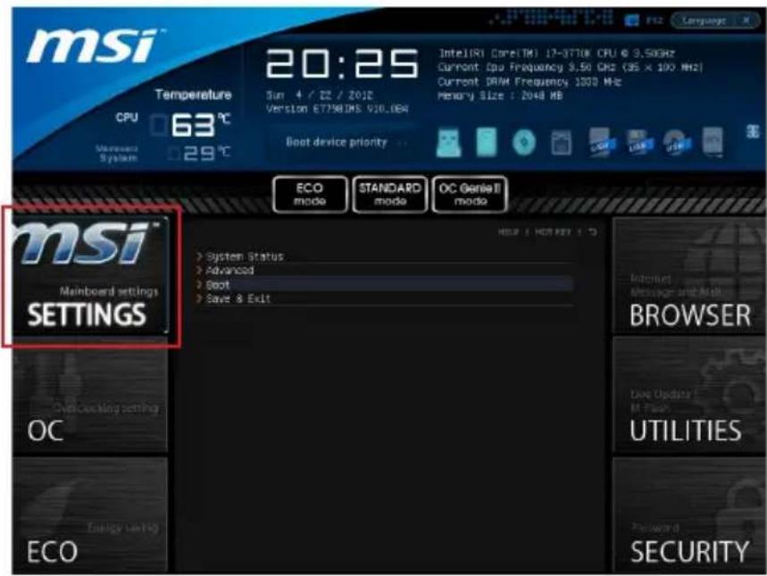
SETTINGS
text_image
msi Temperature CPU 63 °C 20:25 Sun 4 / 22 / 2012 Version ET798DMS V30.08A Boot device priority ECO mode STANDARD mode OC Genel II mode msi™ Mainboard settings SETTINGS System Status Advanced Boot Save & Exit OC Energy saving ECO Internet Message and Mail BROWSER Live Update M Flash UTILITIES Password SECURITYSystem Status
▶ System Date
This allows you to set the system date that you want (usually the current date).
The format is
day Day of the week, from Sun to Sat, determined by BIOS.
Read-only.
month The month from Jan. through Dec.
date The date from 1 to 31 can be keyed by numeric function keys.
year The year can be adjusted by users.
▶ System Time
This allows you to set the system time that you want (usually the current time). The time format is
▶ SATA Port1\~6
Shows devices connected to specific SATA ports.

Important
If your device is not displayed, turn off computer and re-check SATA cable and power cable connections to the device.
▶ System Information
Shows detailed system information, including CPU type, BIOS version, and Memory (read only).
Advanced
▶ PCI Subsystem Settings
Press
▶PCIE GEN3
This item is used to enable/ disable the PCIe generation 3 support.
▶ PCI Latency Timer
Controls how long each PCI device can hold the bus before another takes over. When set to higher values, every PCI device can conduct transactions for a longer time and thus improve the effective PCI bandwidth.
▶ ACPI Settings
Press
▶ACPI Standby State
Specifies the power saving mode for ACPI function
[S1] Sleep Mode. Hardware remains on.
[S3] Suspend to RAM. Turns off hardware. (Recommended)
▶ Power LED
Configures how the system uses power LEDs on the case to indicate sleep/suspend state.
[Dual] The power LED changes its color to indicate the sleep/suspend state.
[Blinking] The power LED blinks to indicate the sleep/suspend state.
▶ Integrated Peripherals
Press
▶ Onboard LAN Controller
This item allows you to enable/ disable the onboard LAN controller.
▶ LAN Option ROM
This item is used to decide whether to invoke the Boot ROM of the onboard LAN.
▶ Network Stack
This item is used to enable/ disable UEFI network stack.
▶Ipv4 PXE Support
This item appears when you set "Enabled" in [Network Stack] field and is used to enable/ disable the lpv4 PXE boot support.
▶Ipv6 PXE Support
This item appears when you set "Enabled" in [Network Stack] field and is used to enable/ disable the lpv6 PXE boot support.
▶SATA Mode
This item is used to specify IDE/AHCI mode for SATA port.

Important
You cannot switch between AHCI and IDE if you already have your operating system installed. If you have installed your OS using AHCI and you clear your BIOS/reset to
default settings, you will need to change this function back to AHCI to ensure proper functionality.
▶SATA1\~6 Hot Plug
These items are used to enable/ disable the SATA ports hot plug support.
▶HD Audio Controller
This item allows you to enable/ disable the HD audio controller.
HPET
The HPET (High Precision Event Timers) is a component that is part of the chipset. You can enable it, and will provide you with the means to get to it via the various ACPI methods.
▶ Integrated Graphics Configuration
Press
▶ Initiate Graphic Adapter
Choose which adapter you wish to make the primary option
[IGD] Integrated Graphics Display
[PEG] PCI-Express Graphics Device
▶ Integrated Graphics Share Memory
The system shares memory to the onboard graphics. This setting controls the exact memory size shared to the onboard graphics.
▶DVMT Memory
Specify the size of DVMT memory to allocate for video memory.
▶IGD Multi-Monitor
Enables both integrated and discrete graphics at the same time. When disabled, it will default to Initiated Graphics Adapter selection.
▶ Intel(R) Rapid Start Technology
Press
▶Intel(R) Rapid Start Technology
This item is used to enable/ disable the Intel Rapid Start technology.
▶ USB Configuration
Press
▶USB Controller
This item allows you to enable/ disable the integrated USB 2.0 controller.
▶Legacy USB Support
Enable or disable support for USB keyboards, mice and floppy drives. You will be able to use these devices with operating systems that do not support USB.
▶ Super IO Configuration
Press
▶ Serial(COM) Port 0 Configuration
Press
▶ Serial (COM) Port0
This item allows you to enable/ disable the serial port.
▶ Serial (COM) Port0 Settings
Select an address and corresponding interrupt for the serial port.
▶Parallel(LPT) Port Configuration
Press
▶ Parallel(LPT) Port
This item allows you to enable/ disable the parallel port.
▶ Parallel(LPT) Port Settings
Select an address and corresponding interrupt for the parallel port.
▶ Device Mode
Select a device mode for the parallel port.
▶ Hardware Monitor
Press
▶CPU Smart Fan Target
Controls CPU fan speed automatically depending on the current temperature and to keep it with a specific range. If the current CPU temperature reaches the target value, the smart fan function will be activated.
▶SYS Fan1 Control
This item allows users to select how percentage of speed for the SYSFAN1.
▶CPU/ System Temperature, CPU FAN/ SYS FAN 1/2 Speed
These items show the current status of all of the monitored hardware devices/ components such as CPU temperature/ system temperature and the few fans' speeds.
▶ Intel(R) Smart Connect Configuration
Press
▶Intel(R) Smart Connect Technology
This item allows you to enable/ disable Intel® Smart Connect Technology. When you enable it, the system will be woked periodically from Sleep/Standy mode for a brief period of time to update programs.
▶ Power Management Setup
Press
▶EuP 2013
Energy Using Products Lot 6 2013 (EUP) reduces power consumption when system is off or in standby mode.
Note: When enabled, the system will not support RTC wake up event functions.
▶Restore after AC Power Loss
This item specifies whether your system will reboot after a power failure or interrupt occurs. Settings are:
[Power Off] Always leaves the computer in the power off state.
[Power On] Always leaves the computer in the power on state.
[Last State] Restore the system to the status before power failure or interrupt occurred.
▶ Wake Up Event Setup
Press
▶ Wake Up Event By
Setting to [BIOS] activates the following fields, and use the following fields to set the wake up events. Setting to [OS], the wake up events will be defined by OS.
▶Resume By RTC Alarm
The field is used to enable or disable the feature of booting up the system on a scheduled time/date.
▶ Date/ HH:MM:SS
If Resume By RTC Alarm is set to [Enabled], the system will automatically resume (boot up) on a specific date/hour/minute/second specified in these fields (using the <+> and <-> to select the date & time settings).
▶Resume By PCI or PCI-E Device
When set to [Enabled], the feature allows your system to be awakened from the power saving modes through any event on PCI/ PCIe device.
▶Resume From S3 by USB Device
The item allows the activity of the USB device to wake up the system from S3 (Suspend to RAM) sleep state.
▶Resume From S3/S4/S5 by PS/2 Mouse/ Keyboard
These items determine whether the system will be awakened from what power saving modes when input signal of the PS/2 mouse/ keyboard is detected.
Boot
▶ Full Screen Logo Display
[Enabled] The OS boots straight to the GUI without showing the POST screen, [Disabled] Shows the POST messages at boot.
▶ PCI ROM Priority
This item allows you to specify what PCI Option ROM to launch.
$$ = = \text { Boot Option Priorities } = = $$
▶ 1st\~9th Boot
These items are used to prioritize the installed boot devices.
▶ USB KEY Drive BBS Priorities/ UEFI Boot Drive BBS Priorities
▶1st\~8th Boot
These items are used to prioritize the installed USB key drives/ UEFI boot drives.
Save & Exit
▶ Discard Changes and Exit
This it is used to abandon all changes and exit setup.
▶ Save Changes and Reboot
This item is used to save changes and reboot the system.
▶ Save Changes
This item is used to save changes.
▶ Discard Changes
This item is used to abandon all changes.
▶ Restore Defaults
This item is used to load the optimized default values set by the BIOS vendor.
== Boot Override ==
The installed storage devices will appear on this menu, you can select one of them be a boot device.
▶ Built-in EFI Shell
Use this item to enter the EFI Shell.
OC
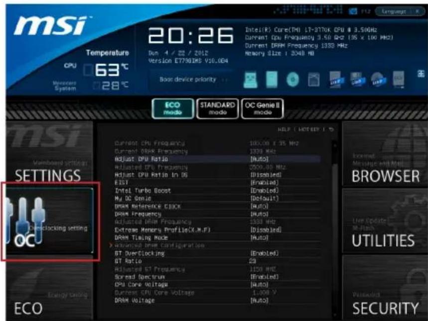
text_image
msi Temperature 63°C Version E77901MS V10.064 20:26 Intel(R) Core(TM) LT-3770K CPU @ 3.50GHz Current CPU Frequency 3.50 GHz (18 x 100 MHz) Current DRAM Frequency 1333 MHz Memory Size : 3048 MB Boot device priority ECO mode STANDARD mode OC Genie II mode INSI Vomboard setting SETTINGS Demclacking setting ECO DT Diverclicing DT Ratio Adjusted DT Frequency Spread Spectrum CPU Core Voltage Durrest CPU Core Voltage DRAM Voltage 100.00 x 35 MHz 1333 MHz [Auto] Adjusted CPU Frequency Adjusted CPU Ratio In OS EISY Intel Turbo Boost My DC Genie DRAM Reference CIOCK DRAM Frequency Adjusted DPM Frequency Extreme Memory Profile(X.M.P) DRAM Timing Mode > Advanced DPM Configuration GT Diverclicing GT Ratio Adjusted DT Frequency Spread Spectrum CPU Core Voltage Durrest CPU Core Voltage DRAM Voltage HELP (NOT NULL) BROWSER Live Update: M-Flash UTILITY Waside SECURITY
Important
• Overclocking your PC manually is only recommended for advanced users.
• Overclocking is not guaranteed, and if done improperly, can void your warranty or severely damage your hardware.
- If you are unfamiliar with overclocking, we advise you to use OC Genie for easy overclocking.
▶ Current CPU/ DRAM Frequency
These items show the current clocks of CPU and Memory speed. Read-only.
▶ Adjust CPU Ratio
Controls the multiplier that is used to determine internal clock speed of the processor. This feature can only be changed if the processor supports this function.
▶ Adjusted CPU Frequency
It shows the adjusted CPU frequency. Read-only.
▶ Adjust CPU Ratio in OS
Enable this item to allow CPU ratio changes in the OS by using MSI Control Center II.
▶ EIST
Enhanced Intel SpeedStep technology allows you to set the performance level of the microprocessor whether the computer is running on battery or AC power. This field only appears with installed CPUs that support this technology.
Intel Turbo Boost
Enables or disables Intel Turbo Boost which automatically boosts CPU performance above rated specifications (when applications requests the highest performance state of the processor).
▶ My OC Genie
This item is used to select whether OC Genie parameters are customized by user. Setting to [MSI] OC Genie will use default OC related parameters to overclock the system. Selecting [Customize] allows you to configure the following related "My OC Genie option" sub-menu manually for OC Genie.
▶ My OC Genie option
Press
▶ My OC Genie GT Overclocking
This item allows you to enable/ disable the overclocking of integrated graphics for My OC Genie function.
▶ My OC Genie GT Ratio
This item allows you to specific the GT ratio for My OC Genie function.
▶Adjusted My OC Genie GT Frequency
It shows the iGPU frequency when OC Genie is started. Read-only.
▶ DRAM Reference Clock
This item allows you to specific the DRAM Reference Clock for CPU. Please note the overclocking behavior is not guaranteed.
▶ DRAM Frequency
This item allows you to adjust the DRAM frequency. Please note the overclocking behavior is not guaranteed.
▶ Adjusted DRAM Frequency
It shows the adjusted DRAM frequency. Read-only.
▶ DRAM Timing Mode
Select whether DRAM timing is controlled by the SPD (Serial Presence Detect) EE - PROM on the DRAM module. Setting to [Auto] enables DRAM timings and the following "Advanced DRAM Configuration" sub-menu to be determined by BIOS based on the configurations on the SPD. Selecting [Link] or [Unlink] allows users to configure the DRAM timings for each channel and the following related "Advanced DRAM Configuration" sub-menu manually.
▶ Advanced DRAM Configuration
Press
▶ Command Rate
This setting controls the DRAM command rate.
▶ tCL
Controls CAS latency which determines the timing delay (in clock cycles) of starting a read command after receiving data.
▶ tRCD
Determines the timing of the transition from RAS (row address strobe) to CAS (column address strobe). The less clock cycles, the faster the DRAM performance.
▶ tRP
Controls number of cycles for RAS (row address strobe) to be allowed to pre-charge. If insufficient time is allowed for RAS to accumulate before DRAM refresh, the DRAM
may fail to retain data. This item applies only when synchronous DRAM is installed in the system.
▶ tRAS
Determines the time RAS (row address strobe) takes to read from and write to memory cell.
▶ tRFC
This setting determines the time RFC takes to read from and write to a memory cell.
▶ tWR
Determines minimum time interval between end of write data burst and the start of a pre-charge command. Allows sense amplifiers to restore data to cell.
▶tWTR
Determines minimum time interval between the end of write data burst and the start of a column-read command; allows I/O gating to overdrive sense amplifies before read command starts.
▶ tRRD
Specifies the active-to-active delay of different banks.
▶ tRTP
Time interval between a read and a precharge command.
▶ tFAW
This item is used to set the tFAW (four activate window delay) timing.
▶ tWCL
This item is used to set the tWCL (Write CAS Latency) timing.
▶tCKE
This item is used to set the Pulse Width for DRAM module.
▶ tRTL
This item is used to set Round Trip Latency settings.
▶ Advanced Channel 1/2 Timing Configuration
Press
▶ GT OverClocking
This item allows you to enable/ disable the overclocking of integrated graphics.
▶ GT Ratio
This setting controls the ratio of integrated graphics frequency to enable the integrated graphics to run at different frequency combinations.
▶ Adjusted GT Frequency
It shows the iGPU frequency. Read-only.
▶ Spread Spectrum
This function reduces the EMI (Electromagnetic Interference) generated by modulating clock generator pulses.

Important
- If you do not have any EMI problem, leave the setting at [Disabled] for optimal system stability and performance. But if you are plagued by EMI, select the value of Spread Spectrum for EMI reduction.
- The greater the Spread Spectrum value is, the greater the EMI is reduced, and the system will become less stable. For the most suitable Spread Spectrum value, please consult your local EMI regulation.
- Remember to disable Spread Spectrum if you are overclocking because even a slight jitter can introduce a temporary boost in clock speed which may just cause your overclocked processor to lock up.
▶ CPU Core Voltage/ DRAM Voltage.
These items are used to adjust the voltage of CPU and Memory.
▶ Current CPU Core Voltage/ Current DRAM Voltage
These items show current CPU/ DRAM voltage. Read-only.
▶ Overclocking Profiles
Press
▶ Overclocking Profile 1/2/3/4/5/6
Press
▶ Set Name for Overclocking Profile 1/2/3/4/5/6
Give a name by typing in this item.
▶ Save Overclocking Profile 1/2/3/4/5/6
Save the current overclocking settings to ROM for selected profile.
▶Load/ Clear Overclocking Profile 1/2/3/4/5/6
Load/ Clear the stored profile settings from ROM.
▶ OC Profile Save to USB
Save the current overclocking settings to USB flash disk.
▶ OC Profile Load from USB
Load the stored settings from USB flash disk.
▶ CPU Specifications
Press
▶CPU Technology Support
Press
▶ MEMORY-Z
Press
also access this information at any time by pressing [F5]. Press
▶DIMM1\~4 Memory SPD
Press
▶ CPU Features
Press
▶ Hyper-Threading
The processor uses Hyper-Threading technology to increase transaction rates and reduces end-user response times. The technology treats the two cores inside the processor as two logical processors that can execute instructions simultaneously. In this way, the system performance is highly improved. If you disable the function, the processor will use only one core to execute the instructions. Please disable this item if your operating system doesn't support HT Function, or unreliability and instability may occur.
▶Active Processor Cores
This item allows you to select the number of active processor cores.
▶ Limit CPUID Maximum
It is designed to limit the listed speed of the processor to older operating systems.
▶ Execute Disable Bit
Can prevent certain classes of malicious "buffer overflow" attacks where worms can try to execute code to damage your system. It is recommended you keep this enabled always.
Intel Virtualization Tech
Enhances virtualization and allows the system to act as multiple virtual systems. See Intel's official website for more information.
Intel VT-D Tech
This item is used to enable/disable the Intel VT-D technology. For further information please refer to Intel's official website.
▶ Power Technology
This item allows you to select the Intel Dynamic Power technology mode.
▶ C1E Support
Enable system to reduce CPU power consumption while idle. Not all processors support Enhanced Halt state (C1E).
▶OverSpeed Protection
Monitors current CPU draw as well as power consumption; if it exceeds a certain level, the processor automatically reduces its clock speed. For overclocking, it is recommended this feature is disabled.
Intel C-State
C-state is a power management state that detects when the system is idle and lowers power consumption accordingly.
▶Package C State limit
This field allows you to select a C-state mode.
▶Long duration power limit (W)
This field allows you to adjust the TDP power limit for the long duration.
▶Long duration maintained (s)
This field allows you to adjust the maintaining time for long duration power limit.
▶Short duration power limit (W)
This field allows you to adjust the TDP power limit for the short duration.
▶ Primary/ Secondary Plane Current value (A)
These fields allow you to adjust over current value of CPU (primary plane)/ iGPU (secondary plane) for turbo ratio.
▶ Primary/ Secondary plane turbo power limit (W)
These fields allow you to adjust the turbo power limit of CPU (primary plane)/ iGPU (secondary plane) for turbo boost.
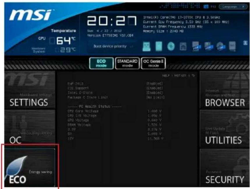
ECO
text_image
msi Temperature GPU 64°C Member System 20:27 Sun 4 / 22 / 2012 Version ET798IME Y10,CE4 Boot device priority Intel(R) Core(TM) 17-3770K CPU @ 3.5GHz Current Cou Frequency 3.50 GHz (35 x 100 MHz) Current DANA Frequency 1333 MHz Memory Size : 20MB MB ECO mode STANDARD mode OC Genel II mode MSI Main-based settings SETTINGS OC Energy saving ECO HELP | HOT SET | °C CPU 2013 CIE Support Intel O-State Package C State Unit [Enabled] (No Limit) ---- PC Health Status ---- CPU Core Voltage CPU E/O Voltage CPU Voltage DANA Voltage 0.0V 50V 12V [Enable] (Enabled) (No Limit) 1,000 V 1,050 V 9,040 V 1,520 V 3,376 V 5,000 V [1,500 V] BROWSER Live Update M-Final UTILITIES Passwd Security
Important
Once you click the "ECO" button in the pre-set area, some items in ECO menu will be fixed and un-adjustable.
▶ EuP 2013
Energy Using Products Lot 6 2013 (EUP) reduces power consumption when system is off or in standby mode.
Note: When enabled, the system will not support RTC wake up event functions.
▶ C1E Support
To enable this item to reduce the CPU power consumption while idle. Not all processors support Enhanced Halt state (C1E).
Intel C-State
C-state is a power management state that detects when the system is idle and lowers power consumption accordingly.
▶ Package C State limit
This field allows you to select a C-state mode.
▶ CPU Core Voltage/ CPU I/O Voltage/ GPU Voltage/ DRAM Voltage/ 3.3V/ 5V/ 12V
These items show the voltages. Read only.
BROWSER
Please install the MSI "Winki" application first in the Windows operating system with the MSI Driver Disc before using the browser. Then you can click the BROWSER to access the Internet, e-mail and instant messaging.

text_image
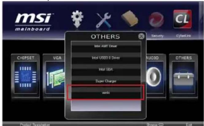
msi Temperature CPU 63°C Maintenance System 29°C 20:25 Sub 4 / 22 / 2012 Version E1798JNS V10.064 Intel(R) Core(TM) LT-3770K CPU @ 3.50Hz Current Data Frequency 3.50 MHz (35 x 100 MHz) Current Data Frequency 1333 MHz Memory Size : 2048 MB Boot device priority ECO mode STANDARD mode OC Genio II mode msi Members & Settings SETTINGS OC ECO CLICK BIOS II Efficient Flexible Intelligent BROWSER Use Update M Flash UTILITIES SecurityInstalling Winki
To install Winki, follow the steps below:
text_image
MSI mainboard OTHERS Intel AMT Driver Intel USED & Driver Intel SEA Super Charger work CHIPSET VGA AUDIO OTHERS Product Regularize Bonus CD Exit- Power on your computer and enter Windows operating system.
- Insert MSI Driver Disc into the optical drive. The setup screen will automatically appear.
- Click Driver tab.
- Click OTHERS button.
- Select Winki to start installing.
- When finished, restart your computer.
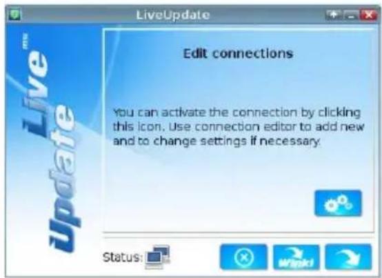
Updating the BIOS with Live Update
This section tells you how to update the BIOS by using the Live Update utility before entering Operating System. Live Update will update the BIOS automatically when connecting to the Internet. To update the BIOS with the Live Update utility:
- Click Live Update button installed).

on the BIOS UTILITIES menu. (The Winki must be
text_image
LiveUpdate Edit connections You can activate the connection by clicking this icon. Use connection editor to add new and to change settings if necessary. Status: Wnacki- Setup the connection by click the setting button if necessary.
- Click the next button
- Live Update will automatically detect the version of BIOS and download the appropriate file.
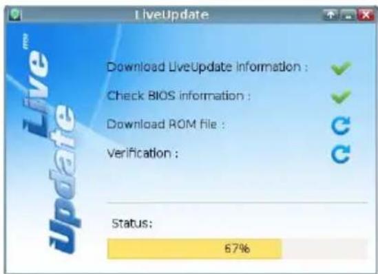
text_image
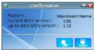
LiveUpdate Download LiveUpdate information : Check BIOS information : Download ROM file : Verification : Status: 67%Click the confirm button

to update the BIOS.5.
text_image
Confirmation Platform : Mainboard Name Current BIOS version : 1.00 Up-to-date BIOS version : 1.10
Important
Do not unplug or shut off your system during BIOS Flash. Incorrect BIOS flashing can cause the motherboard to not POST. Please ensure you have the correct version and model of your motherboard BIOS when updating.
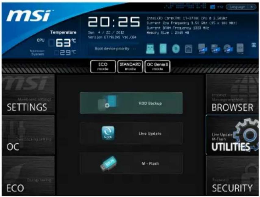
UTILITIES
text_image
msi Temperature CPU 63°C 20:25 Sim 4 / 22 / 2012 Version ET7981M8 V10.0B4 Boot device priority Intel(R) Core(TM) 17-37T0C CPU @ 3.50GHz Current CPU Frequency 3.50 MHz (35 x 100 MHz) Current DRAM Frequency 1330 MHz Memory SLze : 2048 MB ECO mode STANDARD mode OC Genie II mode HDD Backup Live Update M - Flash INSIST Message watch hit BROWSER Live Update M-Flash UTILITIES Security ECO▶ HDD Backup
Hard disk storage backups and restoring is one of the most common and important tasks. Use this utility to create an image of your HDD partitions and re-load them when necessary.

Important
The HDD Backup can't back up (/restore) image to (/from) a partition where itself was installed, so it's strongly recommended to divide HDD into 2 partitions at least (1st for OS; 2nd for data).
For HDD with single partition only, the requirements for HDD Backup are:
- An additional partition from another HDD (ex. USB HDD) for HDD Backup to back up (/restore) image to (/from) it.
- Executing Winki stored in USB flash drive/ MSI Driver Disc by pressing
to choose boot device during POST.
▶ Live Update
This tool can detect and update your BIOS online so that you won't need to spend time searching manually.

Important
HDD Backup and Live Update request Winki, please install the "Winki" software application from MSI Driver Disc in Windows first. And then you can access these two utilities by clicking their respective buttons.
▶ M-Flash
▶BIOS Boot Function
This allows you to enable/ disable the system to boot from the BIOS file inside USB drive (FAT/ 32 format only).
▶ Select one file to Boot
When the BIOS Boot function as sets to [Enabled], this item is selectable. This item allows to select particular BIOS file from the USB/ Storage (FAT/ 32 format only) drive. And the system will boot from selected BIOS file.
▶ Save BIOS to storage
Please setup a specific folder in specific USB/ Storage drive to save BIOS file from BIOS ROM chip data. Note: it only supports FAT/ 32 file system drive.
▶Select one file to update BIOS
This item allows you to select a particular BIOS file from the USB/ Storage (FAT/ 32 format only) drive for updating BIOS.
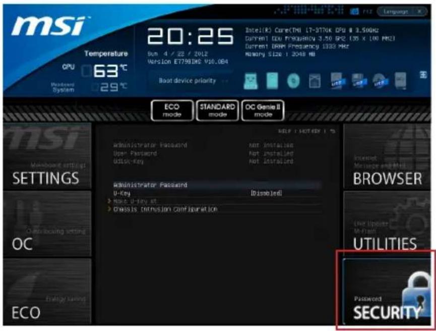
SECURITY
text_image
msi Temperature CPU 63°C Modemord System 29°C 20:25 Sun 4 / 22 / 2012 Version ET7981HS V10.084 Intel(R) Core(TM) LT-978K DPU @ 3.59Hz Current DDR Frequency 3.50 GHz (35 x 100 MHz) Current DDR Frequency 1933 MHz Memory Size: 1.3048 MB Boat device priority ECO mode STANDARD mode OC Genie II mode INSI Mainboard settings SETTINGS OC Auto-Iccasing setting ECO Administrator Password User Password Update Key Administrator Password U-Key > Hold U-key at > Does it intrusion configuration HELP | HOT KEY | % | Administrator Password Not installed Not installed Not installed BROWSER INTUIT Message and Mail AT least Utilities Password SECURITY▶ Administrator Password
Set the administrative password that will be required to enter the BIOS.
▶ User Password
Set the user password that will be required to enter the operating system.

Important
When selecting the Administrative / User Password items, a password box will appear on the screen. Type the password then press
To clear a set password, press
▶ U-Key
Enable or disable USB driver device as key. This requires the USB device to be plugged in for access to the computer..
▶ Make U-Key at
When the "U-Key" as sets to [Enabled], this item is selectable. This item allows you to specify the USB drive.
▶ Chassis Intrusion Configuration
Press
▶ Chassis Intrusion
Enables or disables the feature of recording the chassis intrusion status and issuing a warning message if opened. To clear the warning logs, set the field to [Reset]. The setting of the field will return to [Enabled] later.

natural_image
Abstract illustration of a globe with orbiting lines and floating elements, no text or symbols present.Appendix A
Realtek Audio
The Realtek audio provides 8-channel DAC that support 7.1 sound playback.
Installing the Realtek HD Audio Driver
You need to install the HD audio driver for Realtek audio codec to function properly before you can get access to 2-, 4-, 6-, 8- channel audio operations. Follow the procedures described below to install the drivers for different operating systems.
Installation for Windows®
For Windows® XP, you must install Windows® XP Service Pack3 or later before installing the driver.
The following illustrations are based on Windows®7 environment and could look slightly different if you install the drivers in different operating systems.
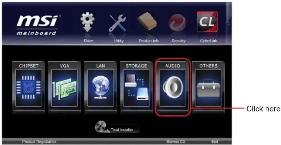
- Insert the application DVD into the DVD-ROM drive. The setup screen will automatically appear.
- Click Driver tab.
- Click AUDIO button.
text_image
msi™ mainboard Driver Utility Product info Security CyberLink CHIPSET VGA LAN STORAGE AUDIO OTHERS Total installer Click here Product Registration Browse CD Exit- Select Realtek HD Audio Drivers to start installing the drivers.
- Click Next to install the Realtek High Definition Audio Driver.
- Follow the on-screen instructions to install drivers.
- Click Finish to restart the system.

Important
The HD Audio Configuration software utility is under continuous update to enhance audio applications. Hence, the program screens shown here in this section may be slightly different from the latest software utility and shall be held for reference only.
Software Configuration
After installing the audio driver, the "Realtek HD Audio Manager" icon will appear at the notification area (lower right of the screen). You may double click the icon and the GUI will pop up accordingly.

text_image
double click the icon Customize...It is also available to enable the audio driver by clicking the Realtek HD Audio Manager from the Control Panel.
Software panel overview
The following figure describes the function of the Realtek HD Audio Manager panel.
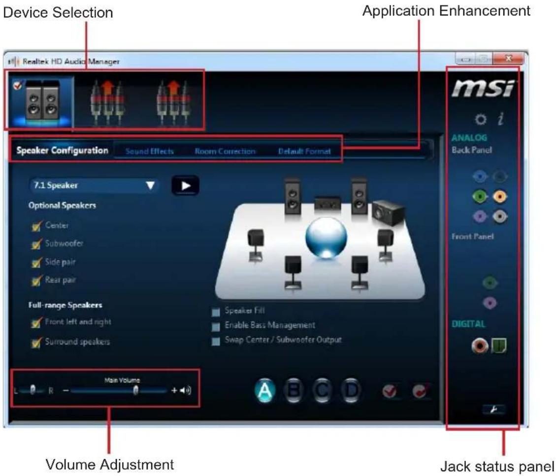
text_image
Device Selection Realtek HD Audio Manager Application Enhancement Speaker Configuration Sound Effects Room Correction Default Format 7.1 Speaker Optional Speakers Center Subwoofer Side pair Rear pair Full-range Speakers Front left and right Surround speakers Speaker Fill Enable Bass Management Swap Center / Subwoofer Output Main Volume Volume Adjustment Jack status panel■ Device Selection
Here you can select a audio output source to change the related options. The "check" sign (in orange) indicates the devices as default.
■ Volume Adjustment
You can control the volume or balance the right/left side of the speakers that you plugged in front or rear panel by adjust the bar.
■ Application Enhancement
The array of options will provide you a complete guidance of anticipated sound effect for both output and input device.
■ Jack status panel
This panel depicts all render and capture devices currently connected with your computer.
Auto popup dialog
When you plug into the device at the jack, a dialogue window will pop up asking you which device is current connected.
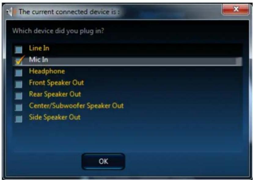
text_image
The current connected device is : Which device did you plug in? Line In ✓ Mic In Headphone Front Speaker Out Rear Speaker Out Center/Subwoofer Speaker Out Side Speaker Out OKAs you know, each jack corresponds to its default setting, you can refer to the next section "Hardware Default Setting".
Hardware Default Setting
The following diagrams are audio back panel default setting.
■ Backpanel audio jacks to 2-channel speakers diagram
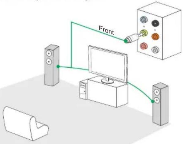
text_image
Front■ Backpanel audio jacks to 4-channel speakers diagram
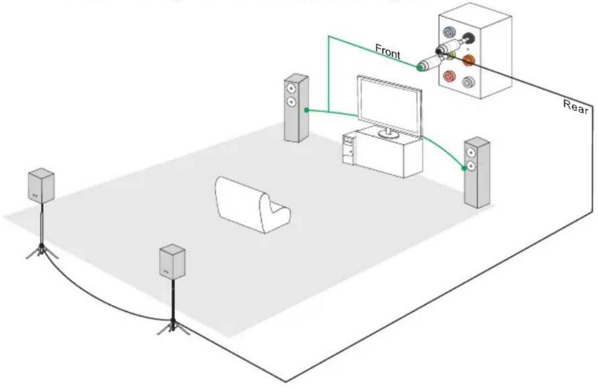
text_image
Front Rear■ Backpanel audio jacks to 6-channel speakers diagram
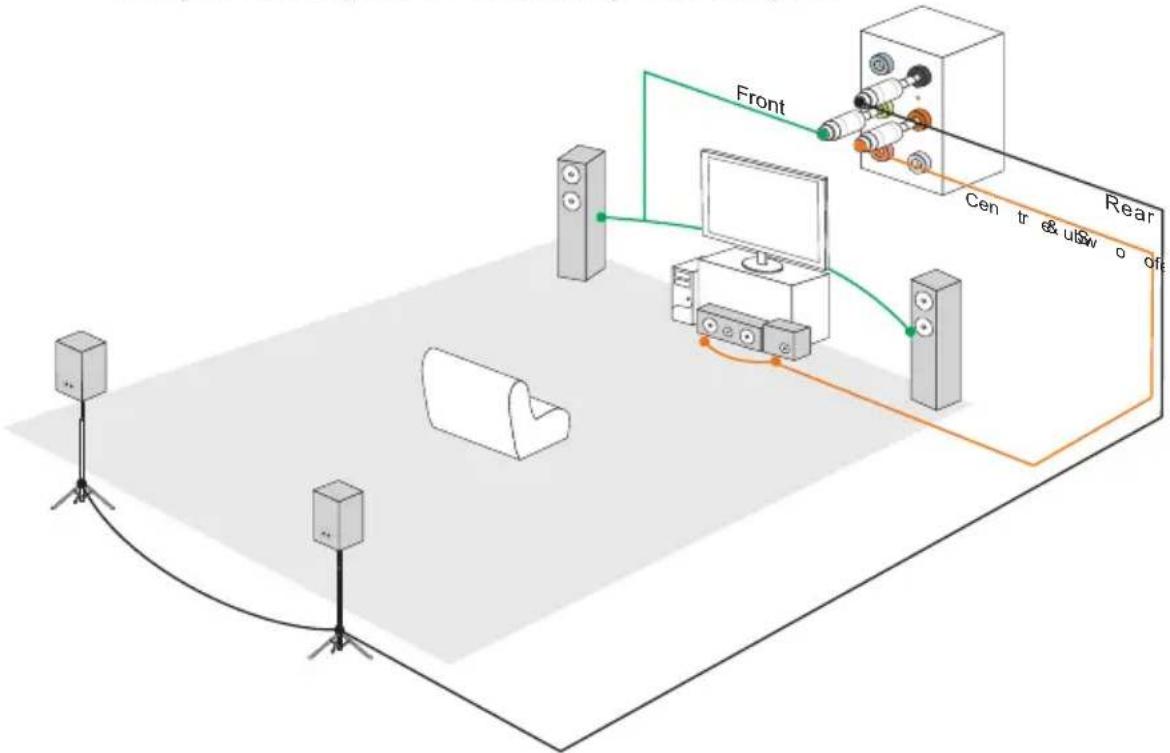
flowchart
graph TD
    A["Speaker"] --> B["Central Display"]
    C["Speaker"] --> B
    D["Speaker"] --> B
    B --> E["Rear"]
    style A fill:#f9f,stroke:#333
    style C fill:#f9f,stroke:#333
    style D fill:#f9f,stroke:#333
    style E fill:#ccf,stroke:#333
■ Backpanel audio jacks to 8-channel speakers diagram
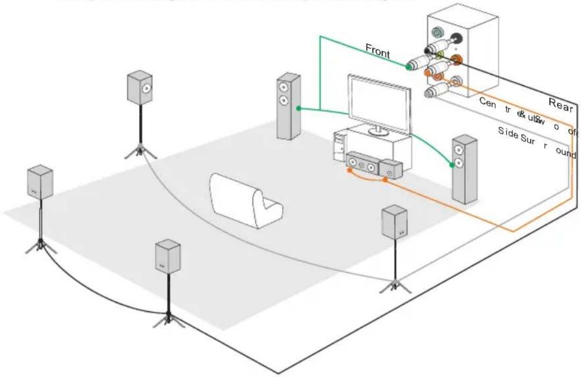
flowchart
graph TD
    A["Speaker"] --> B["Front"]
    B --> C["Central Monitor"]
    C --> D["Rear"]
    D --> E["Side Surround"]
    style A fill:#f9f,stroke:#333
    style B fill:#ccf,stroke:#333
    style C fill:#cfc,stroke:#333
    style D fill:#fcc,stroke:#333
    style E fill:#ffc,stroke:#333

natural_image
Abstract illustration of a globe with orbiting lines and data streams, no text or symbols presentAppendix B
Intel SBA
Intel® Small Business Advantage (Intel ® SBA) provides an out-of-the-box hardware-based security and productivity suite designed for the small business user. Intel SBA includes a customizable user interface and several bundled Intel applications.
Prerequisites
■ Supported Operating Systems
Intel SBA supports following OS:
■ Windows 7 Professional 64-bit and 32-bit
■ Windows 7 Enterprise 64-bit
■ Required User Permissions
You must run the installer and the customization wizard with a user that has local administrator permissions on the computer.
■ Windows Update Settings
In certain conditions, the Windows Update task in the PC Health Center application is disabled and cannot be enabled. This can occur if Intel SBA is installed on a computer where Windows Update was disabled during installation of the Windows operating system. The Windows Update task is shown in the GUI but is grayed out (disabled). Even if the end user enables Windows Update in the operating system, the PC Health Center task cannot be enabled. This means that the end user cannot use PC Health Center to manage Windows Update.
To prevent this, make sure that you do NOT select the Never check for updates option when installing the Windows operating system.
■ Windows Task Scheduler
Some PC Health Center tasks are applications that can also be used directly from the operating system and scheduled via the Windows Task Scheduler. When a task is set via PC Health Center, an alarm clock is set that will wake up the computer if it is turned off. Defining a scheduled time for an application/task outside of PC Health Center does not set an alarm clock. This means that the computer will not be woken up to do the task.
For this reason, it is NOT recommended to define schedules for these applications:
■ Windows Updates
■ Windows Backup and Restore
■ Disk defragmentation
Instead, let the end user set the schedule for all these tasks via PC Health Center.
Installing Intel SBA
This procedure describes how to install Intel SBA.
■ To install Intel SBA:
- Logon to the computer with a user that has administrator privileges.
- Insert the application DVD into the DVD-ROM drive. The setup screen will automatically appear.
- Click OTHERS tab.
- Select Intel SBA to start installing.
- Follow the on-screen instructions to install.
Software Configuration
After installation of the Intel SBA software is complete, the Intel SBA service is started. The desktop, system tray, and programs menu include shortcuts to the GUI of Intel SBA.
Software panel overview
The following figure describes the function of the Intel SBA control panel.
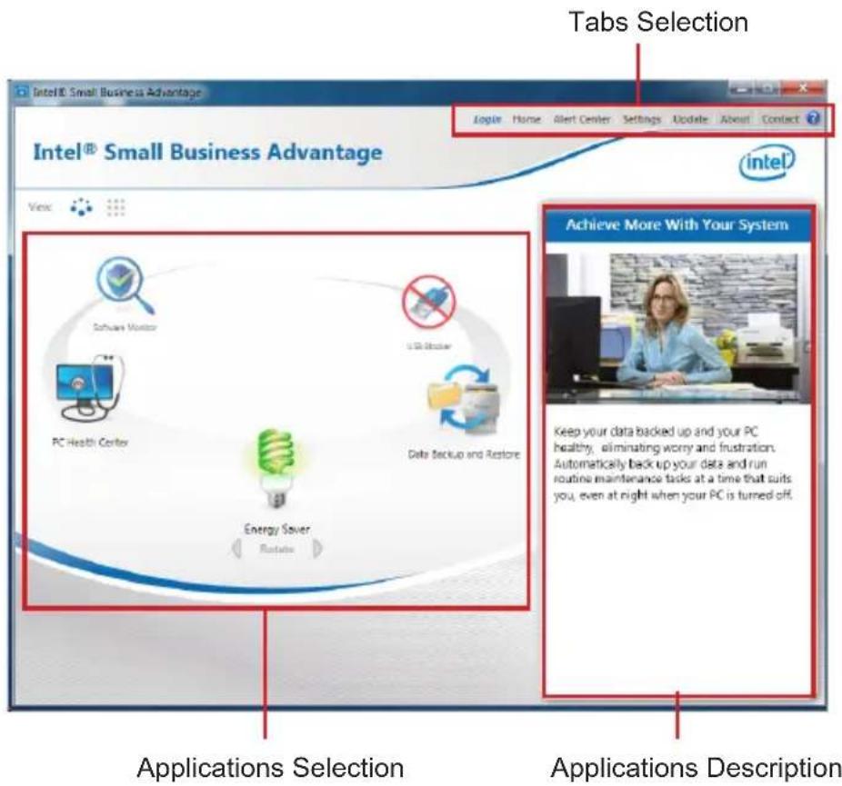
text_image
Intel® Small Business Advantage Tabs Selection Google Home Alert Center Settings Update About Contact Intel® Small Business Advantage View Achieve More With Your System Software Monitor USB Monitor PC Health Center Data Backup and Restore Energy Saver Rotate Keep your data backed up and your PC healthy, eliminating worry and frustration. Automatically back up your data and run routine maintenance tasks at a time that suits you, even at night when your PC is turned off. Applications Selection Applications DescriptionPassword settings
By default, the system is in an unconfigured state. Before the hardware capabilities can be used by Intel SBA software, the system must be configured. This is done in the Settings > Password Settings tab in the main menu of the GUI.
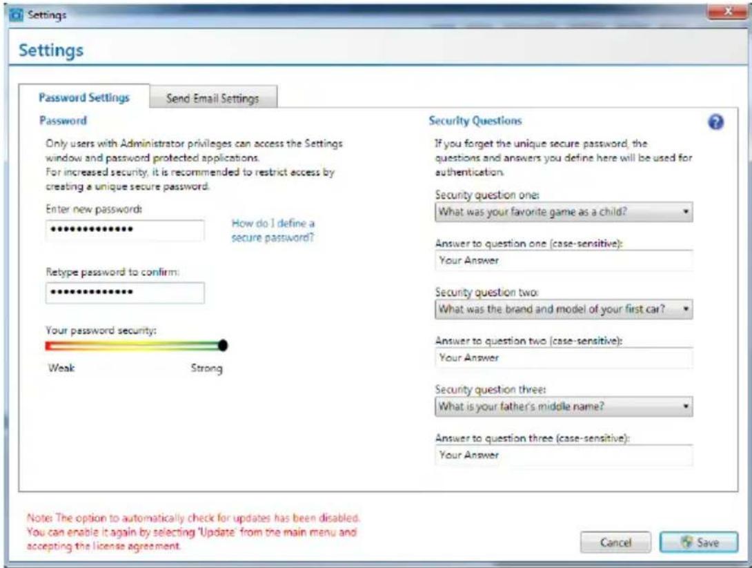
text_image
Settings Password Settings Send Email Settings Password Only users with Administrator privileges can access the Settings window and password protected applications. For increased security, it is recommended to restrict access by creating a unique secure password. Enter new passwords: How do I define a secure password? Reype password to confirm: Your password security: Weak Strong Security Questions If you forget the unique secure password, the questions and answers you define here will be used for authentication. Security question one: What was your favorite game as a child? Answer to question one (case-sensitive): Your Answer Security question two: What was the brand and model of your first car? Answer to question two (case-sensitive): Your Answer Security question three: What is your father's middle name? Answer to question three (case-sensitive): Your Answer Note: The option to automatically check for updates has been disabled. You can enable it again by selecting 'Update' from the main menu and accepting the license agreement. Cancel SaveFill out the form to create the new password and click "Save". You will be asked to enter the password when you want to start using Intel SBA.

Important
- Upon completion of the password settings, please keep your password secure.
- Please remember your answers to the security questions.
Help Button
There is a help button on the top right. If you need to know detailed introductions. Just click on the help button, to get the information.

natural_image
Abstract illustration of a globe with orbiting lines and floating elements (no text or symbols)Appendix C
Install Windows XP Notes
This chapter describes how to install Windows XP with IDE or AHCI mode.
Installing Windows XP with IDE Mode
You will fail and encounter a blue screen while installing Windows XP, because it is not natively supported to be installed in the storage device with AHCI mode. If you still prefer to install Windows XP as the operating system, please change the BIOS item as below.
- Refer to Chapter 2 to access BIOS.
- Go to SETTINGS → Integrated Peripherals → SATA Mode.
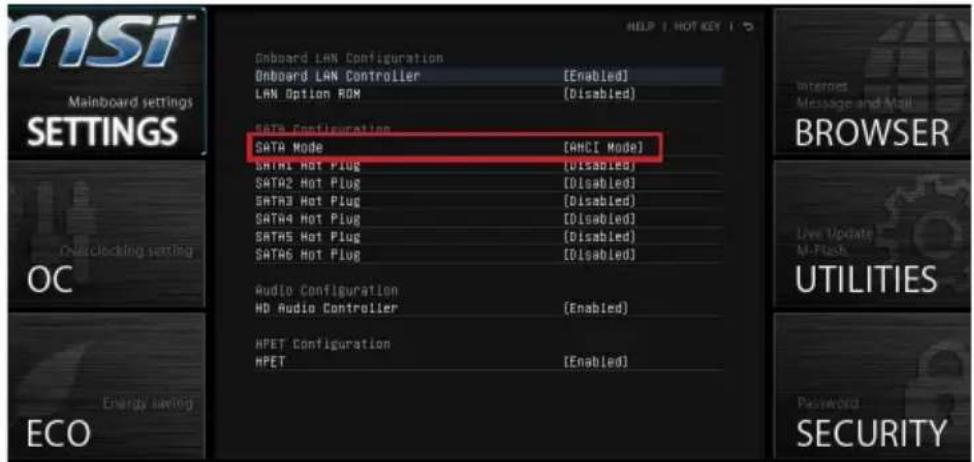
text_image
msi Mainboard settings SETTINGS OC Energy saving ECO Onboard LAN Configuration Onboard LAN Controller [Enabled] LAN Option ROM [Disabled] SATA Configuration SATA Mode [AHCI Mode] SATA1 Hot Plug [Disabled] SATA2 Hot Plug [Disabled] SATA3 Hot Plug [Disabled] SATA4 Hot Plug [Disabled] SATA5 Hot Plug [Disabled] SATA6 Hot Plug [Disabled] Audio Configuration HD Audio Controller [Enabled] HPET Configuration HPET [Enabled] HELP 1 HOT KEY 1 Internet Message and Mail BROWSER Live Update AI-Flash UTILITIES Password SECURITY- Set this item to IDE mode.
- Go to SETTINGS → Save & Exit → Save changes and reboot.
- Install the Windows XP operating system.
Installing Windows XP with AHCI Mode
If you prefer to install Windows XP as the operating system with AHCI mode, please prepare AHCI drivers for Windows XP in advanced.
Creating a Intel AHCI Driver Disc
Please follow the instruction below to make an "Intel® AHCI Driver" for yourself.
■ Insert the MSI DVD into the DVD-ROM drive.
- Click the "Browse CD" on the Setup screen.
- Copy all the contents from \Storage\Intel\PCH 7\f6flpy-x86 or f6flpy-x64 to a formatted floppy diskette.
■ The driver diskette is done.

Important
You can download the driver from
http://download3.msi.com/files/downloads/dvr_exe/intel7x_rst_floppy_mb.zip
Installing the Windows XP Operating System:
Please follow the below steps:
- Access BIOS, set SATA Mode to AHCI mode, save, exit and reboot.
- Ensure the USB Floppy Disk Drive is connected to the computer.
- Install Windows XP. When Windows Setup screen appears a message "Press F6 if you need to install a third party SCSI or RAID driver....", press "F6" key.
- Insert the floppy disk containing the AHCI drivers into the floppy disk drive.
- When the next screen appears, press the "S" key to specify an additional device.
- From the provided list, select the Intel(R) 7 Series SATA AHCI Controller.
- Follow the on-screen instructions to complete the installation.