760GM-E51 FX - Motherboard MSI - Free user manual and instructions
Find the device manual for free 760GM-E51 FX MSI in PDF.

User questions about 760GM-E51 FX MSI
0 question about this device. Answer the ones you know or ask your own.
Ask a new question about this device
Download the instructions for your Motherboard in PDF format for free! Find your manual 760GM-E51 FX - MSI and take your electronic device back in hand. On this page are published all the documents necessary for the use of your device. 760GM-E51 FX by MSI.
USER MANUAL 760GM-E51 FX MSI
series MS-7596 (v1.x) Mainboard
msi
Preface
Copyright Notice
The material in this document is the intellectual property of MICRO-STAR-STAR INTERNATIONAL. We take every care in the preparation of this document, but no guarantee is given as to the correctness of its contents. Our products are under continual improvement and we reserve the right to make changes without notice.
Trademarks
All trademarks in this manual are properties of their respective owners.
■ MSI® is registered trademark of Micro-Star Int'l Co., Ltd.
■ NVIDIA® is registered trademark of NVIDIA Corporation.
■ ATI ^® is registered trademark of AMD Corporation.
■ AMD® is registered trademarks of AMD Corporation.
Intel® is registered trademarks of Intel Corporation.
■ Windows® is registered trademarks of Microsoft Corporation.
■ AMI® is registered trademark of American Megatrends Inc.
■ Award® is a registered trademark of Phoenix Technologies Ltd.
■ Sound Blaster® is registered trademark of Creative Technology Ltd.
■ Realtek® is registered trademark of Realtek Semiconductor Corporation.
■ JMicron® is registered trademark of JMicron Technology Corporation.
■ Netware® is a registered trademark of Novell, Inc.
Lucid® is trademarks of LucidLogix Technologies, Ltd.
■ VIA® is registered trademark of VIA Technologies, Inc.
■ ASMedia® is registered trademark of ASMedia Technology Inc.
■ iPad, iPhone, and iPod are trademarks of Apple Inc.
Revision History
| Revision | Revision History Date | Date |
| V1.6 For AM3+ CPU 2011/05 | ||
Technical Support
If a problem arises with your system and no solution can be obtained from the user's manual, please contact your place of purchase or local distributor. Alternatively, please try the following help resources for further guidance.
Visit the MSI website for technical guide, BIOS updates, driver updates, and other information: http://www.msi.com/service/download
Contact our technical staff at: http://support.msi.com
Safety Instructions
■ Always read the safety instructions carefully.
- Keep this User's Manual for future reference.
- Keep this equipment away from humidity.
■ Lay this equipment on a reliable flat surface before setting it up.
■ The openings on the enclosure are for air convection hence protects the equipment from overheating. DO NOT COVER THE OPENINGS.
■ Make sure the voltage of the power source is at 110/220V before connecting the equipment to the power inlet.
■ Place the power cord such a way that people can not step on it. Do not place anything over the power cord.
■ Always Unplug the Power Cord before inserting any add-on card or module.
■ All cautions and warnings on the equipment should be noted.
■ Never pour any liquid into the opening that can cause damage or cause electrical shock.
■ If any of the following situations arises, get the equipment checked by service personnel:
○ The power cord or plug is damaged.
○ Liquid has penetrated into the equipment.
○ The equipment has been exposed to moisture.
The equipment does not work well or you can not get it work according to User's Manual.
○ The equipment has been dropped and damaged.
○ The equipment has obvious sign of breakage.
DO NOT LEAVE THIS EQUIPMENT IN AN ENVIRONMENT ABOVE 60°C (140°F), IT MAY DAMAGE THE EQUIPMENT.
CAUTION: There is a risk of explosion, if battery is incorrectly replaced.
Replace only with the same or equivalent type recommended by the manufacturer.
警告使用者:
For better environmental protection, waste batteries should be collected separately for recycling special disposal.
FCC-B Radio Frequency Interference Statement
This equipment has been tested and found to comply with the limits for a Class B digital device, pursuant to Part 15 of the FCC Rules. These limits are designed to provide reasonable protection against harmful inter-

text_image
CEN1996
ference in a residential installation. This equipment generates, uses and can radiate radio frequency energy and, if not installed and used in accordance with the instructions, may cause harmful interference to radio communications. However, there is no guarantee that interference will not occur in a particular installation. If this equipment does cause harmful interference to radio or television reception, which can be determined by turning the equipment off and on, the user is encouraged to try to correct the interference by one or more of the measures listed below.
○ Reorient or relocate the receiving antenna.
○ Increase the separation between the equipment and receiver.
○ Connect the equipment into an outlet on a circuit different from that to which the receiver is connected.
Consult the dealer or an experienced radio/television technician for help.
Notice 1
The changes or modifications not expressly approved by the party responsible for compliance could void the user's authority to operate the equipment.
Notice 2
Shielded interface cables and A.C. power cord, if any, must be used in order to comply with the emission limits.
VOIR LA NOTICE D'INSTALLATION AVANT DE RACCORDER AU RESEAU.

text_image
Micro-Star International MS-7596This device complies with Part 15 of the FCC Rules. Operation is subject to the following two conditions:
1) this device may not cause harmful interference, and
2) this device must accept any interference received, including interference that may cause undesired operation.
WEEE (Waste Electrical and Electronic Equipment) Statement
ENGLISH
To protect the global environment and as an environmentalist, MSI must remind you that...

Under the European Union ("EU") Directive on Waste Electrical and Electronic Equipment, Directive 2002/96/EC, which takes effect on August 13, 2005 products of "electrical and electronic equipment" cannot be discarded as municipal wastes anymore, and manufacturers of covered electronic equipment will be obligated to take back such products at the end of their useful life. MSI will comply with the product take back requirements at the end of life of MSI-branded products that are sold into the EU. You can return these products to local collection points.
DEUTSCH
Technical Support....ii
Safety Instructions
FCC-B Radio Frequency Interference Statement...... iv
WEEE (Waste Electrical and Electronic Equipment) Statement ...... v
Chapter 1 Getting Started....1-1
Mainboard Specifications 1-2
Mainboard Layout 1-4
Packing Checklist 1-5
Chapter 2 Hardware Setup 2-1
Quick Components Guide 2-2
CPU (Central Processing Unit) 2-3
Memory 2-6
Power Supply 2-8
Back Panel 2-9
Connectors 2-11
Jumper 2-18
Switch 2-19
Slots 2-20
LED Status Indicators 2-23
Chapter 3 BIOS Setup 3-1
Entering Setup 3-2
The Main Menu 3-4
Standard CMOS Features 3-6
Advanced BIOS Features 3-9
Integrated Peripherals 3-12
Power Management Setup 3-14
H/W Monitor 3-16
Green Power 3-17
BIOS Setting Password 3-18
Cell Menu 3-19
M-Flash 3-24
User Settings 3-27
Load Fail-Safe/ Optimized Defaults ....3-28
Appendix A Realtek Audio A-1
Installing the Realtek HD Audio Driver ....A-2
Software Configuration ......A-4
Hardware Setup ....A-19
Appendix B SB710 RAID B-1
RAID Configuration ......B-2
Appendix C Overclocking Center ...... C-1
Activating Overclocking Center C-2
System Info C-3
DOT C-5
Chapter 1 Getting Started
Thank you for choosing the 785GM-E51 (FX)/ 760GM-E51 (FX) Series (MS-7596 v1.X) Micro ATX mainboard. The 785GM-E51 (FX)/ 760GM-E51 (FX) Series mainboards are based on AMD® 785G/ 760G & SB710 chipsets for optimal system efficiency. Designed to fit the advanced AMD® processors in AM3+ package, the 785GM-E51 (FX)/ 760GM-E51 (FX) Series deliver a high performance and professional desktop platform solution.
MAINBOARD SPECIFICATIONS
Processor Support
■ AMD® 64 bits Phenom™ II processor in AM3+ package. (For the latest information about CPU, please visit http://www.msi.com/service/cpu-support)
HyperTransport
■ HyperTransport™ 3.0, supports up to 2.6 GHz
Chipset
- North Bridge: AMD®785G/ 760G chipset - South Bridge: AMD® SB710 chipset
Integrated Graphic
- Integrated ATI Radeon™ HD4200 GPU (for AMD® 785G chipset) - Integrated ATI Radeon™ HD3000 GPU (for AMD® 760G chipset) - Share Memory: Max up to 512MB
Memory Support
- DDR3 1333/ 1066/ 800 SDRAM (total 16 GB Max) - 4 DDR3 DIMMs (240-pin/ 1.5V) (For more information on compatible components, please visit http://www.msi.com/service/test-report)
LAN
■ Supports PCIE LAN 10/100/1000 Fast Ethernet by Realtek® RTL8111DL
Audio
- Chip integrated by Realtek® ALC888S/ ALC889 - Flexible 8-channel audio with jack sensing - Compliant with Azalia 1.0 Spec
IDE
■ 1 IDE port by AMD ^® SB710 ■ Supports Ultra DMA 66/100/133 mode ■ Supports PIO, Bus Master operation mode
SATA
- 5 SATAII ports by AMD® SB710 - 1 eSATA port by AMD®SB710 - Supports storage and data transfers at up to 3 Gb/s
RAID
■ SATA1\~5 supports RAID 0/1/0+1 or JBOD mode by AMD® SB710
Floppy
■ 1 floppy port
■ Supports 1 FDD with 360 KB, 720 KB, 1.2 MB, 1.44 MB and 2.88 MB
Connectors
■ Back panel
- 1 PS/2 keyboard or mouse port
- 1 VGA port
- 1 DVI-D port
- 6 USB 2.0 ports
- 1 HDMI port
- 1 eSATA port
- 1 LAN port
- 6 flexible audio ports
■ On-Board
- 3 USB 2.0 connectors
- 1 Chassis Intrusion connector
- 1 Serial port connector
- 1 Parallel port connector
- 1 CD-In connector
- 1 Front Panel Audio connector
- 1 SPDIF-out connector
- 1 TPM Module connector
- 1 Overclock FSB switch
Slots
■ 1 PCI Express Gen2 x16 slot
■ 1 PCI Express x1 slot
■ 2 PCI slots, support 3.3V/5V PCI bus Interface
Form Factor
■ Micro-ATX (24.4 cm X 24.4 cm)
Mounting
■ 8 mounting holes
If you need to purchase accessories and request the part numbers, you could search the product web page and find details on our web address below http://www.msi.com/index.php
MAINBOARD LAYOUT
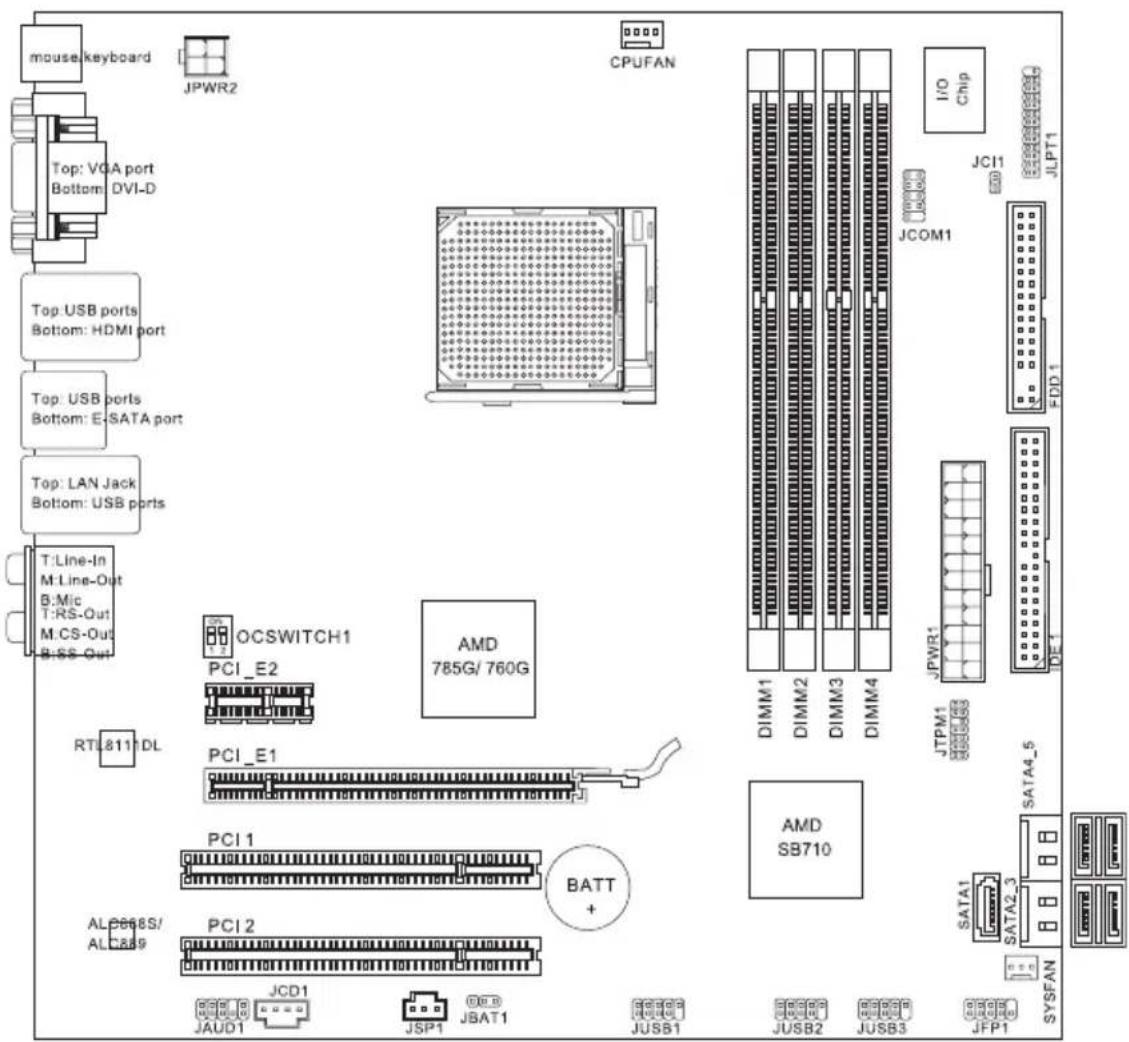
text_image
mouse keyboard Top: VGA port Bottom: DVI-D Top: USB ports Bottom: HDMI port Top: USB ports Bottom: E:SATA port Top: LAN Jack Bottom: USB ports T:Line-In M:Line-Out B:Mic T:RS-Out M:CS-Out B:SS-Out RTL811 DL OCSWITCH1 PCI_E2 PCI_E1 PCI 1 BATT + ALC668S/ ALC889 PCI 2 JCD1 JAUD1 JSP1 JBAT1 CPUFAN AMD 785G/760G I/O Chip JCOM1 JCP11 JLPT1 FDD 1 DIMM1 DIMM2 DIMM3 DIMM4 JTPM1 SB710 JSPWR1 SATA4_5 SATA2_3 JFP1 JUSB2 JUSB3785GM-E51 (FX)/ 760GM-E51 (FX) Series
(MS-7596 v1.X) Mainboard
PACKING CHECKLIST
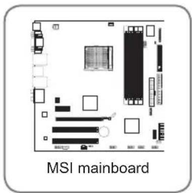
text_image
MSI mainboard
text_image
MSI Driver/Utility DVD
natural_image
Red cable with black connectors, labeled 'SATA Cable (Optional)' below (no other text or symbols)
natural_image
Close-up of a black and white power cable connector with three red wires (no text or symbols on the device body)
natural_image
USB connector with cable and connector (no text or symbols on the device itself)
text_image
Standard Cable for IDE Devices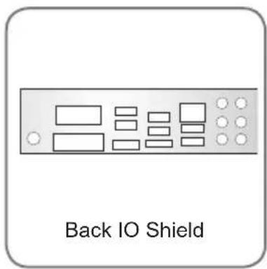
text_image
Back IO Shield
text_image
MANUAL User's Guide* The pictures are for reference only and may vary from the packing contents of the product you purchased. If you need to purchase accessories and request the part numbers, you could search the product web page and find details on our web address http://www.msi.com/index.php
Chapter 2 Hardware Setup
This chapter provides you with the information about hardware setup procedures. While doing the installation, be careful in holding the components and follow the installation procedures. For some components, if you install in the wrong orientation, the components will not work properly.
Use a grounded wrist strap before handling computer components. Static electricity may damage the components.
QUICK COMPONENTS GUIDE
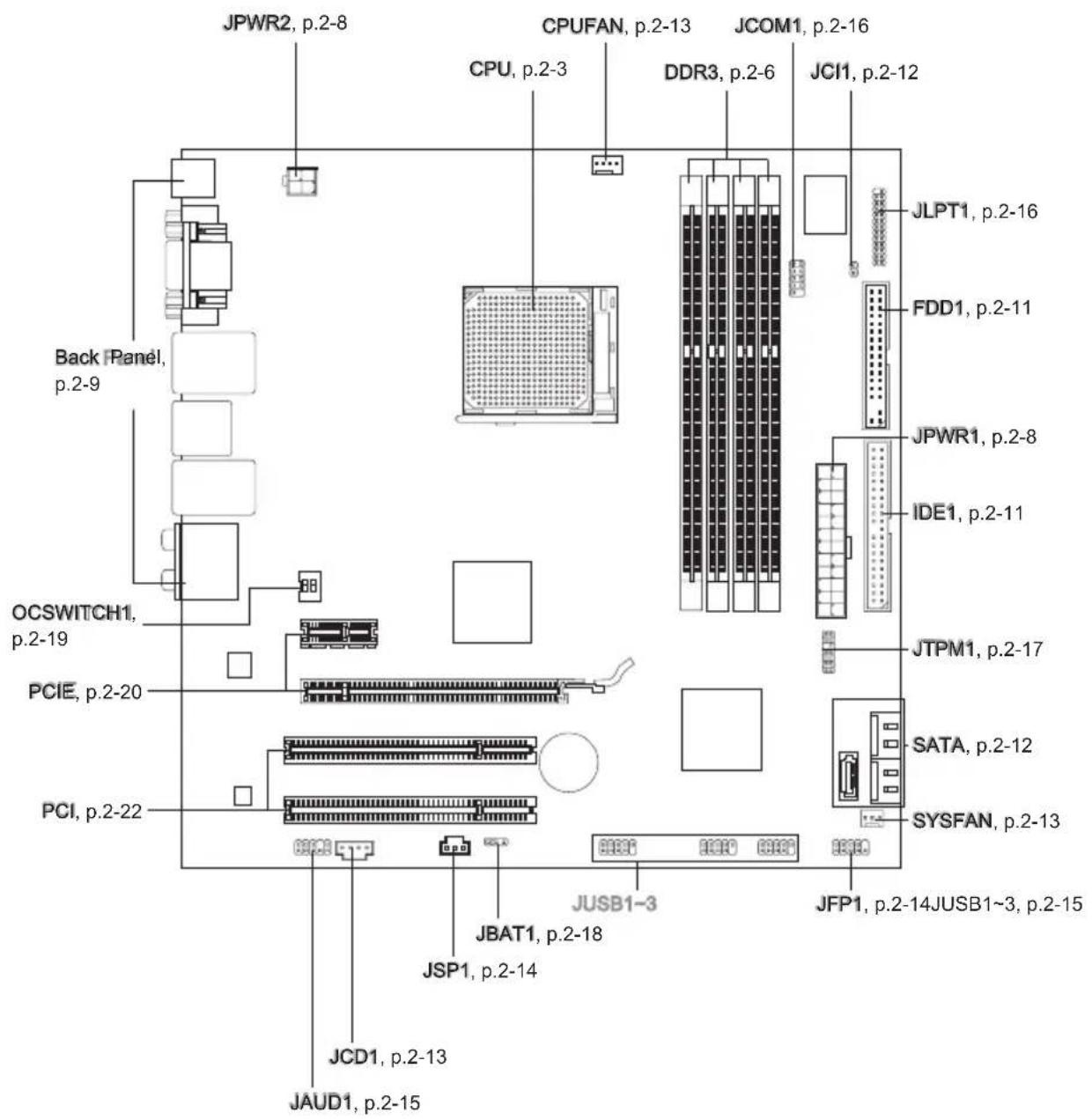
text_image
JPWR2, p.2-8 CPU, p.2-3 JCOM1, p.2-16 JCI1, p.2-12 Back Panel, p.2-9 OCSWITCH1, p.2-19 PCIE, p.2-20 PCI, p.2-22 JBAT1, p.2-18 JSP1, p.2-14 JCD1, p.2-13 JAUD1, p.2-15 JUSB1-3 JFP1, p.2-14JUSB1~3, p.2-15 JTPM1, p.2-17 IDE1, p.2-11 JPWR1, p.2-8 FDD1, p.2-11 JLPT1, p.2-16CPU (CENTRAL PROCESSING UNIT)
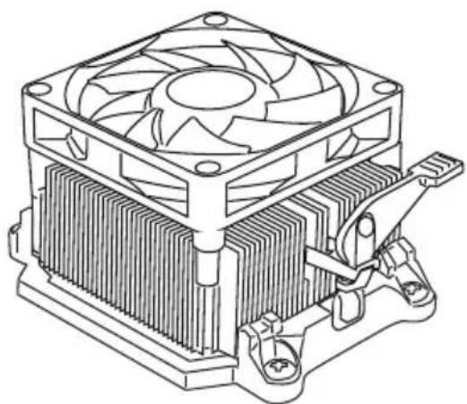
When you are installing the CPU, make sure to install the cooler to prevent overheating. If you do not have the CPU cooler, consult your dealer before turning on the computer.
For the latest information about CPU, please visit
http://www.msi.com/service/cpu-support
Important
Overheating
Overheating will seriously damage the CPU and system. Always make sure the cooling fan can work properly to protect the CPU from overheating. Make sure that you apply an even layer of thermal paste (or thermal tape) between the CPU and the heatsink to enhance heat dissipation.
Replacing the CPU
While replacing the CPU, always turn off the ATX power supply or unplug the power supply's power cord from the grounded outlet first to ensure the safety of CPU.
Overclocking
This mainboard is designed to support overclocking. However, please make sure your components are able to tolerate such abnormal setting, while doing overclocking. Any attempt to operate beyond product specifications is not recommended. We do not guarantee the damages or risks caused by inadequate operation or beyond product specifications.
Introduction to AM3+ CPU
The surface of CPU. Remember to apply some thermal paste on it for better heat dispersion.

natural_image
Plain gray square with black border and a small red circle highlighting the corner (no text or symbols)Gold arrow
CPU & Cooler Installation
When you are installing the CPU, make sure the CPU has a cooler attached on the top to prevent overheating. Meanwhile, do not forget to apply some thermal paste on CPU before installing the heat sink/cooler fan for better heat dispersion.
Follow the steps below to install the CPU & cooler correctly. Wrong installation will cause the damage of your CPU & mainboard.
-
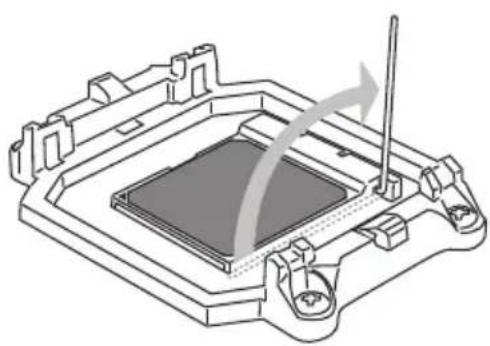
Pull the lever sideways away from the socket. Make sure to raise the lever up to a 90-degree angle.
-
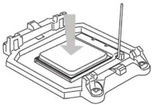
Look for the gold arrow of the CPU. The gold arrow should point as shown in the picture. The CPU can only fit in the correct orientation.
natural_image
Technical line drawing of a mechanical component with no visible text or symbols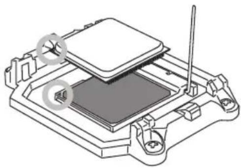
natural_image
Technical line drawing of a mechanical assembly with no visible text or symbols-
Preset GCPU directly installed, the pins should be completely embedded into the socket and can not be seen. Please note that any violation of the correct installation procedures may cause permanent damages to your mainboard.
-
socket and close the lever. As the CPU is likely to move while the lever is being closed, always close the lever with your fingers pressing tightly on top of the CPU to make sure the CPU is properly and completely embedded into the socket.
natural_image
Technical line drawing of a mechanical component with a downward arrow indicating a process or assembly (no text or symbols present)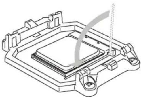
natural_image
Technical line drawing of a mechanical component with no visible text or symbols5. The species stole wood ringset and of the retention mechanism.
Hook one end of the clip to hook first.
6.
clip to fasten the cooling set on the top of the retention mechanism.
Locate the Fix Lever and lift up it.

natural_image
Technical line drawing of a computer CPU with cooling fan and heatsink (no text or symbols)
natural_image
Technical line drawing of a computer cooling fan with heatsink and cooling bracket (no text or symbols)Fasten down the lever.7. Attach the CPU 8 an cable to the CPU
fan connector on the mainboard.
natural_image
Technical line drawing of a computer cooling fan with heatsink and cooling bracket (no text or symbols)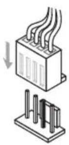
natural_image
Diagram showing two types of electrical connectors: a heat exchanger and a circuit board (no text or symbols)Important
While disconnecting the Safety Hook from the fixed bolt, it is necessary to keep an eye on your fingers, because once the Safety Hook is disconnected from the fixed bolt, the fixed lever will spring back instantly.
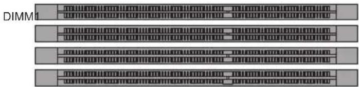
Memory
These DIMM slots are used for installing memory modules. For more information on compatible components, please visit http://www.msi.com/service/test-report
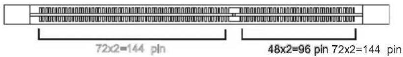
DDR3
240-pin, 1.5V
text_image
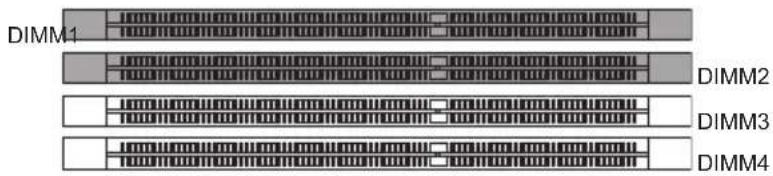
72x2=144 pin 48x2=96 pin 72x2=144 pinDual-Channel mode Population Rule
In Dual-Channel mode, the memory modules can transmit and receive data with two data bus lines simultaneously. Enabling Dual-Channel mode can enhance the system performance. The following illustrations explain the population rules for Dual-Channel mode.
①
text_image
DIMM1 DIMM2 DIMM3 DIMM4DIMM2
DIMM3
DIMM4
②
text_image
DIMM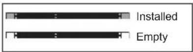
text_image
Installed EmptyImportant
- DDR3 memory modules are not interchangeable with DDR2 and the DDR3 standard is not backwards compatible. You should always install DDR3 memory modules in the DDR3 DIMM slots.
- In Dual-Channel mode, make sure that you install memory modules of the same type and density in different channel DIMM slots.
- To enable successful system boot-up, always insert the memory modules into the DIMM1 first.
- Due to the chipset resource deployment, the system density will only be detected up to 15+GB (not full 16GB) when each DIMM is installed with a 4GB memory module.
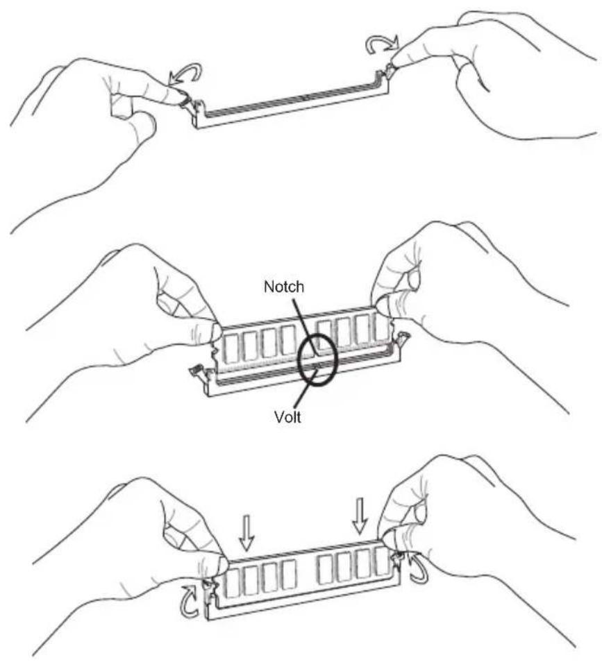
Installing Memory Modules
- The memory module has only one notch on the center and will only fit in the right orientation.
- Insert the memory module vertically into the DIMM slot. Then push it in until the golden finger on the memory module is deeply inserted in the DIMM slot. The plastic clip at each side of the DIMM slot will automatically close when the memory module is properly seated.
- Manually check if the memory module has been locked in place by the DIMM slot clips at the sides.
Important
You can barely see the golden finger if the memory module is properly inserted in the DIMM slot.
text_image
Notch VoltPOWER SUPPLY
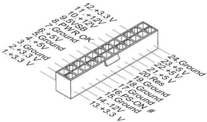
ATX 24-pin Power Connector: JPWR1
This connector allows you to connect an ATX 24-pin power supply. To connect the ATX 24-pin power supply, make sure the plug of the power supply is inserted in the proper orientation and the pins are aligned. Then push down the power supply firmly into the connector.
You may use the 20-pin ATX power supply as you like. If you'd like to use the 20-pin ATX power supply, please plug your power supply along with pin 1 & pin 13.
text_image
12 +3.3 V 11 +12 V 9.5 VSB 7. Ground 6. +5 V 4. +5 V 3. Ground 2. +3.3 V 1. +3.3 V 24 Ground 23 +5 V 22 +5 V 21 +5 V 20 Res 19 Ground 18 Ground 17 Ground 16 PS-ON # 15 Ground 14 -12 V 13 +3.3 VATX 4-pin Power Connector: JPWR2
This connector is used to provide power to the CPU.
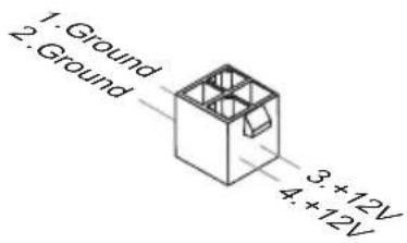
text_image
1. Ground 2. Ground 3. +12V 4. +12VImportant
• Make sure that all the connectors are connected to proper ATX power supplies to ensure stable operation of the mainboard.
Back Panel
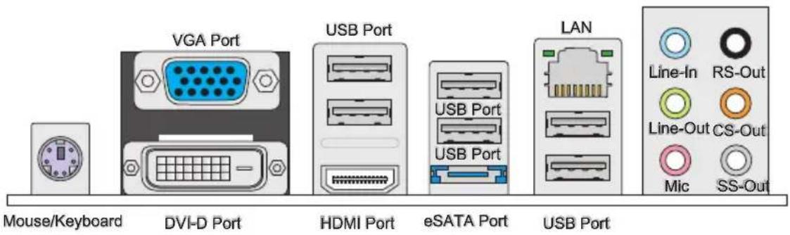
text_image
Mouse/Keyboard DVI-D Port VGA Port USB Port HDMI Port eSATA Port LAN USB Port Line-In RS-Out Line-Out CS-Out Mic SS-Out▶ Mouse/Keyboard
The standard PS/2 ^® mouse/keyboard DIN connector is for a PS/2 ^® mouse/keyboard.
▶ VGA Port
The DB15-pin female connector is provided for monitor.
▶ DVI-D Port
The DVI-D (Digital Visual Interface-Digital) connector allows you to connect a LCD monitor. It provides a high-speed digital interconnection between the computer and its display device. To connect an LCD monitor, simply plug your monitor cable into the DVI-D connector, and make sure that the other end of the cable is properly connected to your monitor (refer to your monitor manual for more information.)
▶ USB Port
The USB (Universal Serial Bus) port is for attaching USB devices such as keyboard, mouse, or other USB-compatible devices.
▶ HDMI Port
The High-Definition Multimedia Interface (HDMI) is an all-digital audio/video interface capable of transmitting uncompressed streams. HDMI supports all TV format, including standard, enhanced, or high-definition video, plus multi-channel digital audio on a single cable.
▶ eSATA Port
The eSATA (External-SATA) port is for attaching the eSATA hard drive.
▶ LAN
The standard RJ-45 LAN jack is for connection to the Local Area Network (LAN). You can connect a network cable to it.

| LED Color LED State Condition | Condition | ||
| Left Yellow Off LAN | N link is NOT established. | ||
| On(Steady state) LAN link is established. | |||
| On(brighter & pulsing) The computer is communicating with another computer on the LAN. | |||
| Right | Green Off 10 Mbits/sec data rate is selected. | ||
| Orange On 1000 Mbits/sec data rate is selected. | |||
▶ Audio Ports
These audio connectors are used for audio devices. It is easy to differentiate between audio effects according to the color of audio jacks.
■ Line-In (Blue) - Line In, is used for external CD player, tape-player or other audio devices.
■ Line-Out (Green) - Line Out, is a connector for speakers or headphones.
■ Mic (Pink) - Mic, is a connector for microphones.
■ RS-Out (Black) - Rear-Surround Out in 4/5.1/7.1 channel mode.
■ CS-Out (Orange) - Center/ Subwoofer Out in 5.1/7.1 channel mode.
■ SS-Out (Gray) - Side-Surround Out 7.1 channel mode.
CONNECTORS
Floppy Disk Drive Connector: FDD1
This connector supports 360 KB, 720 KB, 1.2 MB, 1.44 MB or 2.88 MB floppy disk drive.
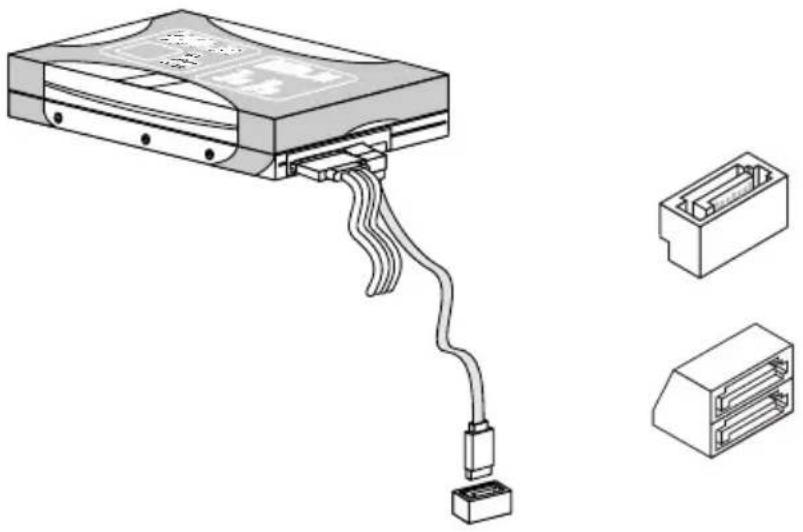
natural_image
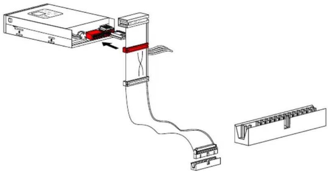
Diagram of a device assembly showing internal components and cable routing (no text or labels)IDE Connector: IDE1
This connector supports IDE hard disk drives, optical disk drives and other IDE devices.
natural_image
Technical line drawing of a computer drive system showing cable routing from an external CPU to a terminal block (no text or labels)Important
If you install two IDE devices on the same cable, you must configure the drives separately to master / slave mode by setting jumpers. Refer to IDE device's documentation supplied by the vendors for jumper setting instructions.
Hardware Setup
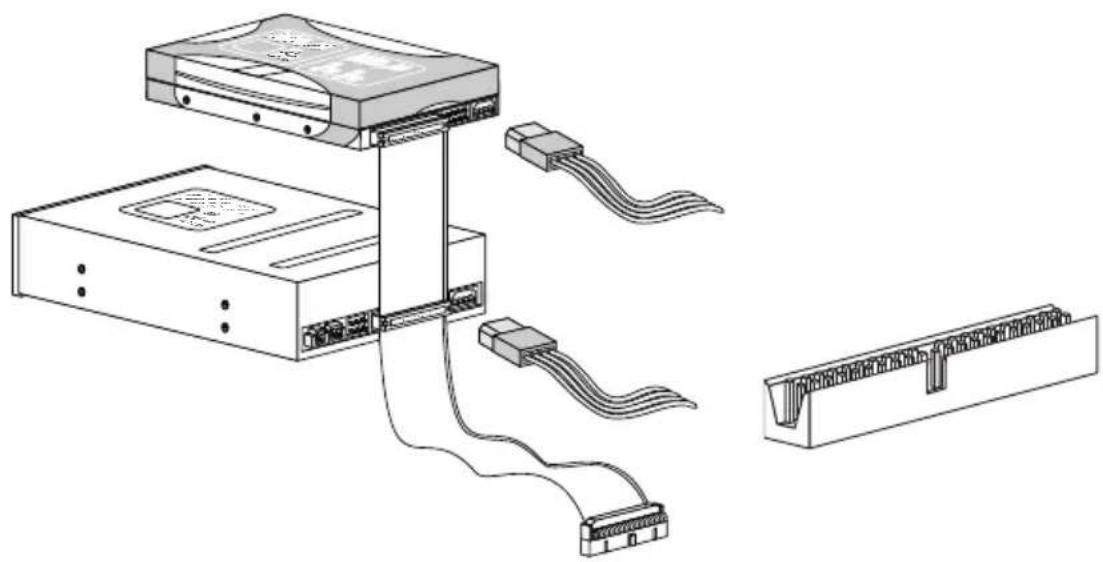
Serial ATA Connector: SATA1\~5
This connector is a high-speed Serial ATA interface port. Each connector can connect to one Serial ATA device.
natural_image
Technical line drawing of an electronic device with cable and connector, shown alongside two views (no text or symbols)Important
Please do not fold the Serial ATA cable into 90-degree angle. Otherwise, data loss may occur during transmission.
Chassis Intrusion Connector: JCI1
This connector connects to the chassis intrusion switch cable. If the chassis is opened, the chassis intrusion mechanism will be activated. The system will record this status and show a warning message on the screen. To clear the warning, you must enter the BIOS utility and clear the record.
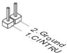
text_image
2. Ground 1. CINTRUFan Power Connectors: CPUFAN, SYSFAN
The fan power connectors support system cooling fan with +12V. When connecting the wire to the connectors, always note that the red wire is the positive and should be connected to the +12V; the black wire is Ground and should be connected to GND. If the mainboard has a System Hardware Monitor chipset on-board, you must use a specially designed fan with speed sensor to take advantage of the CPU fan control.

text_image
1: Ground 2: +12V 3: Sensor 4: Control CPUFAN SYSFAN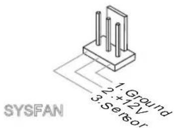
text_image
1: Ground 2: 12V 3: Sensor SYSFANImportant
- Please refer to the recommended CPU fans at processor's official website or consult the vendors for proper CPU cooling fan.
- CPUFAN supports fan control. You can install Overclocking Center utility that will automatically control the CPU fan speed according to the actual CPU temperature.
• Fan cooler set with 3 or 4 pins power connector are both available for CPUFAN.
CD-In Connector: JCD1
This connector is provided for external audio input.
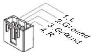
text_image
1: L 2: Ground 3: Ground 4: RHardware Setup
Front Panel Connector: JFP1
This connector is for electrical connection to the front panel switches and LEDs. The JFP1 is compliant with Intel® Front Panel I/O Connectivity Design Guide.
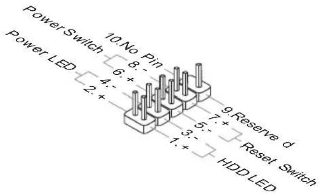
text_image
PowerSwitch 10. No Pin 8: + 6: + 4: + 2: + 9. Reserve d 7: + Reset Switch Power LED 3: + 1: + HDD LEDS/PDIF-Out Connector: JSP1
This connector is used to connect S/PDIF (Sony & Philips Digital Interconnect Format) interface for digital audio transmission.
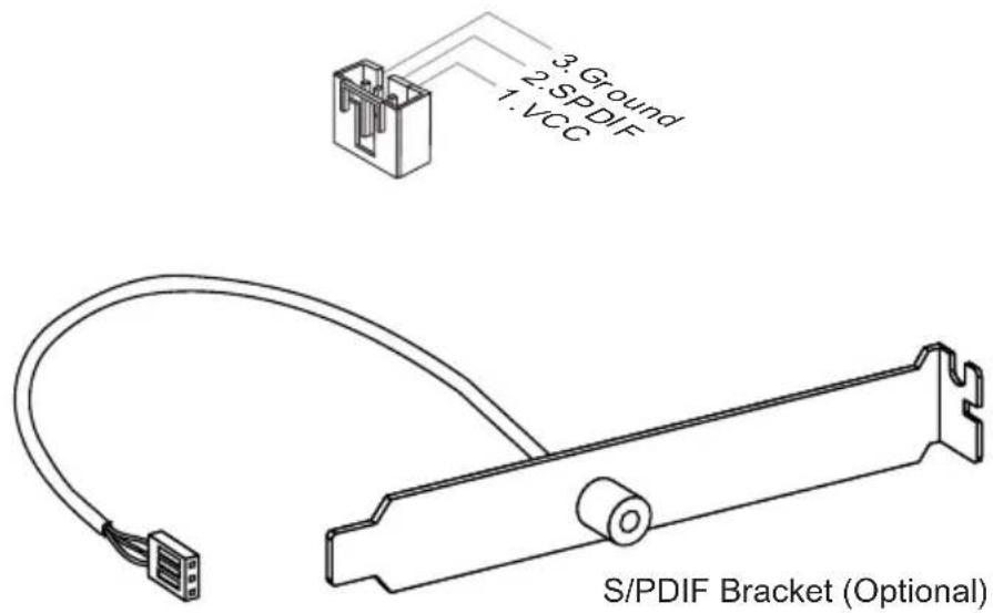
text_image
3. Ground 2. SPDF 1. VCC S/PDIF Bracket (Optional)Front USB Connector: JUSB1 / JUSB2 / JUSB3
This connector, compliant with Intel ^ I/O Connectivity Design Guide, is ideal for connecting high-speed USB interface peripherals such as USB HDD, digital cameras, MP3 players, printers, modems and the like.
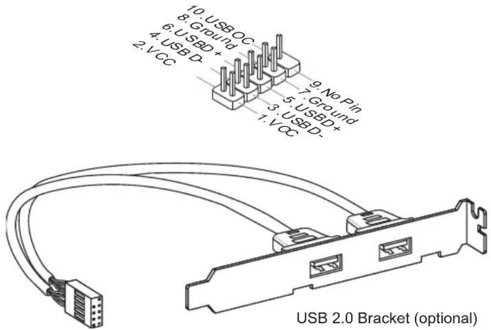
text_image
10. USB OC 8. Ground 6. USBD+ 4. USB D- 2. VCC 9. No Pin 7. Ground 5. USBD+ 3. USBD- 1. VCC USB 2.0 Bracket (optional)Important
Note that the pins of VCC and GND must be connected correctly to avoid possible damage.
Front Panel Audio Connector: JAUD1
This connector allows you to connect the front panel audio and is compliant with Intel® Front Panel I/O Connectivity Design Guide.
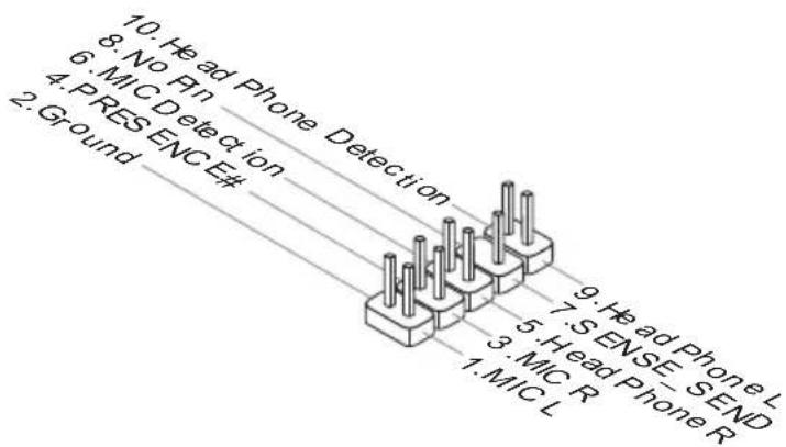
text_image
10. Head Phone Detection 8. No Pin 6. MIC Detection 4. PRESENCE# 2. Ground 9. Head Phone L 7. SENSE SEND 5. Head Phone R 3. MIC R 1. MIC LHardware Setup
Serial Port Connector: JCOM1
This connector is a 16550A high speed communication port that sends/ receives 16 bytes FIFOs. You can attach a serial device.

text_image
10.No Pin 8.CTS 6.DSR 4.DTR 2.SIN 9.RI 7.RTS 5.Ground 3.SOUT 1.DCDParallel Port Connector: JLPT1
This connector is used to connect an optional parallel port bracket. The parallel port is a standard printer port that supports Enhanced Parallel Port (EPP) and Extended Capabilities Parallel Port (ECP) mode.
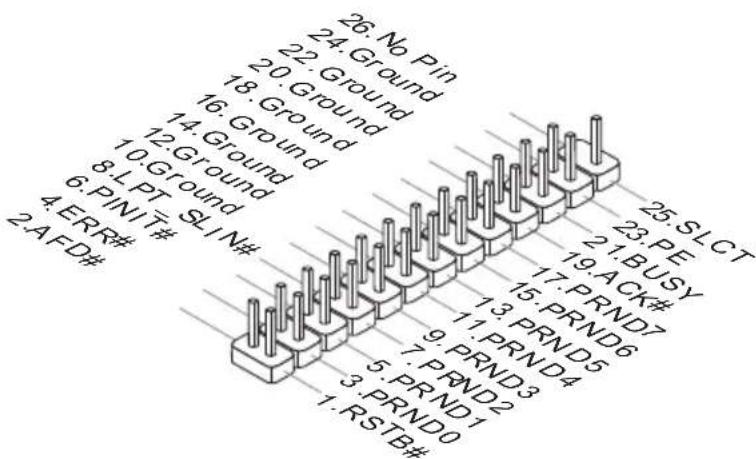
text_image
26. No Pin 24. Ground 22. Ground 18. Ground 16. Ground 14. Ground 12. Ground 8. LPT SIN# 4. ERR# 2. AFD# 25. SLCT 23. PE 19. BUSY 17. ACK# 15. PRND7 13. PRND6 11. PRND5 9. PRND3 7. PRND4 5. PRND2 3. PRND1 1. RSTB# 3. PRND0TPM Module connector: JTPM1
This connector connects to a TPM (Trusted Platform Module) module (optional). Please refer to the TPM security platform manual for more details and usages.
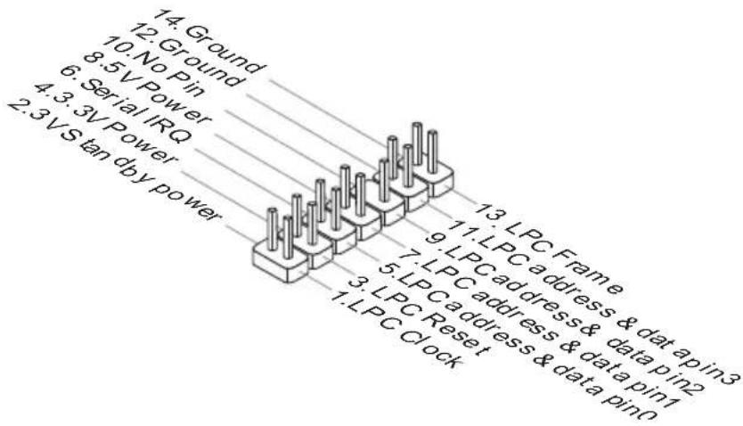
text_image
14. Ground 12. Ground 10. No Pin 8.5 V Power 6. Serial IRQ 4.3.3V Power 2.3 V S tan dby power 11. LPC Frame 9. LPC address & data pin2 7. LPC address & data pin1 5. LPC address & data pin0 3. LPC Reset 1. LPC Clock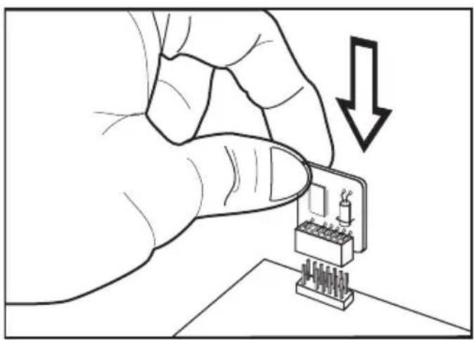
natural_image
Illustration of a hand inserting a component into a microchip with a downward arrow (no text or symbols)Hardware Setup
JUMPER
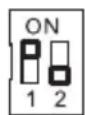
Clear CMOS Jumper: JBAT1
There is a CMOS RAM onboard that has a power supply from an external battery to keep the data of system configuration. With the CMOS RAM, the system can automatically boot OS every time it is turned on. If you want to clear the system configuration, set the jumper to clear data.


JBAT1 Keep Data Clear Data
Important
You can clear CMOS by shorting 2-3 pin while the system is off. Then return to 1-2 pin position. Avoid clearing the CMOS while the system is on; it will damage the main-board.
SWITCH
This mainboard provides the following switch for you to set the computer's function. This section will explain how to change your mainboard's function through the use of switch.
Overclock FSB Switch: OCSWITCH1
You can overclock the FSB to increase the processor frequency by changing the switch. Follow the instructions below to set the FSB.

Default Increase 10% speed of FSB
Increase 15% speed of FSB
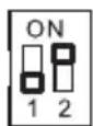
Increase 20% speed of FSB
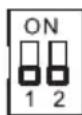
Important
• Make sure that you power off the system before setting the switch.
- When overclocking cause system instability or crash during boot. Please set the switch to default setting.
SLOTS
PCI (Peripheral Component Interconnect) Express Slot
The PCI Express slot supports the PCI Express interface expansion card.
The PCI Express 2.0 x16 supports up to 8.0 GB/s transfer rate.
The PCI Express x1 supports up to 250 MB/s transfer rate.
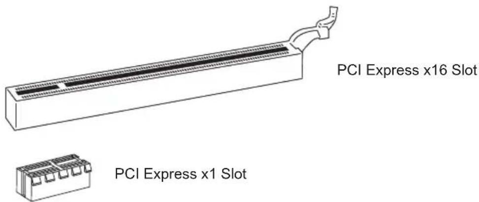
text_image
PCI Express x16 Slot PCI Express x1 SlotHybrid CrossFireX™ Technology
Hybrid CrossFireX™ technology brings multi-GPU performance capabilities by enabling an AMD® integrated graphics processor and a discrete graphics processor to operate simultaneously with combined output to a single display for blisteringly-fast frame rates. Unleash the graphics performance.
System Request
- Hybrid CrossFireX ^™ is only supported with the Vista operating system.
- Graphic card based on an ATI Radeon™ HD 2400 Series2, ATI Radeon™ HD 3400 Series or ATI Mobility Radeon™ HD 3400 Series graphics processor.
- Mainboard based on an AMD® integrated chipset.
Enabling Hybrid CrossFireX™ Technology
Power off the system and install the ATI graphic card that supports Hybrid CrossFireX™ technology. After then, power on the system and install the driver that Hybrid CrossFi - reX™ technology. Restart the system and wait for the ATI Icon to show in the System Tray. Click the icon and then the following aspect appears in Catalyst Control Center:

text_image
10:28 AMClick this icon.
Select the Advanced View from the view drop menu.1.
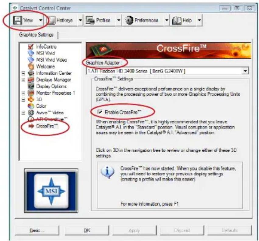
text_image
Catalyst Control Center View Hotkeys Profiles Preferenose Help Graphics Settings InfoCentre MSI Vivid MSI Vivid Video Welcome Information Center Display Manager Display Options Monitor Properties 1 3D Color Avivo™ Video ATI Overblue™ CrossFire™ Graphics Adapter 1.ATI Radeon HD 3400 Senca [BonQ G2400W] CrossFire™ Settings CrossFire™ delivers exceptional performance on a single display by combining the processing power of two or more Graphics Processing Units (GPUs). Enable CrossFire™ When enabling CrossFire™, it is highly recommended that you leave Catalyst® A.I. in the "Standard" position. Visual corruption or application issues may be seen in the Catalyst® A.I. "Advanced" position. Click on 3D in the navigation tree to review or change either of these 3D settings. CrossFire™ has now started. When you disable this feature, you will need to restore your previous display settings (creating a profile will make this easier). For more information, press F1 Basic... OK Apply Discard Defaults- From the "Graphics Settings" tree in the Catalyst Control Center, click Cross-Fire™.
- From the "Graphics Adapter" list, select the graphics card that acts as the Display GPU.
- Select "Enable CrossFireTM".
- Click Apply.
When Hybrid CrossFireX ^™ is enabled, GPU Accelerated Physics is automatically disabled for all cards in the configuration as are all displays except the one used by Hybrid CrossFireX ^™ .
More details please refer to http://game.amd.com/us-en/crossfirex_hybrid.aspx
Important
Changing integrated graphic memory operating mode may cause Hybrid CrossFireX™ fail. To avoid the issue, please follow the steps below to setup the system:
- Disable the Hybrid CrossFireX™ in Catalyst Control Center.
- Reboot into BIOS.
- Select the option in Advanced BIOS Features -> Chipset Feature -> On-Chip VGA.
- Save BIOS settings and reboot.
- Enable the Hybrid CrossFireX™ in Catalyst Control Center.
PCI (Peripheral Component Interconnect) Slot
The PCI slot supports LAN card, SCSI card, USB card, and other add-on cards that comply with PCI specifications.
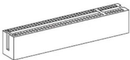
natural_image
Isometric line drawing of a rectangular electronic component with internal grid structure (no text or symbols)32-bit PCI Slot
Important
When adding or removing expansion cards, make sure that you unplug the power supply first. Meanwhile, read the documentation for the expansion card to configure any necessary hardware or software settings for the expansion card, such as jumpers, switches or BIOS configuration.
PCI Interrupt Request Routing
The IRQ, acronym of interrupt request line and pronounced I-R-Q, are hardware lines over which devices can send interrupt signals to the microprocessor. The PCI IRQ pins are typically connected to the PCI bus pins as follows:
| Order1 Order2 Order3 Order4 | |
| PCI Slot1 INT | E# INT F# INT G# INT H# |
| PCI Slot2 INT | F# INT G# INT H# INT E# |
LED STATUS INDICATORS
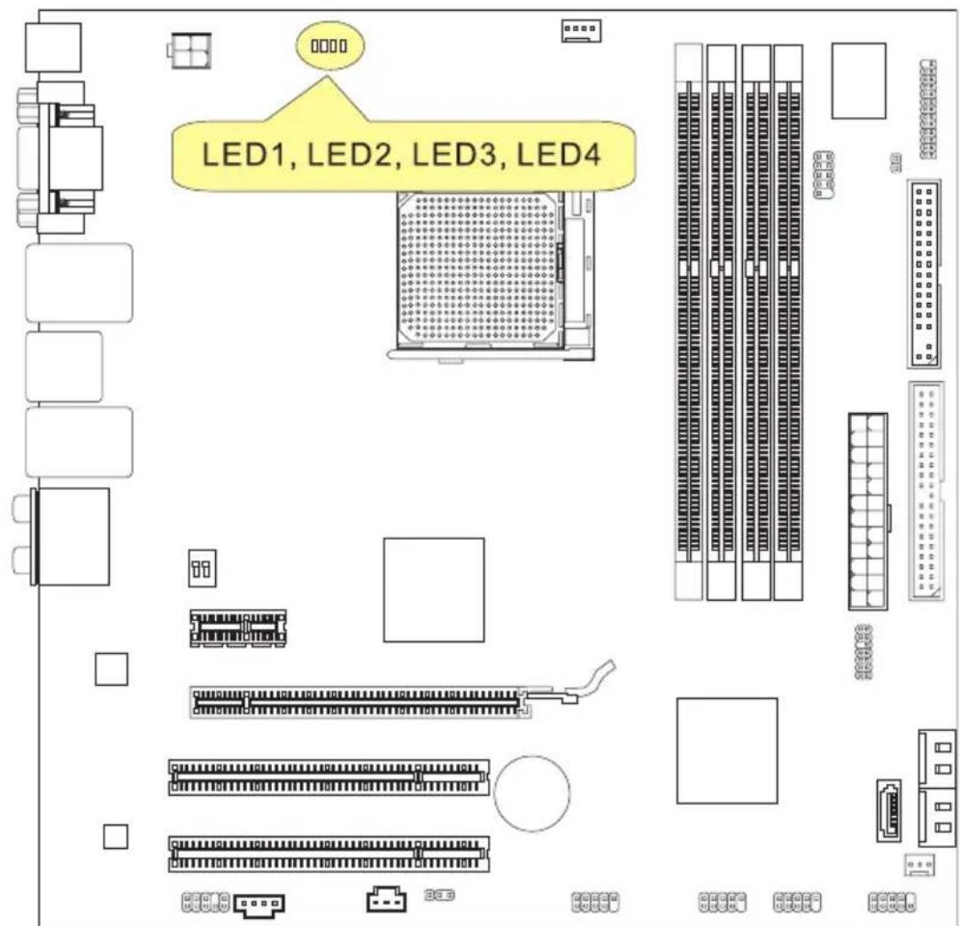
text_image
LED1, LED2, LED3, LED4CPU Phase LEDs: LED1, LED2, LED3, LED4
These LEDs indicate the current CPU power phase mode. Follow the instructions below to read.
Blue light Off
| LED1 | LED2 | LED3 | LED4 | Mode |
| CPU is in 1 phase power mode. | ||||
| CPU is in 4 phase power mode. |
Chapter 3 BIOS Setup
This chapter provides information on the BIOS Setup program and allows you to configure the system for optimum use.
You may need to run the Setup program when:
■ An error message appears on the screen during the system booting up, and requests you to run SETUP.
■ You want to change the default settings for customized features.
ENTERING SETUP
Power on the computer and the system will start POST (Power On Self Test) process. When the message below appears on the screen, press key to enter Setup.
Press DEL to enter SETUP
If the message disappears before you respond and you still wish to enter Setup, restart the system by turning it OFF and On or pressing the RESET button. You may also re-start the system by simultaneously pressing
Important
- The items under each BIOS category described in this chapter are under continuous update for better system performance. Therefore, the description may be slightly different from the latest BIOS and should be held for reference only.
- Upon boot-up, the 1st line appearing after the memory count is the BIOS version. It is usually in the format:
A7596AMS V2.1 070509 where:
1st digit refers to BIOS maker as A = AMI, W = AWARD, and P = PHOENIX.
2nd - 5th digit refers to the model number.
6th digit refers to the chipset as I = Intel, N = NVIDIA, A = AMD and V = VIA.
7th - 8th digit refers to the customer as MS = all standard customers.
V2.1 refers to the BIOS version.
070509 refers to the date this BIOS was released.
Control Keys
| <↑> Move to the previous item | |
| <↓> Move to the next item | |
| <←> Move to the item in the left hand | |
| <→> Move to the item in the right hand | |
| Select the item | |
| Jumps to the Exit menu or returns to the main menu from a submenu | |
| <+/PU> | Increase the numeric value or make changes |
| <-/PD> | Decrease the numeric value or make changes |
| General Help | |
| Load Optimized Defaults | |
| Load Fail-Safe Defaults | |
| Save all the CMOS changes and exit | |
Getting Help
After entering the Setup menu, the first menu you will see is the Main Menu.
Main Menu
The main menu lists the setup functions you can make changes to. You can use the arrow keys (↑↓) to select the item. The on-line description of the highlighted setup function is displayed at the bottom of the screen.
Sub-Menu
If you find a right pointer symbol (as shown in the right view) appears to the left of certain fields that means a sub-menu can be launched from this field. A sub-menu contains additional options for a field parameter. You can use arrow keys (↑↓) to highlight the

field and press
General Help
The BIOS setup program provides a General Help screen. You can call up this screen from any menu by simply pressing
THE MAIN MENU
| Standard CMOS FeaturesAdvanced BIOS FeaturesIntegrated PeripheralsPower Management SetupH/V MonitorGreen PowerBIOS Setting Password | Cell MenuM-FlashUser SettingsLoad Fail-Safe DefaultsLoad Optimized DefaultsSave & Exit SetupExit Without Saving |
| ↑↓↔:Move Enter:Select +/-/:Value F10:Save ESC:Exit F1:General HelpF4:CPU Spec F5:Memory-Z F8:Fail-Safe Defaults F6:Optimized Defaults | |
| Configure Time and Date. Display System Information...v02.61 (C) Copyright 1985-2006, American Megatrends, Inc. | |
▶ Standard CMOS Features
Use this menu for basic system configurations, such as time, date etc.
▶ Advanced BIOS Features
Use this menu to setup the items of the BIOS special enhanced features.
▶ Integrated Peripherals
Use this menu to specify your settings for integrated peripherals.
▶ Power Management Setup
Use this menu to specify your settings for power management.
▶ H/W Monitor
This entry shows your PC health status.
▶ Green Power
Use this menu to specify the power phase.
▶ BIOS Setting Password
Use this menu to set the password for BIOS.
▶ Cell Menu
Use this menu to specify your settings for frequency/voltage control and overclocking.
▶ M-Flash
Use this menu to read/ flash the BIOS from storage drive (FAT/ FAT32 format only).
▶ User Settings
Use this menu to save/ load your settings to/ from CMOS for BIOS.
▶ Load Fail-Safe Defaults
Use this menu to load the default values set by the BIOS vendor for stable system performance.
▶ Load Optimized Defaults
Use this menu to load the default values set by the mainboard manufacturer specifically for optimal performance of the mainboard.
▶ Save & Exit Setup
Save changes to CMOS and exit setup.
▶ Exit Without Saving
Abandon all changes and exit setup.
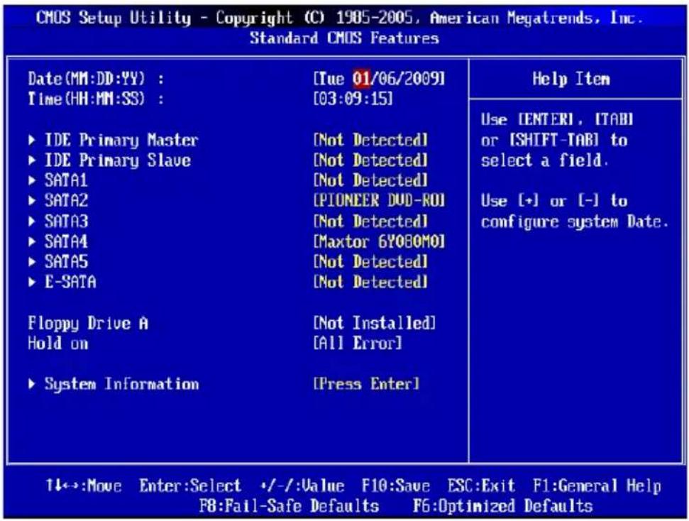
STANDARD CMOS FEATURES
The items in Standard CMOS Features Menu include some basic setup items. Use the arrow keys to highlight the item and then use the
text_image
CMOS Setup Utility - Copyright (C) 1905-2005, American Megatrends, Inc. Standard CMOS Features Date(MM:DD:YY) : [Tue 01/06/2009] Time(HH:MM:SS) : [03:09:15] ► IDE Primary Master [Not Detected] ► IDE Primary Slave [Not Detected] ► SATA1 [Not Detected] ► SATA2 [PIONEER DVD-ROI] ► SATA3 [Not Detected] ► SATA4 [Maxtor 6Y08OMO] ► SATA5 [Not Detected] ► E-SATA [Not Detected] Floppy Drive A [Not Installed] Hold on [All Error] ► System Information [Press Enter] Help Item Use ENTERI, ITABI or [SHIFT-TAB] to select a field. Use (+) or (-) to configure system Date. 11:→:Move Enter:Select +/-:Value F10:Save ESC:Exit F1:General Help F8:Fail-Safe Defaults F6:Optimized Defaults▶ Date (MM:DD:YY)
This allows you to set the system to the date that you want (usually the current date). The format is
[day] Day of the week, from Sun to Sat, determined by BIOS. Read-only.
[month] The month from Jan. through Dec.
[date] The date from 1 to 31 can be keyed by numeric function keys.
[year] The year can be adjusted by users.
▶ Time (HH:MM:SS)
This allows you to set the system time that you want (usually the current time). The time format is
▶ SATA1\~6 & 7/8 & 9/10 & IDE Primary Master/ Slave & E-SATA1/2
Press
text_image
CMOS Setup Utility - Copyright (C) 1985-2005, American Megatrends, Inc. SATA4 SATA4 Device :Hard Disk Vendor :Maxtor 6Y080M0 Size :81GB LBA/Large Mode [Auto] DMA Mode [Auto] Hard Disk S.M.A.R.T. [Auto] Help Item Disabled: Disables LBA Mode. Auto: Enables LBA Mode if the device supports it and the device is not already formatted with LBA▶ Device / Vendor / Size
It will show the device information that you connected to the SATA connector.
▶LBA/Large Mode
This allows you to enable or disable the LBA Mode. Setting to Auto enables LBA mode if the device supports it and the devices is not already formatted with LBA mode disabled.
▶ DMA Mode
Select DMA Mode.
▶Hard Disk S.M.A.R.T.
This allows you to activate the S.M.A.R.T. (Self-Monitoring Analysis & Reporting Technology) capability for the hard disks. S.M.A.R.T is a utility that monitors your disk status to predict hard disk failure. This gives you an opportunity to move data from a hard disk that is going to fail to a safe place before the hard disk becomes offline.
Important
IDE Primary Master/ Slave, SATA 1\~5 & E-SATA are appearing when you connect the HD devices to the IDE/ SATA/ E-SATA connectors on the mainboard.
▶ Floppy Drive A
This item allows you to set the type of floppy drives installed.
BIOS Setup
▶ Hold On
The setting determines whether the system will stop if an error is detected at boot. When the system stops for the errors preset, it will halt on for 15 seconds and then automatically resume its operation.
[All Error] The system stops when any error is detected.
[No Error] The system does not stop for any detected error.
▶ System Information
Press
text_image
CMOS Setup Utility - Copyright (C) 1985-2005, American Megatrends, Inc. System Information AMD Phenom(tm) II X4 955 Processor CPUID/MicroCode 0100F42h/01000006h CPU Frequency 3.20GHz(200x16) BIOS Version U2.0B14 07022009 Physical Memory 512MB Cache Size 2048KB L3 Cache Size 6144KB Help ItemThis sub-menu shows the CPU information, BIOS version and memory status of your system (read only).
ADVANCED BIOS FEATURES

text_image
CMOS Setup Utility - Copyright (C) 1985-2005, American Megatrends, Inc. Advanced BIOS Features BIOS Flash Protection [Disabled] Full Screen Logo Display [Enabled] Quick Booting [Enabled] Boot Up Num-Lock LED [On] IOAPIC Function [Enabled] MPS Table Version [1.4] Primary Graphic's Adapter [PCI-E] PCI Latency Timer [64] ► CPU Feature [Press Enter] ► Chipset Feature [Press Enter] ► Boot Sequence [Press Enter] ► Trusted Computing [Press Enter] Help Item Options Disabled Enabled 1←→:Move Enter:Select +/-:Value F10:Save ESC:Exit F1:General Help F8:Fail-Safe Defaults F6:Optimized Defaults▶ BIOS Flash Protection
This function protects the BIOS from accidental corruption by unauthorized users or computer viruses. When enabled, the BIOS' data cannot be changed when attempting to update the BIOS with a Flash utility. To successfully update the BIOS, you will need to disable this Flash BIOS Protection function. You should enable this function at all times. The only time when you need to disable it is when you want to update the BIOS. After updating the BIOS, you should immediately re-enable it to protect it against viruses.
▶ Full Screen Logo Display
This item enables this system to show the company logo on the boot-up screen. Settings are:
[Enabled] Shows a still image (logo) on the full screen at boot.
[Disabled] Shows the POST messages at boot.
▶ Quick Booting
Setting the item to [Enabled] allows the system to boot within 10 seconds since it will skip some check items.
▶ Boot Up Num-Lock LED
This setting is to set the Num Lock status when the system is powered on. Setting to [On] will turn on the Num Lock key when the system is powered on. Setting to [Off] will allow users to use the arrow keys on the numeric keypad.
▶ IOAPIC Function
This field is used to enable or disable the APIC (Advanced Programmable Interrupt Controller). Due to compliance with PC2001 design guide, the system is able to run in APIC mode. Enabling APIC mode will expand available IRQ resources for the system.
▶ MPS Table Version
This field allows you to select which MPS (Multi-Processor Specification) version to be used for the operating system. You need to select the MPS version supported by your operating system. To find out which version to use, consult the vendor of your operating system.
▶ Primary Graphic's Adapter
This setting specifies which graphic card is your primary graphics adapter.
▶ PCI Latency Timer
This item controls how long each PCI device can hold the bus before another takes over. When set to higher values, every PCI device can conduct transactions for a longer time and thus improve the effective PCI bandwidth. For better PCI performance, you should set the item to higher values.
▶ CPU Feature
Press
text_image
CMOS Setup Utility - Copyright (C) 1985-2005, American Megatrends, Inc. CPU Feature SUM Support [Enabled] Help Item CIE Support [Disabled]▶C1E Support
To enable this item to read the CPU power consumption while idle. Not all processors support Enhanced Halt state (C1E).
▶ SVM Support
This item is used to enable/ disable SVM.
▶ Chipset Feature
Press
text_image
CMOS Setup Utility - Copyright (C) 1985-2005, American Megatrends, Inc. Chipset Feature HPET [Enabled] On-Chip UGA [UMA] UGA Share Memory [Auto] UMA Location [Above] Help Item OptionsHPET
The HPET (High Precision Event Timers) is a component that is part of the chipset. You can to enable it, and will provide you with the means to get to it via the various ACPI methods.
On-chp VGA
This item specifies whether to allocate the memory for onboard VGA from the system memory or slideport memory. Setting to [UMA], allocates the system share memory for onboard VGA.
▶VGA Share Memory
The system shares memory to the onboard VGA card. This setting controls the exact memory size shared to the VGA card.
▶UMA Location
This item is used to select the location of UMA to avoid over-lapping with the other data blocks in system memory.
▶Boot Sequence
Press
text_image
CMOS Setup Utility - Copyright (C) 1905-2005, American Megatrends, Inc. Boot Sequence 1st Boot Device [USD:MITSUMI USI] Boot From Other Device [Yes] Help Item Specifies the boot▶1st Boot Device
This item allows you to set the first boot device where BIOS attempts to load the disk operating system.
▶Boot From Other Device
Setting the option to [Yes] allows the system to try to boot from other device, if the system falls to boot from 1st boot device.
▶Trusted Computing
Press

text_image
CMOS Setup Utility - Copyright (C) 1985-2005, American Megatrends, Inc. Trusted Computing Clearing The TPM [Press Enter] Help Item▶ Clearing the TPM
Press Enter to clear the TPM status.
INTEGRATED PERIPHERALS
text_image
CMOS Setup Utility - Copyright (C) 1985-2005, American Megatrends, Inc. Integrated Peripherals USB Controller [Enabled] USB Device Legacy Support [Enabled] Onboard LAN Controller [Enabled] LAN Option ROM [Disabled] HD Audio Controller [Enabled] ► On-Chip ATA Devices [Press Enter] ► I/O Devices [Press Enter] Help Item Options Disabled Enabled 14:→:Move Enter:Select +/-:Value F10:Save ESC:Exit F1:General Help F4:CPU Spec F5:Memory-2 F8:Fail-Safe Defaults F6:Optimized Defaults▶ USB Controller
This setting allows you to enable/disable the onboard USB 1.1/2.0 controller.
▶ USB Device Legacy Support
Select [Enabled] if you need to use a USB-interfaced device in the operating system.
▶ Onboard LAN Controller
This setting allows you to enable/disable the onboard LAN controller.
▶ LAN Option ROM
This item is used to decide whether to invoke the Boot ROM of the onboard LAN.
▶ HD Audio Controller
This setting is used to enable/disable the onboard audio controller.
▶ On-Chip ATA Devices
Press
text_image
CMOS Setup Utility - Copyright (C) 1905-2005, American Megatrends, Inc. On-Chip ATA Devices PCI IDE BusMaster [Disabled] On-Chip SATA Controller [Enabled] RAID Mode [IDE] Help Item ENABLED: BIOS uses▶ PCI IDE BusMaster
This item allows you to enable/ disable BIOS to used PCI busmastering for reading/writing to IDE drives.
▶ OnChip SATA Controller
This item allows users to enable or disable the SATA controller.
▶RAID Mode
This item is used to select mode for SATA connectors.
▶ I/O Devices
Press
text_image
CMOS Setup Utility - Copyright (C) 1985-2005, American Megatrends, Inc. I/O Devices COM Port 1 [3F8/IRQ4] Help Item Parallel Port [378] Parallel Port Mode [BI-Directional] Allows BIOS to Select▶COM Port 1
Select an address and corresponding interrupt for the serial port.
▶Parallel Port
There is a built-in parallel port on the on-board Super I/O chipset that provides Standard, ECP, and EPP features. It has the following options:
[Disabled]
[3BC/IRQ7] Line Printer port 0
[278/IRQ5] Line Printer port 2
[378/IRQ7] Line Printer port 1
▶Parallel Port Mode
[SPP] Standard Parallel Port
[EPP] Enhanced Parallel Port
[ECP] Extended Capability Port
[ECP + EPP] Extended Capability Port + Enhanced Parallel Port
[Bi-Directional]
To operate the onboard parallel port as Standard Parallel Port only, choose [SPP]. To operate the onboard parallel port in the EPP mode simultaneously, choose [EPP]. By choosing [ECP], the onboard parallel port will operate in ECP mode only. Choosing [ECP + EPP] will allow the onboard parallel port to support both the ECP and EPP modes simultaneously.
POWER MANAGEMENT SETUP
text_image
CMOS Setup Utility - Copyright (C) 1985-2005, American Megatrends, Inc. Power Management Setup ACPI Function [Enabled] ACPI Standby State [S1] Power Button Function [Power OFF] Restore On AC Power Loss [Off] ► Wake Up Event Setup [Press Enter] Help Item Enable / Disable ACPI support for Operating System. ENABLE: If OS supports ACPI. DISABLE: If OS does not support ACPI. 11:→:Move Enter:Select +/-:Value F10:Save ESC:Exit F1:General Help F8:Fail-Safe Defaults F6:Optimized DefaultsImportant
S3-related functions described in this section are available only when the BIOS supports S3 sleep mode.
▶ ACPI Function
This item is to activate the ACPI (Advanced Configuration and Power Management Interface) Function. If your operating system is ACPI-aware, such as Windows 98SE/2000/ME/XP, select [Enabled].
▶ ACPI Standby State
This item specifies the power saving modes for ACPI function. If your operating system supports ACPI, such as Windows 2000/ XP, you can choose to enter the Standby mode in S1(POS) or S3(STR) fashion through the setting of this field. Settings are:
[S1] The S1 sleep mode is a low power state. In this state, no system context is lost (CPU or chipset) and hardware maintains all sys - tem's context.
[S3] The S3 sleep mode is a lower power state where the in formation of system configuration and open applications/files is saved to main memory that remains powered while most other hardware components turn off to save energy. The information stored in memory will be used to restore the system when a "wake up" event occurs.
▶ Power Button Function
This feature sets the function of the power button. Settings are:
[Power Off] The power button functions as normal power off button.
[Suspend] When you press the power button, the computer enters suspend/sleep mode, but if the button is pressed for more than four seconds, the computer is turned off.
This item specifies whether your system will reboot after a power failure or interrupt occurs. Settings are:
[Off] Always leaves the computer in the power off state.
[On] Always leaves the computer in the power on state.
[Last State] Restore the system to the status before power failure or interrupt occurred.
▶ Wake Up Event Setup
Press
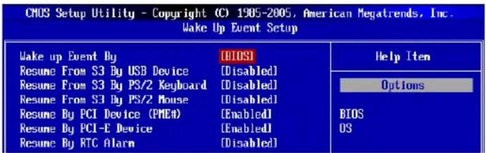
text_image
CMOS Setup Utility - Copyright (C) 1985-2005, American Megatrends, Inc. Wake Up Event Setup Wake up Event By Resume From S3 By USB Device Resume From S3 By PS/2 Keyboard Resume From S3 By PS/2 Mouse Resume By PCI Device (PMEA) Resume By PCI-E Device Resume By RTC Alarm [BIOS] [Disabled] [Disabled] [Disabled] [Enabled] [Enabled] [Disabled] Help Item Options BIOS OS▶ Wake Up Event By
Setting to [BIOS] activates the following fields, and use the following fields to set the wake up events. Setting to [OS], the wake up events will be defined by OS.
▶Resume From S3 By USB Device
The item allows the activity of the USB device to wake up the system from S3 (Suspend to RAM) sleep state.
▶Resume From S3 By PS/2 Keyboard / Mouse
These items determine whether the system will be awakened from what power saving modes when input signal of the PS/2 keyboard/ mouse is detected.
▶Resume By PCI Device (PME#)
When set to [Enabled], the feature allows your system to be awakened from the power saving modes through any event on PME (Power Management Event).
▶Resume By PCI-E Device
When set to [Enabled], the feature allows your system to be awakened from the power saving modes through any event on PCIE device.
▶Resume By RTC Alarm
The field is used to enable or disable the feature of booting up the system on a scheduled time/date.
H/W MONITOR
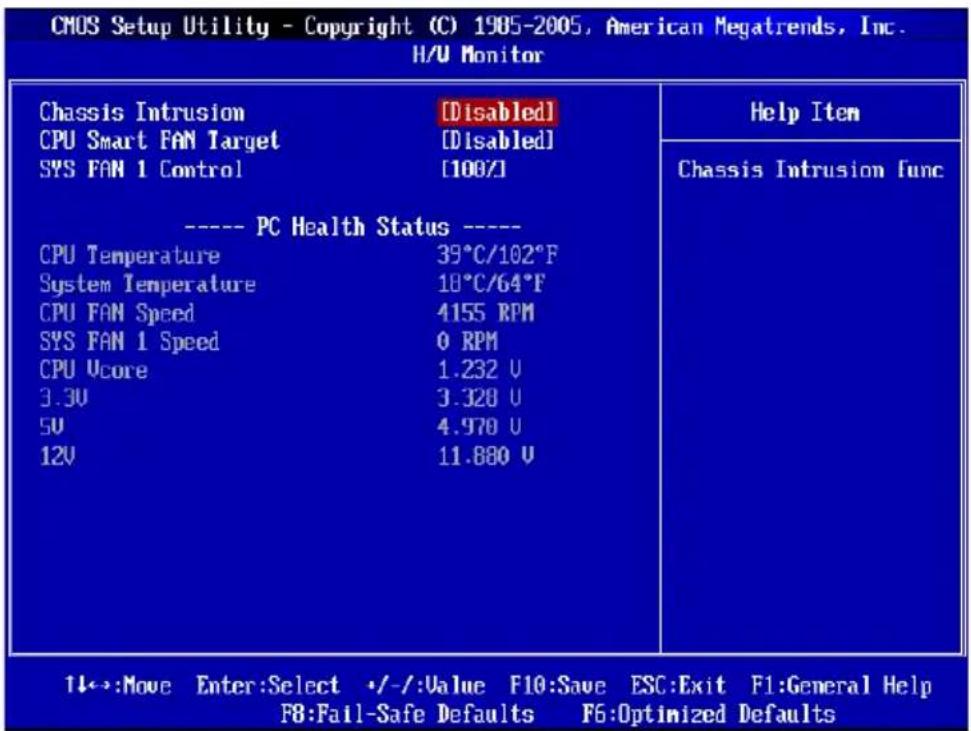
text_image
CMOS Setup Utility - Copyright (C) 1985-2005, American Megatrends, Inc. H/U Monitor Chassis Intrusion [Disabled] CPU Smart FAN Target [Disabled] SYS FAN 1 Control [100%] ---- PC Health Status ---- CPU Temperature 39°C/102°F System Temperature 18°C/64°F CPU FAN Speed 4155 RPM SYS FAN 1 Speed 0 RPM CPU Ucore 1.232 U 3.3U 3.328 U 5U 4.970 U 12U 11.880 U Help Item Chassis Intrusion func 1←→:Move Enter:Select +/-Value F10:Save ESC:Exit F1:General Help F8:Fail-Safe Defaults F6:Optimized Defaults▶ Chassis Intrusion
The field enables or disables the feature of recording the chassis intrusion status and issuing a warning message if the chassis is once opened. To clear the warning message, set the field to [Reset]. The setting of the field will automatically return to [Enabled] later.
▶ CPU Smart FAN Target
The mainboard provides the Smart Fan function which can control the CPU fan speed automatically depending on the current temperature to keep it with in a specific range. You can enable a fan target value here. If the current CPU fan temperature reaches to the target value, the smart fan function will be activated. It provides several sections to speed up for cooling down automatically.
▶ SYS FAN 1 Control
This item allows users to select how percentage of speed for the SYSFAN1.
▶ PC Health Status
▶CPU/ System Temperature, CPU FAN/ SYS FAN 1 Speed, CPU Vcore, 3.3V, 5V, 12V
These items display the current status of all of the monitored hardware devices/components such as CPU voltage, temperatures and all fans' speeds.
GREEN POWER
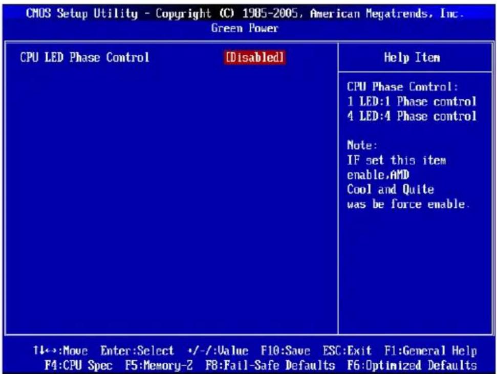
text_image
CMOS Setup Utility - Copyright (C) 1985-2005, American Megatrends, Inc. Green Power CPU LED Phase Control [Disabled] Help Item CPU Phase Control: 1 LED:1 Phase control 4 LED:4 Phase control Note: IF set this item enable,AMD Cool and Quite was be force enable. 1←→:Move Enter:Select +/-Value F10:Save ESC:Exit F1:General Help F4:CPU Spec F5:Memory-2 F8:Fail-Safe Defaults F6:Optimized Defaults▶ CPU LED Phase Control
When it set to [Enabled], the AMD Cool and Quite was be force enable.
BIOS SETTING PASSWORD
When you select this function, a message as below will appear on the screen:

text_image
Enter New PasswordType the password, up to six characters in length, and press
To clear a set password, just press
When a password has been set, you will be prompted to enter it every time you try to enter Setup. This prevents an unauthorized person from changing any part of your system configuration.
CELL MENU
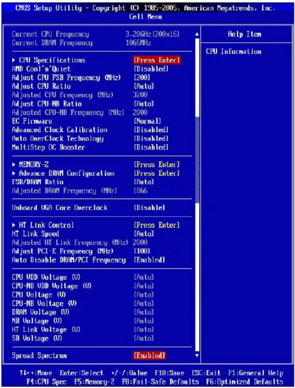
text_image
CMOS Setup Utility - Copyright (C) 1985-2005, American Megatrends, Inc. Cell Menu Current CPU Frequency 3.20GHz (200x16) Current DRAM Frequency 1066MHz ► CPU Specifications [Press Enter] AMD Cool'n'Quiet [Disabled] Adjust CPU FSB Frequency (MHz) [200] Adjust CPU Ratio [Auto] Adjusted CPU Frequency (MHz) 3200 Adjust CPU-NB Ratio [Auto] Adjusted CPU-NB Frequency (MHz) 2000 EC Firmware [Normal] Advanced Clock Calibration [Disabled] Auto OverClock Technology [Disabled] MultiStep OC Booster [Disabled] ► MEMORY-2 [Press Enter] ► Advance DRAM Configuration [Press Enter] FSB/DRAM Ratio [Auto] Adjusted DRAM Frequency (MHz) 1066 Onboard UGA Core Overclock [Disable] ► HT Link Control [Press Enter] HT Link Speed [Auto] Adjusted HT Link Frequency (MHz) 2000 Adjust PCI-E Frequency (MHz) [100] Auto Disable DRAM/PCI Frequency [Enabled] CPU UDD Voltage (U) [Auto] CPU-NB UDD Voltage (U) [Auto] CPU Voltage (U) [Auto] CPU-NB Voltage (U) [Auto] DRAM Voltage (U) [Auto] NB Voltage (U) [Auto] HT Link Voltage (U) [Auto] SB Voltage (U) [Auto] Spread Spectrum [Enabled] Help Item CPU Information T←→:Move Enter:Select +/-:Value F10:Save ESC:Exit F1:General Help F4:CPU Spec F5:Memory-2 F8:Fail-Safe Defaults F6:Optimized DefaultsImportant
Change these settings only if you are familiar with the chipset.
▶ Current CPU / DRAM Frequency
These items show the current clocks of CPU and Memory speed. Read-only.
▶ CPU Specifications
Press
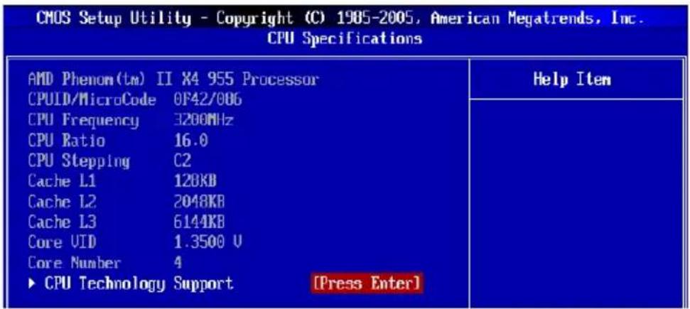
text_image
CMOS Setup Utility - Copyright (C) 1985-2005, American Megatrends, Inc. CPU Specifications AMD Phenom(tm) II X4 955 Processor CPULD/MicroCode 0F42/006 CPU Frequency 3200MHz CPU Ratio 16.0 CPU Stepping C2 Cache L1 120KB Cache L2 2048KB Cache L3 6144KB Core VID 1.3500 U Core Number 4 ► CPU Technology Support [Press Enter] Help Item▶CPU Technology Support
Press
| CMOS Setup Utility - Copyright (C) 1985-2005, American Megatrends, Inc. CPU Technology Support | |
| MMX (TM) YES | Help Item |
| SSE Extensions YES | |
| SSE2 Extensions YES | |
| SSE3 Extensions YES | |
| SSE4 Extensions N/A | |
| SSE5 Extensions N/A | |
| Page Size Extension(PSE) YES | |
| Page Attribute Table(PAT) YES | |
| 3D-NOV YES | |
| SUM YES | |
▶ AMD Cool'n'Quiet
The Cool'n'Quiet technology can effectively and dynamically lower CPU speed and power consumption.
Important
To ensure that Cool'n'Quiet function is activated and will be working properly, it is required to double confirm that:
- Run BIOS Setup, and select Cell Menu. Under Cell Menu, find AMD Cool'n'Quiet, and set this item to "Enabled".
- Enter Windows, and select [Start]->[Settings]->[Control Panel]->[Power Options]. Enter Power Options Properties tag, and select Minimal Power Management under Power schemes.
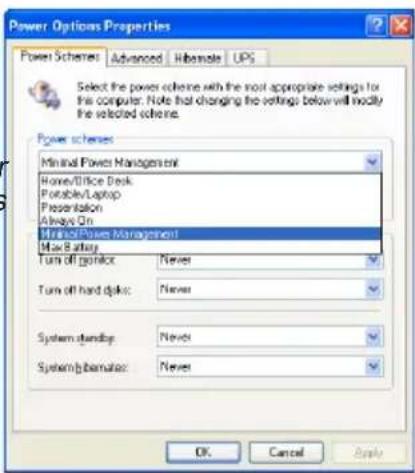
text_image
Power Options Properties Power Schemes: Advanced Hibernate UPS Select the power scheme with the most appropriate settings for the computer. Note that changing the settings below will modify the selected scheme. Power schemes Minimal Power Management Home/Office Desk Portable/Laptop Presentation Always On Minimal/Power Management Max Battery Turn off GPIO: Never Turn off hard GPIO: Never System-bandUp: Never System-bandBase: Never OK Cancel Apply▶ Adjust CPU FSB Frequency (MHz)
This item allows you to select the CPU Front Side Bus clock frequency (in MHz).
▶ Adjust CPU Ratio
This item is used to adjust CPU clock multiplier (ratio). It is available only when the processor supports this function.
▶ Adjusted CPU Frequency (MHz)
It shows the adjusted CPU frequency. Read-only.
▶ Adjust CPU-NB Ratio
This item is used to adjust CPU-NB ratio.
▶ Adjusted CPU NB Frequency (MHz)
It shows the adjusted CPU NB frequency. Read-only.
▶ Advanced Clock Calibration
This item is for overclock. Setting to [Enabled] allows you to set the CPU Ratio higher. It is available only when the processor supports this function.
▶ Auto OverClock Technology
Setting this item to [Max FSB] allows the system to detect the FSB limitation for over-clocking automatically. If overclocking fails, you can try the lower FSB clock for overclocking successfully.
▶ Multi-step OC Booster
This item is used to avoid the BIOS might crash with overclocking.
[Disabled] Disable this item, apply OC settings during POST.
[Mode 1] Slight OC during POST and then apply full OC when loading the OS
[Mode 2] Load the OS then apply the OC settings.
▶ Memory-Z
Press

text_image
CMOS Setup Utility - Copyright (C) 1985-2005, American Megatrends, Inc. MEMORY-Z ► DIMM2 Memory SPD Information [Press Enter] Help Item▶DIMM1\~4 Memory SPD Information
Press
▶ Advance DRAM Configuration
Press
| DRAM Timing Mode [Auto]DRAM Drive Strength [Auto]DRAM Advance Control [Auto]1T/2T Memory Timing [Auto]DCT Unganged Mode [Enabled]Bank Interleaving [Auto]Power Down Enable [Disabled]MemClk Iristate C3/ATLUID [Disabled] | Help ItemWhen you change this item to Auto, system will read the data inside SPD "Serial Presence Detect" and run suitable memory |
▶DRAM Timing Mode
This field has the capacity to automatically detect all of the DRAM timing.
▶DRAM Drive Strength
This item allows you to control the memory data bus' signal strength. Increasing the drive strength of the memory bus can increase stability during overclocking.
▶DRAM Advance Control
This field has the capacity to automatically detect the advanced DRAM timing. If you set this field to [DCT 0], [DCT 1] or [Both], some fields will appear and selectable.
▶1T/2T Memory Timing
This item controls the SDRAM command rate. Select [1T] makes SDRAM signal controller to run at 1T (T=clock cycles) rate. Selecting [2T] makes SDRAM signal controller run at 2T rate.
▶DCT Unganged Mode
This feature is used to Integrate two 64-bit DCTs into a 128-bit interface.
▶ Bank Interleaving
Bank Interleaving is an important parameter for improving overclocking capability of memory. It allows system to access multiple banks simultaneously.
▶ Power Down Enable
This is a memory power-saving technology. When the system does not access memory over a period of time, it will automatically reduce the memory power supply.
▶MemClk Tristate C3/ATLVID
This setting allows you to enable/disable the MemClk Tristating during C3 and ATLVID.
▶ FSB/DRAM Ratio
This item allows you to select the ratio of FSB/ DRAM.
▶ Adjusted DRAM Frequency (MHz)
It shows the adjusted Memory frequency. Read-only.
▶ Onboard VGA Core Overclock
This item allows you to overclock the onboard VGA.
▶ Onboard VGA Clock
This item will appear when Onboard VGA Over Clock sets to [Enabled]. It allows you to adjust the onboard VGA clock.
▶ HT Link Control
Press
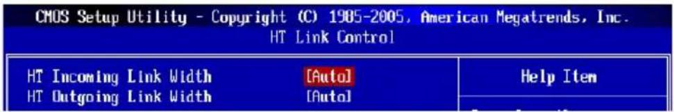
text_image
CMOS Setup Utility - Copyright (C) 1985-2005, American Megatrends, Inc. HT Link Control HT Incoming Link Width [Auto] HT Outgoing Link Width [Auto] Help Item▶HT Incoming/Outgoing Link Width
These items allow you to set the Hyper-Transport Link width. Setting to [Auto], the system will detect the HT link width automatically.
▶ HT Link Speed
This item allows you to set the Hyper-Transport Link speed. Setting to [Auto], the system will detect the HT link speed automatically.
▶ Adjusted HT Link Frequency (MHz)
It shows the adjusted HT Link frequency. Read-only.
▶ Adjust PCI-E Frequency (MHz)
This field allows you to select the PCIE frequency (in MHz).
▶ Auto Disable DRAM/PCI Frequency
When set to [Enabled], the system will remove (turn off) clocks from empty DRAM/ PCI slots to minimize the electromagnetic interference (EMI).
▶ CPU VDD Voltage (V)/ CPU-NB VDD Voltage (V)/ CPU Voltage (V)/ CPU-NB Voltage (V)/ DRAM Voltage (V)/ NB Voltage (V)/ HT Link Voltage (V)/ SB Voltage (V)
These items are used to adjust the voltage of CPU, Memory and chipset.
▶ Spread Spectrum
When the mainboard's clock generator pulses, the extreme values (spikes) of the pulses create EMI (Electromagnetic Interference). The Spread Spectrum function reduces the EMI generated by modulating the pulses so that the spikes of the pulses are reduced to flatter curves.
Important
- If you do not have any EMI problem, leave the setting at [Disabled] for optimal system stability and performance. But if you are plagued by EMI, select the value of Spread Spectrum for EMI reduction.
- The greater the Spread Spectrum value is, the greater the EMI is reduced, and the system will become less stable. For the most suitable Spread Spectrum value, please consult your local EMI regulation.
- Remember to disable Spread Spectrum if you are overclocking because even a slight jitter can introduce a temporary boost in clock speed which may just cause your over clocked processor to lock up.
M-FLASH
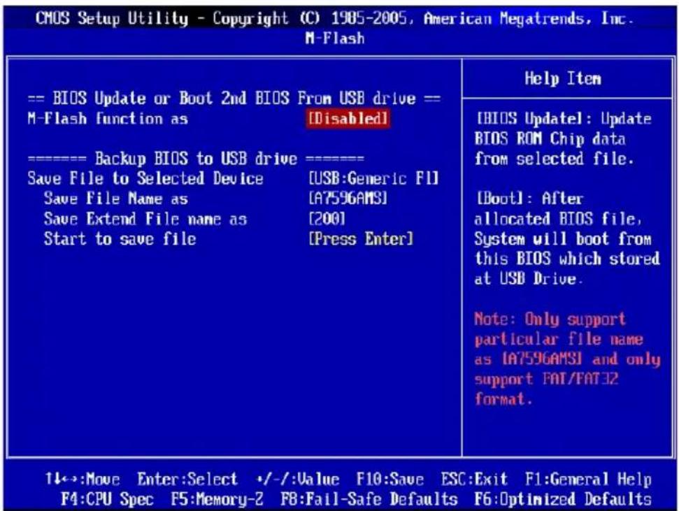
text_image
CMOS Setup Utility - Copyright (C) 1985-2005, American Megatrends, Inc. M-Flash == BIOS Update or Boot 2nd BIOS From USB drive == M-Flash function as [Disabled] -------- Backup BIOS to USB drive =----------------= Save File to Selected Device [USB:Generic FI] Save File Name as [A7596AMSI] Save Extend File name as [200] Start to save file [Press Enter] Help Item [BIOS Updatel: Update BIOS ROM Chip data from selected file. [Boot]: After allocated BIOS file, System will boot from this BIOS which stored at USB Drive. Note: Only support particular file name as [A7596AMSI] and only support FAT/FAT32 format. 1↓→:Move Enter:Select ·/−/:Value F10:Save ESC:Exit F1:General Help F4:CPU Spec F5:Memory-2 F8:Fail-Safe Defaults F6:Optimized Defaults== BIOS Update or Boot 2nd BIOS From USB drive==
▶ M-Flash function as
M-Flash function allows you to flash BIOS from USB drive/ storage drive (FAT/ FAT32 format only), or allows the system to boot from the BIOS file inside USB drive (FAT/ FAT32 format only).
[Disabled] Disable M-Flash function.
[BIOS Update] Flash BIOS via the USB/ Storage drive directly. Update BIOS ROM chip data from selected file, which was be download from official website and must be saved in the root directory of the USB/ Storage drive. It only supports particular file name, which is the official BIOS file name from us.
[Boot] After allocated particular BIOS file, system will boot from this BIOS file which saved in the root directory of USB drive. System will skip MB ROM chip data and boot with this particular BIOS inside USB drive. Note: this option is for USB drive only.
Important
- Please refer to the block diagram below about the M-Flash function.
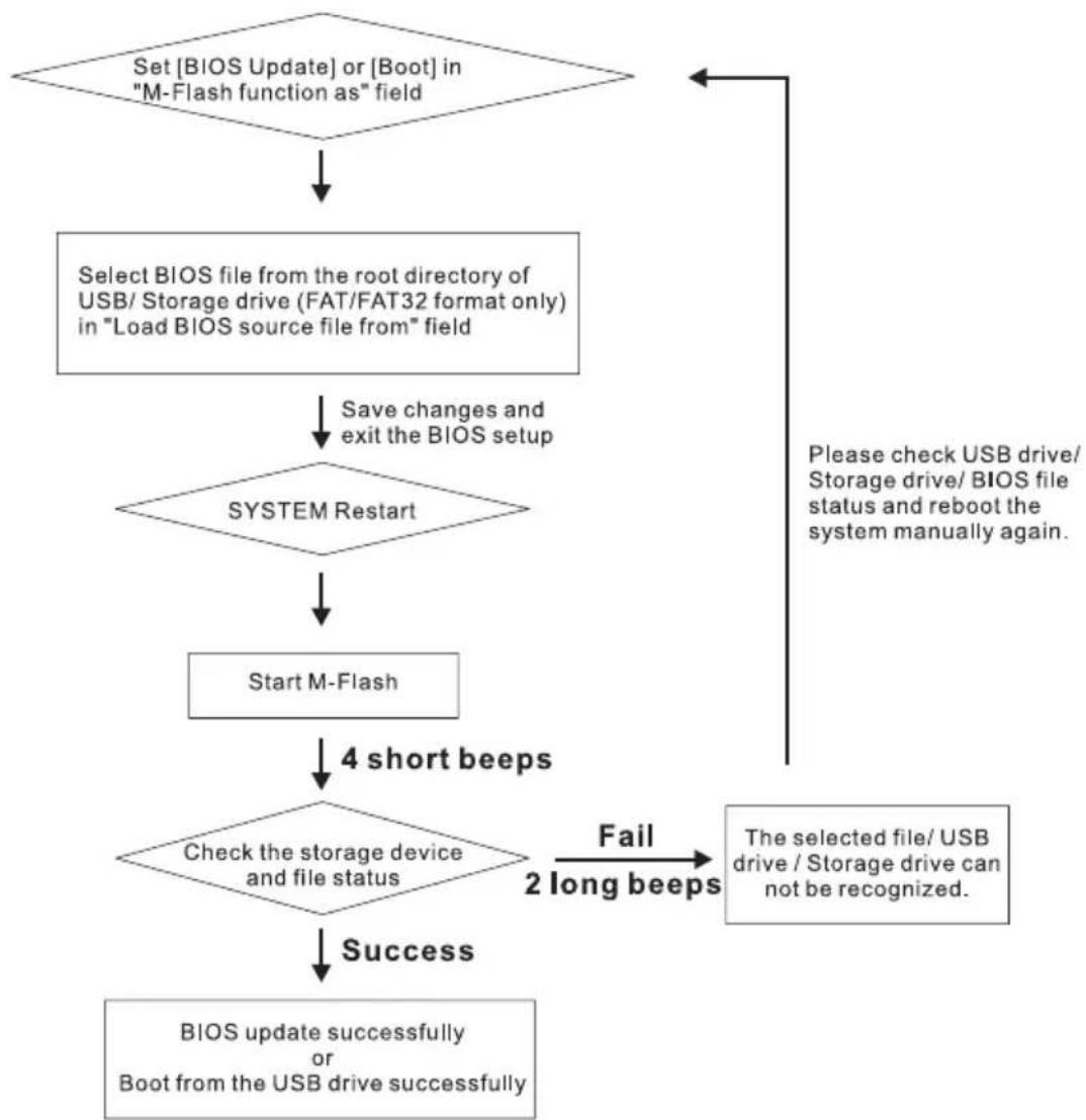
flowchart
graph TD
    A["Set [BIOS Update"] or["Boot"] in "M-Flash function as" field] --> B["Select BIOS file from the root directory of USB/ Storage drive (FAT/FAT32 format only) in "Load BIOS source file from" field"]
    B --> C["Save changes and exit the BIOS setup"]
    C --> D{SYSTEM Restart}
    D --> E["Start M-Flash"]
    E --> F["4 short beeps"]
    F --> G{Check the storage device and file status}
    G -->|Fail 2 long beeps| H["The selected file/ USB drive / Storage drive can not be recognized"]
    G -->|Success| I["BIOS update successfully or Boot from the USB drive successfully"]
    H --> J["Please check USB drive/ Storage drive/ BIOS file status and reboot the system manually again."]
    I --> K["End"]
- Due to the special design of some graphics cards will cause dark screen during M-flash operation, and you may refer the beeps from the system to confirm the current M-flash process.
BIOS Setup
▶ Load BIOS source file from
When the M-Flash function as sets to [Boot] or [BIOS Update], this item is selectable. Use this item to select particular BIOS file from the USB/ Storage (FAT/32 format only) drive.
== Backup BIOS to USB drive ==
The following fields are used to read the onboard BIOS ROM data, and save it to USB drive/ storage drive.
▶ Save File to Selected Device
Please setup a specific folder in specific USB drive/ storage drive to save BIOS file from BIOS ROM chip data. Note: it only supports FAT/ FAT32 file system drive.
▶ Save File Name as
Please setup a specific name for the BIOS file, which will be saved into the USB drive/storage drive. Note: we suggest you using the official name as the default name.
▶ Save Extend File name as
Please setup a specific extend name for the BIOS file, which will be saved into the USB drive/ storage drive. Note: we suggest you using [ROM] as default name.
▶ Start to save file
Press "Enter" and select "OK" the system will stare to save the onboard ROM chip data to the selected USB drive/ storage drive.
USER SETTINGS
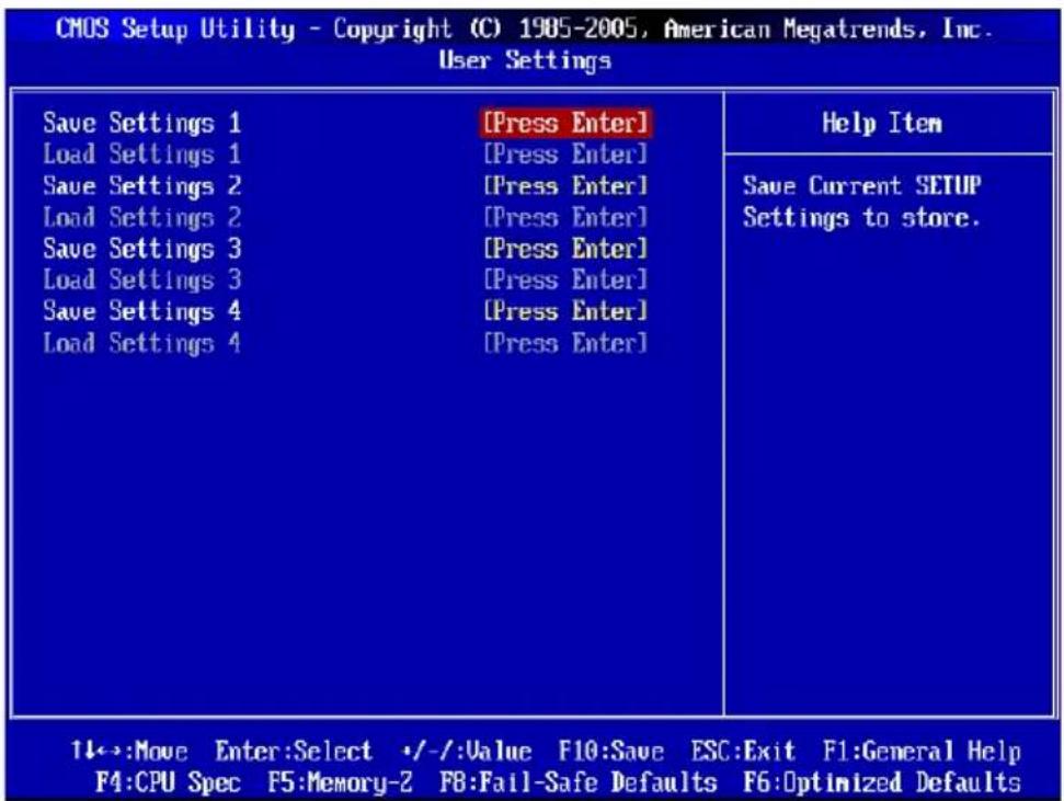
text_image
CMOS Setup Utility - Copyright (C) 1985-2005, American Megatrends, Inc. User Settings Save Settings 1 [Press Enter] Load Settings 1 [Press Enter] Save Settings 2 [Press Enter] Load Settings 2 [Press Enter] Save Settings 3 [Press Enter] Load Settings 3 [Press Enter] Save Settings 4 [Press Enter] Load Settings 4 [Press Enter] Help Item Save Current SETUP Settings to store. 1←→:Move Enter:Select +/-:Value F10:Save ESC:Exit F1:General Help F4:CPU Spec F5:Memory-2 F8:Fail-Safe Defaults F6:Optimized Defaults▶ Save Settings 1/2/3/4
These items are used to save the settings set by yourself to CMOS.
▶ Load Settings 1/2/3/4
These items are available after you save your settings in Save Settings 1/2/3/4 items, and are used to load the settings from CMOS.
LOAD FAIL-SAFE/ OPTIMIZED DEFAULTS
The two options on the main menu allow users to restore all of the BIOS settings to the default Fail-Safe or Optimized values. The Optimized Defaults are the default values set by the mainboard manufacturer specifically for optimal performance of the mainboard. The Fail-Safe Defaults are the default values set by the BIOS vendor for stable system performance.
When you select Load Fail-Safe Defaults, a message as below appears:

text_image
Load Failsafe Defaults? [Ok] [Cancel]Selecting Ok and pressing Enter loads the BIOS default values for the most stable, minimal system performance.
When you select Load Optimized Defaults, a message as below appears:

text_image
Load Optimal Defaults? [Ok] [Cancel]Selecting Ok and pressing Enter loads the default factory settings for optimal system performance.
Appendix A Realtek Audio
The Realtek audio provides 10-channel DAC that simultaneously supports 7.1 sound playback and 2 channels of independent stereo sound output (multiple streaming) through the Front-Out-Left and Front-Out-Right channels.
INSTALLING THE REALTEK HD AUDIO DRIVER
You need to install the HD audio driver for Realtek audio codec to function properly before you can get access to 2-, 4-, 6-, 8- channel or 7.1+2 channel audio operations. Follow the procedures described below to install the drivers for different operating systems.
Installation for Windows® XP
For Windows® XP, you must install Windows® XP Service Pack3 or later before installing the driver.
The following illustrations are based on Windows XP environment and could look slightly different if you install the drivers in different operating systems.
- Insert the application DVD into the DVD-ROM drive. The setup screen will automatically appear.
- Click Realtek HD Audio Drivers button.
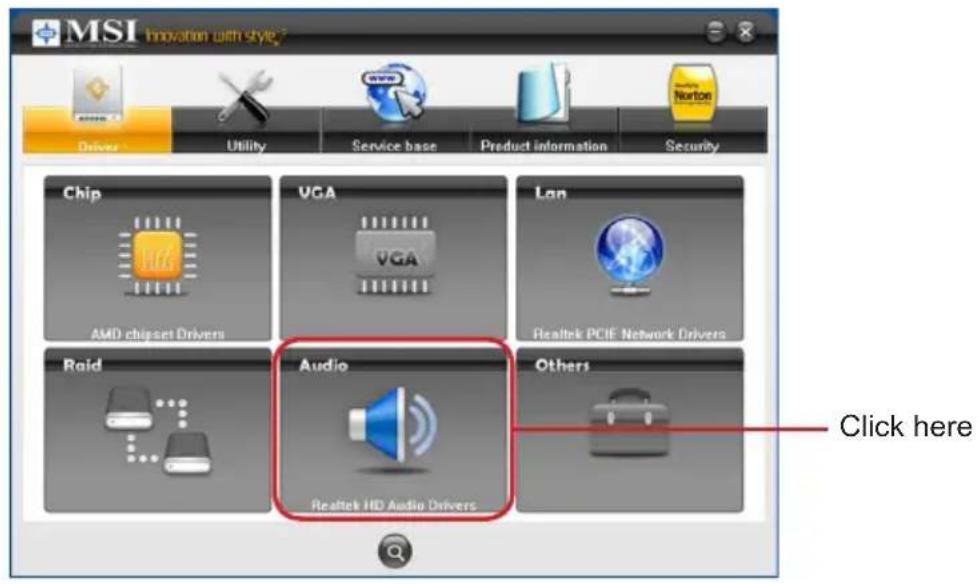
text_image
MSI Innovation with Style Driver Utility Service base Product information Security Chip VGA Lan AMD chipset Drivers VGA Realtek PCIE Network Drivers Raid Audio Realtek HD Audio Drivers Others Click hereImportant
The HD Audio Configuration software utility is under continuous update to enhance audio applications. Hence, the program screens shown here in this section may be slightly different from the latest software utility and shall be held for reference only.
Click Next to install the Realtek High Definition Audio Driver.3.
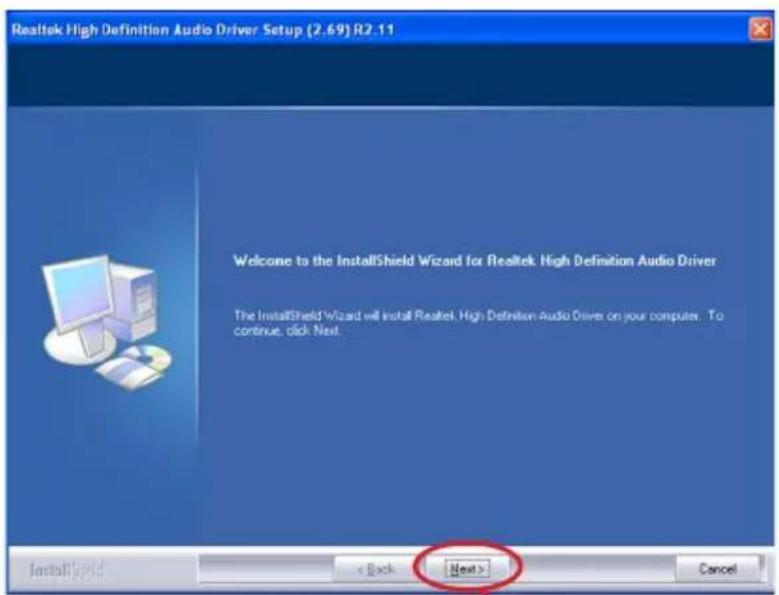
text_image
Realtek High Definition Audio Driver Setup (2.69) R2.11 Welcome to the InstallShield Wizard for Realtek High Definition Audio Driver The InstallShield Wizard will install Realtek High Definition Audio Driver on your computer. To continue, click Next. InstallShield < Back Next > CancelClick here
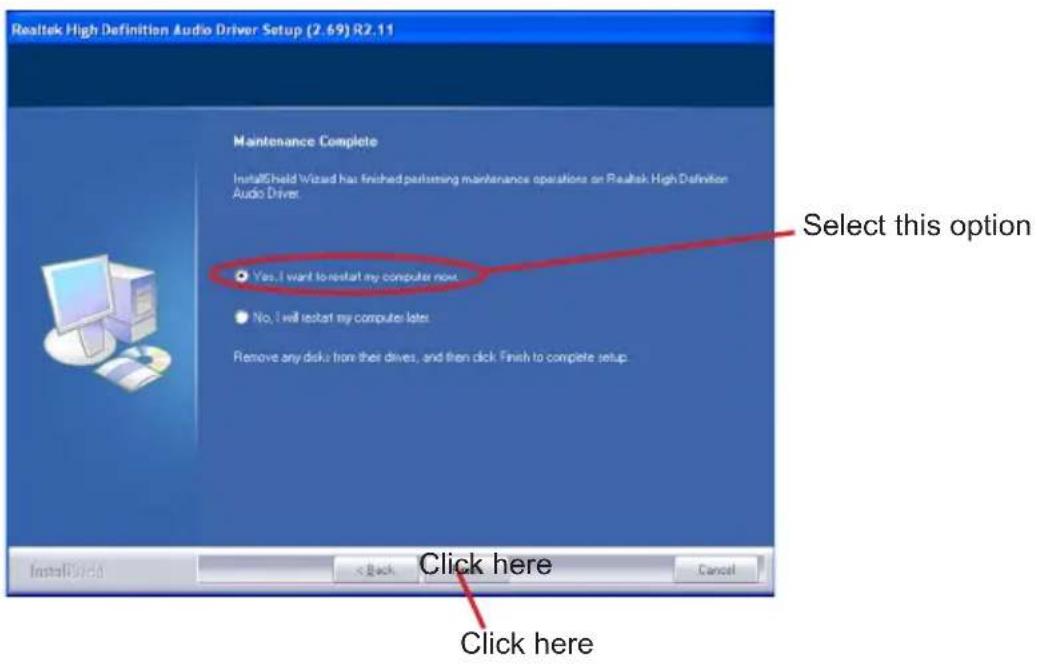
- Click Finish to restart the system.
text_image
Realtek High Definition Audio Driver Setup (2.69) R2.11 Maintenance Complete InstallShield Wizard has finished performing maintenance operations on Realtek High Definition Audio Driver. Yes, I want to restart my computer next. No, I will restart my computer next. Remove any disks from their drives, and then click Finish to complete setup. Select this option Click here Click hereSOFTWARE CONFIGURATION
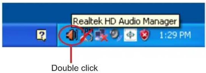
After installing the audio driver, you are able to use the 2-, 4-, 6- or 8- channel audio feature now. Click the audio icon from the system tray at the lower-right corner of the screen to activate the HD Audio Configuration. It is also available to enable the audio driver by clicking the Realtek HD Audio Manager from the Control Panel.
text_image
Realtek HD Audio Manager Double click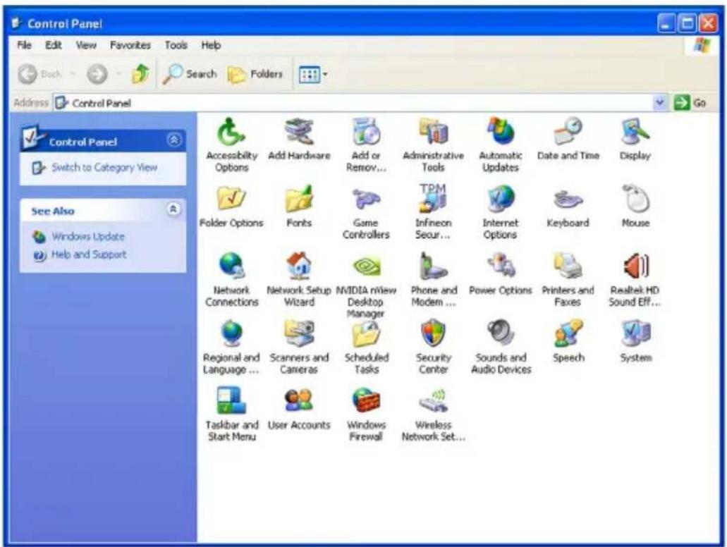
text_image
Control Panel File Edit View Favorites Tools Help Back Search Folders Address Control Panel Control Panel Switch to Category View See Also Windows Update Help and Support Accessibility Options Add Hardware Add or Remove... Administrative Tools Automatic Updates Date and Time Display Folder Options Fonts Game Controllers TPM Infineon Secur... Internet Options Keyboard Mouse Network Connections Network Setup Wizard NVIDIA nView Desktop Manager Phone and Modern ... Power Options Printers and Faxes Realtek HD Sound Eff... Regional and Language ... Scanners and Cameras Scheduled Tasks Security Center Sounds and Audio Devices Speech System Taskbar and Start Menu User Accounts Windows Firewall Wireless Network Set...Sound Effect
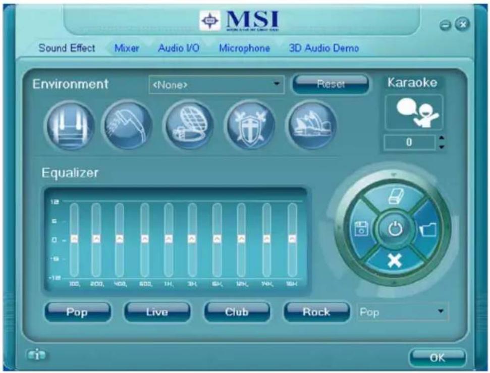
Here you can select a sound effect you like from the Environment list.
text_image
MSI Sound Effect Mixer Audio I/O Microphone 3D Audio Demo Environment■ Environment Simulation
You will be able to enjoy different sound experience by pulling down the arrow, totally 23 kinds of sound effect will be shown for selection. Realtek HD Audio Sound Manager also provides five popular settings "Stone Corridor", "Bathroom", "Sewer pipe", "Arena" and "Auditorium" for quick enjoyment.
You may choose the provided sound effects, and the equalizer will adjust automatically. If you like, you may also load an equalizer setting or make an new equalizer setting to save as an new one by using the "Load EQ Setting" and "Save Preset" button, click "Reset EQ Setting" button to use the default value, or click "Delete EQ Setting" button to remove a preset EQ setting.
There are also other pre-set equalizer models for you to choose by clicking “ Others” under the Equalizer part.
Realtek Audio
■ Equalizer Selection
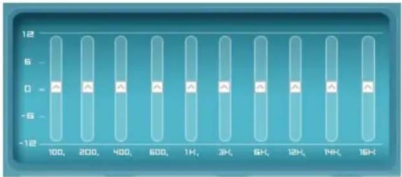
Equalizer frees users from default settings; users may create their owned preferred settings by utilizing this tool.
10 bands of equalizer, ranging from 100Hz to 16KHz.
bar
| X-Axis | Value | |---|---| | 100, | -5 | | 200, | -5 | | 400, | -5 | | 600, | -5 | | 1K, | -5 | | 3K, | -5 | | 6K, | -5 | | 12K, | -5 | | 14K, | -5 | | 16K, | -5 |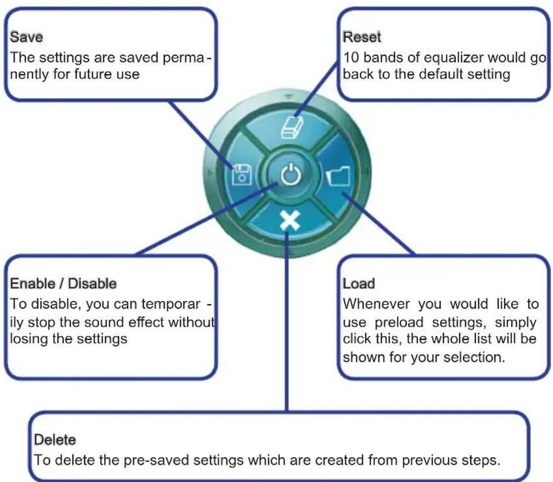
flowchart
graph TD
    A["Save\nThe settings are saved permanently for future use"] --> B["Reset\n10 bands of equalizer would go back to the default setting"]
    C["Enable / Disable\nTo disable, you can temporarily stop the sound effect without losing the settings"] --> B
    D["Load\nWhenever you would like to use preload settings, simply click this, the whole list will be shown for your selection."] --> B
    E["Delete\nTo delete the pre-saved settings which are created from previous steps."] --> B
Frequently Used Equalizer Setting
Realtek recognizes the needs that you might have. By leveraging our long experience at audio field, Realtek HD Audio Sound Manager provides you certain optimized equalizer settings that are frequently used for your quick enjoyment.
[How to Use It]
Other than the buttons "Pop", "Live", "Club" & "Rock" shown on the page, to pull down the arrow in "Others" you will find more optimized settings available to you.
■ Karaoke Mode
Karaoke mode brings Karaoke fun back home. Simply using the music you usually play, Karaoke mode can help you eliminate the vocal of the song or adjust the key to accommodate your range.
-
Vocal Cancellation: Single click on "Voice Cancellation" the vocal of the song would be eliminated, while the background music is still in place, and you can be that singer!
-
Key Adjustment: Using "Up / Down Arrow" to find a key which better fits your vocal range.
3.

text_image
Karaoke Remove the human voice 0 Raise the key Lower the keyRealtek Audio
Mixer
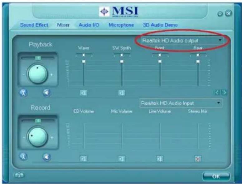
In the Mixer part, you may adjust the volumes of the rear and front panels individually.
■ Adjust Volume
You can adjust the volume of the speakers that you plugged in front or rear panel by select the Realtek HD Audio rear output or Realtek HD Audio front output items.
text_image
MSI Sound Effect Mixer Audio I/O Microphone 3D Audio Demo Playback Wave SW Synth Realtek HD Audio output Front Rear Record CD Volume Mic Volume Line Volume Stereo Mix Realtek HD Audio Input OKImportant
Before set up, please make sure the playback devices are well plugged in the jacks on the rear or front panel. The Realtek HD Audio front output item will appear after you plugging the speakers into the jacks on the front panel.
■ Multi-Stream Function
Realtek audio supports an outstanding feature called Multi-Stream, which means you may play different audio sources simultaneously and let them output respectively from the indicated real panel or front panel. This feature is very helpful when 2 people are using the same computer together for different purposes.
Click the 📁 button and the Mixer ToolBox menu will appear. Then check the Enable playback multi-streaming and click OK to save the setup.
Important
You have to plug audio device into the jacks on the rear and front panel first before enable the multi-stream function.
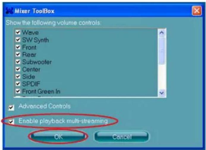
text_image
Mixer ToolBox Show the following volume controls: ✓ Wave ✓ SW Synth ✓ Front ✓ Rear ✓ Subwoofer ✓ Center ✓ Side ✓ SPDIF ✓ Front Green In ✓ Advanced Controls ✓ Enable playback multi-streaming OK CancelWhen you are playing the first audio source (for example: use Windows Media Player to play DVD/VCD), the output will be played from the rear panel, which is the default setting.
Then you must to select the Realtek HD Audio 2nd output from the scroll list first, and use a different program to play the second audio source (for example: use Winamp to play MP3 files). You will find that the second audio source (MP3 music) will come out from the Line-Out audio jack of Front Panel.
text_image
MSI Sound Effect Mixer Audio I/O Microphone 3D Audio Demo Playback Wave SW Sync Record CD Volume Mic Volume Line Volume Stereo Mix Riealtek HD Audio output Riealtek HD Audio output Riealtek HD Audio 2nd output Riealtek HD Audio Input OKRealtek Audio
■ Playback control
text_image
MSI Sound Effect Mixer Audio I/O Microphone 3D Audio Demo Playback Wave 5W Synth Realtek HD Audio output Tool Mute Playback deviceThis function is to let you freely decide which ports to output the sound. And this is essential when multi-streaming playback enabled.
- Realtek HD Audio Rear Output
- Realtek HD Audio Front Output
Mute
You may choose to mute single or multiple volume controls or to completely mute sound output.
Tool
- Show the following volume controls
This is to let you freely decide which volume control items to be displayed.
- Advanced controls
- Enable playback multi-streaming
With this function, you will be able to have an audio chat with your friends via headphone (stream 1 from front panel) while still has music (stream 2 from back panel) in play. At any given period, you can have maximum 2 streams operating simultaneously.
text_image
Mixer Toolbox Show the following volume controls: ✓ Wave ✓ SW Synth ✓ Front ✓ Rear ✓ Subwoofer ✓ Center ✓ Side ✓ SPDIF ✓ Front Green In ✓ Advanced Controls ✓ Enable playback multi-streaming OK Cancel■ Recording control
text_image
Record CD Volume Mic Volume Line Volume S stereo Mix Tool Mute Realtek HD Audio Input Recording device -Back Line in/ Mic, Front Lin in -Realtek HD Audio InputMute
You may choose to mute single or multiple volume controls or to completely mute sound input.
Tool
- Show the following volume controls
This is to let you freely decide which volume control items to be displayed.
- Enable recording multi-streaming
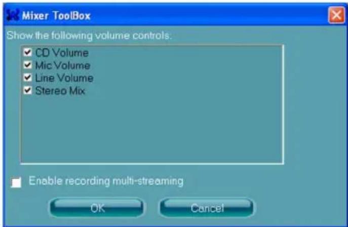
text_image
Mixer Toolbox Show the following volume controls: ✓ CD Volume ✓ Mic Volume ✓ Line Volume ✓ Stereo Mix Enable recording multi-streaming OK CancelImportant
Realtek audio allows you to record the CD, Line, Mic and Stereo Mix channels simultaneously, frees you from mixing efforts. At any given period, you may choose 1 of the following 4 channels to record.
Audio I/O
In this tab, you can easily configure your multi-channel audio function and speakers. You can choose a desired multi-channel operation here.
■ Headphone for the common headphone
■ 2CH Speaker for Stereo-Speaker Output
■ 4CH Speaker for 4-Speaker Output
■ 6CH Speaker for 5.1-Speaker Output
■ 8CH Speaker for 7.1-Speaker Output
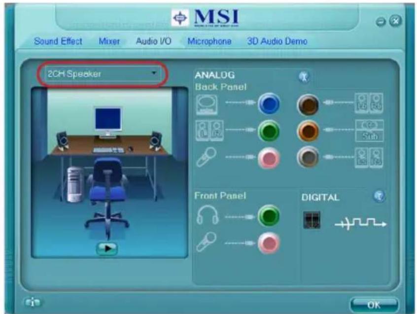
text_image
MSI Sound Effect Mixer Audio I/O Microphone 3D Audio Demo 2CH Speaker ANALOG Back Panel Front Panel DIGITAL OK■ Speaker Configuration:
- Plug the speakers in the corresponding jack.
- Dialogue "connected device" will pop up for your selection. Please select the device you have plugged in.
- If the device is being plugged into the correct jack, you will be able to find the icon beside the jack changed to the one that is same as your device.
- If not correct, Realtek HD Audio Manager will guide you to plug the device into the correct jack.
■ Connector Settings
Click to access connector settings.
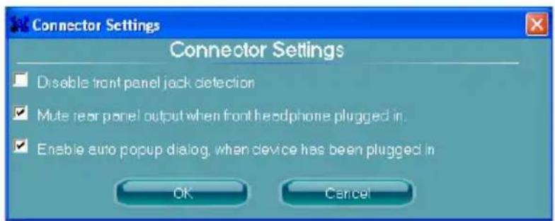
text_image
Connector Settings Connector Settings Disable front panel jack detection Mute rear panel output when front headphone plugged in. Enable auto popup dialog, when device has been plugged in OK CancelDisable front panel jack detection (optional)
Jack detection function only works with HD audio front panel. Please check if front jacks on your system are so-called AC'97 jacks. If so, please check this item to disable front panel jack detection.
Mute rear panel output when front headphone plugged in.
Enable auto popup dialogue, when device has been plugged in
Once this item checked, the dialog "Connected device" would automatically pop up when device plugged in.
Realtek Audio
■ S/PDIF
Short for Sony/Philips Digital Interface, a standard audio file transfer format. S/PDIF allows the transfer of digital audio signals from one device to another without having to be converted first to an analog format. Maintaining the viability of a digital signal prevents the quality of the signal from degrading when it is converted to analog.
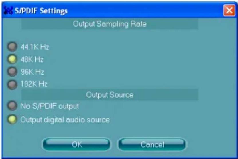
text_image
S/PDIF Settings Output Sampling Rate 44.1K Hz 48K Hz 96K Hz 192K Hz Output Source No S/PDIF output Output digital audio source OK CancelOutput Sampling Rate
44.1KHz: This is recommend while playing CD.
48KHz: This is recommended while playing DVD or Dolby.
96KHz: This is recommended while playing DVD-Audio.
192KHz: This is recommended while playing High quality Audio.
Output Source
Output digital audio source: The digital audio format (such as .wav, .mp3,.midi etc) will come out through S/PDIF-Out.
S/PDIF-in to S/PDIF -out pass though mode: The data from S/PDIF-In can be real-time played from S/PDIF-Out.
■ Test Speakers
You can select the speaker by clicking it to test its functionality. The one you select will light up and make testing sound. If any speaker fails to make sound, then check whether the cable is inserted firmly to the connector or replace the bad speakers with good ones. Or you may click the auto test button to test the sounds of each speaker automatically.
text_image
Center Front Left Front Right Side Left Side Right Subwoofer Rear Left Rear RightRealtek Audio
Microphone
In this tab you may set the function of the microphone. Select the Noise Suppression to remove the possible noise during recording, or select Acoustic Echo Cancellation to cancel the acoustic echo during recording.
Acoustic Echo Cancellation prevents playback sound from being recorded by micro phone together with your sound. For example, you might have chance to use VOIP function through Internet with your friends. The voice of your friend will come out from speakers (playback). However, the voice of your friend might also be recorded into your microphone then go back to your friend through Internet. In that case, your friend will hear his/her own voice again. With AEC (Acoustic Echo Cancellation) enabled at your side, your friend can enjoy the benefit with less echo.
text_image
MSI Sound Effect Mixer Audio I/O Microphones 3D Audio Demo Noise Suppression Acoustic Echo Cancellation OK3D Audio Demo
In this tab you may adjust your 3D positional audio before playing 3D audio applications like gaming. You may also select different environment to choose the most suitable environment you like.
text_image
MSI Sound Effect Vixer Audio I/O Microphone 3D Audio Demo Sound : Loopy Music Buzzing Bee Moving Path : Horizontal Vertical Insect Motion Manual - Horizontal Manual - Vertical Environment :Realtek Audio
Information
In this tab it provides some information about this HD Audio Configuration utility, including Audio Driver Version, DirectX Version, Audio Controller & Audio Codec. You may also select the language of this utility by choosing from the Language list.
text_image
Information i information Audio Driver Version : 5.10.0.5755 DirectX Version : DirectX 9.0 Audio Controller : HD Audio Audio Codec : ALC888S Language : Auto Show icon in system tray OKAlso there is a selection Show icon in system tray. Switch it on and an icon will show in the system tray. Right-click on the icon and the Audio Accessories dialogue box will appear which provides several multimedia features for you to take advantage of.
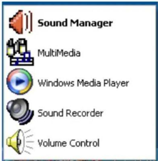
text_image
Sound Manager MultiMedia Windows Media Player Sound Recorder Volume ControlHARDWARE SETUP
Connecting the Speakers
When you have set the Multi-Channel Audio Function mode properly in the software utility, connect your speakers to the correct phone jacks in accordance with the setting in software utility.
■ 2-Channel Mode for Stereo-Speaker Output
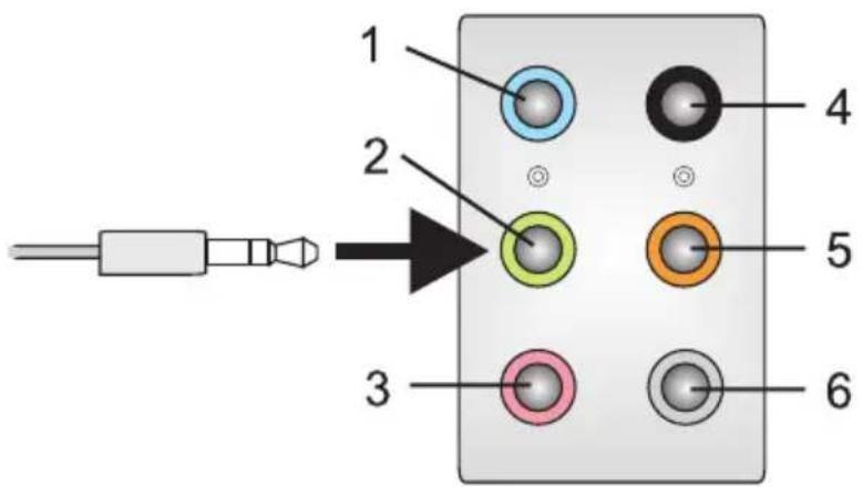
text_image
1 2 3 4 5 61] Line In
2] Line Out (Front channels)
3] MIC
4] No function
5] No function
6] No function
Realtek Audio
■ 4-Channel Mode for Stereo-Speaker Output

text_image
1 2 3 4 5 61] Line In
2] Line Out (Front channels)
3] MIC
4] Line Out (Rear channels)
5] No function
6] No function
■ 6-Channel Mode for Stereo-Speaker Output
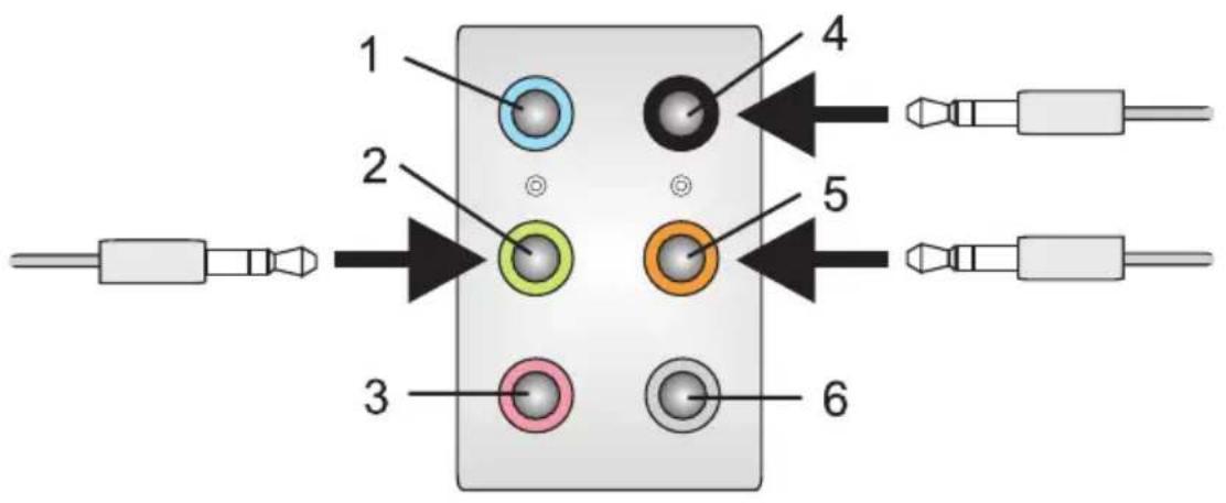
text_image
1 2 3 4 5 61] Line In
2] Line Out (Front channels)
3] MIC
4] Line Out (Rear channels)
5] Line Out (Center and Subwoofer channel)
6] No function
Realtek Audio
■ 8-Channel Mode for Stereo-Speaker Output
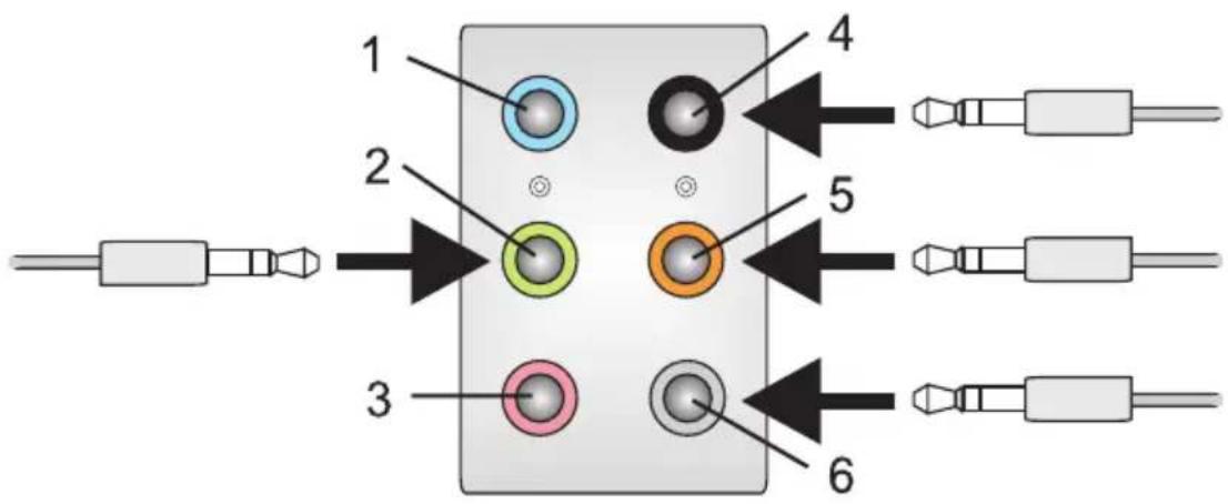
text_image
1 2 3 4 5 61] Line In
2] Line Out (Front channels)
3] MIC
4] Line Out (Rear channels)
5] Line Out (Center and Subwoofer channel)
6] Line Out (Side channels)
Important
To enable 7.1 channel audio-out function on Windows Vista operating system, you have to install the Realtek Audio Driver. Or, the mainboard will support 5.1 channel audio-out only.
The integrated one SATA host controller separately, and support RAID function for performance and reliability. SB710 SATA RAID (SATA1\~5) provides support for RAID 0 (Striping), RAID 1 (Mirroring) & RAID 10 (Striping & Mirroring). RAID 0 greatly improves hard disk I/O performance by concurrently striping data across multiple drives. RAID 1 makes sure data is not lost if a drive fails as data is simultaneously written to two drives. Drives configured for RAID Striping are said to form a RAID 0 set, while drives configured for RAID Mirroring are said to form a RAID 1 set. RAID 10 is implemented as a mirrored array whose segments are RAID 0 arrays. RAID 10 has same fault tolerance as mirroring and reduces overhead by striping. It needs at least four drives to form a RAID 10.
RAID CONFIGURATION
Creating and deleting RAID set and performing other RAID setting up operations are done in the RAID BIOS. During boot-up, a screen similar to the one below will appear for about few seconds. Press
No Array is defined...
Press
Important
Be sure to enable the RAID function for SATA device in BIOS before configuring the Fastbuild Utility.
The FastBuild menu screen will appear. The Main Menu is used to choose the operation to be performed.
text_image
[ Main Menu ] View Drive Assignments......[ 1 ] Define LD......[ 2 ] Delete LD......[ 3 ] Controller Configuration......[ 4 ] [ Keys Available ] Press 1...4 to Select Option [ ESC ] ExitView Drives Assignments
This window displays the model number, capacities and assignment of the drives physically attached to the SATA host adapter.
text_image
[ View Drives Assignments ] Channel : ID Drive Model Capacity (MB) Assignment 1 : Mas WDC WD800JD-00HKA0 80027 Extent 1 79960 Free 2 : Mas WDC WD800JD-00HKA0 80027 Extent 1 79960 Free [ Keys Available ] [ ↑ ] Up [ ↓ ] Down [ ESC ] ExitDefine LD (Creating RAID)
The selection of the RAID configuration should be based upon factors including performance, data security, and the number of drives available. It is best to carefully consider the long-term role of the system and plan the data storage strategy. RAID sets can be created either automatically, or to allow the greatest flexibility, manually.
- Press 2 on the Main Menu screen to enter the Define LD Menu.
- Press the arrow keys to highlight a logical drive number you want to define and press Enter to select it.
text_image
[ Define LD Menu ] LD No RAID Mode Total Drv Capacity (MB) Status LD 1 ---- ---- ---- ---- LD 2 ---- ---- ---- ---- LD 3 ---- ---- ---- ---- LD 4 ---- ---- ---- ---- LD 5 ---- ---- ---- ---- LD 6 ---- ---- ---- ---- LD 7 ---- ---- ---- ---- LD 8 ---- ---- ---- ---- [ Keys Available ] [↑] Up [↓] Down [ESC] Exit [Enter] Select- On the next screen, use the space key to choose a RAID mode (RAID 0/1/10) and use the arrow key to move to the "Drives Assignments" window.
text_image
[ Define LD Menu ] LD No RAID Mode Total Drv LD 1 RAID 1 2 Stripe Block : NA Fsat Init: OFF Gigabyte Boundary : ON Cache Mode : WriteThru [ Drives Assignments ] Channel: ID Drive Model Capacity (MB) Assignment 1: Mas WDC WD800JD-00HKA0 80027 N 2: Mas WDC WD800JD-00HKA0 80027 N [ Keys Available ] [↑] Up [↓] Down [ESC] Exit [Space] Change Option [Ctrl-Y] Save■ Initialize logical drive, zero the disk drives. RAID 1 or 10 only.
■ Stripe Block Size, the default 64KB is best for most applications. RAID 0 or 10 only.
■ Gigabyte Boundary, allows use of slightly smaller replacement drives.
■ Cache Mode, WriteThru or WriteBack.
- On the Drives Assignments window, use the arrow key to choose the hard drives which you want to make part of the LD, use the space key to change the assignment to "Y". Then press [Ctrl+Y] to save the configuration.
text_image
[ Define LD Menu ] LD No RAID Mode Total Drv LD 1 RAID 1 2 Stripe Block : NA Fsat Init : OFF Gigabyte Boundary : ON Cache Mode : WriteThru [ Drives Assignments ] Channel : ID Drive Model Capacity (MB) Assignment 1 : Mas WDC WD800JD-00HKA0 80027 Y 2 : Mas WDC WD800JD-00HKA0 80027 Y [ Keys Available ] [↑] Up [↓] Down [ESC] Exit [Space] Change Option [Ctrl-Y] Save- A message will show up on the bottom, press any key to save the configuration or press [Ctrl-Y] to allocate the RAID capacity manually.

text_image
Press Ctrl -Y to Modify Array Capacity or press any other key to use maximum capacity...Important
• The default capacity is the full capacity of the selected hard drives.
- If you allocate the first LD capacity manually, you can create second LD with remaining capacity of the selected hard drives.
- The LD creation is done, the screen shows the LD information as below. Press ESC key to the main screen.
text_image
[Define LD Menu] LD No RAID Mode Total Drv Capacity (MB) Status LD 1 RAID 1 2 79000 Functional LD 2 ----- ----- ----- ----- LD 3 ----- ----- ----- ----- LD 4 ----- ----- ----- ----- LD 5 ----- ----- ----- ----- LD 6 ----- ----- ----- ----- LD 7 ----- ----- ----- ----- LD 8 ----- ----- ----- ----- [Keys Available ] [↑] Up [↓] Down [ESC] Exit [Enter] Select- Press ESC key to exit the utility, a message "System is going to REBOOT! Are You Sure?" will display, answer "Y" to exit it and the system will reboot.

text_image
[ Main Menu ] View Drive Assignments......[ 1 ] Define LD......[ 2 ] Delete LD......[ 3 ] Con System is going to REBOOT! Are You Sure ? Y - Reboot / Any Key - Back [ Keys Available ] Press 1..4 to Select Option [ ESC ] ExitDelete LD (Deleting RAID)
- Select "Delete LD" on the main screen.
- Choose a LD No you want to delete and press "Del" or "Alt+D" delete the RAID set.
text_image
[ Define LD Menu ] LD No RAID Mode Total Drv Capacity (MB) Status LD 1 RAID 1 2 79000 Functional LD 2 ---- ---- ---- ---- LD 3 ---- ---- ---- ---- LD 4 ---- ---- ---- ---- LD 5 ---- ---- ---- ---- LD 6 ---- ---- ---- ---- LD 7 ---- ---- ---- ---- LD 8 ---- ---- ---- ---- [ Keys Available ] [↑] Up [↓] Down [ESC] Exit [Enter] Select- On the next screen, a message will display to inform you, press "Ctrl+Y" to delete the RAID set or other key to abort it. Press "Ctrl+Y" to complete the deletion.
text_image
[Define LD Menu] LD No RAID Mode Total Drv Capacity (MB) Status LD 1 RAID 1 2 79000 Functional Stripe Block : NA Cache Mode : WriteThru [Drives Assignments] Channel: ID Drive Model Capacity (MB) 1 : Mas WDC WD800JD-00HKA0 80027 2 : Mas WDC WD800JD-00HKA0 80027 Ctrl-Y to delete the ARRAY and MBR, Ctrl-F to delete the ARRAY only, other key to abortInstalling the RAID Driver (for bootable RAID Array)
- After you complete the RAID BIOS setup, boot from the Windows CD, and the Windows Setup program starts.
- Press F6 and wait for the Windows Setup screen to appear.
- Insert the floppy that contains the RAID driver, press the "S" key to select "Specify Additional Device".
Note: for Windows Vista, you can copy the files to a medium (floppy/ CD/ DVD or USB)
Important
Please follow the instruction below to make a SATA RAID driver for yourself.
- Insert the MSI DVD into the DVD-ROM drive.
- Click the "Browse DVD" on the Setup screen.
• Copy all the contents in the : - for Windows XP: |ChipSet\AMD\XP\SBDrv\RAID7xx
- for Windows Vista: \ChipSet\AMD\VISTA\Packages\Drivers\SBDrv\SB7xx\RAID\x86 (for 32bit) or x64(for 64bit)
• The driver disk for RAID controller is done.
- When prompted, insert the floppy disk and press Enter.
For Windows Vista:
During the Operating system installation, after selecting the location to install Vista click on "Load Driver" button to load RAID drive.
- You should be shown a list of available SCSI Adapters.
- Select the compatible RAID controller for 32-bit/64-bit version system and then press ENTER.
- The next screen should confirm that you have selected the RAID controller. Press ENTER again to continue.
- You have successfully installed the RAID driver, and Windows setup should continue.
- Leave the disk in the floppy drive until the system reboots itself. Windows setup will need to copy the files from the floppy again after the RAID volume is formatted, and Windows setup starts copying files.
Installing the RAID Driver Under Windows (for Non-bootable RAID Array)
- Insert the MSI DVD into the DVD-ROM drive.
- The DVD will auto-run and the setup screen will appear.
- Under the Driver tab, click on AMD chipset drivers by your need. The AMD chipset drivers include RAID Driver.
- The driver will be automatically installed.
Appendix C Overclocking Center
Overclocking Center, the most useful and powerful utility that MSI has spent much research and efforts to develop, helps users to monitor or configure the hardware status of MSI Mainboard in windows, such as CPU clock, voltage, fan speed and temperature.
Before you install the Overclocking Center, please make sure the system has meet the following requirements:
- 256MB system memory.
- DVD-ROM drive for software installation.
- Operation system: Windows XP or up.
- DotNet Frame Work 2.0
Activating Overclocking Center
Once you have your Overclocking Center installed (locate the setup source file in the setup DVD accompanying with your mainboard, path: Utility --> MSI Utility --> Overclocking Center), it will have a short cut icon on the desktop, and a short cut path in your "Start-up" menu. You may double-click on each icon to activate Overclocking Center.
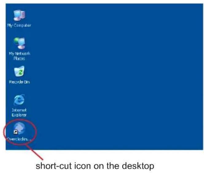
text_image
My Computer My Network Places Recycle Bin Internet Explorer Overclock short-cut icon on the desktop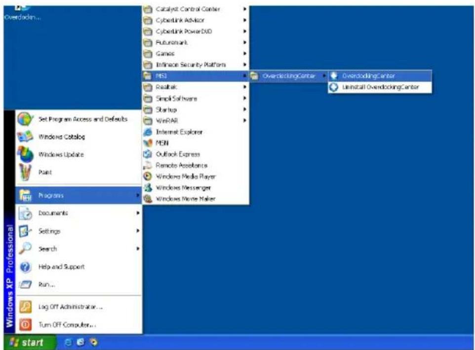
text_image
Overdoding... Catalyst Control Center CyberLink Advisor CyberLink Power DVD Futuremark Games Infineon Security Platform MSI OverdodingCenter OverdodingCenter Uninstall OverdodingCenter ReadLab Simple Software Startup WinRAR Internet Explorer MEN Outlook Express Remote Accessories Windows Media Player Windows Messenger Windows Movie Maker Set Program Access and Defaults Windows Catalog Windows Update Paint Programs Documents Settings Search Help and Support Run... Log Off Administrator ... Turn Off Computer... start Windows XP Professionalshort-cut path in the start-up menu
(path: Start-->Program Files-->MSI-->Overclocking Center-->Overclocking Center)
SYSTEM INFO
In the System Info screen, you can read the information of motherboard/ memory/ PCI.
Motherboard
Click Motherboard to read the information of motherboard, BIOS, installed CPU and installed graphics card.
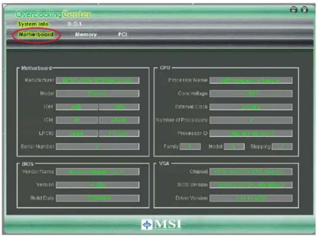
text_image
Overclocking Center System Info D.O.T. Motherboard Memory PCI Motherboard Manufacturer WSS/SISI (MISI/SISI) Model VACOS IOH AII CIVS ICH AP LIF/SI LPCIC Serial P1000 Serial Number 2 CPU Processor Name SWE-SW/MSI/SISI Cora Voltage VAC External Clock VACOS Number of Processors 1 Processor ID Select for Power Family Model Slipping BIOS Vendor Name Applicable Version VAC Build Data Access VGA Chipset SWE-SP/MSI/SISI/SISI BIOS Version Select for Power Driver Version 2.5 to 450 MSIImportant
The pictures in this appendix are for reference only and may vary from the product you purchased. Please refer to the appearance of your system for detailed information.
Memory
Click Memory to read the information of each memory DIMM slot. You can select a DIMM slot you want to read from the SPD list.
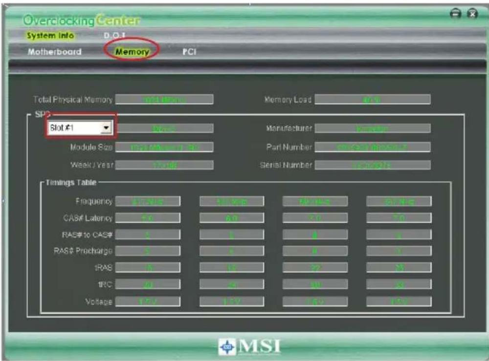
text_image
Overclocking Center System info D.O.T Motherboard Memory PCI Total Physical Memory Total Users Memory Load 4.0 SPD Slot #1 Raw Manufacturer Manager Module Size 102/AMR/30 Part Number 0.0000000000 Week/Year 7-10 Serial Number sample Timings Table Frequency 5.0V 3.0V 6.0V 10.0V CAS# Latency 5.0 6.0 7.0 RAS# to CAS# 5 1 4 5 RAS# Procharge 5 1 1 1 IRAS 5 10 22 5 1RC 20 8 90 8 Voltage 12V 12V 14V 15V MSIPCI
Click PCI to read the information of devices on the mainboard.
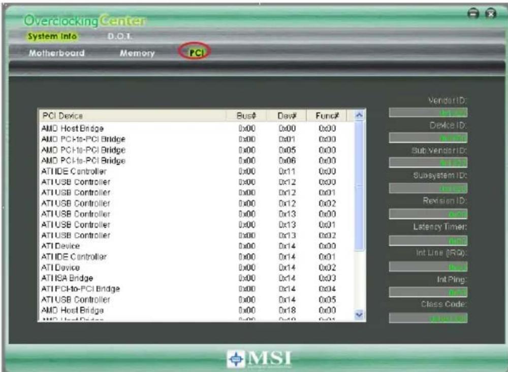
text_image
Overclocking Center System Info D.O.T. Motherboard Memory PCI PCI Device Bus# Dev# Func# AMD Host Bridge 0x00 0x00 0x00 AMD PCI-to-PCI Bridge 0x00 0x01 0x00 AMD PCI-to-PCI Bridge 0x00 0x05 0x00 AMD PCI-to-PCI Bridge 0x00 0x06 0x00 ATIIDE Controller 0x00 0x11 0x00 ATIUSB Controller 0x00 0x12 0x00 ATIUSB Controller 0x00 0x12 0x01 ATIUSB Controller 0x00 0x12 0x02 ATIUSB Controller 0x00 0x13 0x00 ATIUSB Controller 0x00 0x13 0x01 ATIUSB Controller 0x00 0x13 0x02 ATIDevice 0x00 0x14 0x00 ATIIDE Controller 0x00 0x14 0x01 ATIDevice 0x00 0x14 0x02 ATISA Bridge 0x00 0x14 0x03 ATIPCI-to-PCI Bridge 0x00 0x14 0x04 ATIUSB Controller 0x00 0x14 0x05 AMD Host Bridge 0x00 0x18 0x00 AMD Host Bridge 0x00 0x19 0x01 Vendor ID: Device ID: Sub Vendor ID: Subsystem ID: Revision ID: Latency Timer: Int Line (R/D): Int Ping: Class Code:DOT
Click DOT to enter the DOT screen. In DOT, you can select the basic setting to reach optimal performance in Novice menu or you can adjust advanced values for overclocking in Advance menu.
Novice
In the Novice menu, it provides one default setting and several common settings for different environments. You may choose one of the settings that you need. The settings in Novice menu are not adjustable.
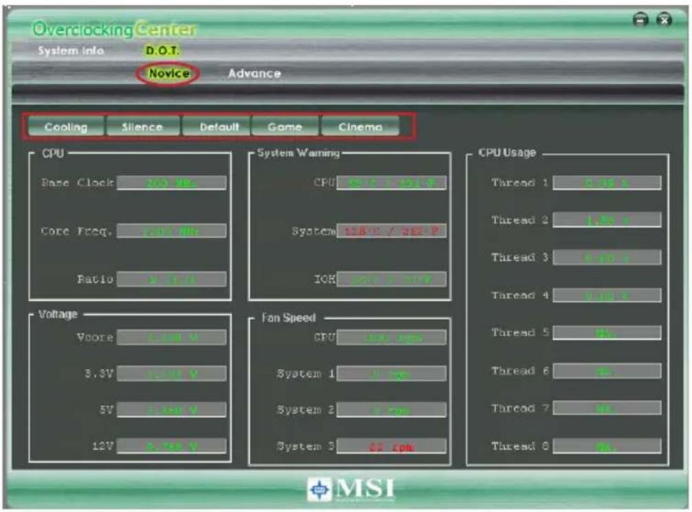
text_image
Overclocking Center System Info D.O.T. Novice Advance Cooling Silence Default Game Cinema CPU Base Clock 200 Hz Core Freq. 100 Hz Ratio 5.0 Hz System Warning CPU 128 V / 362 P System 128 V / 362 P ICR 128 V / 362 P Voltage Voore 2.00 V 3.3V 1.00 V 5V 1.00 V 12V 1.00 V Fan Speed CPU 128 V / 362 P System 1 1.00 V System 2 1.00 V System 3 32.00 V CPU Usage Thread 1 1.00 V Thread 2 1.00 V Thread 3 1.00 V Thread 4 1.00 V Thread 5 1.00 V Thread 6 1.00 V Thread 7 1.00 V Thread 8 1.00 V MSIImportant
You may change the values of each environment setting/ default setting in Advance menu. Please refer the following section for more details.
Overclocking Center
Advance
In the Advance menu, you can adjust the values for each environment setting/ default setting. Click the Cooling/ Silence/ Default/ Game/ Cinema button to enter it's setting menu. Please refer to the following descriptions to adjust the values and save them.
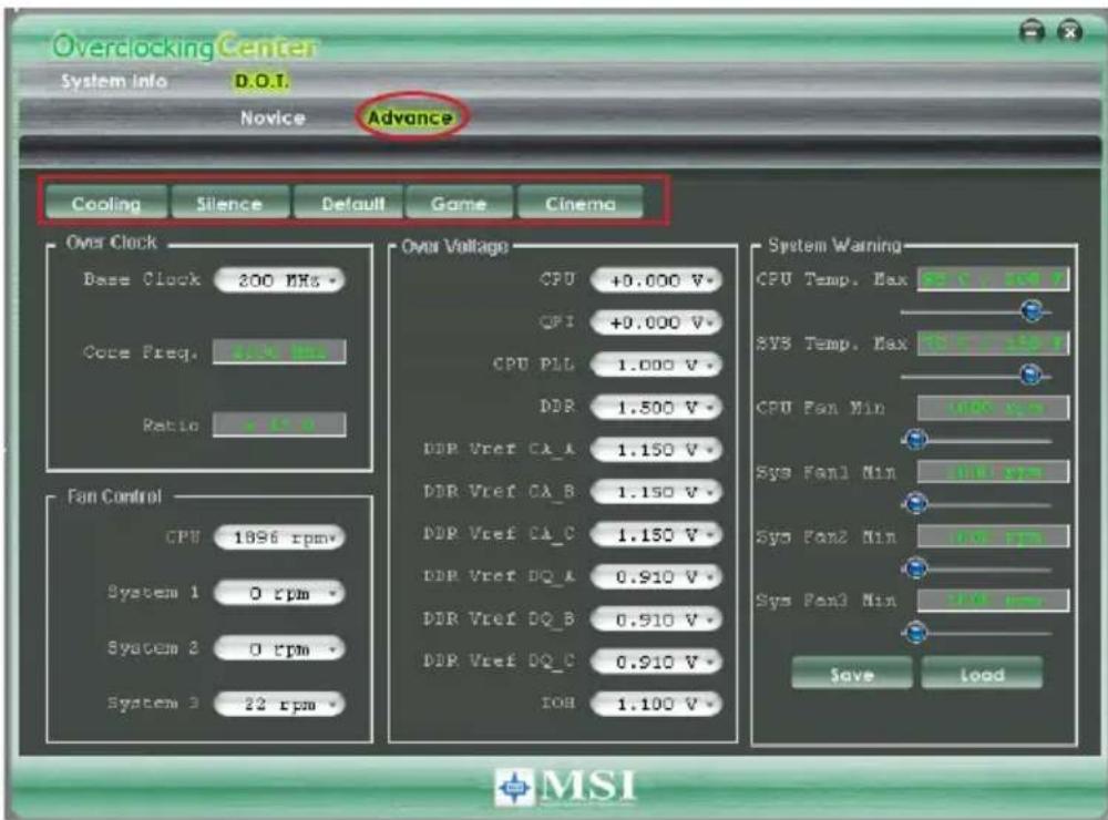
text_image
Overclocking Center System info D.O.T. Novice Advance Cooling Silence Default Game Cinema Over Clock Base Clock 200 MHz Cock Preq. 500 MHz Ratio >10 % Fan Control CPU 1896 rpm* System 1 0 rpm* System 2 0 rpm* System 3 22 rpm Over Voltage CPU +0.000 V* CFI +0.000 V* CPU PLL 1.000 V* DDR 1.500 V* DDR Vref CA_A 1.150 V* DDR Vref CA_B 1.150 V* DDR Vref CA_C 1.150 V* DDR Vref DQ_A 0.910 V* DDR Vref DQ_B 0.910 V* DDR Vref DQ_C 0.910 V* IOB 1.100 V System Warning CPU Temp. Max F: 5 V, 50 V SYS Temp. Max F: 7 V, 5 V CPU Fan Min 10V rpm Sys Fan1 Min 10V rpm Sys Fan2 Min 10V rpm Sys Fan3 Min 10V rpm Save Load MSIIn each setting menu, you can select desired values for manual overclocking. Simply click the right side of the button which arranges an arrow sign, and a drop-down menu will appear below the button, then select a value.
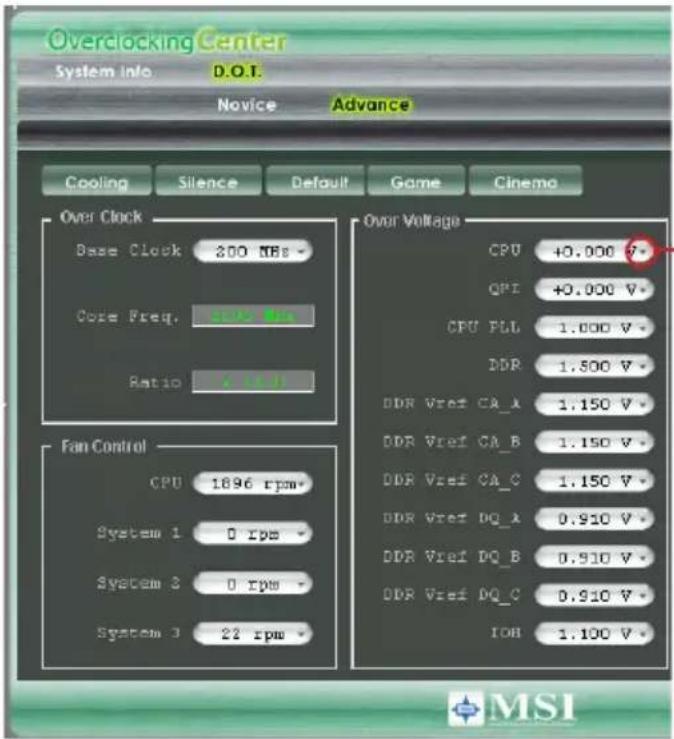
text_image
Overclocking Center System info D.O.T. Novice Advance Cooling Silence Default Game Cinema Over Clock Base Clock 200 NEs - Core Freq. 1000 Hz Ratio 1.5 V Fan Control CPU 1896 rpm- System 1 0 rpm- System 2 0 rpm- System 3 22 rpm Over Voltage CPU +0.000 V* QPI +0.000 V* CPU PLL 1.000 V* DDR 1.500 V* DDR Vref CA_A 1.150 V* DDR Vref CA_B 1.150 V* DDR Vref CA_C 1.150 V* DDR Vref DQ_A 0.910 V* DDR Vref DQ_B 0.910 V* DDR Vref DQ_C 0.910 V* IOB 1.100 V MSIClick the arrow sign and the drop-down menu will appear.
In the "System Warning" block, you can set the maximum CPU/ system temperature and the minimum CPU/ system fan speed by using the scroll bar. The system will pop-up a warning message to warning you when the temperature/ fan speed is over/ lower the values you set.
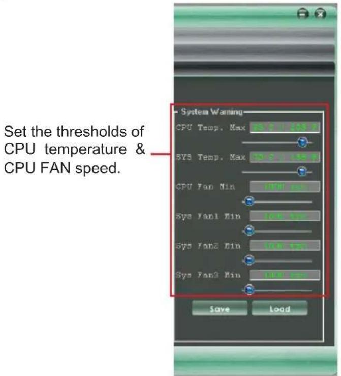
text_image
Set the thresholds of CPU temperature & CPU FAN speed. System Warning CPU Temp. Max 12.0 13.0 SYS Temp. Max 12.0 13.0 CPU Fan Min 17.0 Hz Sys Fan1 Min 16.0 Hz Sys Fan2 Min 15.0 Hz Sys Fan3 Min 14.0 Hz Save LoadOverclocking Center
After you adjust the values in setting menu, you can save it for future use.
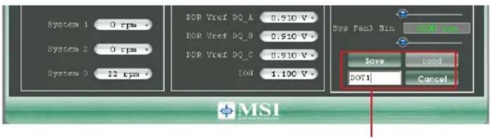
Click the Save button, and enter a name in the empty box. Then, click Save button again to save the settings.
Important
It provides you to save up to 20 user settings.
Click the Load button and choose a saved user setting to load the settings for the system.
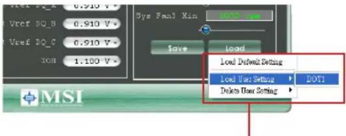
text_image
Vref DQ_B 0.910 V Vref DQ_C 0.910 V IOB 1.100 V Sys Fan3 Min Save Load Load Default Setting Load User Setting DOT1 Delete User Setting MSIClick the Load button, and choose a saved user setting.
Important
Every time you turn-off the system, the settings will be restored to the factory default. If you want to use the saved settings, you have to load it after entering the operating system every time.