PH61-P33 - Motherboard MSI - Free user manual and instructions
Find the device manual for free PH61-P33 MSI in PDF.

User questions about PH61-P33 MSI
0 question about this device. Answer the ones you know or ask your own.
Ask a new question about this device
Download the instructions for your Motherboard in PDF format for free! Find your manual PH61-P33 - MSI and take your electronic device back in hand. On this page are published all the documents necessary for the use of your device. PH61-P33 by MSI.
USER MANUAL PH61-P33 MSI
text_image
Digital graphic with binary code overlay and a stylized bar chart, likely representing a financial or business concept.
natural_image
Abstract digital globe with glowing rings and abstract light effects, no visible text or symbolsmsi™
PH61A-P35 (B3)/
PH61-P33 (B3)/
PH61-SP35 (B3)
series
MS-7732 (v1.x) Mainboard
Copyright Notice
The material in this document is the intellectual property of MICRO-STAR INTERNATIONAL. We take every care in the preparation of this document, but no guarantee is given as to the correctness of its contents. Our products are under continual improvement and we reserve the right to make changes without notice.
Trademarks
All trademarks in this manual are properties of their respective owners.
■ MSI ^® is registered trademark of Micro-Star Int'l Co., Ltd.
■ NVIDIA® is registered trademark of NVIDIA Corporation.
■ ATI ^® is registered trademark of AMD Corporation.
■ AMD® is registered trademarks of AMD Corporation.
Intel® is registered trademarks of Intel Corporation.
■ Windows® is registered trademarks of Microsoft Corporation.
■ AMI® is registered trademark of American Megatrends Inc.
■ Award® is a registered trademark of Phoenix Technologies Ltd.
■ Sound Blaster® is registered trademark of Creative Technology Ltd.
■ Realtek® is registered trademark of Realtek Semiconductor Corporation.
■ JMicron® is registered trademark of JMicron Technology Corporation.
■ Netware® is a registered trademark of Novell, Inc.
Lucid® is trademarks of LucidLogix Technologies, Ltd.
■ VIA® is registered trademark of VIA Technologies, Inc.
■ ASMedia® is registered trademark of ASMedia Technology Inc.
■ iPad, iPhone, and iPod are trademarks of Apple Inc.
Revision History
| Revision | Revision History Date | Date |
| V1.0 First release for PCB 1.X 2011/04 | ||
Technical Support
If a problem arises with your system and no solution can be obtained from the user's manual, please contact your place of purchase or local distributor. Alternatively, please try the following help resources for further guidance.
Visit the MSI website for technical guide, BIOS updates, driver updates, and other information: http://www.msi.com/service/download
Contact our technical staff at: http://support.msi.com
Safety Instructions
■ Always read the safety instructions carefully.
- Keep this User's Manual for future reference.
- Keep this equipment away from humidity.
■ Lay this equipment on a reliable flat surface before setting it up.
■ The openings on the enclosure are for air convection hence protects the equipment from overheating. DO NOT COVER THE OPENINGS.
■ Make sure the voltage of the power source is at 110/220V before connecting the equipment to the power inlet.
■ Place the power cord such a way that people can not step on it. Do not place anything over the power cord.
■ Always Unplug the Power Cord before inserting any add-on card or module.
■ All cautions and warnings on the equipment should be noted.
■ Never pour any liquid into the opening that can cause damage or cause electrical shock.
■ If any of the following situations arises, get the equipment checked by service personnel:
○ The power cord or plug is damaged.
○ Liquid has penetrated into the equipment.
○ The equipment has been exposed to moisture.
The equipment does not work well or you can not get it work according to User's Manual.
○ The equipment has been dropped and damaged.
○ The equipment has obvious sign of breakage.
DO NOT LEAVE THIS EQUIPMENT IN AN ENVIRONMENT ABOVE 60°C (140°F), IT MAY DAMAGE THE EQUIPMENT.
CAUTION: There is a risk of explosion, if battery is incorrectly replaced.
Replace only with the same or equivalent type recommended by the manufacturer.
警告使用者:
For better environmental protection, waste batteries should be collected separately for recycling special disposal.
FCC-B Radio Frequency Interference Statement
This equipment has been tested and found to comply with the limits for a Class B digital device, pursuant to Part 15 of the FCC Rules. These limits are designed to provide reasonable protection against harmful inter-

text_image
CEN1996
ference in a residential installation. This equipment generates, uses and can radiate radio frequency energy and, if not installed and used in accordance with the instructions, may cause harmful interference to radio communications. However, there is no guarantee that interference will not occur in a particular installation. If this equipment does cause harmful interference to radio or television reception, which can be determined by turning the equipment off and on, the user is encouraged to try to correct the interference by one or more of the measures listed below.
○ Reorient or relocate the receiving antenna.
○ Increase the separation between the equipment and receiver.
○ Connect the equipment into an outlet on a circuit different from that to which the receiver is connected.
Consult the dealer or an experienced radio/television technician for help.
Notice 1
The changes or modifications not expressly approved by the party responsible for compliance could void the user's authority to operate the equipment.
Notice 2
Shielded interface cables and A.C. power cord, if any, must be used in order to comply with the emission limits.
VOIR LA NOTICE D'INSTALLATION AVANT DE RACCORDER AU RESEAU.

text_image
Micro-Star International MS-7732This device complies with Part 15 of the FCC Rules. Operation is subject to the following two conditions:
1) this device may not cause harmful interference, and
2) this device must accept any interference received, including interference that may cause undesired operation.
WEEE (Waste Electrical and Electronic Equipment) Statement
ENGLISH
To protect the global environment and as an environmentalist, MSI must remind you that...

Under the European Union ("EU") Directive on Waste Electrical and Electronic Equipment, Directive 2002/96/EC, which takes effect on August 13, 2005, products of "electrical and electronic equipment" cannot be discarded as municipal wastes anymore, and manufacturers of covered electronic equipment will be obligated to take back such products at the end of their useful life. MSI will comply with the product take back requirements at the end of life of MSI-branded products that are sold into the EU. You can return these products to local collection points.
DEUTSCH
Technical Support....ii
Safety Instructions ____ iii
FCC-B Radio Frequency Interference Statement....iv
WEEE (Waste Electrical and Electronic Equipment) Statement ...... v
Chapter 1 Getting Started....1-1
Mainboard Specifications 1-2
Mainboard Layout 1-4
Packing Contents 1-5
Optional Accessories 1-5
Chapter 2 Hardware Setup 2-1
Quick Components Guide 2-2
Mounting Screw Holes 2-3
CPU (Central Processing Unit) 2-4
Memory 2-8
Power Supply 2-10
Back Panel 2-11
Connectors 2-13
Jumper 2-19
Slots 2-20
Chapter 3 BIOS Setup ....3-1
Entering Setup 3-2
The Menu Bar ....3-4
Main Menu 3-5
Advanced 3-6
Overclocking 3-12
M-Flash 3-17
Security 3-18
Boot....3-19
Save & Exit 3-20
Appendix A Realtek Audio....A-1
Installing the Realtek HD Audio Driver ....A-2
Software Configuration ......A-3
Hardware Default Setting ......A-5

natural_image
Abstract illustration of a globe with orbiting lines and floating elements, no text or symbols present.Chapter 1
Getting Started
Thank you for choosing the PH61A-P35 (B3)/ PH61-P33 (B3)/ PH61-SP35 (B3) Series (MS-7732 v1.X) ATX mainboard. These Series mainboards are based on Intel® H61 chipsets for optimal system efficiency. Designed to fit the advanced Intel® LGA1155 processor, these Series deliver a high performance and professional desktop platform solution.
Mainboard Specifications
Processor Support
Intel® Core™ i7/ Core™ i5 /Core™ i3/ Pentium®/ Celeron® processor in the LGA1155 package (For the latest information about CPU, please visit http://www.msi.com/service/cpu-support)
Chipset
Intel®H61 chipset
Memory Support
■ 2 DDR3 DIMMs support DDR3 1333/ 1066 DRAM (16GB Max) ■ Supports Dual-Channel mode (For more information on compatible components, please visit http://www.msi.com/service/test-report)
LAN
■ Supports LAN 10/100/1000 by Realtek® RTL8111E
Audio
- HD audio codec integrated by Realtek® ALC887 - Flexible 8-channel audio with jack sensing
SATA
- 4 SATA 3Gb/s (SATA1\~4) ports by Intel®H61 PCH (PH61A-P35 (B3)/ PH61-P33 (B3)) - 2 SATA 3Gb/s (SATA1\~2) ports by Intel®H61 PCH (PH61-SP35 (B3)) - 2 SATA 6Gb/s (SATA5\~6) ports ASMedia® ASM1061 (PH61A-P35 (B3))
USB 3.0 (PH61A-P35 (B3))
■ 2 USB 3.0 rear IO ports by ASMedia® ASM1042
Connectors
■ Back panel
- 1 PS/2 keyboard port
- 1 PS/2 mouse port
- 2 USB 3.0 ports (PH61A-P35 (B3))
- 4 USB 2.0 ports (PH61A-P35 (B3)/ PH61-SP35 (B3))
- 6 USB 2.0 ports (PH61-P33 (B3))
- 1 VGA port*
- 1 DVI-D port* (PH61A-P35 (B3)/ PH61-SP35 (B3))
- 1 LAN port
- 6 flexible audio ports (PH61A-P35 (B3)/ PH61-P33 (B3))
- 3 flexible audio ports** (PH61-SP35 (B3))
*(The VGA & DVI-D ports only work with Integrated Graphics Processor) **(If the mainboard, which equips 3 audio jacks, wants to reach the 8-channel sound effect, the 7th and 8th channels must be output from front panel.)
■ On-Board
- 2 USB 2.0 connectors (PH61A-P35 (B3)/ PH61-P33 (B3))
- 1 USB 2.0 connectors (PH61-SP35 (B3))
- 1 Chassis Intrusion connector
- 1 S/PDIF-Out connector
- 1 Front Panel Audio connector
- 1 TPM Module connector (PH61A-P35 (B3)/ PH61-P33 (B3))
- 1 Serial port connector
- 1 Parallel port connector
Slots
■ 1 PCIE x16 slot
■ 2 PCIE x1 slots
■ 3 PCI slots
Form Factor
■ ATX (30.5 cm × 20.5 cm)
Mounting Screw Holes
■ 6 mounting screw holes
Mainboard Layout
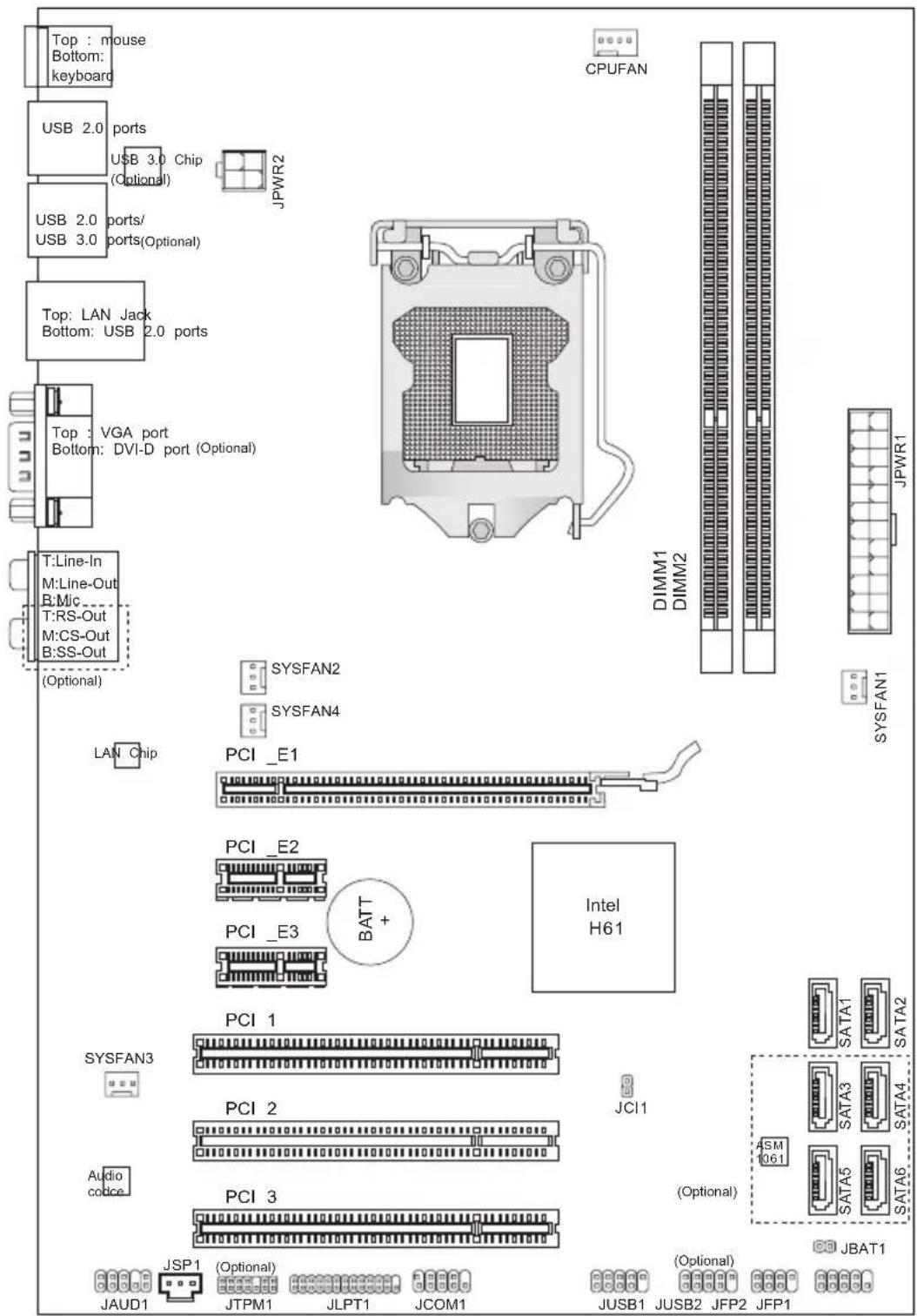
text_image
Top : mouse Bottom: keyboard USB 2.0 ports USB 3.0 Chip (Optional) USB 2.0 ports/ USB 3.0 ports(Optional) Top: LAN Jack Bottom: USB 2.0 ports Top : VGA port Bottom: DVI-D port (Optional) T:Line-In M:Line-Out B:Mic T:RS-Out M:CS-Out B:SS-Out (Optional) CPUFAN DIMM1 DIMM2 JPYWR1 JPYWR2 SYSFAN2 SYSFAN4 LAN Chip PCI _E1 PCI _E2 PCI _E3 BATT + Intel H61 SYSFAN1 JPYWR1 SYSFAN3 PCI 1 SYSFAN3 PCI 2 JCI1 Audio code PCI 3 JSP1 (Optional) JAUD1 JTPM1 JLPT1 JCOM1 JUSB1 JUSB2 JFP2 JFP1 (Optional) JBAT1 JDATA1 SATA2 SATA3 SATA4 ASM 1061 SATA5 SATA6PH61A-P35 (B3)/ PH61-P33 (B3)/ PH61-SP35 (B3) Series (MS-7732 v1.X) ATX Mainboard
Packing Contents
text_image
Mainboard
text_image
Driver / Utility DVD
text_image
User Guide Ba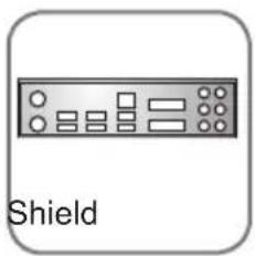
text_image
Shield
natural_image
SATA Cable cable with a black strap, shown in grayscale (no text or symbols on the cable itself)Optional Accessories

text_image
SATA Power Cable
natural_image
Abstract illustration of a globe with orbiting lines and digital elements, no text or symbols present.Chapter 2
Hardware Setup
This chapter provides you with the information about hardware setup procedures. While performing the installation, be careful in holding the components and following the installation procedures. For some components, if you install in the wrong orientation, the components will not work properly.
Use a grounded wrist strap before handling computer components. Static electricity may damage the components.
Quick Components Guide
text_image
SYSFAN2/4, p.2-14 JPWR2, p.2-10 CPU, p.2-4 CPUFAN1, p.2-14 DDR3, p.2-8 Back Panel, p.2-11 PCIE, p.2-20 JSP1, p.2-16 JTPM1, p.2-17 JCOM1, p.2-16 JLPT1, p.2-18 JUSB1~2, p.2-15 JCP1, p.2-19 JBAT1, p.2-19 SATA, p.2-13 JCP1, p.2-10 SYSFAN1, p.2-14 JCI1, p.2-18 JFP1/ JFP2, p.2-14Mounting Screw Holes
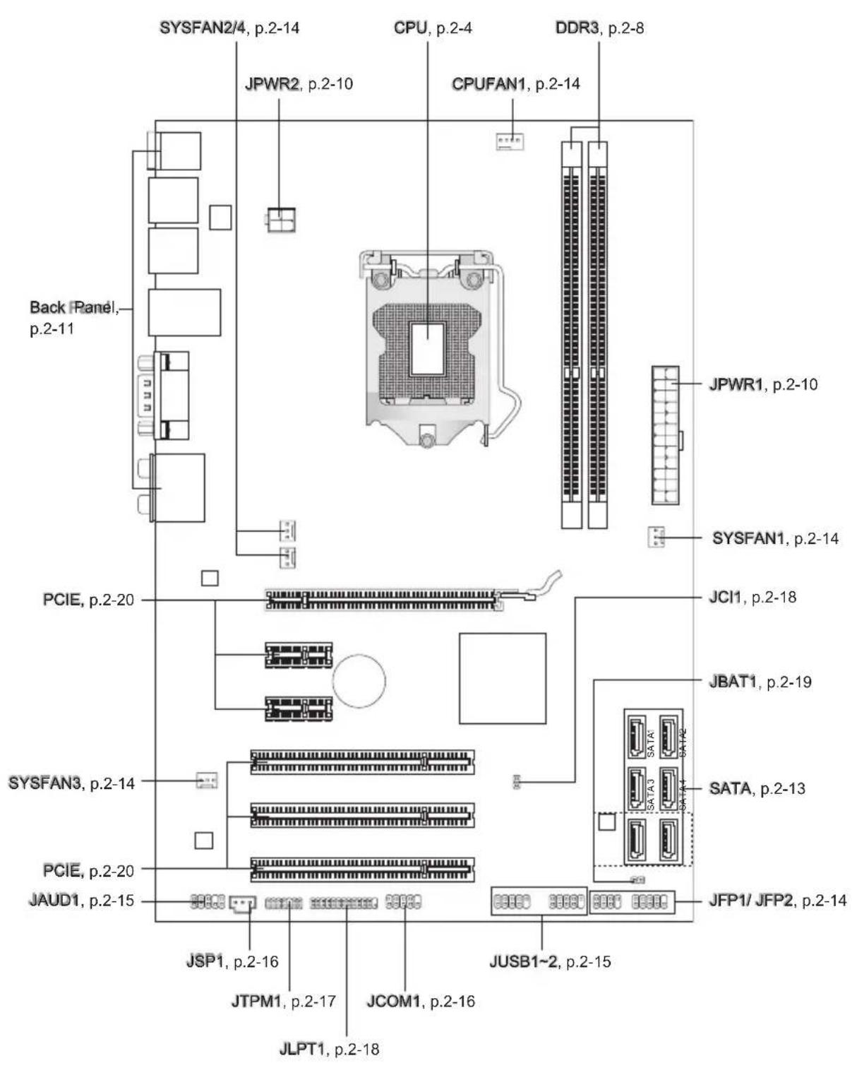
When you install the mainboard, you have to place the mainboard into the chassis in the correct direction. The locations of screws holes on the mainboard are shown as below.
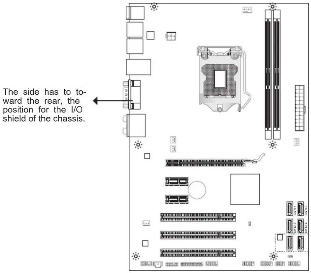
text_image
The side has to toward the rear, the position for the I/O shield of the chassis.
Refer above picture to install standoffs in the appropriate locations on chassis and then screw through the mainboard screw holes into the standoffs.
Important
- To prevent damage to the mainboard, any contact between the mainboard circuit and chassis or unnecessary standoffs mounted on the chassis is prohibited.
- Please make sure there are no metal components placed on the mainboard or within the chassis that may cause short circuit of the mainboard.
CPU (Central Processing Unit)
When you are installing the CPU, make sure to install the cooler to prevent overheating. If you do not have the CPU cooler, consult your dealer before turning on the computer.
For the latest information about CPU, please visit
http://www.msi.com/service/cpu-support
Important
Overheating
Overheating will seriously damage the CPU and system. Always make sure the cooling fan can work properly to protect the CPU from overheating. Make sure that you apply an even layer of thermal paste (or thermal tape) between the CPU and the heatsink to enhance heat dissipation.
Replacing the CPU
While replacing the CPU, always turn off the ATX power supply or unplug the power supply's power cord from the grounded outlet first to ensure the safety of CPU.
Overclocking
This mainboard is designed to support overclocking. However, please make sure your components are able to tolerate such abnormal setting, while doing overclocking. Any attempt to operate beyond product specifications is not recommended. We do not guarantee the damages or risks caused by inadequate operation or beyond product specifications.
Introduction to LGA 1155 CPU
The surface of LGA 1155 CPU. Remember to apply some thermal paste on it for better heat dispersion.
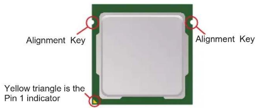
text_image
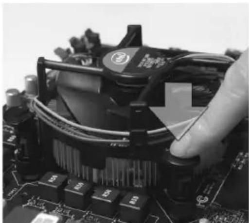
Alignment Key Alignment Key Yellow triangle is the Pin 1 indicatorCPU & Cooler Installation
When you are installing the CPU, make sure the CPU has a cooler attached on the top to prevent overheating. Meanwhile, do not forget to apply some thermal paste on CPU before installing the heat sink/cooler fan for better heat dispersion.
Follow the steps below to install the CPU & cooler correctly. Wrong installation will cause the damage of your CPU & mainboard.
-
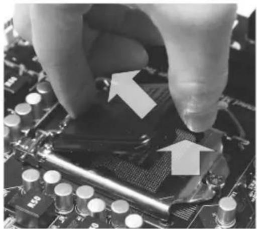
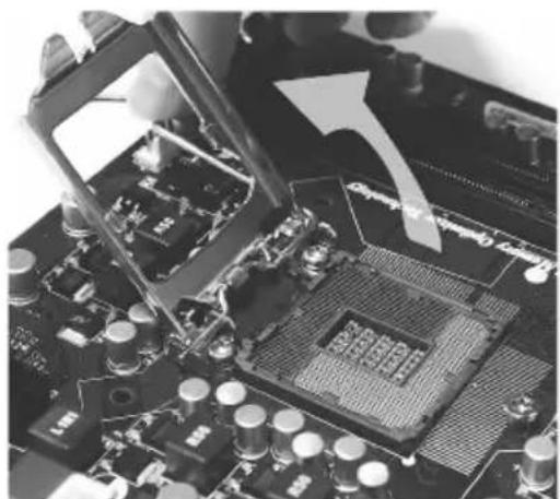
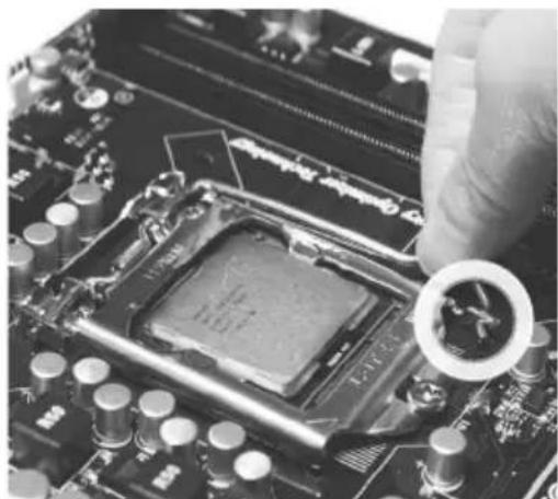
The CPU socket has a plastic cap on it to protect the contact from damage. Before you install CPU, always cover it to protect the socket pin. Remove the cap (as the arrow shows).
-
Open the load level.
natural_image
Close-up of a hand pressing down on a computer motherboard with CPU socket and cooling elements (no visible text or symbols)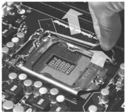
natural_image
Close-up of a computer motherboard with a hand inserting a component (no visible text or symbols)-
At least then for a right side of the following composition.
-
correct mating, put down the CPU in the socket housing frame. Be sure to grasp on the edge of the CPU base. Note that the alignment keys are matched.
natural_image
Close-up of a computer motherboard with visible CPU socket and circuit board (no text or symbols)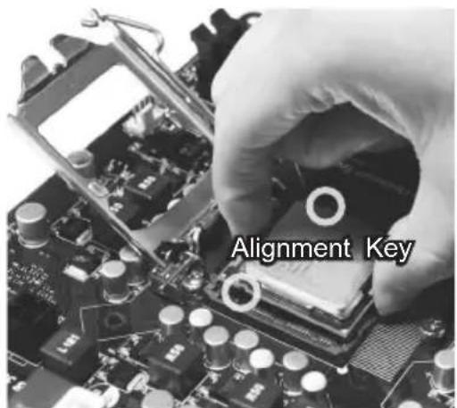
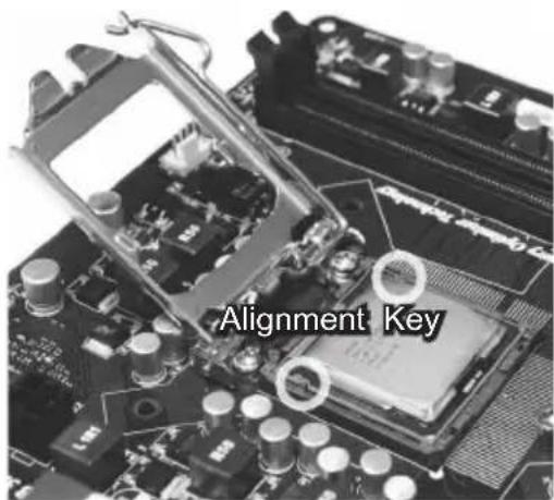
text_image
Alignment Key-
Envisagally this spacct of the vCRp is pressed well into the socket. If not, take out the CPU with pure vertical motion and reinstall.
-
down lightly onto the load plate.
text_image
Alignment Key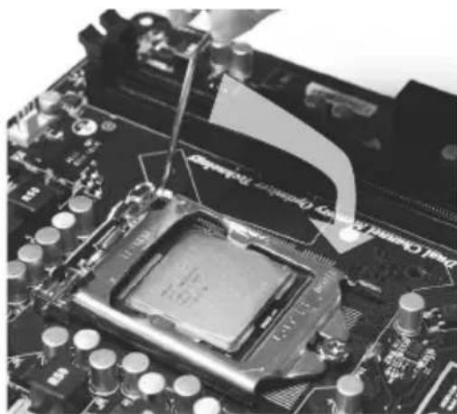
natural_image
Close-up of a computer motherboard with a CPU socket and a tool inserted, showing no visible text or symbols.-
Make user the above book show end under the retention tab.
-
proper position before you install the cooler.
natural_image
Close-up of a computer motherboard with a hand adjusting the chip (no visible text or symbols)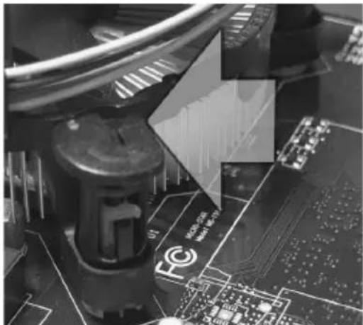
natural_image
Close-up of a robotic arm assembling a circuit board with visible traces and components (no readable text or symbols)Important
- Confirm if your CPU cooler is firmly installed before turning on your system.
-
Do not touch the CPU socket pins to avoid damaging.
-
Select the wood shook down again faster with the heatsink. Push down the cooler until its four clips get wedged into the holes of the mainboard.
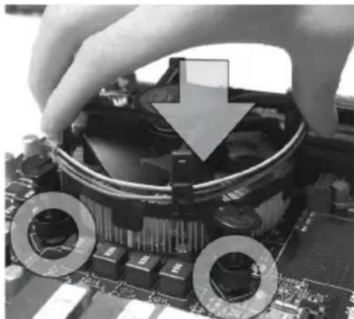
natural_image
Close-up of hands installing a CPU socket on a motherboard, with arrows indicating the cooling mechanism (no text or symbols visible)- Finally, vattable the QD and to cello into that the clip-ends are correctly inserted.
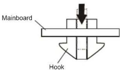
text_image
Mainboard Hook- the cooler.
natural_image
Close-up of a CPU socket with cooling fan and heatsink, hand adjusting the socket (no visible text or symbols)- the CPU fan connector on the main-board.
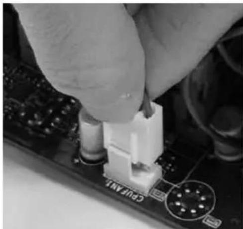
natural_image
Close-up of a hand inserting a small component into a computer motherboard (no visible text or symbols)Important
- Read the CPU status in BIOS.
- Whenever CPU is not installed, always protect your CPU socket pin with the plastic cap covered (shown in Figure 1) to avoid damaging.
- Mainboard photos shown in this section are for demonstration of the CPU/ cooler installation only. The appearance of your mainboard may vary depending on the model you purchase.
- Please refer to the documentation in the CPU fan package for more details about the CPU fan installation.
Memory
These DIMM slots are used for installing memory modules. For more information on compatible components, please visit http://www.msi.com/service/test-report
DDR3
240-pin, 1.5V
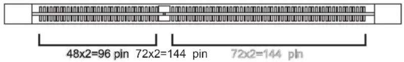
text_image
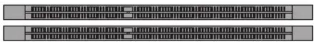
48x2=96 pin 72x2=144 pin 72x2=144 pinDual-Channel mode Population Rule
In Dual-Channel mode, the memory modules can transmit and receive data with two data bus lines simultaneously. Enabling Dual-Channel mode can enhance the system performance. The following illustrations explain the population rules for Dual-Channel mode.
DIMM1
DIMM2
natural_image
Two identical rectangular panels with horizontal lines and grid patterns, no text or symbols visible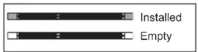
text_image
Installed EmptyImportant
- DDR3 memory modules are not interchangeable with DDR2, and the DDR3 standard is not backwards compatible. You should always install DDR3 memory modules in the DDR3 DIMM slots.
- In Dual-Channel mode, make sure that you install memory modules of the same type and density in different channel DIMM slots.
- Due to the chipset resource deployment, the system density will only be detected up to 15+GB (not full 16GB) when each DIMM is installed with a 8GB memory module.
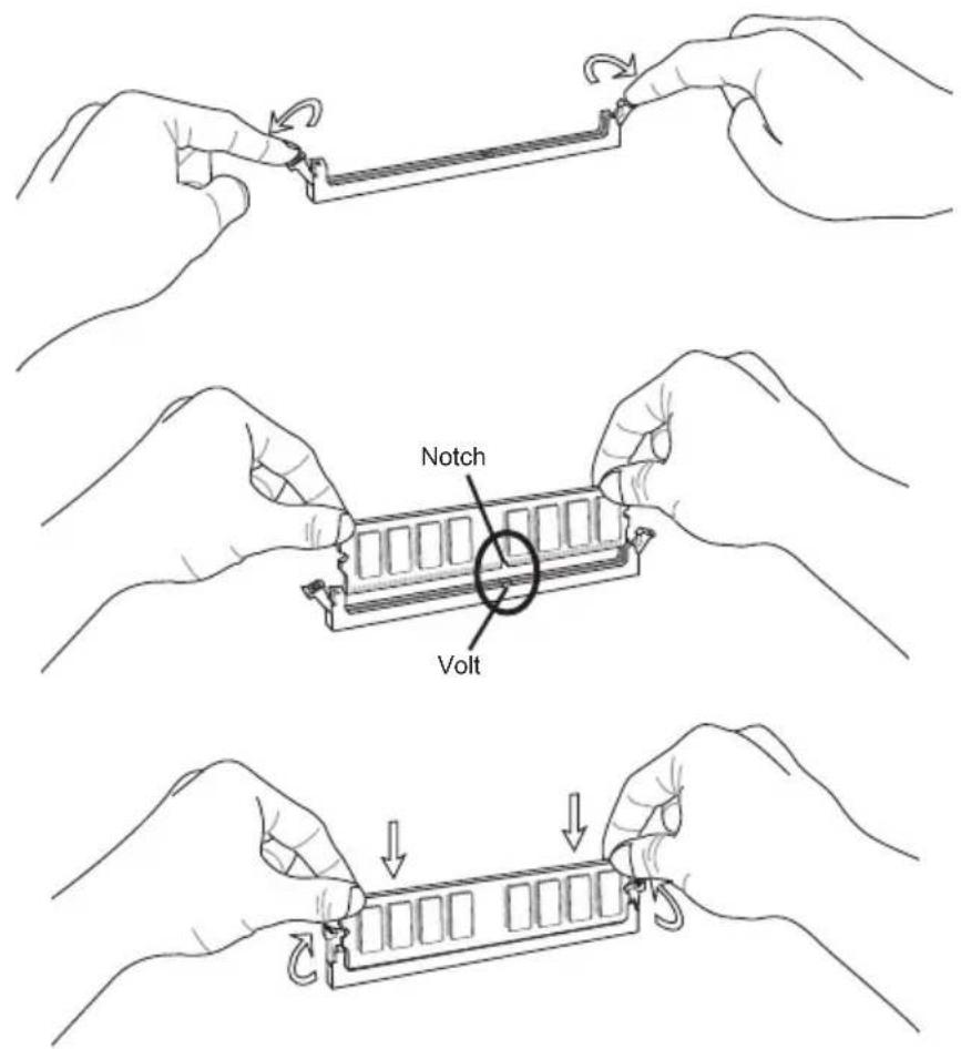
Installing Memory Modules
- The memory module has only one notch on the center and will only fit in the right orientation.
- Insert the memory module vertically into the DIMM slot. Then push it in until the golden finger on the memory module is deeply inserted in the DIMM slot. The plastic clip at each side of the DIMM slot will automatically close when the memory module is properly seated.
- Manually check if the memory module has been locked in place by the DIMM slot clips at the sides.
text_image
Notch VoltImportant
You can barely see the golden finger if the memory module is properly inserted in the DIMM slot.
Power Supply
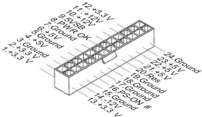
ATX 24-pin Power Connector: JPWR1
This connector allows you to connect an ATX 24-pin power supply. To connect the ATX 24-pin power supply, make sure the plug of the power supply is inserted in the proper orientation and the pins are aligned. Then push down the power supply firmly into the connector.
You may use the 20-pin ATX power supply as you like. If you'd like to use the 20-pin ATX power supply, please plug your power supply along with pin 1 & pin 13.
text_image
12+3.3V 11+12V 9.5VSB 7.Ground 6+5V 5.Ground 4+5V 3.Ground 2+3.3V 1+3.3V 24.Ground 23+5V 22+5V 20.Res 19.Ground 18.Ground 17.Ground 16.PS-ON # 15.Ground 14-12V 13+3.3VATX 4-pin Power Connector: JPWR2
This connector is used to provide the power output to the CPU.

text_image
1. Ground 2. Ground 3. +12V 4. +12VImportant
Make sure that all the connectors are connected to proper ATX power supplies to ensure stable operation of the mainboard.
Back Panel
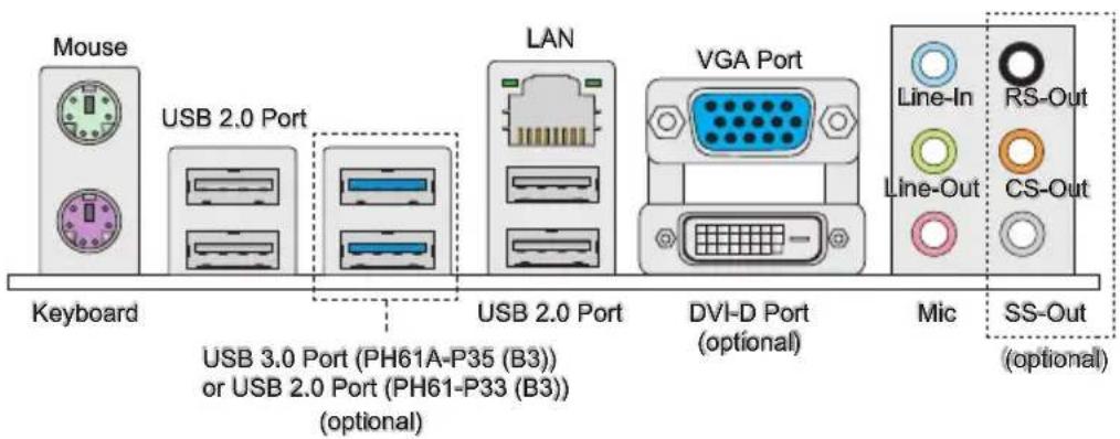
text_image
Mouse USB 2.0 Port Keyboard USB 3.0 Port (PH61A-P35 (B3)) or USB 2.0 Port (PH61-P33 (B3)) (optional) LAN VGA Port DVI-D Port (optional) Mic RS-Out Line-In Line-Out CS-Out (SS-Out (optional)▶ Mouse/Keyboard
The standard PS/2 ^® mouse/keyboard DIN connector is for a PS/2 ^® mouse/keyboard.
▶ USB 2.0 Port
The USB 2.0 port is for attaching USB devices such as keyboard, mouse, or other USB-compatible devices.
▶ USB 3.0 Port (optional)
USB 3.0 port is backward-compatible with USB 2.0 devices. Supports data transfer rate up to 5 Gbit/s (SuperSpeed).
Important
If you want to use a USB 3.0 device, you must use the USB 3.0 cable to connect to the USB 3.0 port.
▶ VGA Port
The DB15-pin female connector is provided for monitor.
▶ DVI-D Port (optional)
The DVI-D (Digital Visual Interface - Digital) connector allows you to connect a LCD monitor. It provides a high-speed digital interconnection between the computer and its display device. To connect an LCD monitor, simply plug your monitor cable into the DVI-D connector, and make sure that the other end of the cable is properly connected to your monitor (refer to your monitor manual for more information.)
Important
The VGA and DVI-D display interfaces on the mainboard are designed to serve as IGP (Integrated Graphics Processor) used. If you installed a processor without integrated graphics chip, these display ports will have no effect.
▶ LAN
The standard RJ-45 LAN jack is for connection to the Local Area Network (LAN). You can connect a network cable to it.
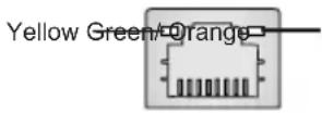
| LED Color LED State Condition | |||
| Left Yellow Off LAN link is not established. | |||
| On(Steady state) LAN link is established. | |||
| On(brighter & pulsing) The computer is communicating with another computer on the LAN. | |||
| Right | Green Off 10 Mbit/sec data rate is selected. | ||
| Orange On 1000 Mbit/sec data rate is selected. | |||
▶ Audio Ports
These audio connectors are used for audio devices. It is easy to differentiate between audio effects according to the color of audio jacks.
■ Line-In: Blue - Line In, is used for external CD player, tape-player or other audio devices.
■ Line-Out: Green - Line Out, is a connector for speakers or headphones.
■ Mic: Pink - Mic, is a connector for microphones.
■ RS-Out (optional): Black - Rear-Surround Out in 4/5.1/7.1 channel mode.
■ CS-Out (optional): Orange - Center/ Subwoofer Out in 5.1/ 7.1 channel mode.
■ SS-Out (optional): Gray - Side-Surround Out 7.1 channel mode.
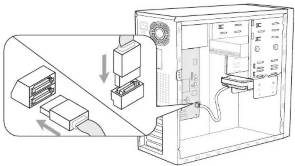
Connectors
Serial ATA Connector: SATA1\~6 (SATA3\~6 are optional)
This connector is a high-speed Serial ATA interface port. Each connector can connect to one Serial ATA device.
text_image
Diagram showing computer setup with labeled components and directional arrows indicating connection or movement* The MB layout in this figure is for reference only.
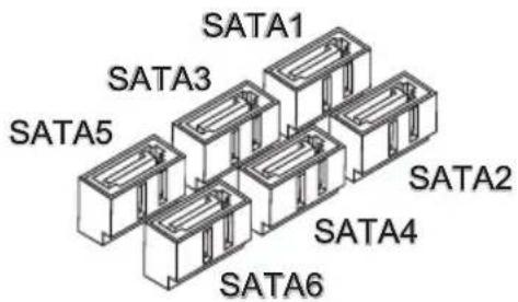
text_image
SATA1 SATA3 SATA5 SATA2 SATA4 SATA6SATA1\~4 (3Gb/s, by H61)
SATA5\~6 (6Gb/s, by ASM1061)
Important
Please do not fold the Serial ATA cable into a 90-degree angle. Otherwise, data loss may occur during transmission.
Fan Power Connectors: CPUFAN,SYSFAN1\~4
The fan power connectors support system cooling fan with +12V. When connecting the wire to the connectors, always note that the red wire is the positive and should be connected to the +12V; the black wire is Ground and should be connected to GND. If the mainboard has a System Hardware Monitor chipset on-board, you must use a specially designed fan with speed sensor to take advantage of the CPU fan control.
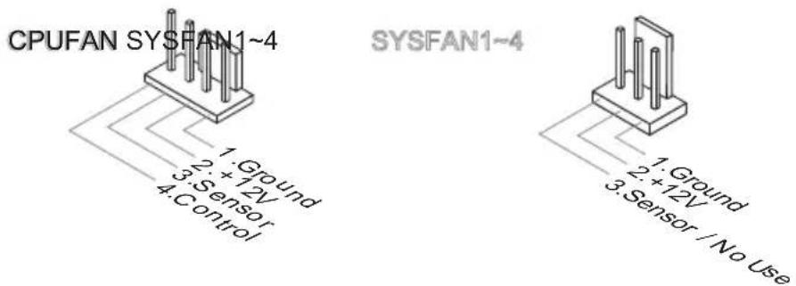
text_image
CPUFAN SYSFAN1~4 1. Ground 2. +12V 3. Sensor 4. Control SYSFAN1~4 1. Ground 2. +12V 3. Sensor / No UseImportant
- Please refer to the recommended CPU fans at processor's official website or consult the vendors for proper CPU cooling fan.
- CPUFAN support Smart fan control. You can install Control Center utility that will automatically control the CPUFAN speeds according to the actual CPUFAN temperatures.
- Fan cooler set with 3 or 4 pins power connector are both available for CPUFAN.
Front Panel Connectors: JFP1, JFP2
These connectors are for electrical connection to the front panel switches and LEDs. The JFP1 is compliant with Intel® Front Panel I/O Connectivity Design Guide.
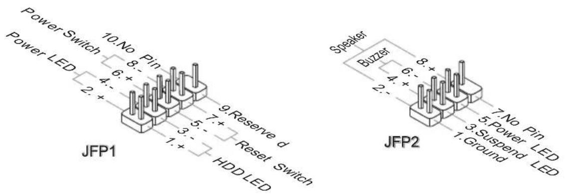
text_image
Power Switch 10. No Pin 6. + Power LED 2. + JFP1 9. Reserve d 5. - Reset Switch 3. - HDD LED Speaker Buzzer 8. + 7. No Pin 6. - 5. Power LED 4. + JFP2 3. Suspend LED 1. Ground 2.Front USB Connector: JUSB1\~2 (JUSB2 is optional)
This connector, compliant with Intel ^ I/O Connectivity Design Guide, is ideal for connecting high-speed USB interface peripherals such as USB HDD, digital cameras, MP3 players, printers, modems and the like.
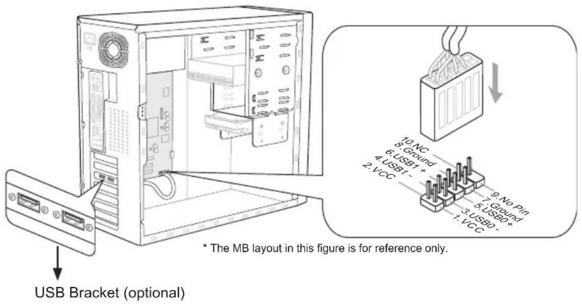
text_image
USB Bracket (optional) * The MB layout in this figure is for reference only.Important
Note that the pins of VCC and GND must be connected correctly to avoid possible damage.
Front Panel Audio Connector: JAUD1
This connector allows you to connect the front panel audio and is compliant with Intel® Front Panel I/O Connectivity Design Guide.
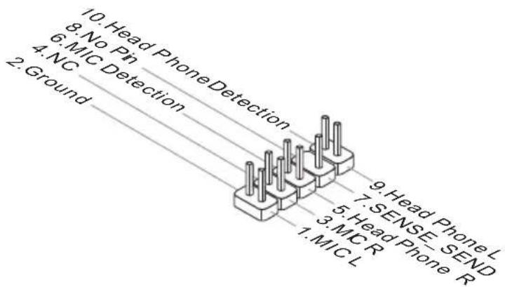
flowchart
graph TD
    A["1. MIC L"] --> B["2. Ground"]
    C["3. MIC R"] --> D["4. NC"]
    E["5. SENSE_SEND"] --> F["6. MIC Detection"]
    G["7. Head Phone L"] --> H["8. No Pin"]
    I["9. Head Phone Detection"] --> J["10. Head Phone Detection"]
S/PDIF-Out Connector: JSP1
This connector is used to connect S/PDIF (Sony & Philips Digital Interconnect Format) interface for digital audio transmission.
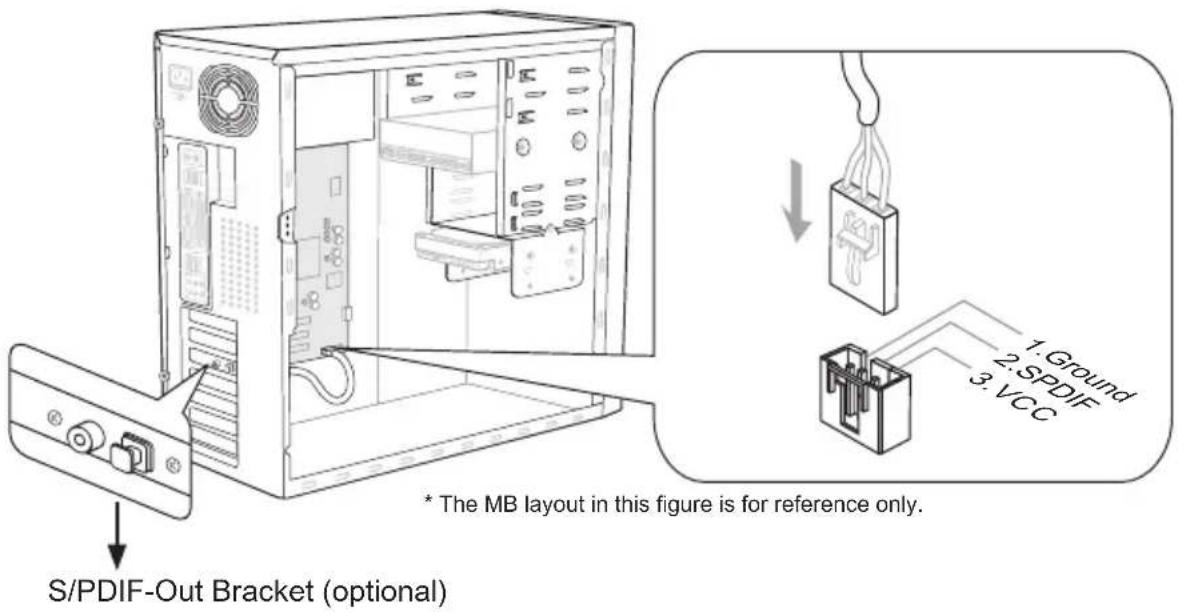
text_image
S/PDIF-Out Bracket (optional) * The MB layout in this figure is for reference only. 1: Ground 2: SPDIF 3: VCCSerial Port Connector: JCOM1
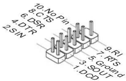
This connector is a 16550A high speed communication port that sends/receives 16 bytes FIFOs. You can attach a serial device.
text_image
10.No Pin 8.CTS 6.DSR 4.DTR 2.SIN 9.RI 7.RTS 5.Ground 3.SOUT 1.DCDTPM Module connector: JTPM1 (optional)
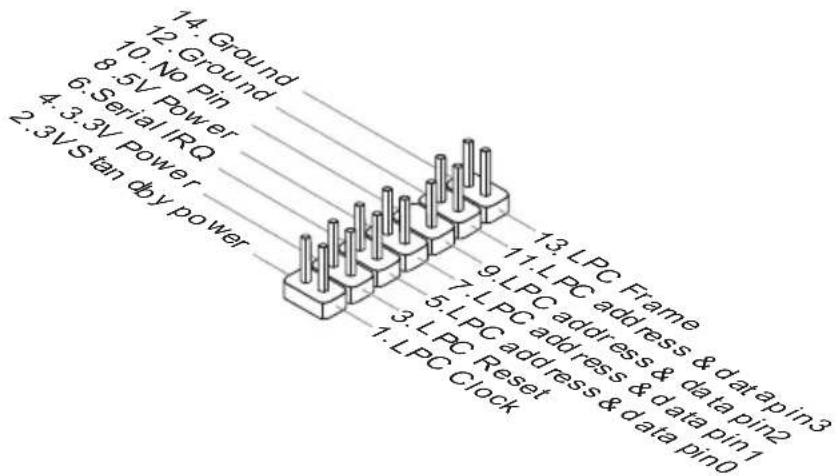
This connector connects to a TPM (Trusted Platform Module) module (optional). Please refer to the TPM security platform manual for more details and usages.
text_image
14. Ground 12. Ground 10. No Pin 8.5V Power 6. Serial IRQ 4.3.3V Power 2.3VS tan db y power 13. LPC Frame 11. LPC address & data pin2 9. LPC address & data pin1 7. LPC address & data pin0 5. LPC address & data pin1 3. LPC Reset 1. LPC Clock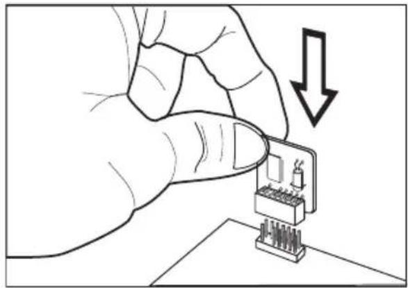
natural_image
Illustration of a hand inserting a component into a microchip with a downward arrow indicating compression (no text or symbols)Parallel Port Connector: JLPT1
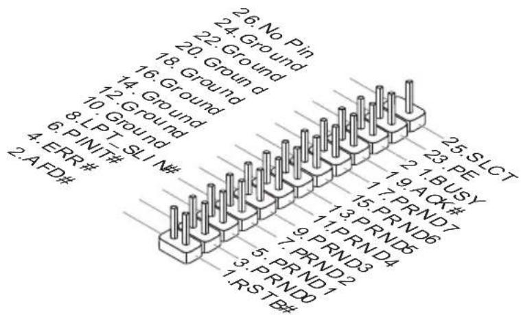
This connector is used to connect an optional parallel port bracket. The parallel port is a standard printer port that supports Enhanced Parallel Port (EPP) and Extended Capabilities Parallel Port (ECP) mode.
text_image
26. No Pin 24. Ground 22. Ground 18. Ground 16. Ground 14. Ground 10. Ground 8. LPT SLI N# 4. ERR# 2. AFD# 25. SLCT 23. PE 1. BUSY 1.9 ACK# 15. PRND7 13. PRND6 11. PRND5 9. PRND3 7. PRND2 5. PRND1 3. PRND0 1. RSTB#Chassis Intrusion Connector: JCI1
This connector connects to the chassis intrusion switch cable. If the chassis is opened, the chassis intrusion mechanism will be activated. The system will record this status and show a warning message on the screen. To clear the warning, you must enter the BIOS utility and clear the record.
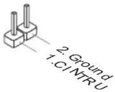
text_image
2. Ground 1: C1 NTR UJumper
Clear CMOS Jumper: JBAT1
There is a CMOS RAM on board with an external battery power supply to preserve the system configuration data. With the CMOS RAM, the system can automatically boot OS every time it is turned on. If you want to clear the system configuration, please temporarily short these two pins to clear data by using a metal object.


Keep Data Clear Data
(Use a metal object to temporarily short these two pins.)
Important
You can clear CMOS by touching two pins once with a metal object while the system is off. Avoid clearing the CMOS while the system is on; it will damage the mainboard.
Slots
PCIE (Peripheral Component Interconnect Express) Slot
The PCIE slot supports the PCIE interface expansion card.
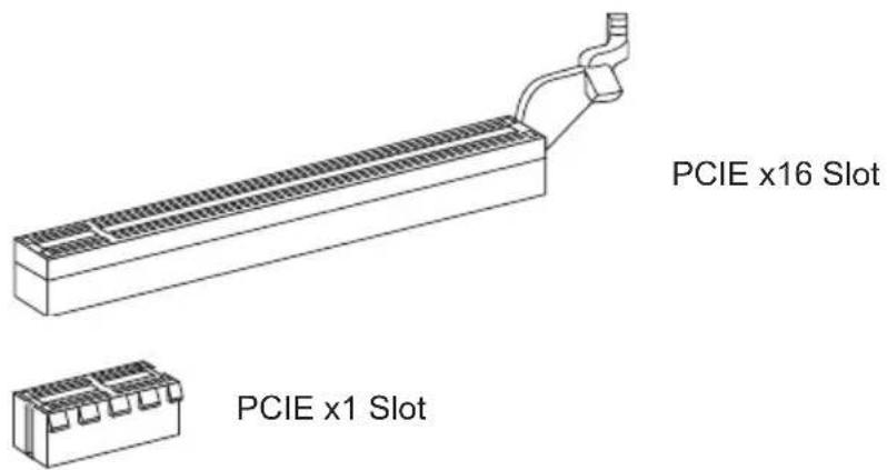
text_image
PCIE x16 Slot PCIE x1 SlotPCI (Peripheral Component Interconnect) Slot
The PCI slot supports LAN card, SCSI card, USB card, and other add-on cards that comply with PCI specifications.
text_image
32-bit PCI SlotImportant
When adding or removing expansion cards, make sure that you unplug the power supply first. Read the documentation for the expansion card to configure any necessary hardware or software settings, such as jumpers, switches or BIOS configuration.
PCI Interrupt Request Routing
IRQ, or interrupt request line, are hardware lines over which devices can send interrupt signals to the microprocessor. The PCI IRQ pins are typically connected to the PCI bus pins as follows:
| Order1 Order2 Order3 Order4 | |
| PCI Slot 1 INT A# INT B# INT C# INT D# | |
| PCI Slot 2 INT B# INT C# INT D# INT A# | |
| PCI Slot 3 INT C# INT D# INT A# INT B# | |

natural_image
Abstract illustration of a globe with orbital lines and abstract light effects (no text or symbols)Chapter 3
BIOS Setup
This chapter provides information on the BIOS Setup program and allows you to configure the system for optimum use.
You may need to run the Setup program when:
■ An error message appears on the screen during the system booting up, and requests you to run SETUP.
■ You want to change the default settings for customized features.
Entering Setup
Power on the computer and the system will start POST (Power On Self Test) process. When the message below appears on the screen, press key to enter Setup.
Press DEL to enter Setup Menu, F11 to enter Boot Menu
If the message disappears before you respond and you still wish to enter Setup, restart the system by turning it OFF and On or pressing the RESET button. You may also re-start the system by simultaneously pressing
Important
- The items under each BIOS category described in this chapter are under continuous update for better system performance. Therefore, the description may be slightly different from the latest BIOS and should be held for reference only.
- Upon boot-up, the 1st line appearing after the memory count is the BIOS version. It is usually in the format:
E7732IMS.xxx 022811 where:
1st digit refers to BIOS type as E = EFI
2nd - 5th digit refers to the model number.
6th digit refers to the chipset as I = Intel, N = nVidia, A = AMD and V = VIA.
7th - 8th digit refers to the customer as MS = all standard customers.
xxx refers to the BIOS version.
022811 refers to the date this BIOS was released.
Control Keys
| <↑><↓> Select Item | |
| <←><→> Select Screen | |
| Select | |
| Jumps to the Exit menu or returns to the main menu from a submenu | |
| <+><-> Change Option | |
| General Help | |
| Load Optimized Defaults | |
| Save all the CMOS changes and exit | |
Getting Help
After entering the Setup menu, the first menu you will see is the Main Menu.
Main Menu
The main menu lists the setup functions you can make changes to. You can use the arrow keys (↑↓) to select the item. The on-line description of the highlighted setup function is displayed at the bottom of the screen.
Sub-Menu
If you find a right pointer symbol (as shown in the right view) appears to the left of certain fields that means a sub-menu can be launched from this field. A sub-menu contains additional options for a field parameter. You can use arrow keys (↑↓) to highlight the field and press
General Help
The BIOS setup program provides a General Help screen. You can call up this screen from any menu by simply pressing
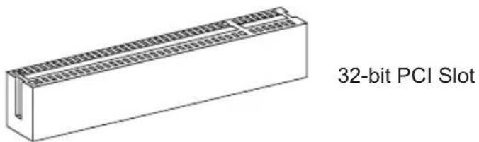
The Menu Bar
text_image
Aptio Setup Utility - Copyright (C) 2011 American Megatrends, Inc. Main Menu Advanced Overclocking M-Flash Security Boot Save & Exit System Date [Tue 02/22/2011] System Time [00:07:39] SATA Port1 Not Present SATA Port2 Not Present SATA Port3 Not Present SATA Port4 ST3320618AS (320.0GB) System Information Intel(R) Core(TM) i7-2600K CPU @ 3.40GHz CPUID/MicroCode 20686/2B BIOS Version E7732IMS V1.084 Build Date 02/22/2011 Physical Memory 2048 MB Cache Size 1024 KB L3 Cache Size 8192 KB Set the Date. Use Tab to switch between Data elements. ++: Select Screen T↓: Select Item Enter: Select +/-: Change Opt. F1: General Help F6: Optimized Defaults ESC: Exit F10: Save & Reset Version 2.10.1208. Copyright (C) 2011 American Megatrends, Inc.▶ Main Menu
Use this menu for basic system configurations, such as time, date etc.
▶ Advanced
Use this menu to setup the items of the BIOS special enhanced features, integrated peripherals, power management and PC health status.
▶ Overclocking
Use this menu to specify your settings for frequency/voltage control and overclocking.
▶ M-Flash
Use this menu to read/ flash the BIOS from storage drive (FAT/ FAT32 format only).
▶ Security
Use this menu to set supervisor and user passwords.
▶ Boot
Use this menu to specify the priority of boot devices.
▶ Save & Exit
This menu allows you to load the BIOS default values or factory default settings into the BIOS and exit the BIOS setup utility with or without changes.
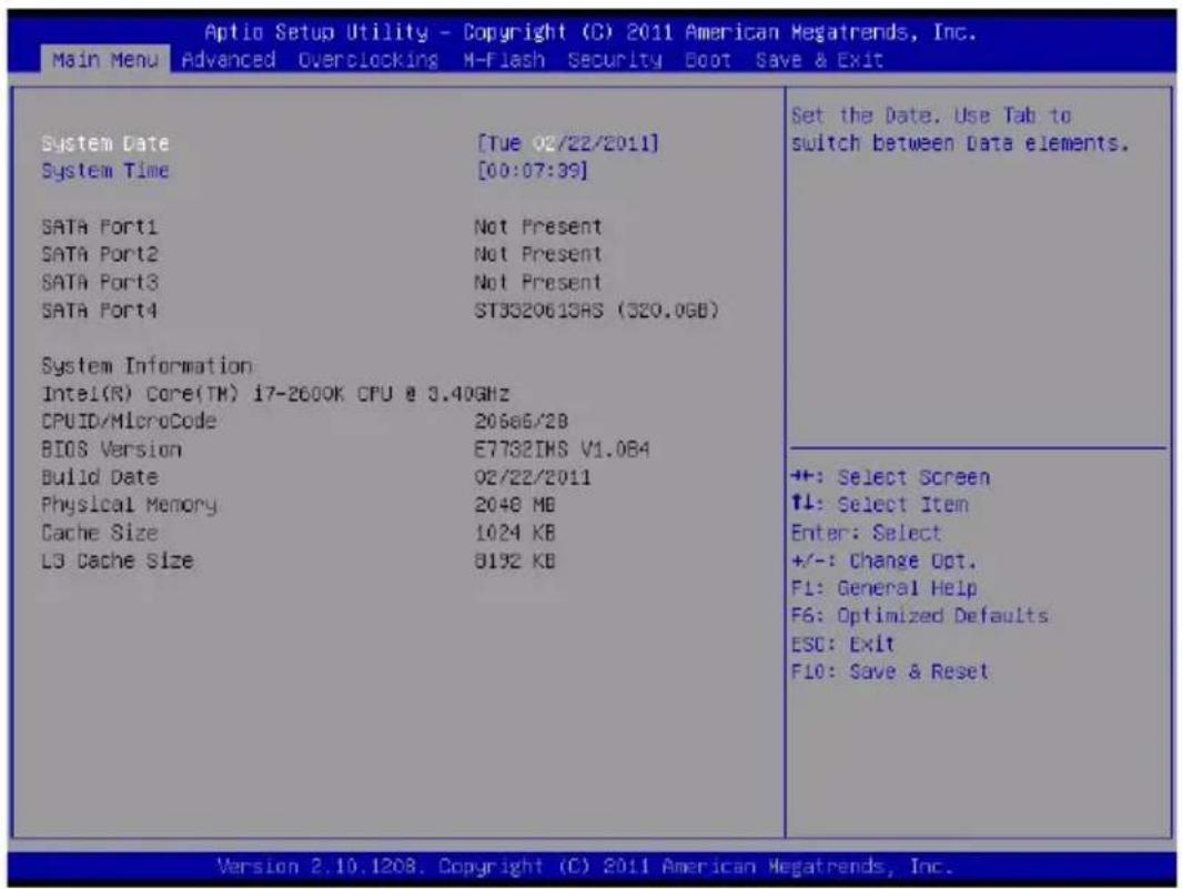
Main Menu

text_image
Aptio Setup Utility - Copyright (C) 2011 American Megatrends, Inc. Main Menu Advanced Overclocking M-Flash Security Boot Save & Exit System Date [Tue 02/22/2011] System Time [00:07:39] SATA Port1 Not Present SATA Port2 Not Present SATA Port3 Not Present SATA Port4 ST3320618AS (320.0GB) System Information Intel(R) Core(TM) i7-2600K CPU @ 3.40GHz CPUID/MicroCode 20686/2B BIOS Version E7732IMS V1.084 Build Date 02/22/2011 Physical Memory 2048 MB Cache Size 1024 KB L3 Cache Size 8192 KB Set the Date. Use Tab to switch between Data elements. ++: Select Screen T↓: Select Item Enter: Select +/-: Change Opt. F1: General Help F6: Optimized Defaults ESC: Exit F10: Save & Reset Version 2.10.1208. Copyright (C) 2011 American Megatrends, Inc.▶ System Date
This allows you to set the system to the date that you want (usually the current date). The format is
[day] Day of the week, from Sun to Sat, determined by BIOS. Read-only.
[month] The month from Jan. through Dec.
[date] The date from 1 to 31 can be keyed by numeric function keys.
[year] The year can be adjusted by users.
▶ System Time
This allows you to set the system time that you want (usually the current time). The time format is
▶ SATA Port1\~6
Press
Important
SATA Port1\~6 are appearing when you connect the HD devices to the SATA connectors on the mainboard.
▶ System Information
This area shows the CPU information, BIOS version and memory status of your system (read only).
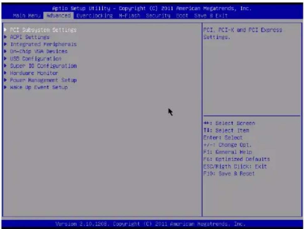
Advanced
text_image
Aptio Setup Utility - Copyright (C) 2011 American Megatrends, Inc. Main Menu Advanced Overclocking M-Flash Security Boot Save & Exit PCI Subsystem Settings ACPI Settings Integrated Peripherals On-Chip VGA Devices USB Configuration Super IO Configuration Hardware Monitor Power Management Setup Make Up Event Setup PCI, PCI-K and PCI Express Settings. ++: Select Screen T4: Select Item Enter: Select +/-: Change Opt. F1: General Help F6: Optimized Defaults ESC/Righth Click: Exit F10: Save & Reset Version 2.10.1209, Copyright (C) 2011 American Megatrends, Inc.▶ PCI Subsystem Settings
Press

text_image
Optio Setup Utility - Copyright (C) 2011 American Megatrends, Inc. Advanced PCI Latency Timer [32 PCI Bus Clocks] Value to be programmed into PCI Latency Timer Register.▶ PCI Latency Timer
This item controls how long each PCI device can hold the bus before another takes over. When set to higher values, every PCI device can conduct transactions for a longer time and thus improve the effective PCI bandwidth. For better PCI performance, you should set the item to higher values.
▶ ACPI Settings
Press

text_image
Aptio Setup Utility - Copyright (C) 2011 American Megatrends, Inc. Advanced ACPI Standby State [S3] Power LED [Blinking] Select the highest ACPI sleep state the system will enter▶ACPI Standby State
This item specifies the power saving modes for ACPI function.
▶ Power LED
This item configures how the system uses power LED on the case to indicate the sleep/suspend state.
▶ Integrated Peripherals
Press
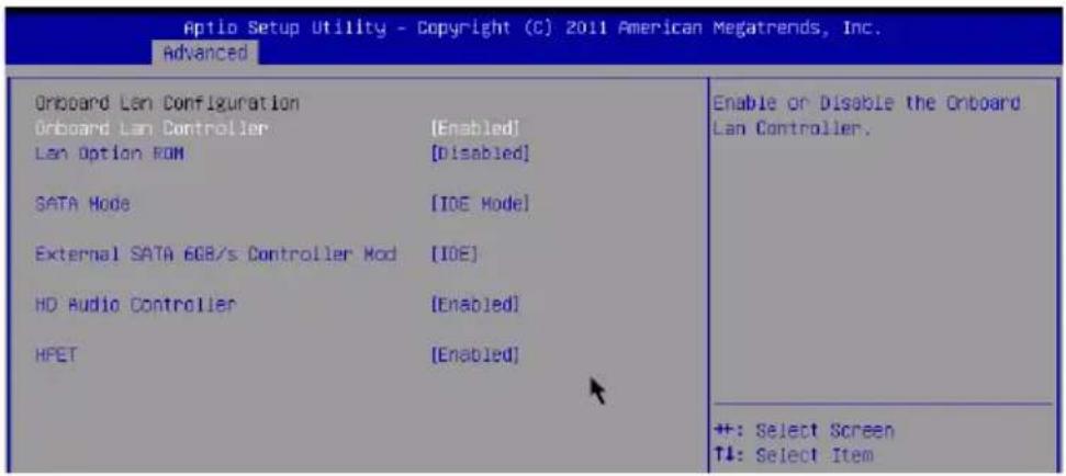
text_image
Aptio Setup Utility - Copyright (C) 2011 American Megatrends, Inc. Advanced Oriboard Lan Configuration Orboard Lan Controller [Enabled] Lan Option ROM [Disabled] SATA Mode [IOE Model] External SATA 6GB/s Controller Mod [IOE] HD Audio Controller [Enabled] HPET [Enabled] Enable or Disable the Onboard Lan Controller. ++: Select Screen ↑↓: Select Item▶ Onboard Lan Controller
This item allows you to enable/ disable the onboard LAN controller.
▶ LAN Option ROM
This item is used to decide whether to invoke the Boot ROM of the onboard LAN.
▶SATA Mode
This item is used to specify the mode for SATA port.
▶ External SATA 6GB/s Controller Mode
This item is used to specify the mode for SATA 6Gb/s port.
▶HD Audio Controller
This item allows you to enable/ disable the HD audio controller.
HPET
The HPET (High Precision Event Timers) is a component that is part of the chipset. You can to enable it, and will provide you with the means to get to it via the various ACPI methods.
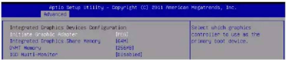
▶ On-Chip VGA Devices
Press
text_image
Aptio Setup Utility - Copyright (C) 2011 American Megatrends, Inc. Advanced Integrated Graphics Devices Configuration Initiate Graphic Adapter [PEG] Integrated Graphics Share Memory [64M] OVT Memory [256MB] IGD Multi-Monitor [Disabled] Select which graphics controller to use as the primary boot device.- Initiate Graphic Adapter
This setting specifies which graphic card is the initial graphics adapter.
▶ Integrated Graphics Share Memory
The system shares memory to the onboard graphic. This setting controls the exact memory size shared to the onboard graphic.
▶DVMT Memory
Specify the size of DVMT memory to allocate for video memory.
▶IGD Multi-Monitor
When "Enabled", the integrated graphics and extra graphics card can be configured as multi-monitor mode.
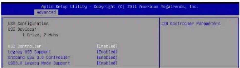
▶ USB Configuration
Press
text_image
Aptio Setup Utility - Copyright (C) 2011 American Megatrends, Inc. Advanced USB Configuration USB Devices: 1 Drive, 2 Hubs USB Controller [Enabled] Legacy USB Support [Enabled] Oriboard USB 3.0 Controller [Enabled] USB3.0 Legacy Mode Support [Enabled] USB Controller Parameters▶USB Devices:
This item shows the type of installed USB device.
▶USB Controller
This item allows you to enable/ disable the onchip USB controller.
▶ Legacy USB Support
Select [Enabled] if you need to use a USB2.0-interfaced device in the operating system.
▶ Onboard USB 3.0 Controller
This item allows you to enable/ disable the onboard USB 3.0 controller.
▶USB3.0 Legacy mode Support
Select [Enabled] if you need to use a USB3.0-interfaced device in the operating system.
▶ Super IO Configuration
Press
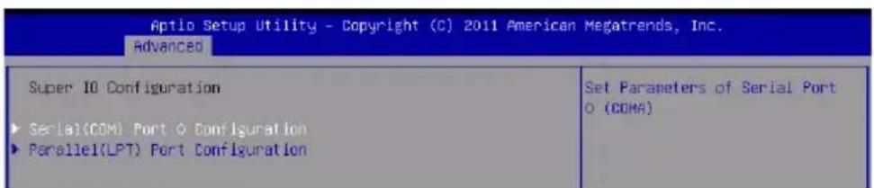
text_image
Aptio Setup Utility - Copyright (C) 2011 American Megatrends, Inc. Advanced Super IO Configuration ► Serial(COM) Port O Configuration ► Parallel(LPT) Port Configuration Set Parameters of Serial Port O (COMA)▶ Serial (COM) Port 0 Configuration
Press
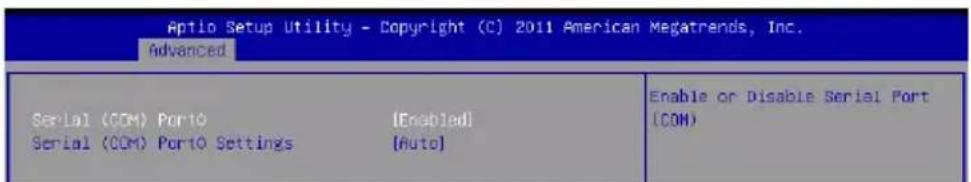
text_image
Aptio Setup Utility - Copyright (C) 2011 American Megatrends, Inc. Advanced Serial (COM) Port0 [Enabled] Serial (COM) Port0 Settings [Auto] Enable or Disable Serial Port (CON)▶ Serial (COM) Port0
This item allows you to enable/ disable the serial port.
▶ Serial (COM) Port0 Settings
Select an address and corresponding interrupt for the serial port.
▶Parallel (LPT) Port Configuration
Press
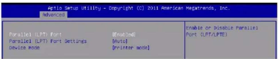
text_image
Aptio Setup Utility - Copyright (C) 2011 American Megatrends, Inc. Advanced Parallel (LPT) Port [Enabled] Parallel (LPT) Port Settings [Auto] Device Mode [Printer mode] Enable or Disable Parallel Port (LPT/LPTE)▶ Parallel (LPT) Port
This item allows you to enable/ disable the parallel port.
▶ Parallel (LPT) Port Settings
Select an address and corresponding interrupt for the serial port.
▶ Device Mode
Select a device mode for parallel port.
▶ Hardware Monitor
Press
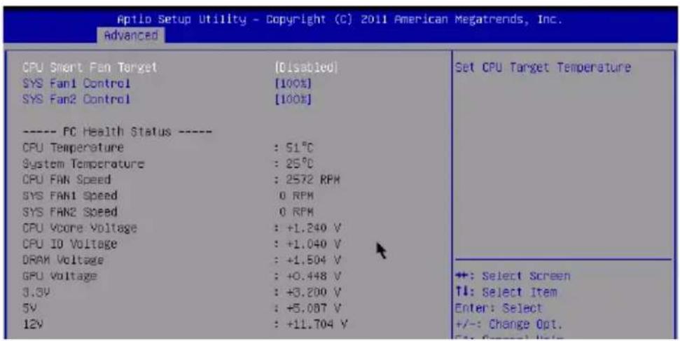
text_image
Aptio Setup Utility - Copyright (C) 2011 American Megatrends, Inc. Advanced CPU Short Fan Target [Disabled] SYS Fan1 Control [100%] SYS Fan2 Control [100%] ---- PC Health Status ---- CPU Temperature : 51°C System Temperature : 25°C CPU FAN Speed : 2572 RPM SYS FAN1 Speed 0 RPM SYS FAN2 Speed 0 RPM CPU VScore Voltage : +1.240 V CPU ID Voltage : +1.040 V DRAM Voltage : +1.504 V GPU Voltage : +0.448 V 3.3V : +3.200 V 5V : +5.087 V 12V : +11.704 V Set CPU Target Temperature ++: Select Screen TI: Select Item Enter: Select +/-: Change Opt. S: Forward Input▶CPU Smart Fan Target
The Smart Fan function controls the CPU fan speed automatically depending on the current temperature to keep it with in a specific range. You can enable a fan target value here. If the current CPU fan temperature reaches to the target value, the smart fan function will be activated.
▶SYS Fan 1 Control/ SYS Fan2 Control
These items allow users to select how percentage of speed for the SYSFAN1/ SYSFAN2.
▶CPU/ System Temperature, CPU FAN/ SYS FAN 1/2 Speed, CPU Vcore Voltage, CPU IO Voltage, DRAM Voltage, GPU Voltage, 3.3V, 5V, 12V
These items show the current status of all of the monitored hardware devices/components such as CPU voltage, temperatures and all fans' speeds.
▶ Power Management Setup
Press
text_image
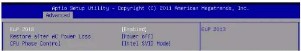
Aptio Setup Utility - Copyright (C) 2011 American Megatrends, Inc. Advanced EUP 2018 [Enabled] Eup 2013 Restore after AC Power Loss [Power off] CPU Phase Control [Intel SVIO Mode]▶EuP 2013
This item is designed for energy using products lot 6 2013 (EuP) aka energy related products (ErP); to reduce power consumption during system off or standby mode. Note: Enabling EuP 2013 will disable support for RTC Wake Up Event.
▶Restore after AC Power Loss
This item specifies whether your system will reboot after a power failure or interrupt occurs. Settings are:
[Power Off] Always leaves the computer in the power off state.
[Power On] Always leaves the computer in the power on state.
[Last State] Restore the system to the status before power failure or interrupt occurred.
▶CPU Phase Control
This item allows you to select the power phase mode to reach the best power saving function.
▶ Wake Up Event Setup
Press
text_image
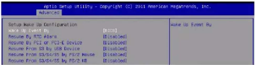
Aptio Setup Utility - Copyright (C) 2011 American Megatrends, Inc. Advanced Setup Make Up Configuration Wake Up Event By [BIDS] Resume By RTC Alarm [Disabled] Resume By PCI or PCI-E Device [Disabled] Resume From S3 by USB Device [Disabled] Resume From S3/S4/S5 by PS/2 Mouse [Disabled] Resume From S3/S4/S5 by PS/2 KB [Disabled] Wake Up Event By▶ Wake Up Event By
Setting to [BIOS] activates the following fields, and use the following fields to set the wake up events. Setting to [OS], the wake up events will be defined by OS.
▶Resume By RTC Alarm
The field is used to enable or disable the feature of booting up the system on a scheduled time/date.
▶ Date/ HH:MM:SS
If Resume By RTC Alarm is set to [Enabled], the system will automatically resume (boot up) on a specific date/hour/minute/second specified in these fields (using the <+> and <-> to select the date & time settings).
▶Resume By PCI or PCI-E Device
The item allows the activity of the PCI/PCI-E device to wake up the system.
▶Resume From S3 by USB Device
The item allows the activity of the USB device to wake up the system from S3 (Suspend to RAM) sleep state.
▶Resume From S3/S4/S5 by PS/2 Mouse/ KB
These items determine whether the system will be awakened from S3/S4/S5 state when input signal of the PS/2 mouse/ keyboard is detected.
Overclocking
text_image
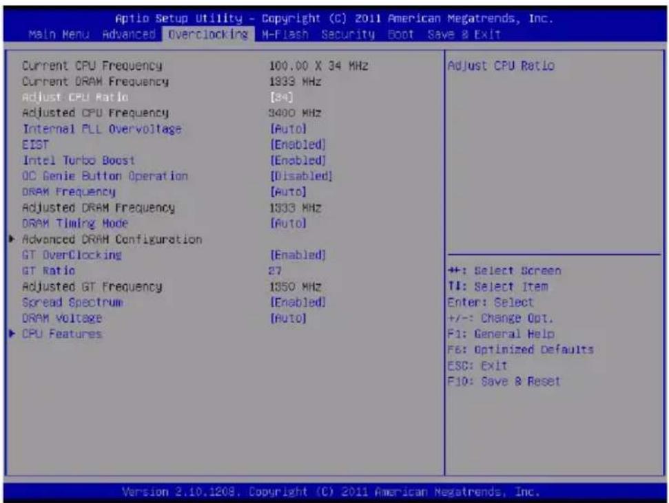
Aptio Setup Utility - Copyright (C) 2011 American Megatrends, Inc. Main Menu Advanced Overclocking M-Flash Security Boot Save & Exit Current CPU Frequency 100.00 X 34 MHz Current DRAM Frequency 1933 MHz Adjust CPU Ratio [84] Adjusted CPU Frequency 3400 MHz Internal PLL Overvoltage [Auto] EIST [Enabled] Intel Turbo Boost [Enabled] OC Genie Button Operation [Disabled] DRAM Frequency [Auto] Adjusted DRAM Frequency 1333 MHz DRAM Timing Mode [Auto] ▶ Advanced DRAM Configuration GT OverClocking [Enabled] GT Ratio 27 Adjusted GT Frequency 1350 MHz Spread Spectrum [Enabled] DRAM Voltage [Auto] ▶ CPU Features Adjust CPU Ratio ++: Select Screen TI: Select Item Enter: Select +/-: Change Opt. F1: General Help F6: Optimized Defaults ESC: Exit F10: Save & Reset Version 2.10.1209, Copyright (C) 2011 American Megatrends, Inc.▶ Current CPU / DRAM Frequency
These items show the current clocks of CPU and Memory speed. Read-only.
▶ Adjust CPU Ratio
This item controls the multiplier that is used to determine the internal clock speed of the processor relative to the external or motherboard clock speed. It is available only when the processor supports this function.
▶ Adjusted CPU Frequency
It shows the adjusted CPU frequency. Read-only.
▶ Internal PLL Overvoltage
This item are used to adjust the PLL voltage.
▶ EIST
The Enhanced Intel SpeedStep technology allows you to set the performance level of the microprocessor whether the computer is running on battery or AC power. This field will appear after you installed the CPU which supports speedstep technology.
Intel Turbo Booster
This item will appear when you install a CPU with Intel Turbo Boost technology. This item is used to enable/ disable Intel Turbo Boost technology. It can scale processor frequency higher dynamically when applications demand more performance and TDP headroom exists. It also can deliver seamless power scalability (Dynamically scale up, Speed-Step Down). It is the Intel newly technology within newly CPU.
▶ OC Genie Button Operation
This field is used to enable/ disable OC Genie function.
▶ DRAM Frequency
This setting controls the memory frequency to enable the memory to run at different frequency combinations.
▶ Adjusted DRAM Frequency
It shows the adjusted DRAM frequency. Read-only.
▶ DRAM Timing Mode
Select whether DRAM timing is controlled by the SPD (Serial Presence Detect) EE - PROM on the DRAM module. Setting to [Auto] enables DRAM timings and the following "Advanced DRAM Configuration" sub-menu to be determined by BIOS based on the configurations on the SPD. Selecting [Link] or [Unlink] allows users to configure the DRAM timings and the following related "Advanced DRAM Configuration" sub-menu manually.
▶ Advanced DRAM Configuration
Press
text_image
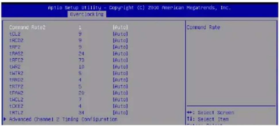
Aptio Setup Utility - Copyright (C) 2010 American Megatrends, Inc. Overclocking Command Rate2 1 [Auto] tCL2 9 [Auto] tRCD2 9 [Auto] tRF2 9 [Auto] tRAS2 24 [Auto] tRFC2 73 [Auto] tWR2 10 [Auto] tWTR2 5 [Auto] tRRD2 4 [Auto] tRTP2 5 [Auto] tFAN2 20 [Auto] tWCL2 7 [Auto] tCKE2 4 [Auto] tRTL2 34 [Auto] ► Advanced Channel 2 Timing Configuration Command Rate +: Select Screen TL: Select Item▶ Command Rate
This setting controls the DRAM command rate.
▶ tCL
This controls the CAS latency, which determines the timing delay (in clock cycles) before SDRAM starts a read command after receiving it.
▶ tRCD
When DRAM is refreshed, both rows and columns are addressed separately. This setup item allows you to determine the timing of the transition from RAS (row address strobe) to CAS (column address strobe). The less the clock cycles, the faster the DRAM performance.
▶ tRP
This setting controls the number of cycles for Row Address Strobe (RAS) to be allowed to precharge. If insufficient time is allowed for the RAS to accumulate its charge before DRAM refresh, refreshing may be incomplete and DRAM may fail to retain data. This item applies only when synchronous DRAM is installed in the system.
▶ tRAS
This setting determines the time RAS takes to read from and write to memory cell.
▶ tRFC
This setting determines the time RFC takes to read from and write to a memory cell.
▶ tWR
Minimum time interval between end of write data burst and the start of a precharge command. Allows sense amplifiers to restore data to cells.
▶ tWTR
Minimum time interval between the end of write data burst and the start of a column-read command. It allows I/O gating to overdrive sense amplifiers before read command starts.
▶ tRRD
Specifies the active-to-active delay of different banks.
▶ tRTP
Time interval between a read and a precharge command.
▶ tFAW
This item is used to set the tFAW (four activate window delay) timing.
▶ tWCL
This item is used to set the tWCL (Write CAS Latency) timing.
▶tCKE
This item is used to set the tCKE timing.
▶ tRTL
This item is used to set the tRTL timing.
▶ Advanced Channel 1/2 Timing Configuration
Press
▶ GT OverClocking
This item allows you to enable/ disable the overclocking of integrated graphics.
▶ GT Ratio
This setting controls the ratio of integrated graphics frequency to enable the integrated graphics to run at different frequency combinations.
▶ Adjusted GT Frequency
It shows the adjusted integrated graphics frequency. Read-only.
▶ Spread Spectrum
When the mainboard's clock generator pulses, the extreme values (spikes) of the pulses create EMI (Electromagnetic Interference). The Spread Spectrum function reduces the EMI generated by modulating the pulses so that the spikes of the pulses are reduced to flatter curves.
Important
- If you do not have any EMI problem, leave the setting at [Disabled] for optimal system stability and performance. But if you are plagued by EMI, select the value of Spread Spectrum for EMI reduction.
- The greater the Spread Spectrum value is, the greater the EMI is reduced, and the system will become less stable. For the most suitable Spread Spectrum value, please consult your local EMI regulation.
- Remember to disable Spread Spectrum if you are overclocking because even a slight jitter can introduce a temporary boost in clock speed which may just cause your over clocked processor to lock up.
▶ DRAM Voltage
This item is used to adjust the memory voltage.
▶ CPU Features
Press
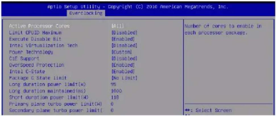
text_image
Aptio Setup Utility - Copyright (C) 2010 American Megatrends, Inc. Overclocking Active Processor Cores Limit CPUID Maximum Execute Disable Bit Intel Virtualization Tech Power Technology CIE Support OverSpeed Protection Intel C-State Package C State limit Long duration power limit(N) Long duration maintained(ms) Short duration power limit(H) Primary plane turbo power limit(W) Secondary plane turbo power limit( 0 Number of cores to enable in each processor package. +: Select Screen▶Active Processor Cores
This item allows you to select the number of active processor cores.
▶ Limit CPUID Maximum
It is designed to limit the listed speed of the processor to older operating systems.
▶ Execute Disable Bit
Intel's Execute Disable Bit functionality can prevent certain classes of malicious "buffer overflow" attacks when combined with a supporting operating system. This functionality allows the processor to classify areas in memory by where application code can execute and where it cannot. When a malicious worm attempts to insert code in the buffer, the processor disables code execution, preventing damage or worm propagation.
▶Intel Virtualization Tech
This item is used to enable/disable the Intel Virtualization technology. For further information please refer to Intel's official website.
▶ Power Technology
This item allows you to select the Intel Dynamic Power technology mode.
▶ C1E Support
To enable this item to read the CPU power consumption while idle. Not all processors support Enhanced Halt state (C1E).
▶OverSpeed Protection
Overspeed Protection function can monitor the current CPU draws as well as its power consumption. If it exceeds a certain level, the processor automatically reduces its clock speed. If you want to overclock your CPU, set it to [Disabled].
Intel C-State
C-state is a power management state that significantly reduces the power of the processor during idle. This field will appear after you installed the CPU which supports c-state technology.
▶Package C State limit
This field allows you to select a C-state limit.
▶Long duration power limit(W)
This field allows you to adjust the TDP power limit for the long duration.
▶Long duration maintained(ms)
This field allows you to adjust the maintaining time for long duration power limit.
▶ Short duration power limit(W)
This field allows you to adjust the TDP power limit for the short duration.
▶ Primary/ Secondary plane turbo power limit (W)
These fields allow you to adjust the TDP limit for the primary/ secondary plane tur - bo.
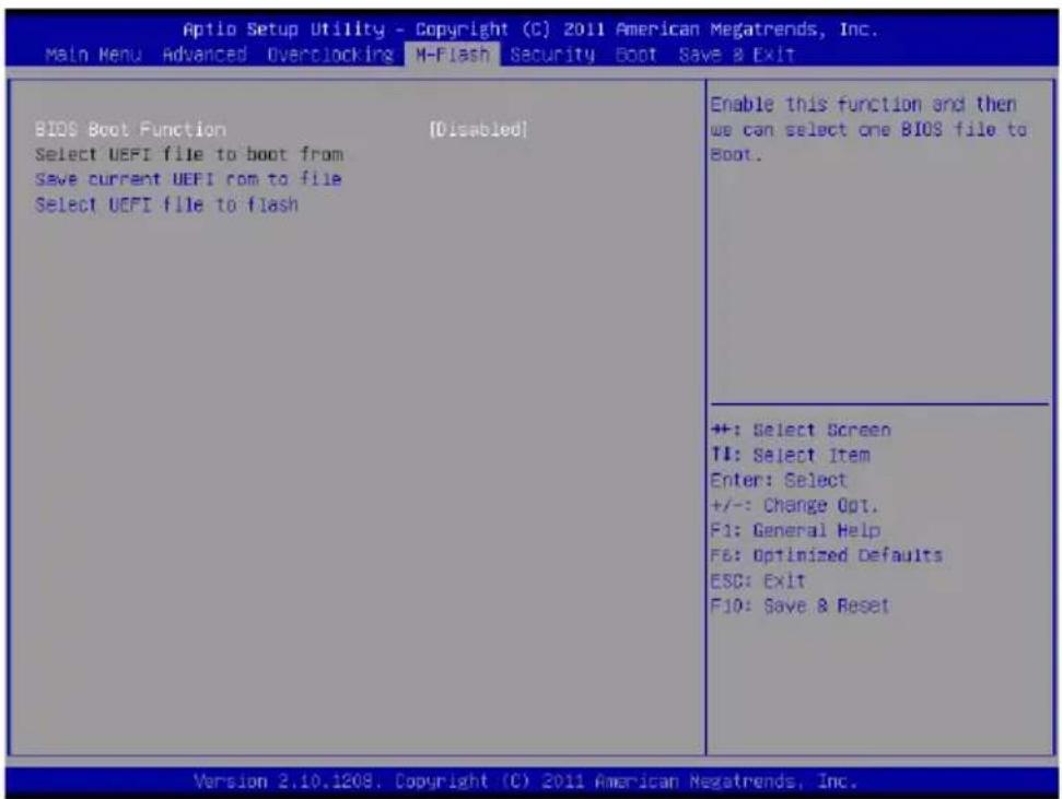
M-Flash
text_image
Aptio Setup Utility - Copyright (C) 2011 American Megatrends, Inc. Main Menu Advanced Overclocking M-Flash Security Boot Save & Exit BIDS Boot Function [Disabled] Select UEFI file to boot from Save current UEFI com to file Select UEFI file to flash Enable this function and then we can select one BIOS file to Boot. ++: Select Screen T#: Select Item Enter: Select +/-: Change Opt. F1: General Help F6: Optimized Defaults ESC: Exit F10: Save & Reset Version 2.10.1209, Copyright (C) 2011 American Megatrends, Inc.▶ BIOS Boot Function
This allows you to enable/ disable the system to boot from the BIOS file inside USB drive (FAT/ 32 format only).
▶ Select UEFI file to boot from
When the BIOS Boot function as sets to [Enabled], this item is selectable. This item allows to select particular BIOS file from the USB/ Storage (FAT/ 32 format only) drive. And the system will boot from selected BIOS file.
▶ Save current UEFI rom to file
Please setup a specific folder in specific USB/ Storage drive to save BIOS file from BIOS ROM chip data. Note: it only supports FAT/ 32 file system drive.
▶ Select UEFI file to flash
This item allows you to select particular BIOS file from the USB/ Storage (FAT/ 32 for - mat only) drive for updating BIOS.
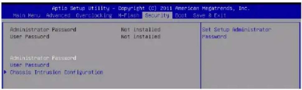
Security
text_image
Aptio Setup Utility - Copyright (C) 2011 American Megatrends, Inc. Main Menu Advanced Overclocking M-Flash Security Boot Save & Exit Administrator Password Not installed User Password Not installed Administrator Password User Password ▶ Chassis Intrusion Configuration Set Setup Administrator Password▶ Administrator Password
This item is used to set the administrator password. When a administrator password has been set, you will be prompted to enter it every time you try to enter BIOS Setup.
▶ User Password
This item is used to set the user password. When a user password has been set, you will be prompted to enter it every time you try to enter the operating system.
Important
When you select the Administrator Password / User Password item, a password box will appear on the screen. Type the password, and press
To clear a set password, just press
These two items prevent an unauthorized person from changing any part of your system configuration.
▶ Chassis Intrusion Configuration
Press
▶ Chassis Intrusion
This item enables or disables the feature of recording the chassis intrusion status and issuing a warning message if the chassis is once opened. To clear the warning message, set the field to [Reset]. The setting of the field will automatically return to [Enabled] later.
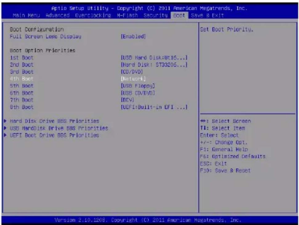
Boot
text_image
Aptio Setup Utility - Copyright (C) 2011 American Megatrends, Inc. Main Menu Advanced Overclocking M-Flash Security Boot Save & Exit Boot Configuration Full Screen Logo Display [Enabled] Boot Option Priorities 1st Boot [USB Hard Disk:Ut16...] 2nd Boot [Hard Disk: ST33206...] 3rd Boot [CO/DVD] 4th Boot [Network] 5th Boot [USB Floppy] 6th Boot [USB CD/DVD] 7th Boot [BEV] 8th Boot [UEFI:Built-in EFI ...] ► Hard Disk Drive BBS Priorities ► USB HardDisk Drive BBS Priorities ► UEFI Boot Drive BBS Priorities Set Boot Priority. ++: Select Screen TI: Select Item Enter: Select +/-: Change Opt. F1: General Help F6: Optimized Defaults ESC: Exit F10: Save & Reset Version 2.10.1209, Copyright (C) 2011 American Megatrends, Inc.▶ Full Screen Logo Display
This item enables this system to show the company logo on the boot-up screen. Settings are:
[Enabled] Shows a still image (logo) on the full screen at boot.
[Disabled] Shows the POST messages at boot.
== Set Boot Priority ==
▶ 1st\~8th Boot
You can select the boot priorities in these Boot Option items.
▶ Hard Disk/ USB HardDisk/ UEFI Boot Drive BBS Priorities
▶ Boot Option
You can select the hard disk/ USB hard disk/ UEFI Boot priorities in these Boot Option items.
Save & Exit
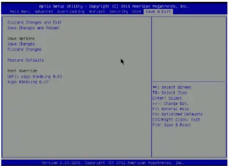
text_image
Aptio Setup Utility - Copyright (C) 2011 American Megatrends, Inc. Main Menu Advanced Overclocking M-Flash Security Boot Save & Exit Discard Changes and Exit Save Changes and Reboot Save Options Save Changes Discard Changes Restore Defaults Boot Override UEFI: aigo Miniking 8.07 aigo Miniking 8.07 +: Select Screen TI: Select Item Enter: Select +/-: Change Opt. F1: General Help F6: Optimized Defaults ESC/Righth Click: Exit F10: Save & Reset Version 2.10.1208, Copyright (C) 2011 American Megatrends, Inc.▶ Discard Changes and Exit
Use this item to abandon all changes and exit setup.
▶ Save Changes and Reboot
Use this item to save changes and reboot the system.
▶ Save Changes
Use this item to save changes.
▶ Discard Changes
Use this item to abandon all changes.
▶ Restore Defaults
Use this item to load the optimized default values set by the BIOS vendor.
== Boot Override ==
The installed storage devices will appear on this menu, you can select one of them be a boot device.

natural_image
Abstract illustration of a globe with orbiting lines and floating elements (no text or symbols)Appendix A
Realtek Audio
The Realtek audio provides 10-channel DAC that simultaneously supports 7.1 sound playback and 2 channels of independent stereo sound output (multiple streaming) through the Front-Out-Left and Front-Out-Right channels.
Installing the Realtek HD Audio Driver
You need to install the HD audio driver for Realtek audio codec to function properly before you can get access to 2-, 4-, 6-, 8- channel or 7.1+2 channel audio operations. Follow the procedures described below to install the drivers for different operating systems.
Installation for Windows®
For Windows® XP, you must install Windows® XP Service Pack3 or later before installing the driver.
The following illustrations are based on Windows®7 environment and could look slightly different if you install the drivers in different operating systems.
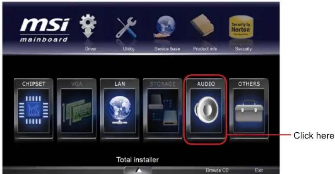
- Insert the application DVD into the DVD-ROM drive. The setup screen will automatically appear.
- Click Driver tab.
- Click AUDIO button.
text_image
msi mainboard Driver Utility Service base Product info Security CHIPSET VGA LAN STORAGE AUDIO OTHERS Click here Total installer Browse CD Exit- Select Realtek HD Audio Drivers to start installing the drivers.
- Click Next to install the Realtek High Definition Audio Driver.
- Follow the on-screen instructions to install drivers.
- Click Finish to restart the system.
Important
The HD Audio Configuration software utility is under continuous update to enhance audio applications. Hence, the program screens shown here in this section may be slightly different from the latest software utility and shall be held for reference only.
Software Configuration
After installing the audio driver, the "Realtek HD Audio Manager" icon will appear at the notification area (lower right of the screen). You may double click the icon and the GUI will pop up accordingly.

text_image
Double click the icon Customize...It is also available to enable the audio driver by clicking the Realtek HD Audio Manager from the Control Panel.
Software panel overview
The following figure describes the function of the Realtek HD Audio Manager panel.
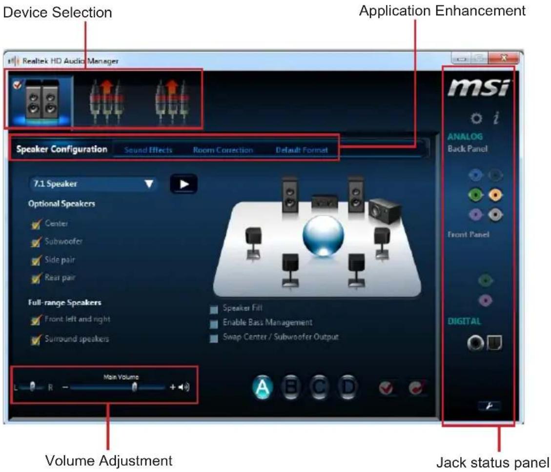
text_image
Device Selection Realtek HD Audio Manager Application Enhancement Speaker Configuration Sound Effects Room Correction Default Format 7.1 Speaker Optional Speakers Center Subwoofer Side pair Rear pair Full-range Speakers Front left and right Surround speakers Speaker Fill Enable Bass Management Swap Center / Subwoofer Output Main Volume Volume Adjustment Jack status panel■ Device Selection
Here you can select a audio output source to change the related options. The "check" sign (in orange) indicates the devices as default.
■ Volume Adjustment
You can control the volume or balance the right/left side of the speakers that you plugged in front or rear panel by adjust the bar.
■ Application Enhancement
The array of options will provide you a complete guidance of anticipated sound effect for both output and input device.
■ Jack status panel
This panel depicts all render and capture devices currently connected with your computer.
Auto popup dialog
When you plug into the device at the jack, a dialogue window will pop up asking you which device is current connected.
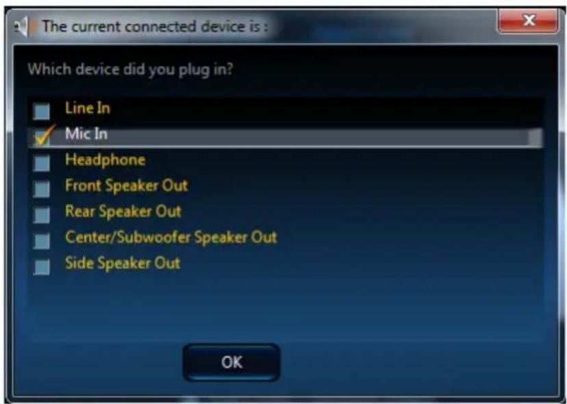
text_image
The current connected device is : Which device did you plug in? Line In Mic In Headphone Front Speaker Out Rear Speaker Out Center/Subwoofer Speaker Out Side Speaker Out OKAs you know, each jack corresponds to its default setting, you can refer to the next section "Hardware Default Setting".
Hardware Default Setting
The following diagrams are audio back panel default setting.
■ Backpanel audio jacks to 2-channel speakers diagram
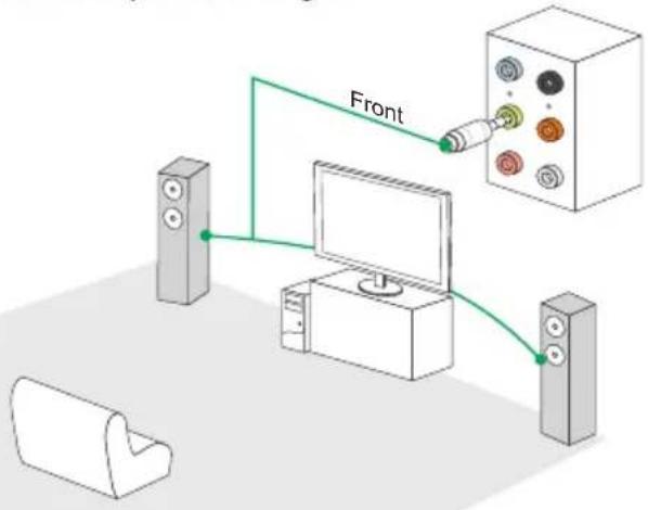
text_image
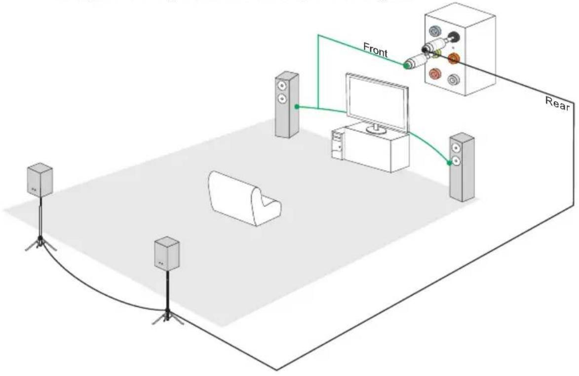
Front■ Backpanel audio jacks to 4-channel speakers diagram
flowchart
graph TD
    A["Front"] --> B["Screen"]
    B --> C["Rear"]
    D["Camera"] --> E["Speaker"]
    F["Speaker"] --> G["Monitor"]
    H["Speaker"] --> I["Monitor"]
    J["Speaker"] --> K["Monitor"]
    style A fill:#f9f,stroke:#333
    style F fill:#f9f,stroke:#333
    style D fill:#ccf,stroke:#333
    style E fill:#ccf,stroke:#333
    style G fill:#ccf,stroke:#333
    style H fill:#ccf,stroke:#333
    style I fill:#ccf,stroke:#333
    style J fill:#ccf,stroke:#333
    style K fill:#ccf,stroke:#333
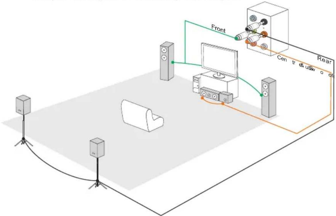
■ Backpanel audio jacks to 6-channel speakers diagram
flowchart
graph TD
    A["Speaker"] --> B["Central Display"]
    C["Speaker"] --> B
    D["Speaker"] --> B
    B --> E["Rear"]
    style A fill:#f9f,stroke:#333
    style C fill:#f9f,stroke:#333
    style D fill:#f9f,stroke:#333
    style E fill:#ccf,stroke:#333
■ Backpanel audio jacks to 8-channel speakers diagram

flowchart
graph TD
    A["Speaker"] --> B["Front"]
    B --> C["Central Monitor"]
    C --> D["Rear"]
    D --> E["Side Surround"]
    style A fill:#f9f,stroke:#333
    style B fill:#ccf,stroke:#333
    style C fill:#cfc,stroke:#333
    style D fill:#fcc,stroke:#333
    style E fill:#ffc,stroke:#333