
UR-80 - Multitrack recorder ROLAND - Free user manual and instructions
Find the device manual for free UR-80 ROLAND in PDF.

User questions about UR-80 ROLAND
0 question about this device. Answer the ones you know or ask your own.
Ask a new question about this device
Download the instructions for your Multitrack recorder in PDF format for free! Find your manual UR-80 - ROLAND and take your electronic device back in hand. On this page are published all the documents necessary for the use of your device. UR-80 by ROLAND.
USER MANUAL UR-80 ROLAND
Thank you for purchasing the USB Recording System UR-80.
Before using this unit, carefully read the sections entitled: "USING THE UNIT SAFELY" and "IMPORTANT NOTES" (OWNER'S MANUAL pp. 2-4). These sections provide important information concerning the proper operation of the unit. Additionally, in order to feel assured that you have gained a good grasp of every feature provided by your new unit, Owner's manual should be read in its entirety. The manual should be saved and kept on hand as a convenient reference.
USING THE UNIT SAFELY
INSTRUCTIONS FOR THE PREVENTION OF FIRE, ELECTRIC SHOCK, OR INJURY TO PERSONS
About WARNING and CAUTION Notices
| ▲WARNING | Used for instructions intended to alert the user to the risk of death or severe injury should the unit be used improperly. |
| ▲CAUTION | Used for instructions intended to alert the user to the risk of injury or material damage should the unit be used improperly. * Material damage refers to damage or other adverse effects caused with respect to the home and all its furnishings, as well to domestic animals or pets. |
About the Symbols
| △ | The △ symbol alerts the user to important instructions or warnings. The specific meaning of the symbol is determined by the design contained within the triangle. In the case of the symbol at left, it is used for general cautions, warnings, or alerts to danger. |
| ◎ | The ⊙ symbol alerts the user to items that must never be carried out (are forbidden). The specific thing that must not be done is indicated by the design contained within the circle. In the case of the symbol at left, it means that the unit must never be disassembled. |
| ◆ | The ● symbol alerts the user to things that must be carried out. The specific thing that must be done is indicated by the design contained within the circle. In the case of the symbol at left, it means that the power-cord plug must be unplugged from the outlet. |
ALWAYS OBSERVE THE FOLLOWING
WARNING
Before using this unit, make sure to read the instructions below, and the Owner's Manual.

- Do not open (or modify in any way) the unit or its AC adaptor.

- Do not attempt to repair the unit, or replace parts within it (except when this manual provides specific instructions directing you to do so). Refer all servicing to your retailer, the nearest Roland Service Center, or an authorized Roland distributor, as listed on the "Information" page.

- Never use or store the unit in places that are:


- Subject to temperature extremes (e.g., direct sunlight in an enclosed vehicle, near a heating duct, on top of heat-generating equipment); or are
- Damp (e.g., baths, washrooms, on wet floors); or are
- Humid; or are
- Exposed to rain; or are
- Dusty; or are
-
Subject to high levels of vibration.
-
Make sure you always have the unit placed so it is level and sure to remain stable. Never place it on stands that could wobble, or on inclined surfaces.

WARNING
- Be sure to use only the AC adaptor supplied with the unit. Also, make sure the line voltage at the installation matches the input voltage specified on the AC adaptor's body. Other AC adaptors may use a different polarity, or be designed for a different voltage, so their use could result in damage, malfunction, or electric shock.

- Do not excessively twist or bend the power cord, nor place heavy objects on it. Doing so can damage the cord, producing severed elements and short circuits. Damaged cords are fire and shock hazards!

- This unit, either alone or in combination with an amplifier and headphones or speakers, may be capable of producing sound levels that could cause permanent hearing loss. Do not operate for a long period of time at a high volume level, or at a level that is uncomfortable. If you experience any hearing loss or ringing in the ears, you should immediately stop using the unit, and consult an au ogist.

- Do not allow any objects (e.g., flammable material, coins, pins); or liquids of any kind (water, soft drinks, etc.) to penetrate the unit.


WARNING
-
Immediately turn the power off, remove the AC adaptor from the outlet, and request servicing by your retailer, the nearest Roland Service Center, or an authorized Roland distributor, as listed on the "Information" page when:
-
The AC adaptor or the power-supply cord has been damaged; or
- If smoke or unusual odor occurs
- Objects have fallen into, or liquid has been spilled onto the unit; or
- The unit has been exposed to rain (or otherwise has become wet); or
-
The unit does not appear to operate normally or exhibits a marked change in performance.
-
In households with small children, an adult should provide supervision until the child is capable of following all the rules essential for the safe operation of the unit.

- Protect the unit from strong impact. (Do not drop it!)

- Do not force the unit's power-supply cord to share an outlet with an unreasonable number of other devices. Be especially careful when using extension cords—the total power used by all devices you have connected to the extension cord's outlet must never exceed the power rating (watts/amperes) for the extension cord. Excessive loads can cause the insulation on the cord to heat up and eventually melt through.

Before using the unit in a foreign country, consult with your retailer, the nearest Roland Service Center, or an authorized Roland distributor, as listed on the "Information" page.

DO NOT play a CD-ROM disc on a conventional audio CD player. The resulting sound may be of a level that could cause permanent hearing loss. Damage to speakers or other system components may result.

| Caution | |
| · The unit and the AC adaptor should be located so their location or position does not interfere with their proper ventilation. | ! |
| · Always grasp only the output plug or the body of the AC adaptor when plugging into, or unplugging from, this unit or an outlet. | ! |
| · At regular intervals, you should unplug the AC adaptor and clean it by using a dry cloth to wipe all dust and other accumulations away from its prongs. Also, disconnect the power plug from the power outlet whenever the unit is to remain unused for an extended period of time. Any accumulation of dust between the power plug and the power outlet can result in poor insulation and lead to fire. | ! |
| · Try to prevent cords and cables from becoming entangled. Also, all cords and cables should be placed so they are out of the reach of children. | ! |
| · Never climb on top of, nor place heavy objects on the unit. | ! |
| · Never handle the AC adaptor body, or its output plugs, with wet hands when plugging into, or unplugging from, an outlet or this unit. | ! |
| · Before moving the unit, disconnect the AC adaptor and all cords coming from external devices. | ! |
| · Before cleaning the unit, turn off the power and unplug the AC adaptor from the outlet. | ! |
| · Whenever you suspect the possibility of lightning in your area, disconnect the AC adaptor from the outlet. | ! |
| · Should you remove the optical connector caps, make sure to put them in a safe place out of children's reach, so there is no chance of them being swallowed accidentally. | ! |
| · Always turn the phantom power off when connecting any device other than condenser microphones that require phantom power. You risk causing damage if you mistakenly supply phantom power to dynamic microphones, audio playback devices, or other devices that don't require such power. Be sure to check the specifications of any microphone you intend to use by referring to the manual that came with it. | ! |
| This instrument's phantom power: DC 48 V DC, 10 mA Max) | |
IMPORTANT NOTES
In addition to the items listed under "USING THE UNIT SAFELY" on page 2, please read and observe the following:
Power Supply
- Do not use this unit on the same power circuit with any device that will generate line noise (such as an electric motor or variable lighting system).
- The AC adaptor will begin to generate heat after long hours of consecutive use. This is normal, and is not a cause for concern.
- Before connecting this unit to other devices, turn off the power to all units. This will help prevent malfunctions and/or damage to speakers or other devices.
Placement
- Using the unit near power amplifiers (or other equipment containing large power transformers) may induce hum. To alleviate the problem, change the orientation of this unit; or move it farther away from the source of interference.
- This device may interfere with radio and television reception. Do not use this device in the vicinity of such receivers.
- Noise may be produced if wireless communications devices, such as cell phones, are operated in the vicinity of this unit. Such noise could occur when receiving or initiating a call, or while conversing. Should you experience such problems, you should relocate such wireless devices so they are at a greater distance from this unit, or switch them off.
- Do not expose the unit to direct sunlight, place it near devices that radiate heat, leave it inside an enclosed vehicle, or otherwise subject it to temperature extremes. Excessive heat can deform or discolor the unit.
- When moved from one location to another where the temperature and/or humidity is very different, water droplets (condensation) may form inside the unit. Damage or malfunction may result if you attempt to use the unit in this condition. Therefore, before using the unit, you must allow it to stand for several hours, until the condensation has completely evaporated.
Maintenance
- For everyday cleaning wipe the unit with a soft, dry cloth or one that has been slightly dampened with water. To remove stubborn dirt, use a cloth impregnated with a mild, non-abrasive detergent. Afterwards, be sure to wipe the unit thoroughly with a soft, dry cloth.
- Never use benzine, thinners, alcohol or solvents of any kind, to avoid the possibility of discoloration and/or deformation.
Repairs and Data
- Please be aware that all data contained in the unit's memory may be lost when the unit is sent for repairs. Important data should always be backed up in another MIDI device (e.g., a sequencer), or written down on paper (when possible). During repairs, due care is taken to avoid the loss of data. However, in certain cases (such as when circuitry related to memory itself is out of order), we regret that it may not be possible to restore the data, and Roland assumes no liability concerning such loss of data.
Additional Precautions
- Please be aware that the contents of memory can be irretrievably lost as a result of a malfunction, or the improper operation of the unit. To protect yourself against the risk of loosing important data, we recommend that you periodically save a backup copy of important data you have stored in the unit's memory in another MIDI device (e.g., a sequencer)
- Unfortunately, it may be impossible to restore the contents of data that was stored in another MIDI device (e.g., a sequencer) once it has been lost. Roland Corporation assumes no liability concerning such loss of data.
- Use a reasonable amount of care when using the unit's buttons, sliders, or other controls; and when using its jacks and connectors. Rough handling can lead to malfunctions.
- When connecting / disconnecting all cables, grasp the connector itself—never pull on the cable. This way you will avoid causing shorts, or damage to the cable's internal elements.
- To avoid disturbing your neighbors, try to keep the unit's volume at reasonable levels. You may prefer to use headphones, so you do not need to be concerned about those around you (especially when it is late at night).
-
When you need to transport the unit, package it in the box (including padding) that it came in, if possible. Otherwise, you will need to use equivalent packaging materials.
-
Use a cable from Roland to make the connection. If using some other make of connection cable, please note the following precautions.
- Some connection cables contain resistors. Do not use cables that incorporate resistors for connecting to this unit. The use of such cables can cause the sound level to be extremely low, or impossible to hear. For information on cable specifications, contact the manufacturer of the cable.
- Before you open the included CD-ROM, you must read the "license agreement." Opening the CD-ROM will be taken to mean your acceptance of the license agreement.
Handling CD-ROMs
- Avoid touching or scratching the shiny underside (encoded surface) of the disc. Damaged or dirty CD-ROM discs may not be read properly. Keep your discs clean using a commercially available CD cleaner.
Copyright
- Unauthorized recording, distribution, sale, lending, public performance, broadcasting, or the like, in whole or in part, of a work (musical composition, video, broadcast, public performance, or the like) whose copyright is held by a third party is prohibited by law.
- When exchanging audio signals through a digital connection with an external instrument, this unit can perform recording without being subject to the restrictions of the Serial Copy Management System (SCMS). This is because the unit is intended solely for musical production, and is designed not to be subject to restrictions as long as it is used to record works (such as your own compositions) that do not infringe on the copyrights of others. (SCMS is a feature that prohibits second-generation and later copying through a digital connection. It is built into MD recorders and other consumer digital-audio equipment as a copyright-protection feature.)
-
Do not use this unit for purposes that could infringe on a copyright held by a third party. We assume no responsibility whatsoever with regard to any infringements of third-party copyrights arising through your use of this unit.
-
Microsoft and Windows are registered trademarks of Microsoft Corporation.
- Screen shots in this documents are reprinted with permission from Microsoft Corporation.
- Windows® is known officially as: "Microsoft® Windows® operating system."
- Apple and Macintosh are registered trademark of Apple Computer, Inc.
- MacOS is a trademark of Apple Computer, Inc.
- All product names mentioned in this document are trademarks or registered trademarks of their respective owners.
- OMS is a registered trademark of Opcode Systems, Inc.
- FreeMIDI is a trademark of Mark of the Unicorn, Inc.
- VST is a trademark of Steinberg Media Technologies AG.
Contents
IMPORTANT NOTES 4
Contents 6
Main Features of the UR-80 16
Names of Things and What They Do. 17
Main panel 17
Track Control section 18
Master Control section 21
Audio Control section 23
Rear panel. 24
Side panel 26
Basic operation 27
Basic connections and settings 28
Basic connections 28
MIDI flow 28
Audio flow (block diagram) 29
Input/output devices 30
Two MIDI ports 31
Controlling your software 32
Switching memory sets 32
SONAR 33
Settings in SONAR 33
Functions assigned to the controllers 34
Cubase SX. 36
Settings in Cubase SX. 36
Functions assigned to the controllers 37
Cubase VST 39
Settings in Cubase VST (Windows users) 39
Settings in Cubase VST (Macintosh users) 40
Functions assigned to the controllers 41
Logic 43
Settings in Logic 43
Functions assigned to the controllers 44
Pro Tools LE, Digital Performer 3. 47
Settings in ProTools LE 47
Settings in Digital Performer 47
Functions assigned to the controllers 48
Reason. 51
MIDI port settings 51
Settings for reason transport and MIDI IN DEVICE 51
Controlling the tempo of the song 52
MIDI Remote Mapping settings 52
Functions assigned to the controllers 53
Roland MCR-8 compatible applications 55
Recording audio. 57
Basic use 57
Recording guitar or bass 58
Recording from a mic 59
Recording a keyboard 60
Recording from an audio device 61
Digitally recording from a CD/MD/DAT 62
Recording the output of the UR-80 on a digital device 63
Adjusting the audio latency 64
Using ASIO Direct Monitor. 65
Advanced operation 67
Synth Edit mode 68
Track faders 68
Assign button (ASSIGN) 68
Track control knobs (TRACK/HQ CONTROL) 69
Track group select button (TRACK GROUP) 69
Track status buttons (TRACK STATUS/HQ PART) 69
Parameter list. 70
V-LINK mode 71
Parameter list. 71
Controllers used in V-LINK mode 72
UR-80 Editor 73
Starting up UR-80 Editor 73
MIDI Port settings. 74
UR-80 Editor window 75
Main window 75
Controller settings. 77
MIDI messages that you can assign to controllers. 77
Assigning a MIDI message 78
Checking the assigned MIDI messages 79
Memory Set Initial Message 80
Specifying the Memory Set Initial Message 80
Enabling the Memory Set Initial Message 80
Exchanging data with the UR-80 81
Transmitting to the UR-80 81
Receiving from the UR-80 81
Saving or loading in SMF format. 82
Saving a memory set in SMF format. 82
Loading a memory set from a SMF file 82
System settings 82
Pro Tools LE, Digital Performer 3. 113
Section Track Control 150
Section Master Control. 153
Section Audio Control 155
Face arriere 156
Face latérale. 158
Pro Tools LE, Digital Performer 3. 179
Pro Tools LE, Digital Performer 3. 245
Pro Tools LE, Digital Performer 3. 311
System-related settings 348
Restoring the factory settings (Factory Reset) 348
Switching the Driver Mode 348
Memory sets 349
PRESET MEMORY (SONAR) PARAMETER LIST 349
USR1 MEMORY (Cubase SX) PARAMETER LIST 352
USR2 MEMORY (Cubase VST) PARAMETER LIST 355
USR3 MEMORY (Logic) PARAMETER LIST 358
USR4 MEMORY (Pro Tools LE / Digital Performer) PARAMETER LIST 361
USR5 MEMORY (Reason) PARAMETER LIST 365
USR6 MCR-8 Mode4-A/1-8 PARAMETER LIST 368
USR7 MCR-8 Mode4-B/9-16 PARAMETER LIST 370
Troubleshooting 372
Can't use the START/STOP button to make Reason play/stop 372
When using Logic, can't use the track control knobs to edit parameters....372
Can't control Hyper Canvas (or your MIDI sound module) in Synth Edit mode 373
Can only control a specific Part of Hyper Canvas (or your MIDI sound module) in Synth Edit mode 373
Operating system becomes unstable 373
Can't hear sound from the computer 373
Can't record/play MIDI. 374
Sound from devices connected to the input jack is not heard in the headphones. 374
Volume from a device connected to the input jacks is too low. 374
The sound of a device connected to the input jack is distorted. 374
Noise is heard during audio playback 375
Sound is interrupted during audio playback 376
Digitally recorded sound is distorted, is at the wrong pitch, or-containing noise 378
Playback or recording halts midway through, and then becomes impossible 378
Recording produces a silent (blank) file 378
A loud buzz is present in the guitar signal 378
MIDI implementation 379
Specifications 386
UR-80: USB Recording System 386
Index 387
Main Features of the UR-80
The UR-80 combines two major types of functionality; a Controller that uses MIDI messages to control your sequencer software or synthesizer, and a USB Audio Interface that lets you record and play back audio on your computer.
It is the ideal partner for your DAW (Digital Audio Workstation) software, and will let you perform music production operations such as recording, playback, and mixing faster and more efficiently.
Fully assignable design
The UR-80 is fully assignable. You can assign any type of MIDI message—control changes, RPN, NRPN, system exclusive—to the controllers. Using the dedicated UR-80 Editor software you can freely change the MIDI message assignments. Customized assignments can be stored in the UR-80's seven user memory sets.
USB interface with 24-bit/96 kHz support
The audio interface is designed for high audio quality, and supports up to 24-bit/96 kHz. XLR jacks, mic preamps, and phantom power are provided, allowing you to use condenser mics for serious recording.
A high-impedance switch lets you connect a guitar directly, and both optical and coaxial type digital input/output jacks are provided.
Comes with "Hyper Canvas" software synthesizer
The GM2-compatible Hyper Canvas software synthesizer is included, providing 256 sounds + 9 drum sets. You can use it in conjunction with your DXi- or VSTi-compatible software to start producing music immediately.
MIDI interface functionality
The UR-80 includes a USB MIDI interface with FPT support. Even when the UR-80 is not connected to your computer via USB, you can use it as a MIDI controller via its MIDI connectors.
V-LINK support
The UR-80 supports V-LINK, and can be used in conjunction with video devices such as the Edirol DV-7PR for video-integrated performances.
Names of Things and What They Do
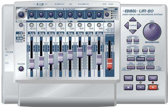
Main panel
The UR-80's main panel is divided into the Track Control section, Master Control section, and Audio Control section.
The Track Control section and Master Control section provide 43 controllers to which you can assign MIDI messages. By using these controllers in conjunction with the SHIFT button, and including assignments to LEDs, you can assign a total of 136 different MIDI messages. Use UR-80 Editor to assign MIDI messages to controllers and to edit the assignments. UR-80 Editor is provided on the included CD-ROM.
- For details on UR-80 Editor, refer to "UR-80 Editor (p. 73)".
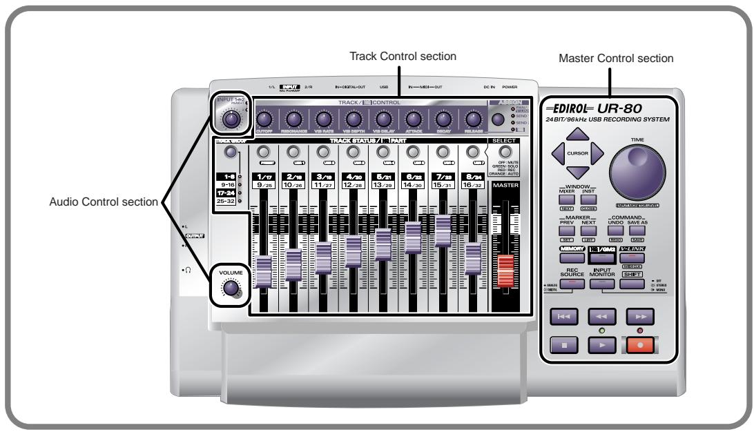
- Track Control section .....p. 18
- Master Control section. p. 21
Audio Control section. p. 23

An indication of Assignable for a controller in the explanations that follow means that you can assign a MIDI message to this controller.
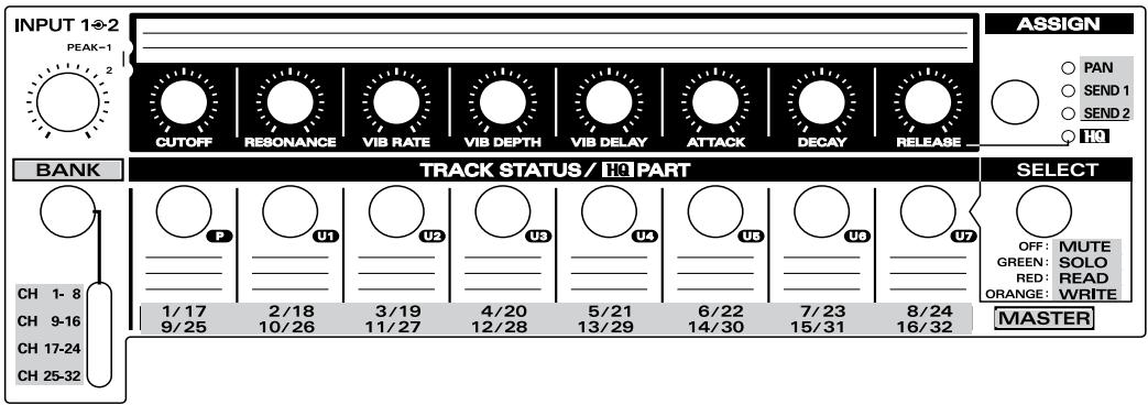
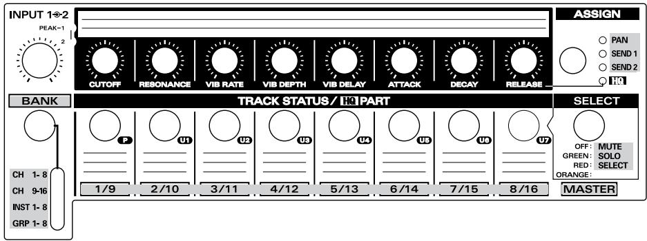
Track Control section
The Track Control section lets you control the track parameters of your sequencer software. In addition to volume and pan, you can also control parameters such as track status and effect send level. By switching track groups you can control the parameters of up to 32 tracks.
- The content that will actually be controlled will depend on the software you are using.

Synth Edit mode or V-LINK mode, the UR-80 will operate differently than explained here. For details, refer to "Synth Edit mode (p. 68)" or "V-LINK mode (p. 71)".
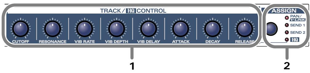
1. Track Control knobs (TRACK/HQ CONTROL) Assignable
You can assign MIDI messages to each of these eight knobs. Three different messages can be assigned to each knob; one for each state of the Assign button (PAN, SEND 1, SEND 2). This means that you can assign a total of 24 different messages to the Track Control knobs. Typically, you will use these to control track panning or effect send on your sequencer software.
2. Assign button (ASSIGN)
This button switches the messages that are assigned to the track control knobs. By pressing the Assign button you can select from these choices: PAN SEND 1 SEND 2.
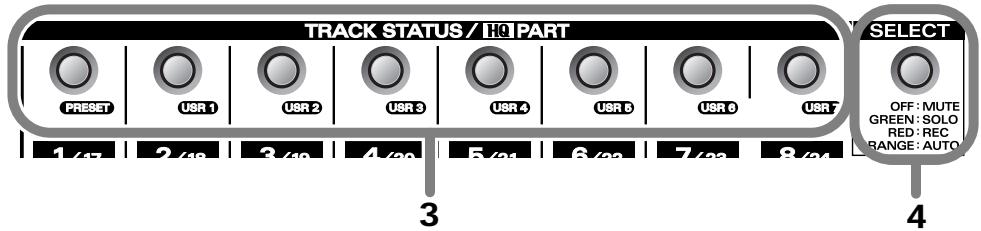
3. Track Status buttons (TRACK STATUS/HQ PART)
Assignable
You can assign MIDI messages to each of these eight buttons. You can also assign MIDI messages to the LED of each button, and turn the LEDs on/off from your sequencer software.
To each button and LED you can assign four different messages; one for each state of the Select button (off, green, red, orange). This means that you can assign a total of 32 MIDI messages to the Track Status buttons, and 32 MIDI messages to the LEDs.
Typically, you will use these buttons to switch the track status (e.g., mute, solo) on your sequencer software.
4. Select button (SELECT)
This button switches the MIDI messages that are assigned to the Track Status buttons and their LEDs. By pressing the Select button you can cycle through these choices: off green red orange.
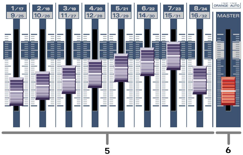
5. Track faders
Assignable
You can assign MIDI messages to each of these eight faders. Typically, you will use the track faders to control the track volume on your sequencer software.
6. Master fader (MASTER)
Assignable
You can assign a MIDI message to this fader. The master fader controls the master volume on your sequencer software. The final volume of the UR-80 itself is adjusted by its output volume knob.
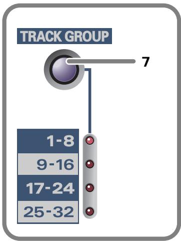
7. Track Group select button (TRACK GROUP)........
Assignable
You can assign four MIDI messages to the Track Group select button. Each time you press the button, one of the four messages will be transmitted.
The Track Group select button switches the group of tracks on your sequencer software whose parameters will be controlled by the track control knobs and track faders. This means that you can use the eight knobs and faders to control the parameters of 32 tracks.

Operating the Track Group select button does not switch the messages assigned to the Track Control knobs, Track Status button, and Track Faders. The Track Group select button transmits four different MIDI messages to your sequencer software to change the base track number on your software.
■ Master Control section
The Master Control section is where you can execute commands and control the transport on your sequencer software. Here you can also make settings for the UR-80's audio interface.
- The content that is controlled will depend on the software you are using.
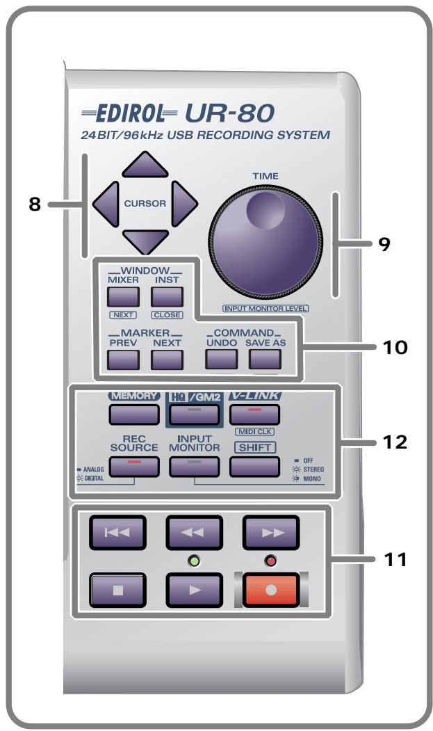
8.Cursor buttons Assignable
You can assign MIDI messages to these four buttons. Since you can also assign messages for when the SHIFT button is being held down, a total of eight MIDI messages can be assigned to these four buttons.
Use the cursor buttons to switch the track that is selected in your sequencer software or to move the focus point.
9 TIME dial.. Assignable
You can assign one MIDI message to this dial. Use the TIME dial to move the song location within your sequencer software.

If you hold down the SHIFT button and turn the TIME dial, the dial will adjust the input monitor level. For details on input monitoring, refer to p. 22.
10. Function buttons.. Assignable
You can assign MIDI messages to these six buttons. Since you can also assign messages for when the SHIFT button is being held down, a total of 12 MIDI messages can be assigned to these buttons. You will typically use the function buttons to execute various commands on your sequencer software.
11. Transport buttons Assignable
You can assign MIDI messages to these six buttons. Since you can also assign messages for when the SHIFT button is being held down, a total of 12 MIDI messages can be assigned to these buttons.
You can also assign MIDI messages to control the two LEDs located above the and transport buttons.
These buttons are typically used to control the transport of your sequencer software.
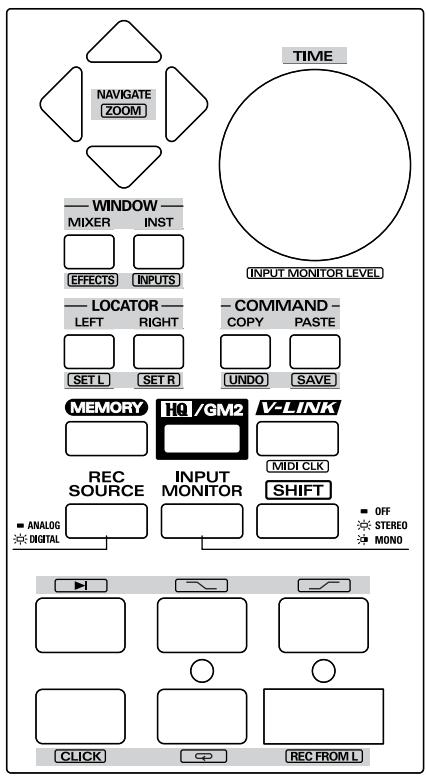
12. System Setting/Mode Select buttons
Use these buttons to switch settings and modes on the UR-80 itself.
You cannot assign MIDI messages to the System Setting/Mode Select buttons.
| Button name | Operation | |
| MEMORY | By holding down the MEMORY button and pressing a TRACK STATUS button you can switch among the eight memory sets stored within the UR-80.When you press this button, one of the TRACK STATUS button LEDs will light to indicate the currently selected memory set. | |
| HQ/GM2 | When the HQ/GM2 button is on, the Track Control section will be in Synth Edit mode, allowing you to control the parameters of the included software synthesizer. Press the button once again to turn it off and return to the previous track control functions.For details on Synth Edit mode refer to “Synth Edit mode (p. 68)”. | |
| V-LINK | When the V-LINK button is on, the Track Control section will be in V-LINK mode, allowing you to control V-LINK compatible video devices. Press the button once again to turn it off and return to the previous track control functions.For details on V-LINK mode refer to “V-LINK mode (p. 71)”. | |
| [MIDI CLK](SHIFT + V-LINK) | This switches MIDI Timing Clock (F8) transmission on/off.* When you press the SHIFT button, the LED will indicate the F8 on/off status—not the V-LINK on/off status. | |
| REC SOURCE | Switches the input signal that is being sent via USB to the computer as the recording source. | |
| ANALOG (LED unlit): | Only the signal from the input jacks will be sent to the computer. | |
| DIGITAL (LED lit): | Only the signal from the digital input jacks (coaxial or optical) will be sent to the computer. | |
| [INPUT MONITOR LEVEL](SHIFT + TIME) | Selects whether the input signal from the input jacks (1/2) and digital input jack will be sent to the headphone jack and master output jacks.Use [SHIFT] + TIME dial to adjust the monitor level.* Input monitoring can be switched on/off from ASIO 2.0 compliant software such as Cubase.* Adjusting the input monitor level will not change the recording level. | |
| OFF (LED unlit): | The input signal will not be output. Use this setting if you are “ thru-ing” the audio data within your computer, or if you have connected a mixer and are using the mixer to directly output the input signal for monitoring. | |
| STEREO (LED lit): | The input signal will be output in stereo. Use this setting if you have connected a stereo device to input jacks 1/2, or if you are using the digital input jack. | |
| MONO (LED blinking): | The input signal from the input jacks or digital input jack will be mixed to monaural and output. Use this setting if you have connected a monaural signal such as guitar or mic to the input jacks.* The audio signal sent via USB to your computer is stereo. | |
| SHIFT | Use this in conjunction with other buttons in the Master Control section. | |
- Buttons enclosed in square brackets [ ] (e.g., [MIDI CLK]) indicate that you are to operate the button while holding down the SHIFT button.
Audio Control section
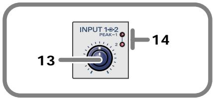
13. Input sensitivity knob
This dual concentric knob adjusts the input level to input jacks 1 and 2 (INPUT 1/L, INPUT 2/R).
The UR-80 provides XLR type and phone type input jacks, and you can use either type as appropriate for the equipment you want to connect. However, please be aware that the input sensitivity of these jacks will differ.
The inner knob adjusts the INPUT 1/L input level, and the outer (ring) knob adjusts the INPUT 2/R level.
Input levels
XLR type: -50- -10 dBu
Phone type: -35- +4 dBu
If you are connecting a low output level device such as a mic, we recommend that you use the XLR type input jack.
14. Peak indicators (PEAK)
These indicators show whether the sound being input to input jacks 1 and 2 (INPUT 1/L, INPUT-2/R) is distorting. Adjust the input sensitivity knob so that the peak indicators do not light. The peak indicators will light red at a level -6 dB below clipping.
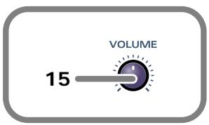
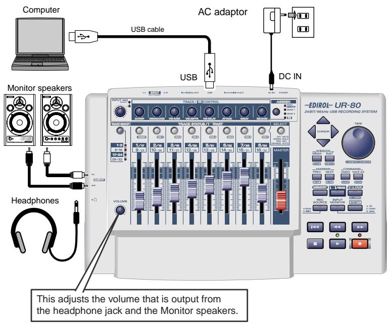
15. Output volume (VOLUME) knob
This adjusts the volume that is output from the headphone jack and the master output jacks.
- This does not affect the volume that is output from the digital output jacks.
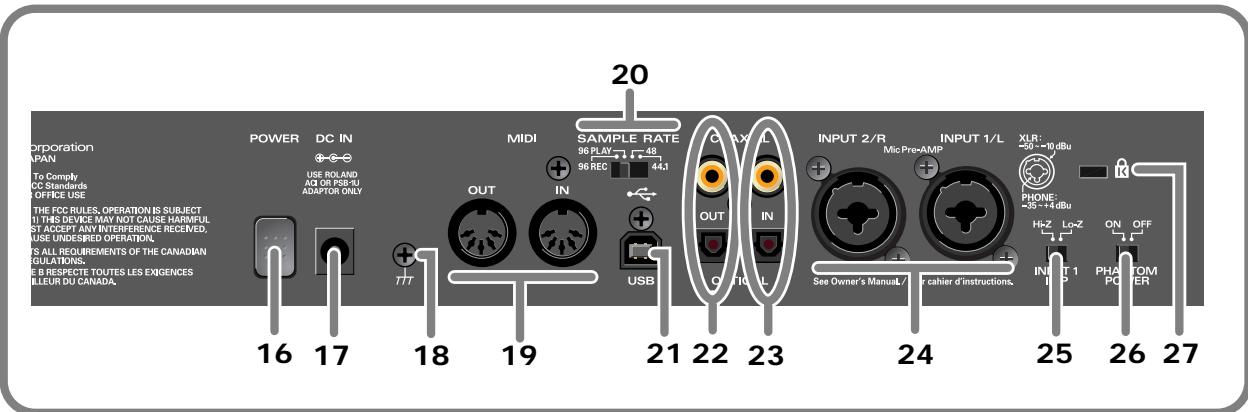
16. Power switch (POWER)
Press this switch to turn the power on/off. The power is on when the switch is pressed inward.
17. AC adaptor connector (DC IN)
Connect the included AC adaptor here
18. Grounding terminal
Depending on the circumstances of a particular setup, you may experience a discomforting sensation, or perceive that the surface feels jittery to the touch when you touch this device, microphones connected to it, or the metal portions of other objects, such as guitars. This is due to an infinitesimal electrical charge, which is absolutely harmless. However, if you are concerned about this, connect the ground terminal (see figure) with an external ground. When the unit is grounded, a slight hum may occur, depending on the particulars of your installation. If you are unsure of the connection method, contact the nearest Roland Service Center, or an authorized Roland distributor, as listed on the "Information" page.
Do not connect the grounding terminal to the following locations:
Water pipe (this can cause electric shock)
Gas pipe (this can cause explosion or fire)
- Telephone ground or lightning rod (hazardous during electrical storms)
19. MIDI IN/OUT connectors
Connect these connectors to the MIDI connectors of other MIDI devices to transmit and receive MIDI messages.
20. Sampling frequency select switch (SAMPLE RATE)
This switch selects the sampling frequency at which the audio signal will be recorded and played back.
- If you change the setting of this switch, you must then close all applications and turn the power of the UR-80 off, then on again.
- If you are using the 96 kHz sample rate, you cannot record and play back simultaneously. You must select either recording (96 REC) or playback (96 PLAY).
21. USB connector
Use a USB cable to connect this to your computer.
22. Digital output jacks
Use these jacks to output digital audio to a digital audio device such as a CD/MD/DAT.
23. Digital input jacks
Use these jacks to input digital audio from a digital audio device such as a CD/MD/DAT or from a MIDI sound module that has a digital output jack.
- If you have connected a digital device to the optical (OPTICAL) connector, the optical connector will take priority; the signals from the coaxial jacks will not be input.
You must use the appropriate type of cable for the digital output jack or digital input jack you are using.
COAXIAL. Coaxial cable
OPTICAL Optical cable
- The UR-80's digital input/output format complies with the S/P DIF standard.
24. Input jacks 1, 2 (INPUT 1/L, 2/R)
These are analog audio input jacks. You can connect either XLR type or phone type plugs. Balanced and unbalanced connections are supported for either type. 48V phantom power can be supplied to XLR type connections, allowing you to use phantom-powered condenser mics. In this case, turn the phantom power switch ON.
The XLR type and phone type jacks have different input sensitivity, as shown below.
XLR type.....-50--10 dBu
Phone type. -35- +4 dBu
If you are connecting a device with a low output level, such as a mic, we recommend that you use the XLR type input jack.

1:GND 2:HOT 3:COLD
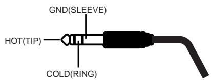
- The UR-80 provides balanced (XLR/TRS) type input jacks, which are wired as shown in the diagram. Please make sure that the device you are connecting is wired appropriately.
- The phantom power must be turned off unless you have connected a condenser mic that requires phantom power. Malfunctions can occur if you supply phantom power to a dynamic mic or audio playback device. For details on the specifications of your mic, refer to its owner's manual. (The UR-80's phantom power supply provides a maximum of 10mA at DC 48 V.)
- Do not connect different types of mic simultaneously; for example, do not connect a phantom-powered condenser mic to input jack 1 and a dynamic mic to input jack 2. Supplying phantom power to a dynamic mic or audio playback device will cause malfunctions.
25. Input impedance select switch (INPUT 1 IMP)
You can select either high impedance (Hi-Z) or low impedance (Lo-Z) for the device connected to input jack 1. If you connect a guitar to input jack 1, set this to high impedance (Hi-Z).
26. Phantom power switch (PHANTOM POWER)
This is an on/off switch for the phantom power that is supplied to the XLR type input jacks 1 and 2.
- The phantom power must be turned off unless you have connected a condenser mic that requires phantom power. Malfunctions can occur if you supply phantom power to a dynamic mic or audio playback device. For details on the specifications of your mic, refer to its owner's manual. (The UR-80's phantom power supply provides a maximum of 10mA at DC 48 V.)
27. Security slot (K)
- http://www.kensington.com/
Side panel
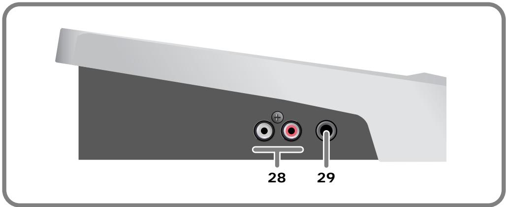
28. Master output jacks (RCA phono type)
These are analog audio output jacks. You can connect them to your external monitor speaker system.
29. Headphone jack
You can connect a set of headphones to this jack. The headphone jack will output the same signal as the master output jacks and digital output jacks. Sound will be output from the master output jacks even if headphones are connected.
- Use the output volume knob of the Audio Control section to adjust the volume of the headphone jack and master output jacks. It is not possible to adjust the volume that is output from the digital output jacks.
Basic operation
Basic connections and settings
This section explains basic connections and data routes for the UR-80.
- Before you make connections with other devices, you must turn down the volume of all devices to prevent malfunctions or speaker damage.
If you connect your headphones or monitor speakers as shown in the diagram, you will be able to monitor the playback from your software or the sound from instruments or audio devices connected to the UR-80.
Basic connections
Simply use a USB cable to connect the UR-80 to your computer.
Connecting the USB cable allows both MIDI data and audio data to be transferred.
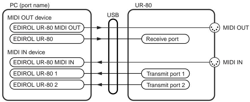
■MIDI flow
If the UR-80 and your computer are connected via USB cable
The MIDI data flow will be as shown below.
■ Audio flow (block diagram)

If you are using MIDI connections
Even if the UR-80 is not connected to your computer via a USB cable, you can connect the UR-80's MIDI IN/OUT connectors to a MIDI interface that is connected to your computer.
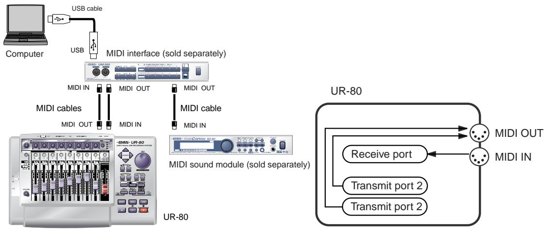
- When connected via MIDI, the audio functionality of the UR-80 will be unavailable.
Input/output devices
In order to obtain the best performance from your software, you must make the appropriate input/output device settings.
For details on these settings, refer to the owner's manual for your software.
- If you are unable to select the UR-80 in the device settings for your software, it is possible that the UR-80 driver was not installed correctly. Please reinstall the driver.
MIDI devices
| MIDI OUT device | |
| UR-80 MIDI OUT (Mac OS 9: UR-80 MIDI IN, OUT) | |
| If you specify UR-80 MIDI OUT as the output port for your sequencer software, messages will be transmitted from the MIDI OUT connector of the UR-80 itself. | |
| UR-80 (Mac OS 9/8: UR-80 1) | |
| Select this port if you want to send messages from your sequencer software to the UR-80 itself. | |
| MIDI IN device | |
| UR-80 MIDI IN (Mac OS 9: UR-80 MIDI IN, OUT) | |
| If you specify UR-80 MIDI IN as the input port for your sequencer software, messages will be input from the UR-80's MIDI IN connector. | |
| UR-80 1 UR-80 2 | |
| Select one of these ports if you want messages from the controllers to be received by your sequencer software. For each controller you can select the port that will be used. You may find it convenient (for example) to use UR-80 1 for messages to be recorded on a track or used to control a software synthesizer, and UR-80 2 for messages used to play back/stop your sequencer or perform mixing. Use UR-80 2 as the MIDI input device for UR-80 Editor. | |
Audio devices
| Audio output device | |
| EDIROL UR-80 | |
| This sends audio signals from your computer to the UR-80. If you are using Media Player you will normally choose this. You should also use this if you are using an application such as SO-NAR in WDM driver mode or a DirectX sound application. | |
| MME EDIROL UR-80 Out | |
| This sends audio signals from your computer to the UR-80. Use this if you are using an application that does not have a WDM driver mode, or if you want to use 24-bit audio with a non-ASIO application (such as Cool Edit).* Windows XP/2000 only | |
| Audio input devices | |
| EDIROL UR-80 | |
| This receives audio signals sent from the UR-80 to your computer. Normally, you should use this. You should also use this when using an application such as SONAR in WDM driver mode. | |
| MME EDIROL UR-80 In | |
| This receives audio signals sent from the UR-80 to your computer. Use this if you are using an application that does not have a WDM driver mode, or if you want to use 24-bit audio with a non-ASIO application (such as Cool Edit).* Windows XP/2000 only | |
| ASIO device | |
| Select “EDIROL UR-80” as the ASIO setting for your application if you are using the UR-80 with an ASIO application such as Cubase.* To prevent audio loops from causing oscillation or double monitoring, turn monitoring off in your application or use the ASIO Direct Monitor setting. | |
Some sequencer software that supports MIDI controllers lets you independently specify the MIDI input port used for recording MIDI tracks (the "MIDI IN port") and the MIDI input port used to control the software (the "CTRL IN port").

Sequencer software
UR-80
Normally, you will connect your MIDI keyboard to the MIDI IN port, and use it for recording your performance on tracks or using the MIDI Thru function of your software to play sound modules or soft synthesizers. The MIDI messages sent here have the meaning that is assigned to them by the MIDI specification. In other words, when you play the keyboard, note messages will be transmitted and recorded on the track, and the sound module that receives these messages will produce sound.
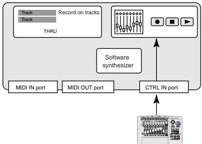
Sequencer software
UR-80
In contrast, the data received from the CTRL IN port is used to operate your software in the same way as data from your computer's mouse or keyboard; it will not be recorded on the tracks or "thru-ed" to your sound module or soft synthesizer. The MIDI messages sent here are interpreted in a completely different way than defined in the MIDI specification.
For this reason, messages that are input from the CTRL IN port are not normally "thru-ed" to your sound module or soft synthesizer.
For example, even if you play your keyboard to send a note-on message, the software that receives this message will not produce a note; instead, it might interpret this message as meaning that the PLAY/STOP button had been pressed.
- The actual operation that will occur will depend on the software you are using.
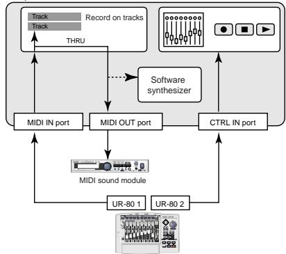
Sequencer software
Since the same MIDI message can be interpreted in completely different ways, as described above, the software lets you specify the MIDI IN port and CTRL IN port separately so that the two types can be distinguished. When the UR-80 is connected via USB, you can select either of the two MIDI ports (UR-80 1, UR-80 2) as the output destination for MIDI messages produced by the faders, knobs, and buttons of the UR-80.
In other words, by assigning "UR-80 1" as your software's MIDI IN port and "UR-80 2" as its CTRL IN port, you can do things like using the fader and button operations to
control mixer operations in your software while using the knobs to edit your software synthesizer. The output destination of the MIDI messages transmitted when you operate the UR-80's faders, knobs, and buttons can be specified separately for each controller. Use UR-80 Editor to assign the message and output destination for the controllers. For details, refer to "UR-80 Editor (p. 73)".
Controlling your software
You can assign the desired MIDI messages to the UR-80's knobs, faders, and buttons. A set of such MIDI message assignments is called a "memory set".
The UR-80 contains eight different memory sets in its internal memory. When shipped from the factory, the assignments of the PRESET memory set are selected.
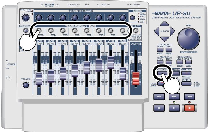
Switching memory sets
Hold down the MEMORY button and press a TRACK STATUS button to select a memory set.
Memory sets
| Memory | Contents |
| PRESET | This is the UR-80's basic memory set. It cannot be rewritten. Use this memory set if you will leave the messages of the UR-80 fixed and make assignments on your software. You will also use this memory set for SONAR. |
| USR 1 | Rewritable. With the factory settings, this is set for Cubase SX. |
| USR 2 | Rewritable. With the factory settings, this is set for Cubase VST. |
| USR 3 | Rewritable. With the factory settings, this is set to Logic. |
| USR 4 | Rewritable. With the factory settings, this is set for Pro Tools LE and Digital Performer 3. |
| USR 5 | Rewritable. With the factory settings, this is set for Reason. |
| USR 6 | Rewritable. With the factory settings, this is set for compatibility with MCR-8 Mode4 A/1-8. |
| USR 7 | Rewritable. With the factory settings, this is set for compatibility with MCR-8 Mode4 B/9-16. |
Memory set
Use PRESET.
Hold down the UR-80's MEMORY button and press Track Status button PRESET.
Software
You will need SONAR 2.0 or later, and the UR-80 Control Surface Plug-in.
The UR-80 Control Surface Plug-in is found in the SONAR Plugin folder of the included CD-ROM.
Double-click UR80CSP.EXE to start up the installer.
Follow the on-screen directions to install the software.
Settings in SONAR
- From the Options menu, choose Control Surfaces.
- In the Control Surfaces dialog box, click the button, and select "EDIROL UR-80" as the Control Surface.
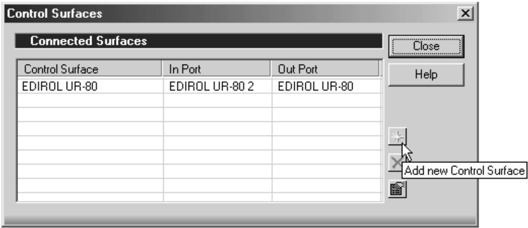
- Specify the in port and out port.
| Control Surface | In port | Out port |
| EDIROL UR-80 | EDIROL UR-80 2 | EDIROL UR-80 |

For details on using SONAR, refer to the SONAR owner's manual.
Functions assigned to the controllers
Track Control section
Track faders
Control the track volumes.
By using these faders in conjunction with the track group select button you can control 32 tracks.
Master fader
Control the volume of virtual main.
You can choose which virtual main you want to control in the Setting dialog of UR-80 Control
Surface Plag-in.
For details, refer to the online help for UR-80 Control Surface Plug-in.
Track Status buttons (TRACK STATUS/HQ PART)
Switch the status of the tracks.
By using these buttons in conjunction with the track group select button you can control 32 tracks.
| Mode | SELECT button status | Function |
| MUTE | OFF | Switches track mute on/off. On: lit Off: unlit |
| SOLO | GREEN | Switches track solo on/off. On: lit Off: unlit |
| REC | RED | Switches track record-ready on/off. On: lit Off: unlit |
| AUTO | ORANGE | Switches track automation recording on/off. On: lit Off: unlit |
Track Control knobs (TRACK/HQ CONTROL)
These knobs control track Pan, Send 1 level, and Send 2 level. Use the Assign button to select Pan, Send 1 level, or Send 2 level.
By using these knobs in conjunction with the track group select button you can control 32 tracks.
Track Group select button (TRACK GROUP)
This button switches the track group you are controlling.
| TRACK GROUP button status | Tracks controlled |
| 1-8 | Tracks 1-8 |
| 9-16 | Tracks 9-16 |
| 17-24 | Tracks 17-24 |
| 25-32 | Tracks 25-32 |
Master Control section
Cursor buttons
These buttons perform the following functions.
| Button | Function |
| Move up | |
| Move down | |
| Move left | |
| Move right | |
| [SHIFT]+ | Shrink display vertically |
| [SHIFT]+ | Expand display vertically |
| [SHIFT]+ | Shrink display horizontally |
| [SHIFT]+ | Expand display horizontally |
Function buttons
| Button | Function |
| MIXER | Open the Console window. |
| [NEXT] | Move to the next window. |
| INST | Open the Synth Rack window. |
| [CLOSE] | Close the window. |
| PREV | Move to the previous marker. |
| [SET] | Insert a marker. |
| NEXT | Move to the next marker. |
| [LIST] | Open the Marker window. |
| UNDO | Revert the most recent edit operation to its prior state. |
| [REDO] | Re-execute the most recent edit operation. |
| SAVE AS | Perform the Save As operation. |
| [SAVE] | Save. |
- Button names in square brackets [ ] indicate that you press the button while holding down the SHIFT button.
TIME dial
Turning the dial will move the cursor.
Transport buttons
These perform the following functions.
| Button | Function |
| ←→ | Move the cursor to the beginning of the song. |
| ↔ | Rewind. |
| → | Fast-forward. |
| ■ | Stop playback/recording. |
| ▶ | Start playback. |
| ◇ | Start recording. |
| [SHIFT]+ | Start recording automation. |
Memory set
Use USR1.
Hold down the UR-80's MEMORY button and press the track status button USR1.
Software
You will need Cubase SX and EDIROL UR-80 for SX.xml.
EDIROL UR-80 for SX.xml is located in the SX folder inside the Cubase Remote folder of the included CD-ROM.
Before you continue, copy EDIROL UR-80 for SX.xml onto your computer.
Settings in Cubase SX
- From the Devices menu, select Device Setup.
- Click the Add/Remove tab.
- In the Device Classes list, select Generic Remote and click [Add].
- In the device field, select Generic Remote, which you added in step 3, and click the Setup tab.
- Click [Import].
- Select EDIROL UR-80 for SX.xml (which you copied earlier), and click [Open].
- Specify the MIDI Input and MIDI Output.
| MIDI Input | MIDI Output |
| EDIROL UR-80 2 | EDIROL UR-80 |
- In the Devices field of the Device Setup dialog box, select All MIDI Inputs.
-
In the Device field of the Setup tab, click the EDIROL UR-80 2 Active field and set it to No.
-
Unless you make this setting, the MIDI messages transmitted from the UR-80 will be thru-ed to the MIDI tracks.
-
Click [OK] to close the dialog box.
Functions assigned to the controllers
Please affix the Cubase SX labels to the included template sheet. The explanation below will follow these settings.
CUBASE SX
Track Control section
Track faders
The faders control the volume of the mixer.
By using the faders in conjunction with the bank button, you can control 32 channels.
Master fader
Control the master gain of VST Mixer.
Track Status buttons (TRACK STATUS/HQ PART)
These buttons switch the status of each channel.
By using the buttons in conjunction with the bank button, you can control 32 channels.
| Mode | SELECT button status | Function |
| MUTE | OFF | Switches channel mute on/off. On: lit Off: unlit |
| SOLO | GREEN | Switches channel solo on/off. On: lit Off: unlit |
| READ | RED | Switches channel automation playback on/off. On: lit Off: unlit |
| WRITE | ORANGE | Switches channel automation recording on/off. On: lit Off: unlit |
Track Control knobs (TRACK/HQ CONTROL)
These knobs control channel Pan, Send 1 level, and Send 2 level. Use the Assign button to select Pan, Send 1 level, or Send 2 level.
By using these knobs in conjunction with the bank button you can control 32 channels.
Bank button (BANK)
This button switches the bank of channels you are controlling.
| BANK button status | Channels controlled |
| CH1-8 | Channels 1-8 |
| CH9-16 | Channels 9-16 |
| CH17-24 | Channels 17-24 |
| CH25-32 | Channels 25-32 |
Master Control section
Cursor buttons
These buttons perform the following functions.
| Button | Function |
| ▲ | Move up |
| ▼ | Move down |
| ▲ | Move left |
| ▲ | Move right |
| [SHIFT]+ | Shrink display vertically |
| [SHIFT]+ | Expand display vertically |
| [SHIFT]+ | Shrink display horizontally |
| [SHIFT]+ | Expand display horizontally |
Function buttons
| Button | Function |
| MIXER | Open/close the Mixer window. |
| [EFFECTS] | Open/close the VST Send Effect window. |
| INST | Open/close the VST Instruments window. |
| [INPUTS] | Open/close the VST Input window. |
| LEFT | Move the cursor to the left locator position. |
| [SET L] | Set the current cursor location as the left locator. |
| RIGHT | Move the cursor to the right locator position. |
| [SET R] | Set the current cursor location as the right locator. |
| COPY | Copy the currently selected object. |
| [UNDO] | Undo the preceding operation. |
| PASTE | Paste the copied object into the specified location. |
| [SAVE] | Save the current project to a file. |
Button names in square brackets [ ] indicate that you press the button while holding down the SHIFT button.
TIME dial
Turning the dial will move the cursor.
Transport buttons
These perform the following functions.
| Button | Function |
| ←→ | Move the cursor to the beginning of the song. |
| ←→ | Rewind the cursor. |
| → | Fast-forward the cursor. |
| ■ | Stop playback/recording. |
| → | Start playback. |
| ● | Start recording. |
| [SHIFT]+ | Move the cursor to the end of the song. |
| [SHIFT]+ | Switch auto punch-in on/off. |
| [SHIFT]+ | Switch auto punch-out on/off. |
| [SHIFT]+ | Switch the metronome on/off. |
| [SHIFT]+ | Switch cycle on/off. |
| [SHIFT]+ | Switch “Start Record at Left Locator” on/off. |
Memory set
Use USR2.
Hold down the UR-80's MEMORY button and press the track status button USR2.
Software
Cubase VST 5.1 or later is required. You will need Cubase VST and EDIROL UR-80 for VST.xml. EDIROL UR-80 for VST.xml is located in the VST folder inside the Cubase Remote folder of the included CD-ROM.
Before you continue, copy EDIROL UR-80 for VST.xml onto your computer.
Settings in Cubase VST (Windows users)
- From the Options menu, choose Remote Setup - Setup.
- Make the following settings in the VST Remote dialog box, and click [OK].
| Remote | Generic Remote |
| Input | EDIROL UR-80 2 |
| Output | EDIROL UR-80 |
- In the [Generic Remote] window that appears, click [EDIT] to open the Generic Remote Setup dialog box.
- Click [Import].
- Select EDIROL UR-80 for VST.xml (which you copied earlier), and click [Open].
- Click in the upper right to close the dialog box.
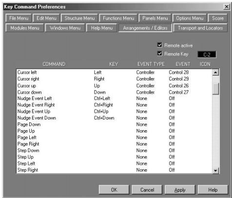
- Choose the Edit - Preferences - Key Commands.
- Click the Arrangements/Editors tab and make the following settings.
| Command | Event type | Event |
| Cursor left | Controller | Control 28 |
| Cursor right | Controller | Control 29 |
| Cursor up | Controller | Control 26 |
| Cursor down | Controller | Control 27 |
-
Check the Remote Active box.
-
Check the Remote Key box, and set it to C-2.
- Click [OK] to close the dialog box.
Settings in Cubase VST (Macintosh users)
- From the Options menu, choose Remote Setup | Setup.
- Make the following settings in the VST Remote dialog box, and click [OK].
| Remote | Generic Remote |
| Input | UR-80 2 |
| Output | UR-80 1 |
- In the Generic Remote window that appears, click [EDIT] to open the Generic Remote Setup dialog box.

- Click [Import].
- Select EDIROL UR-80 for VST.xml (which you copied earlier), and click [Open].
- Close the dialog box.
- From the Edit menu, choose Preferences | Key Commands.
- From the popup menu, choose Arrange/Editors and make the following settings.
| Command | Ev. type | Event |
| Cursor left | Controller | 28 |
| Cursor right | Controller | 29 |
| Cursor up | Controller | 26 |
| Cursor down | Controller | 27 |
- Check the Remote Active box.
- Check the Remote Key box, and set it to C-2.
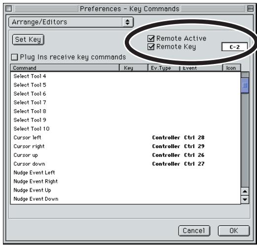
- Click [OK] to close the dialog box.
Functions assigned to the controllers
Please affix the Cubase VST labels to the included template sheet. The explanation below will follow these settings.
Track Control section
CUBASE VST
Track faders
The faders control the volume of the VST channel mixer.
By using the faders in conjunction with the bank button, you can control 16 audio channels,
8 VST-instrument channels, and 8 group channels.
Master fader
Control the master gain of VST Mixer.
Track Status buttons (TRACK STATUS/HQ PART)
These buttons switch the status of each channel.
By using the buttons in conjunction with the bank button, you can control 16 audio channels,
8 VST-instrument channels, and 8 group channels.
| Mode | SELECT button status | Function |
| MUTE | OFF | Switch channel mute on/off. On: lit Off: unlit |
| SOLO | GREEN | Switch channel solo on/off. On: lit Off: unlit |
| SELECT | RED | Select the channel. Selected: lit Not selected: unlit |
| - | ORANGE | Not used. |
Track Control knobs (TRACK/HQ CONTROL)
These knobs control channel Pan, Send 1 level, and Send 2 level. Use the Assign button to select Pan, Send 1 level, or Send 2 level.
By using these knobs in conjunction with the bank button you can control 16 audio channels,
8 VST-instrument channels, and 8 group channels.
Bank button (BANK)
This button switches the bank of channels you are controlling.
| BANK button status | Channels controlled |
| CH 1-8 | Audio channels 1-8 |
| CH 9-16 | Audio channels 9-16 |
| INST 1-8 | VST instrument channels 1-8 |
| GRP 1-8 | Group channels 1-8 |
Master Control section
Cursor buttons
These buttons perform the following functions.
| Button | Function |
| ▲ | Move up |
| ▼ | Move down |
| ← | Move left |
| → | Move right |
Function buttons
| Button | Function |
| MIXER | Open/close the VST Channel Mixer window. |
| [EFFECTS] | Open/close the VST Send Effect window. |
| INST | Open/close the VST Instruments window. |
| [INPUTS] | Open/close the VST Inputs window. |
| LEFT | Move the cursor to the left marker position. |
| [SET L] | Set the current cursor location as the left marker. |
| RIGHT | Move the cursor to the right marker position. |
| [SET R] | Set the current cursor location as the right marker. |
| COPY | Copy the currently selected object. |
| [UNDO] | Undo the preceding operation. |
| PASTE | Paste the copied object into the specified location. |
| [SAVE] | Save the current project to a file. |
*Button names in square brackets [ ] indicate that you press the button while holding down the SHIFT button.
TIME dial
Turning the dial will move the cursor.
Transport buttons
These perform the following functions.
| Button | Function |
| ←→ | Move the cursor to the beginning of the song. |
| ↔ | Rewind the cursor. |
| → | Fast-forward the cursor. |
| ■ | Stop playback/recording. |
| → | Start playback. |
| ● | Start recording. |
| [SHIFT]+ | Switch auto punch-in on/off. |
| [SHIFT]+ | Switch auto punch-out on/off. |
| [SHIFT]+ | Switch the metronome on/off. |
| [SHIFT]+ | Switch cycle on/off. |
Memory set
Use URS3.
Hold down the UR-80's MEMORY button and press the track status button USR3.
Software
Logic 5 version 5.5 or later is required.
- Each time you start up Logic, you must select the memory set for Logic on the UR-80 itself.
Settings in Logic
- Start up Logic.
- When Logic has started up, select the memory set for Logic on the UR-80.
-
Even if the memory set for Logic is already selected on the UR-80 itself, you must select the Logic memory set each time you start up Logic.
-
If the Setup window appears, click the Logic Control icon located in the right of the window.
-
If the Setup window does not appear, proceed to step 7.
-
In the Logic Control area in the left side of the Setup window, make the following Out Port settings. (Even if the display already indicates the settings shown below, make the settings again.)
Out Port: EDIROL UR-80 (for Windows or Mac OS X)
Out Port: UR-801 (for Mac OS 9)
- Close the Setup dialog box.
- Once again select the Logic memory set (USR3) on the UR-80.
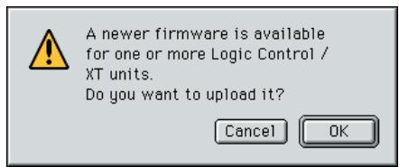
- If a dialog box like the following appears, click [Cancel].
Windows
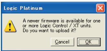
Macintosh
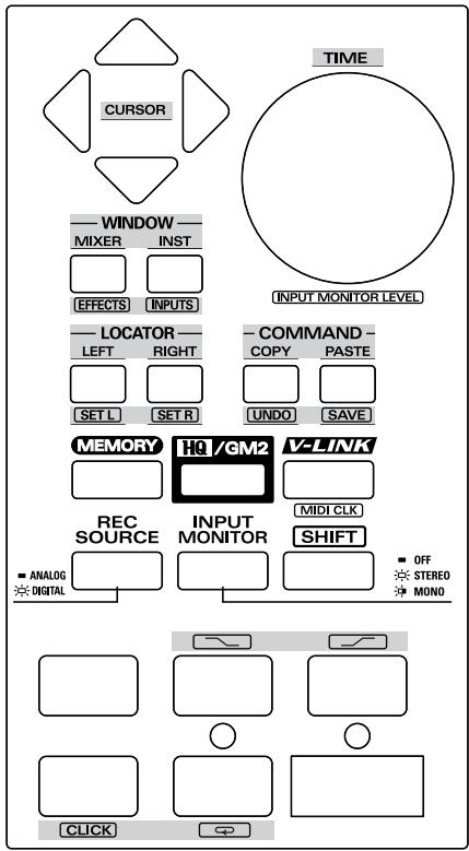
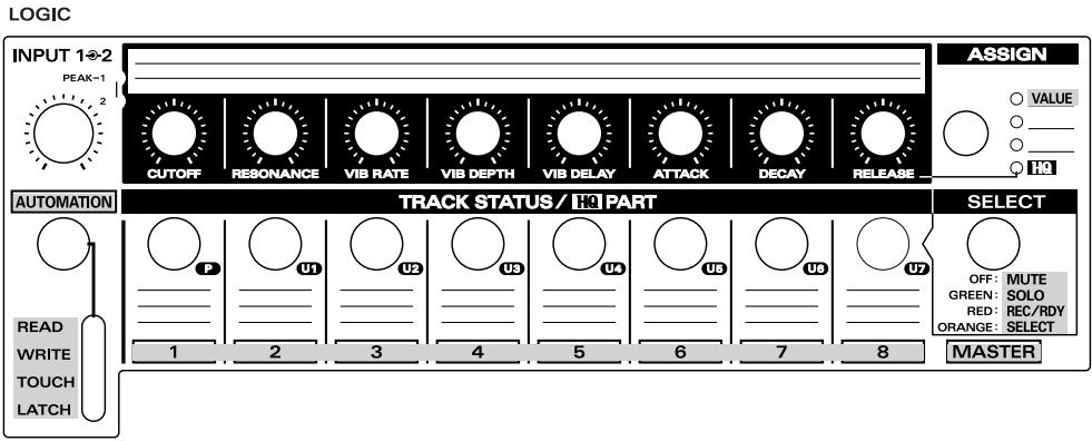
Functions assigned to the controllers
Please affix the Logic labels to the included template sheet. The explanation below will follow these settings.
Track Control section
Track faders
These adjust the level of each channel.
By switching the fader bank you can adjust the level of all channels.
- Use the FADER BANK function buttons to switch fader banks.
Master fader
Control the master volume of Audio Mixer.
Track Status buttons (TRACK STATUS/HQ PART)
These buttons switch the status of each channel.
By switching the fader bank you can control the status of all channels.
- Use the FADER BANK function buttons to switch fader banks.
| Mode | SELECT button status | Function |
| MUTE | OFF | Switch channel mute on/off. On: lit Off: unlit |
| SOLO | GREEN | Switch channel solo on/off. On: lit Off: unlit |
| REC/RDY | RED | Switch channel record-ready on/off. On: lit Off: unlit |
| SELECT | ORANGE | Select the channel to which an operation for an individual channel will apply. Selected: lit Not selected: unlit |
Track control knobs (TRACK/HQ CONTROL)
These knobs function as encoders.
The value will increase while the track control knob is turned toward the right, and will decrease while the knob is turned toward the left. The change (increase/decrease) will stop when you return the knob to the center position.
Use the ASSIGNMENT function button to switch the parameters that are controlled by these knobs.
Automation button (AUTOMATION)
This switches the automation mode of the currently selected channel.
| AUTOMATION button status | Operable channel/track |
| READ | Switch the automation mode to READ |
| WRITE | Switch the automation mode to WRITE |
| TOUCH | Switch the automation mode to TOUCH |
| LATCH | Switch the automation mode to LATCH |
Master Control section
Cursor buttons
These buttons perform the following functions.
| Button | Function |
| When the Track Mixer is displayed, these buttons select parameters or switch the send slot or equalizer band according to the function assigned to the track control knobs. | |
| Vertically shrink display | |
| [SHIFT]+ | Vertically expand display |
| [SHIFT]+ | Horizontally shrink display |
| [SHIFT]+ | Horizontally expand display |
Function buttons
| Button | Function | |
| FADER BANK | BANK < | Scroll the operated channel in steps of 8 channels. |
| BANK > | ||
| [CHANNEL <] | Scroll the operated channel in steps of 1 channel. | |
| [CHANNEL >] | ||
| ASSIGNMENT | Switch the parameters controlled by the Track Control knobs. | |
| PAN | Adjust the Pan/Angle of each channel. Use the left/right cursor buttons to switch the Pan/Angle parameter to be adjusted. | |
| SEND | Adjust the Send Level of each channel. Use the up/down cursor buttons to switch between send slots. Use the left/right cursor buttons to switch the Send Level parameter to be adjusted. | |
| [EQ] | Adjust the EQ Gain of each channel. Use the up/down cursor buttons to switch between equalizer bands. Use the left/right cursor buttons to switch the EQ Gain parameter to be adjusted. | |
| [TRACK] | Adjust the track parameters of each channel. Use the left/right cursor buttons to switch between parameters. | |
| WINDOW | ARRANGE | Switch the Arrangement window display on/off. |
| MIXER | Switch the Track Mixer window display on/off. | |
| [UNDO] | Undo the preceding edit operation. | |
| [SAVE] | Save the current song to a file. | |
- Button names in square brackets [ ] indicate that you press the button while holding down the SHIFT button.
JOG dial
Turning the dial will move the song position line (SPL). If Scrub mode is on, you can use the dial for scrub-playback.
Transport buttons
These perform the following functions.
| Button | Function |
| ←→ | Switch Scrub mode on/off. |
| ↔ | Rewind the song. Repeatedly pressing this button during rewind will speed up the rewind. Conversely, pressing ☑ during rewind will slow down and stop the re- wind. |
| >> | Fast-forwards the song. Repeatedly pressing this button during fast-forward will speed up the fast-forward. Conversely, pressing ☐ during fast-forward will slow down and stop the fast-forward. |
| ■ | Stop all transport functions. Press once again to return to the beginning of the song. |
| ▶ | Play from the current position in the song. |
| ● | Begin recording. |
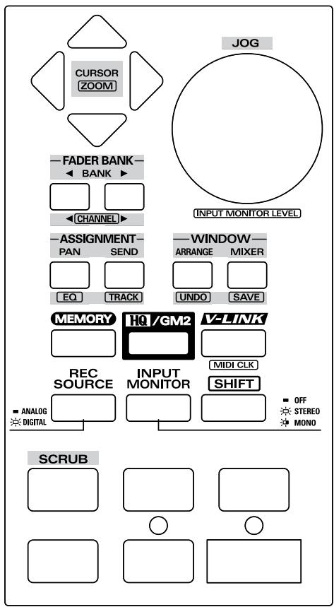
Pro Tools LE, Digital Performer 3
Memory set
Use USR4.
Hold down the UR-80's MEMORY button and press the Track Status button USR4.
Settings in ProTools LE
- From the Setups menu, choose Peripherals.
- Click MIDI Controllers.
- Set MIDI Controllers as follows.
Widows
| Type | Receive From | Send To |
| HUI | EDIROL UR-80 1 | EDIROL UR-80 |
Macintosh
| Type | Receive From | Send To |
| HUI | UR-80 1 | UR-80 1 |
Settings in Digital Performer
- From the Basics menu, choose Control Surface Setup.
- If the screen indicates "Press +' to add a Driver to your Configuration". Click the [+] key.
- In Driver ("Hardware" for 3.1 or earlier), select "HUI".
- In MIDI ("MIDI Communication" for 3.1 or earlier), select "UR-80 1".
Functions assigned to the controllers
Please affix the HUI labels to the included template sheet. The explanation below will follow these settings.
[DP]Indicates an operation for Digital Performer.
[PT] Indicates an operation for ProTools LE.
If neither of these symbols is shown, the operation applies to both systems.
Track Control section
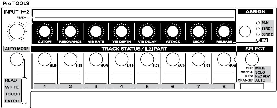
Track faders
The faders control the mixer volume.
You can control the eight tracks of the selected track bank. Use the cursor buttons to switch track banks.
Master fader
The master fader is not used.
Track Status buttons (TRACK STATUS/HQ PART)
These buttons switch the status of the track.
| Mode | SELECT button status | Function |
| MUTE | OFF | Switch track mute on/off. On: lit Off: unlit |
| SOLO | GREEN | Switch track solo on/off. On: lit Off: unlit |
| REC RDY | RED | Switch track record-ready on/off. On: lit Off: unlit |
| AUTO | ORANGE | Hold down this button and use the Automation Mode button (AUTO MODE) to change the automation setting of the track. |
Track Control knobs (TRACK/HQ CONTROL)
These knobs control track Pan, Send 1 level, and Send 2 level. Use the Assign button to select Pan, Send 1 level, or Send 2 level.
The value will increase while the knob is turned toward the right, and will decrease while the knob is turned toward the left. The change (increase/decrease) will stop when you return the knob to the center position (Shuttle mode).
Automation Mode button (AUTO MODE)
This selects the track automation setting.
In SELECT mode, hold down the Track Status button and press the Automation Mode button to change the automation setting of the corresponding track.
| AUTO MODE button status | Function |
| READ | Play back automation. |
| WRITE | Record automation. All automation will be overwritten. |
| TOUCH | Record automation in Touch Sense mode. Data will be overwritten only while you are operating the UR-80's faders. |
| LATCH | Record automation in Touch Sense mode. Data will be overwritten from the point you begin operating the UR-80's faders. |
Master Control section
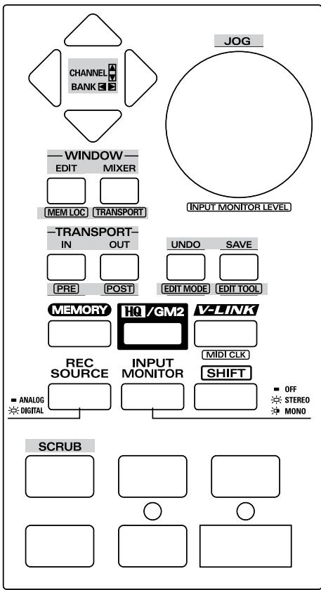
Cursor buttons
These buttons switch the track bank that is controlled by the UR-80's track controls.
| Button | Function |
| ▲ | Return the track bank by 1 track. |
| ▼ | Advance the track bank by 1 track. |
| ← | Move to the next track bank. |
| → | Move to the preceding track bank. |
Function buttons
| Button | Function |
| EDIT | [DP] Open the Editor window. |
| [PT] Open the Track window. | |
| [MEM LOCT] | [DP] Open the Marker window. |
| [PT] Open the Memory Location window. | |
| MIXER | Open the Mixer window. |
| [TRANS-PORT] | Open the Transport window. |
| IN | Set the current position as the Auto Record Start point (punch-in). |
| [PRE] | [DP] Set the current position as the Loop Play Start point. |
| [PT] Switch pre-roll on/off. | |
| OUT | Set the current position as the Auto Record End point (punch-in). |
| [POST] | [DP] Set the current position as the Loop Play End point. |
| [PT] Switch post-roll on/off. | |
| UNDO | Undo the previously executed operation. |
| [EDIT MODE] | [DP] Open the Nudge window. |
| [PT] Switch the edit mode. | |
| SAVE | Save the current project in a file. |
| [EDIT TOOL] | [DP] Open the Track window. |
| [PT] Switch the Edit tool. |
*Button names in square brackets [ ] indicate that you press the button while holding down the SHIFT button.
JOG dial
If the Scrub function is on, turning the dial will move the cursor.
Transport buttons
These buttons perform the following functions.
| Button | Function |
| ←→ | Turn the Scrub function on/off. |
| < | Rewind the cursor. |
| > | Fast-forward the cursor. |
| ■ | Stop playback/recording. |
| ▶ | Start playback. |
| ● | Start recording. |
Memory set
Use USR5.
Hold down the UR-80's MEMORY button and press the Track Status button USR5.
Software
Reason version 2.0 or later is required.
■ MIDI port settings
- From the Edit menu, choose Preferences.
- In Page, choose "Advanced MIDI".
- Make the following MIDI port settings.
| Any one of Bus A-D | EDIROL UR-80 1 |
| Remote Control | EDIROL UR-80 2 |
| MIDI Clock Sync | EDIROL UR-80 1 |

You can use UR-80 Editor to change the MIDI port used for MIDI Clock Sync. To do this, change the output port for the Sync Start and Sync Stop messages assigned to [SHIFT] ^+ STOP and [SHIFT] ^+ PLAY.
For details on how to make this change, refer to UR-80 Editor (p. 73).
Settings for reason transport and MIDI IN DEVICE
If you want to use the UR-80 to control Reason's modules or transport, you must make the following settings for each song.
- In the Options menu, choose Edit MIDI Remote Mapping to enable it.
- Click the Stop button of reason transport.
The MIDI Remote dialog box will appear.
- Check "Learn from MIDI Input".
- Press the UR-80's STOP button, and click [OK] in the MIDI Remote dialog box.
- Make the following assignments in the same way.
| UR-80 controller | reason transport | |
| Stop | ||
| Play | ||
| Rewind | ||
| Forward | ||
| Record | ||
| Loop ON/Off |
- In the Options menu, choose Edit MIDI Remote Mapping to disable it.
- In the Options menu, make sure that Enable MIDI Remote Mapping is checked. If it is not checked, select the menu item to enable it.
- Click the MIDI IN DEVICE module CHANNEL 16 button, and select the Mixer device that you want to control.
Controlling the tempo of the song
The UR-80 lets you use the time dial and cursor buttons to control the tempo of the song. If you want to control the song tempo from the UR-80, you will need to enable MIDI Clock Sync in Reason.
- You must first turn the UR-80's timing clock transmission on. To switch timing clock transmission on/off, press [SHIFT] + V-LINK.
Enabling MIDI Clock Sync
You can enable MIDI Clock Sync in either of the following two ways.
- In the Options menu, choose MIDI Clock Sync to add a check mark to it.
- Turn on the reason transport MIDI SYNC ENABLE button.


Operating reason transport
If MIDI Clock Sync is enabled, Play/Stop operations will be as follows.
- You cannot use Rewind or Forward while MIDI Clock Sync is enabled.
UR-80 controller
| UR-80 controller | reason transport |
| [SHIFT]+ | Stop |
| [SHIFT]+ | Play |
■ MIDI Remote Mapping settings
General-purpose MIDI control messages will be assigned to the UR-80's function buttons and TRACK GROUP button.
You can assign these controllers to the desired parameters of Reason.
- In the Options menu, choose Edit MIDI Remote Mapping to enable it.
- When you select a Reason module, a green arrow will be displayed for assignable controllers. Choose a controller.
- The MIDI Remote dialog box will appear; check "Learn from MIDI Input".
- Press the TRACK GROUP button or function button that you want to correspond with the selected controller.
- Click [OK] in the MIDI Remote dialog box.
- Repeat steps 2-5.
- When you have finished making settings, choose Edit MIDI Remote Mapping from the Options menu to disable it.
- In the Options menu, verify that Enable MIDI Remote Mapping is checked.
If it is not checked, select the menu item to enable it.
Functions assigned to the controllers
Please affix the Reason labels to the included template sheet. The explanation below will follow these settings.
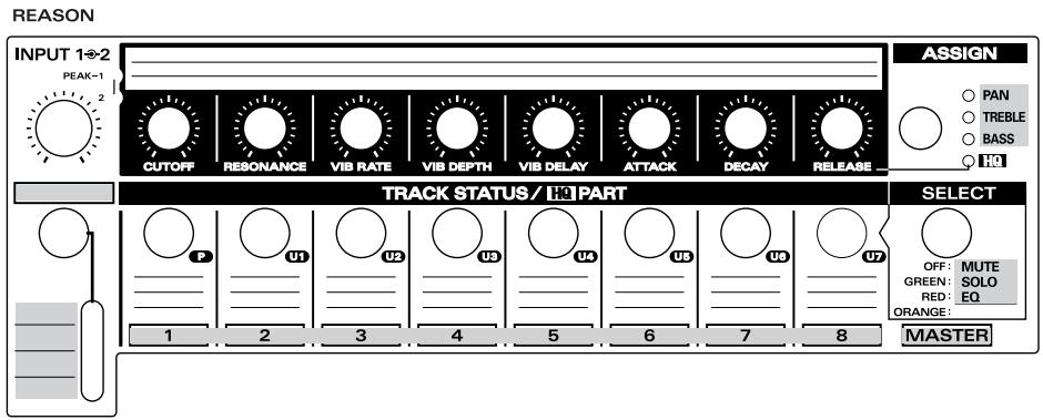
Track Control section
Track faders
The faders control the mixer volume.
You can control tracks 1-8.
- You cannot use the track group button to switch tracks.
Master fader
Control the master volume of Mixer.
Track Status buttons (TRACK STATUS/HQ PART)
These buttons switch the status of the tracks.
| Mode | SELECT button status | Function |
| MUTE | OFF | Switch track mute on/off. On: lit Off: unlit |
| SOLO | GREEN | Switch track solo on/off. On: lit Off: unlit |
| EQ | RED | Switch the equalizer (EQ) on/off. On: lit Off: unlit |
| — | ORANGE | You can assign any desired Reason parameters as general-purpose control buttons. |
Track Control knobs (TRACK/HQ CONTROL)
Use these knobs to control channel pan, equalizer treble (EQ TREBLE), and equalizer bass (EQ-BASS). Use the assign button to switch between pan, equalizer treble, and equalizer bass.
Master Control section
Cursor buttons
If you have enabled Reason's MIDI Clock Sync function and are controlling the tempo, these buttons set the tempo.
| Button | Tempo (BPM) |
| 80 | |
| 120 | |
| 145 | |
| 100 | |
| [SHIFT]+ | 20 |
| [SHIFT]+ | 180 |
| [SHIFT]+ | 250 |
| [SHIFT]+ | 60 |
TIME dial
If you have enabled Reason's MIDI Clock Sync function and are controlling the tempo, this dial continuously adjusts the tempo.
Transport buttons
These buttons perform the following functions.
| Button | Function |
| ←→ | Switch loop playback on/off. |
| ↔ | Rewind the cursor. |
| → | Fast-forward the cursor. |
| ■ | Stop playback/recording. |
| ▶ | Start playback. |
| ● | Start recording. |
| [SHIFT]+ | Stop playback during MIDI Clock Sync. |
| [SHIFT]+ | Start playback during MIDI Clock Sync. |
Roland MCR-8 compatible applications
You can use the UR-80 with software that is compatible with Roland MCR-8 mode 4.
- The MIDI channel of the transmitted messages is fixed at 16.
Memory set
Use USR6 or USR7. USR6 corresponds to MCR-8 mode 4-A. USR7 corresponds to mode 4-B.
Software settings
Select MCR-8 as the external controller for your software.
Specify UR-802 as the MIDI port used by your external controller. For details on settings, refer to the owner's manual for your software.
MCR-8 (mode 4-A) and UR-80 (USR6) controller assignments
| MCR-8 | UR-80 |
| C1 1-8 | TRACK CONTROL 1-8 [PAN] |
| S1 1-8 | TRACK STATUS 1-8 [MUTE] |
| S2 1-8 | TRACK STATUS 1-8 [SOLO] |
| C2 1-8 | TRACK FADER 1-8 |
| C1 MASTER | - |
| S1 MASTER | SHIFT + FUNCTION 5 [UNDO] |
| S2 MASTER | SHIFT + FUNCTION 6 [SAVE AS] |
| C2 MASTER | MASTER FADER |
| VALUE | TIME DIAL |
| S3 | SHIFT + |
| DEC | SHIFT + FUNCTION 3 [PREV] |
| INC | SHIFT + FUNCTION 4 [NEXT] |
| F1 | FUNCTION 1 [MIXER] |
| F2 | FUNCTION 2 [INST] |
| F3 | FUNCTION 3 [PREV] |
| F4 | FUNCTION 4 [NEXT] |
| F5 | FUNCTION 5 [UNDO] |
| F6 | FUNCTION 6 [SAVE AS] |
| F7 | SHIFT + FUNCTION 1 [MIXER] |
| F8 | SHIFT + FUNCTION 2 [INST] |
MCR-8 (mode 4-B) and UR-80 (USR7) controller assignments
| MCR-8 | UR-80 |
| C1 9-16 | TRACK CONTROL 1-8 [PAN] |
| S1 9-16 | TRACK STATUS 1-8 [MUTE] |
| S2 9-16 | TRACK STATUS 1-8 [SOLO] |
| C2 9-16 | TRACK FADER 1-8 |
| C1 MASTER | - |
| S1 MASTER | SHIFT + FUNCTION 5 [UNDO] |
| S2 MASTER | SHIFT + FUNCTION 6 [SAVE AS] |
| C2 MASTER | MASTER FADER |
| VALUE | TIME DIAL |
| S3 | SHIFT + |
| DEC | SHIFT + FUNCTION 3 [PREV] |
| INC | SHIFT + FUNCTION 4 [NEXT] |
| F1 | FUNCTION 1 [MIXER] |
| F2 | FUNCTION 2 [INST] |
| F3 | FUNCTION 3 [PREV] |
| F4 | FUNCTION 4 [NEXT] |
| F5 | FUNCTION 5 [UNDO] |
| F6 | FUNCTION 6 [SAVE AS] |
| F7 | SHIFT + FUNCTION 1 [MIXER] |
| F8 | SHIFT + FUNCTION 2 [INST] |
Recording audio
This chapter explains various ways in which you can connect and use the UR-80.
- To prevent malfunction and/or damage to speakers or other devices, always turn down the volume, and turn off the power on all devices before making any connections.
Basic use
You can connect headphones and/or monitor speakers as shown in the diagram, and monitor the playback of your application, or the sound of instruments or audio devices connected to the UR-80.
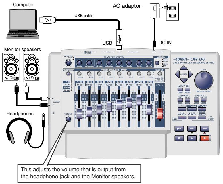
Using the sampling frequency
- You must set the UR-80's sampling frequency select switch to match the sampling frequency used by your application.
- If the sampling frequency select switch is set to 96 kHz REC, you will not hear the sound that is played back by your application.
- If the sampling frequency select switch is set to 96kHz PLAY, the sound of instruments or audio devices connected to the UR-80 cannot be recorded by your application.
- In order for the sampling frequency select switch setting to take effect, you switch off the UR-80, then turn it on again.
Recording guitar or bass
When you use your sequencer software to record your guitar playing while listening to the playback of audio data already on your computer, only the guitar performance will be newly recorded on the computer.
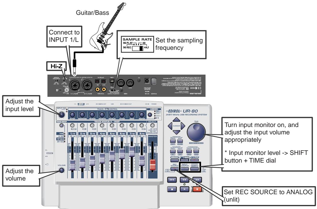
Connections
The sound of the instrument connected to input jack 1 will be recorded to channel L on your computer. The sound of the instrument connected to input jack 2 will be recorded to channel R.
Sampling frequency select switch
Set this to the same sampling frequency as selected in your recording software.
Input impedance select switch
Set this to Hi-Z.
Input sensitivity knob
Use the input sensitivity knob to adjust the input level. To obtain the best audio quality, adjust the input sensitivity knob until the level is as high as you can get it without causing the input peak indicator to light.
- Input monitor switch
Turn the input monitor switch on and adjust the input monitor level for the signal from your guitar or bass. This will not change the recording level.
To adjust the input monitor volume, hold down the SHIFT button and turn the TIME dial.
-REC SOURCE button
Set this to ANALOG (unlit).
Other notes
Don't connect anything to input jacks you are not using.
Recording from a mic
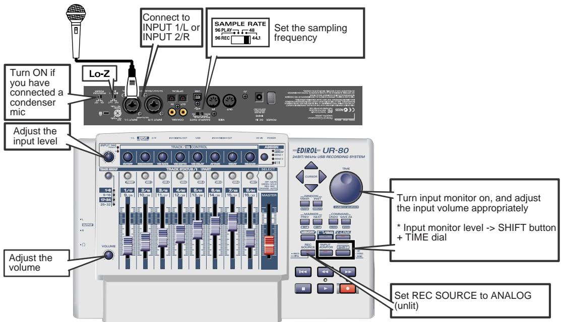
Connections
The sound from the mic connected to input jack 1 will be recorded on the left channel, and the sound of the mic connected to input jack 2 will be recorded on the right channel.
Sampling frequency select switch
Set this to the same sampling frequency as selected in your recording software.
Input impedance select switch
Set this to Lo-Z.
- Phantom power switch
If you are using a condenser mic, turn the phantom power switch on.
- If you connect a device that does not require phantom power, you must turn the phantom power switch off. Failure to do so will cause malfunctions.
Input sensitivity knob
Use the input sensitivity knob to adjust the input level. To obtain the best audio quality, adjust the input sensitivity knob until the level is as high as you can get it without causing the input peak indicator to light.
Input monitor switch
Turn the input monitor switch on and adjust the input monitor level for the signal from your mic. This will not change the recording level.
To adjust the input monitor volume, hold down the SHIFT button and turn the TIME dial.
-REC SOURCE button
Set this to ANALOG (unlit).
Other notes
Don't connect anything to input jacks you are not using. Howling could be produced depending on the location of microphones relative to speakers. This can be remedied by:
- Changing the orientation of the microphone(s).
- Relocating microphone(s) at a greater distance from speakers.
- Lowering volume levels.
Recording a keyboard
You can record your keyboard performance onto the computer as audio data.
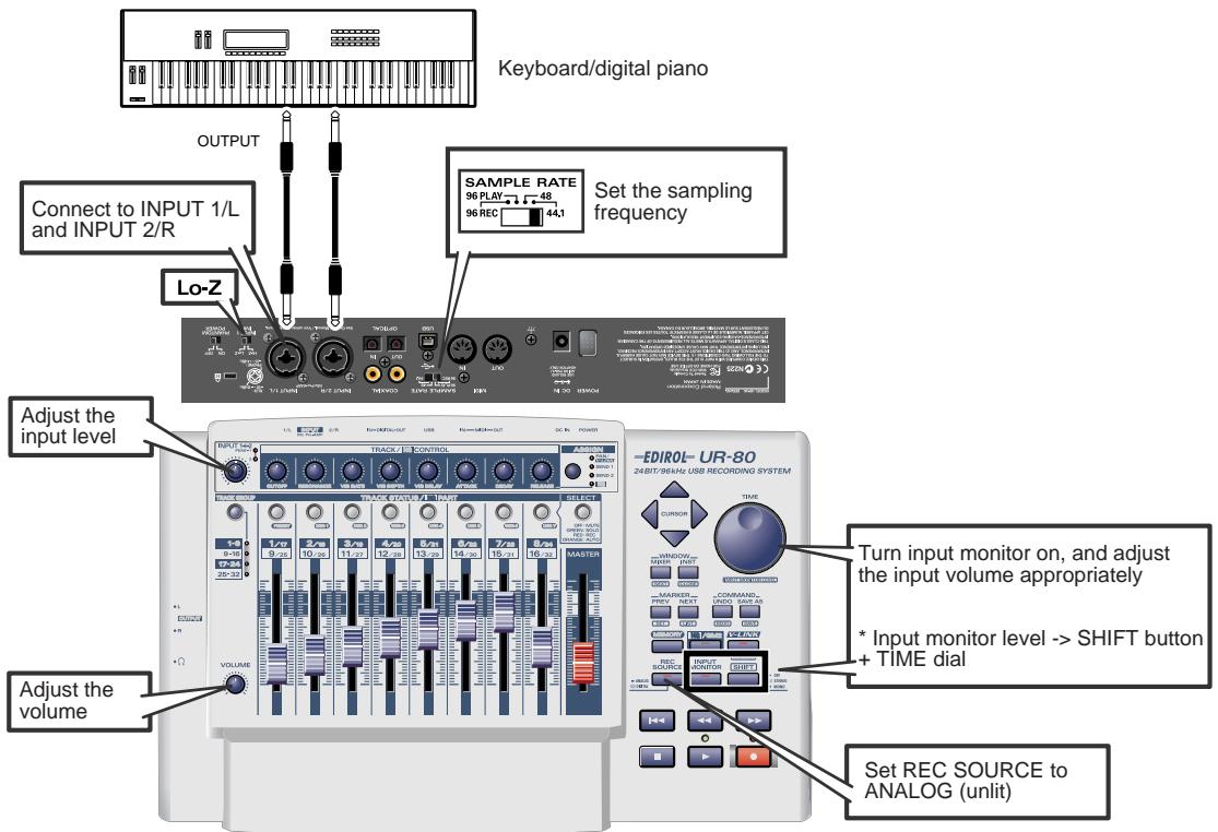
Connections
Use a phone jack cable to connect your keyboard (or other device) to input jacks 1 and 2.
Sampling frequency select switch
Set this to the same sampling frequency as selected in your recording software.
Input impedance select switch
Set this to Lo-Z.
Input sensitivity knob
Use the input sensitivity knob to adjust the input level. To obtain the best audio quality, adjust the input sensitivity knob until the level is as high as you can get it without causing the input peak indicator to light.
- Input monitor switch
Turn the input monitor switch on and adjust the input monitor level for the signal from your keyboard. This will not change the recording level.
To adjust the input monitor volume, hold down the SHIFT button and turn the TIME dial.
-REC SOURCE button
Set this to ANALOG (unlit).
Other notes
Don't connect anything to input jacks you are not using.
Recording from an audio device
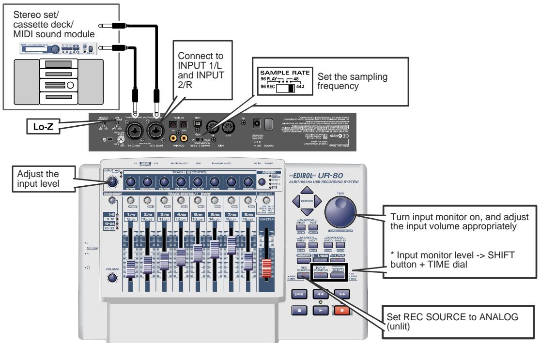
Connections
Use a phone jack cable to connect your audio device to input jacks 1 and 2.
Sampling frequency select switch
Set this to the same sampling frequency as selected in your recording software.
- Input impedance select switch
Set this to Lo-Z.
Input sensitivity knob
Use the input sensitivity knob to adjust the input level. To obtain the best audio quality, adjust the input sensitivity knob until the level is as high as you can get it without causing the input peak indicator to light.
Input monitor switch
Turn the input monitor switch on and adjust the input monitor level for the signal from your keyboard. This will not change the recording level.
-REC SOURCE button
Set this to ANALOG (unlit).
Other notes
Don't connect anything to input jacks you are not using.
Be aware of looped connections
If you connect the UR-80 to a device that "passes-through" the input audio to its output, the audio signal will loop between the UR-80 and the device, causing oscillation. This may produce an unexpectedly loud sound. Be careful to avoid this, since it may cause malfunctions or may damage your speakers.
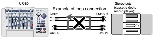
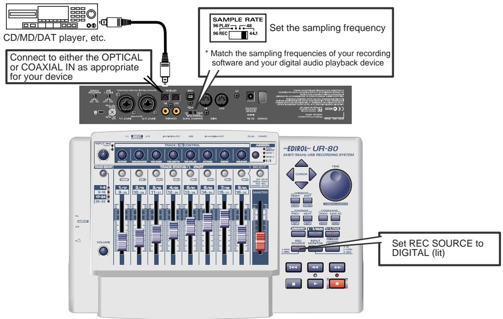
Connections
Use the appropriate type of cable to make connections to the digital input jack (OPTICAL/COAXIAL).
Sampling frequency select switch
Set this to the same sampling frequency as selected in your recording software.
-REC SOURCE button
Set this to DIGITAL (lit).
Other notes
Don't connect anything to input jacks you are not using.
- The UR-80 does not support professional digital audio formats.
Built-in sample rate converter
The sampling frequency of the signal being input from the digital input jack can be converted in real time by the UR-80.
48kHz 44.1kHz
32kHz 48kHz
The digital signal will be converted into the frequency specified by the sampling frequency select switch before it is recorded.
Recording the output of the UR-80 on a digital device
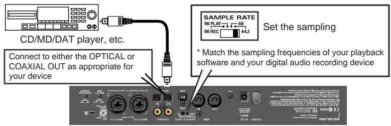
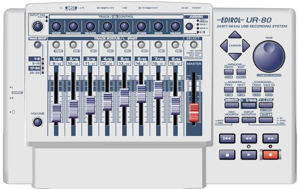
Connections
Use the appropriate type of cable to make connections to the digital output jack (OPTICAL/COAXIAL).
Sampling frequency select switch
Select the same sampling frequency for your audio data playback software, the UR-80, and your digital audio recording device (e.g., MD or DAT).
Other notes
Don't connect anything to input jacks you are not using.
- The UR-80 does not support professional digital audio formats.
- The UR-80 is not able to output the input signal from its input jacks directly to its digital output jacks. The digital output jacks always output only the audio signal that is being sent from your computer.
You can change the driver settings to adjust the latency of the audio. To adjust the latency, change the Buffer Size in the driver settings dialog box. Latency is the time delay from when an application plays back audio data until the sound is actually heard from an audio device such as the UR-80.
- As described in Opening the driver settings dialog box (p. 65), open the "Driver Settings" dialog box.
- Adjust the driver buffer size. The following setting will produce the shortest latency.
Windows:
Set "Audio Buffer Size" to the far left (Min).
Macintosh:
Set "Buffer Size" to the far left (Min).
- Click [OK] to close the driver settings dialog box.
- Restart the application that is using the UR-80. If you are using an application that has a function for testing audio devices, get it to perform its tests.
-
Play back audio data on your application. If interruptions occur in the sound, repeat this procedure, and gradually increase the buffer size specified in step 2 until interruptions no longer occur.
-
Depending on the application you are using, there may be a buffer size or latency adjustment function among the audio settings of the application as well. For details, refer to the operation manual for your application.
Using ASIO Direct Monitor
If you are using the UR-80 from an ASIO 2.0 compatible application, the UR-80's Input Monitor select switch can be controlled from your ASIO 2.0 compatible application.
- As described in Opening the driver settings dialog box, open the "Driver Settings" dialog box.
- Make the following settings. Check the "Use ASIO Direct Monitor" check box.
-
Click [OK] to close the driver settings dialog box.
-
Depending on your application, there may also be an ASIO Direct Monitor setting among the audio settings of your application. For details, refer to the operation manual for your application.
- When using ASIO Direct Monitor, monitoring may switch on/off at unexpected times, depending on the application settings and on the recording procedure. If this occurs, uncheck the check box in step 2 to disable ASIO Direct Monitor.
Opening the driver settings dialog box
If using Windows:
- Open the "Control Panel" and double-click "EDIROL UR-80".
-
The "EDIROL UR-80 Driver Settings" dialog box will appear.
-
In Windows XP, click "Switch to classic view" to switch the display to the classic view. EDIROL UR-80 will not be displayed unless the classic view is selected.
- In Windows Me, click "View all Control Panel options."
If using Macintosh:
Open the ASIO Control Panel from the Audio Settings dialog box of your ASIO-compatible application. The name of the Audio Settings dialog box and the procedure for opening the ASIO Control Panel will differ depending on your application. For details, refer to the operation manual for your application.
MEMO
Advanced operation
Synth Edit mode
When you turn on the HQ/GM2 button located in the Master Control area, the Track Control section will operate in Synth Edit mode. Synth Edit mode lets you edit the parameters of the included Hyper Canvas high-quality software synthesizer. Since the parameters are controlled by transmitting GM2-compatible MIDI messages, you can also use this mode to control any MIDI device that responds to GM2 MIDI messages.
When you want to return to controlling your sequencer software, press the HQ/GM2 button once again to turn it off.
- So that the master fader will always be able to control the overall volume, it will transmit the message assigned by the selected "Memory Set" (p. 349), regardless of the selected mode. Even in Synth Edit mode, the MASTER fader will not control the master volume of the software synthesizer.
In Synth Edit mode, the port from which MIDI messages are transmitted will be EDIROL UR-80 1 by default. You can use UR-80 Editor to change the output port.
- For details, refer to "UR-80 Editor" (p. 73).
Track faders
These adjust the volume of each channel.
You can control channels 1-16 by operating the track group select button.
■ Assign button (ASSIGN)
This button selects the parameters that will be controlled by the track control knobs. Press the assign button successively to cycle through the available choices: PAN SEND 1 SEND 2 HQ.
| Assign button | Parameter |
| PAN | Pan |
| SEND1 | Reverb send |
| SEND2 | Chorus send |
| HQ | Channel parameter |
■ Track control knobs (TRACK/HQ CONTROL)
These knobs control the pan, reverb send, chorus send, or channel parameters of each channel. Use the assign button to select the parameter.
When PAN, SEND1, or SEND2 is selected
The knobs will control the pan, reverb send, or chorus send of each channel. You can control channels 1-16 by operating the track group select button.
When HQ is selected
The knobs will control channel parameters. You can control the following eight parameters.
| Track control knob | Parameter |
| CUTOFF | Filter cutoff |
| RESONANCE | Filter resonance |
| VIB RATE | Vibrato rate |
| VIB深度 | Vibrato depth |
| VIB DELAY | Vibrato delay |
| ATTACK | Attack time |
| DECAY | Decay time |
| RELEASE | Release time |
Use the track status buttons and the track group select button to select the channel you want to control.
■ Track group select button (TRACK GROUP)
This button switches the group of channels (1-8/9-16) whose parameters will be controlled.
■ Track status buttons (TRACK STATUS/HQ PART)
When HQ is selected by the assign button, these buttons select the channel whose parameters will be controlled by the track control knobs. Use these buttons in conjunction with the track group select button.
Parameter list
- Output port: EDIROL UR-80 1 (default setting)
| Message (HEX) | Range (HEX) | Ch. | ||
| Track control knobs | CH 1/9 PAN | CC 10 (0A) | 0 (00) - 127 (7F) | 1/9 |
| CH 2/10 PAN | CC 10 (0A) | 0 (00) - 127 (7F) | 2/10 | |
| CH 3/11 PAN | CC 10 (0A) | 0 (00) - 127 (7F) | 3/11 | |
| CH 4/12 PAN | CC 10 (0A) | 0 (00) - 127 (7F) | 4/12 | |
| CH 5/13 PAN | CC 10 (0A) | 0 (00) - 127 (7F) | 5/13 | |
| CH 6/14 PAN | CC 10 (0A) | 0 (00) - 127 (7F) | 6/14 | |
| CH 7/15 PAN | CC 10 (0A) | 0 (00) - 127 (7F) | 7/15 | |
| CH 8/16 PAN | CC 10 (0A) | 0 (00) - 127 (7F) | 8/16 | |
| CH 1/9 REVERB SEND | CC 91 (5B) | 0 (00) - 127 (7F) | 1/9 | |
| CH 2/10 REVERB SEND | CC 91 (5B) | 0 (00) - 127 (7F) | 2/10 | |
| CH 3/11 REVERB SEND | CC 91 (5B) | 0 (00) - 127 (7F) | 3/11 | |
| CH 4/12 REVERB SEND | CC 91 (5B) | 0 (00) - 127 (7F) | 4/12 | |
| CH 5/13 REVERB SEND | CC 91 (5B) | 0 (00) - 127 (7F) | 5/13 | |
| CH 6/14 REVERB SEND | CC 91 (5B) | 0 (00) - 127 (7F) | 6/14 | |
| CH 7/15 REVERB SEND | CC 91 (5B) | 0 (00) - 127 (7F) | 7/15 | |
| CH 8/16 REVERB SEND | CC 91 (5B) | 0 (00) - 127 (7F) | 8/16 | |
| CH 1/9 CHORUS SEND | CC 93 (5D) | 0 (00) - 127 (7F) | 1/9 | |
| CH 2/10 CHORUS SEND | CC 93 (5D) | 0 (00) - 127 (7F) | 2/10 | |
| CH 3/11 CHORUS SEND | CC 93 (5D) | 0 (00) - 127 (7F) | 3/11 | |
| CH 4/12 CHORUS SEND | CC 93 (5D) | 0 (00) - 127 (7F) | 4/12 | |
| CH 5/13 CHORUS SEND | CC 93 (5D) | 0 (00) - 127 (7F) | 5/13 | |
| CH 6/14 CHORUS SEND | CC 93 (5D) | 0 (00) - 127 (7F) | 6/14 | |
| CH 7/15 CHORUS SEND | CC 93 (5D) | 0 (00) - 127 (7F) | 7/15 | |
| CH 8/16 CHORUS SEND | CC 93 (5D) | 0 (00) - 127 (7F) | 8/16 | |
| CUTOFF | CC 74 (4A) | 0 (00) - 127 (7F) | select (*1) | |
| RESONANCE | CC 71 (47) | 0 (00) - 127 (7F) | select (*1) | |
| VIB RATE | CC 76 (4C) | 0 (00) - 127 (7F) | select (*1) | |
| VIB DEPTH | CC 77 (4D) | 0 (00) - 127 (7F) | select (*1) | |
| VIB DELAY | CC 78 (4E) | 0 (00) - 127 (7F) | select (*1) | |
| ATTACK | CC 73 (49) | 0 (00) - 127 (7F) | select (*1) | |
| DECAY | CC 75 (4B) | 0 (00) - 127 (7F) | select (*1) | |
| RELEASE | CC 72 (48) | 0 (00) - 127 (7F) | select (*1) | |
| Track faders | CH 1/9 VOLUME | CC 7 (07) | 0 (00) - 127 (7F) | 1/9 |
| CH 2/10 VOLUME | CC 7 (07) | 0 (00) - 127 (7F) | 2/10 | |
| CH 3/11 VOLUME | CC 7 (07) | 0 (00) - 127 (7F) | 3/11 | |
| CH 4/12 VOLUME | CC 7 (07) | 0 (00) - 127 (7F) | 4/12 | |
| CH 5/13 VOLUME | CC 7 (07) | 0 (00) - 127 (7F) | 5/13 | |
| CH 6/14 VOLUME | CC 7 (07) | 0 (00) - 127 (7F) | 6/14 | |
| CH 7/15 VOLUME | CC 7 (07) | 0 (00) - 127 (7F) | 7/15 | |
| CH 8/16 VOLUME | CC 7 (07) | 0 (00) - 127 (7F) | 8/16 | |
- 1: The transmit channel will be the same MIDI channel as the channel (HQ PART) selected by the track status buttons.
What is V-LINK mode?
This mode lets you control V-LINK compatible video devices.
V-LINK ( V-LINK ) is a function that lets you perform music integrated with video. By using V-LINK-compatible video devices, visual effects can be easily linked to, and made part of the expressive elements of a performance.
When you turn on the V-LINK button located in the Master Control section, the Track Control section will be in "V-LINK mode." When the UR-80 enters V-LINK mode, it will transmit a V-LINK ON message, Sender Model Name message, and V-LINK Initialization message. When you press the V-LINK button once again, the UR-80 will transmit a V-LINK OFF message and will then exit V-LINK mode. The V-LINK initialization message is a MIDI message of up to 255 bytes. With the factory settings, the contents of the "Parameter list" (below) will be transmitted as the V-LINK initialization message. You can use the UR-80 Editor to change this message. For details on the settings, refer to the on-line help for UR-80 Editor.
Parameter list
In V-LINK mode, the following messages are assigned. You can set the output port in UR-80 Editor.
- Output port: EDIROL UR-80 1 (default setting)
| Message | Range (HEX) | Ch. | Default assignment | ||
| Track control knobs | 1 | CC 16 (10) | 0 (00)-127 (7F) | 16 | Playback Speed Ctrl |
| 2 | CC 17 (11) | 0 (00)-127 (7F) | 16 | Color Cr Ctrl | |
| 3 | CC 18 (12) | 0 (00)-127 (7F) | 16 | Color Cb Ctrl | |
| 4 | CC 19 (13) | 0 (00)-127 (7F) | 16 | Brightness Ctrl | |
| 5 | CC 20 (14) | 0 (00)-127 (7F) | 16 | Output Fade | |
| 6 | CC 21 (15) | 0 (00)-127 (7F) | 16 | (no assignment) | |
| 7 | CC 22 (16) | 0 (00)-127 (7F) | 16 | (no assignment) | |
| 8 | CC 23 (17) | 0 (00)-127 (7F) | 16 | (no assignment) | |
| Track faders | 1 | CC 24 (18) | 0 (00)-127 (7F) | 16 | Dissolve Time Ctrl |
| 2 | CC 25 (19) | 0 (00)-127 (7F) | 16 | Audio Level Ctrl | |
| 3 | CC 26 (1A) | 0 (00)-127 (7F) | 16 | VFX 1 Ctrl | |
| 4 | CC 27 (1B) | 0 (00)-127 (7F) | 16 | VFX 2 Ctrl | |
| 5 | CC 28 (1C) | 0 (00)-127 (7F) | 16 | VFX 3 Ctrl | |
| 6 | CC 29 (1D) | 0 (00)-127 (7F) | 16 | VFX 4 Ctrl | |
| 7 | CC 30 (1E) | 0 (00)-127 (7F) | 16 | (no assignment) | |
| 8 | CC 31 (1F) | 0 (00)-127 (7F) | 16 | (no assignment) | |
| Track status buttons | 1/9/17/25 | Program Change | 1/9/17/25 | 16 | Play video clip 1/9/17/25 |
| 2/10/18/26 | Program Change | 2/10/18/26 | 16 | Play video clip 2/10/18/26 | |
| 3/11/19/27 | Program Change | 3/11/19/27 | 16 | Play video clip 3/11/19/27 | |
| 4/12/20/28 | Program Change | 4/12/20/28 | 16 | Play video clip 4/12/20/28 | |
| 5/13/21/29 | Program Change | 5/13/21/29 | 16 | Play video clip 5/13/21/29 | |
| 6/14/22/30 | Program Change | 6/14/22/30 | 16 | Play video clip 6/14/22/30 | |
| 7/15/23/31 | Program Change | 7/15/23/31 | 16 | Play video clip 7/15/23/31 | |
| 8/16/24/32 | Program Change | 8/16/24/32 | 16 | Play video clip 8/16/24/32 | |
| Track group select button | 1-8 | BF 00 00 BF 20 00 | - | - | Video palette1 |
| 9-16 | BF 00 01 BF 20 00 | - | - | Video palette2 | |
| 17-24 | BF 00 02 BF 20 00 | - | - | Video palette3 | |
| 25-32 | BF 00 03 BF 20 00 | - | - | Video palette4 |
In V-LINK mode, you cannot control the track parameters of your sequencer software (or the like) from the Track Control section. If you want to resume controlling your sequencer software, press the V-LINK button to turn it off.
Controllers used in V-LINK mode
Please affix the V-LINK labels to the included template sheet.
fig.VLinkTrackControl
V-LINK
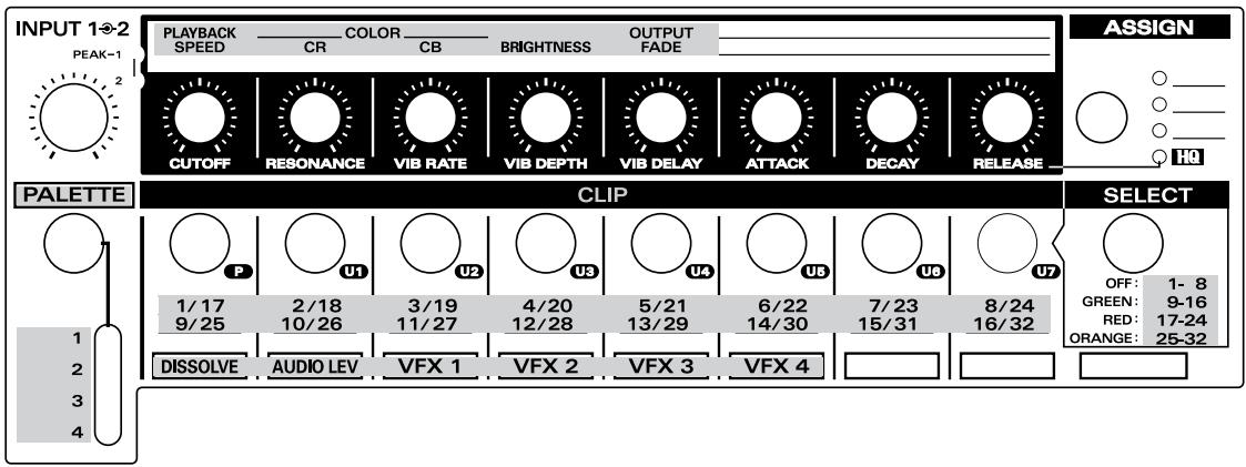
UR-80 Editor lets you use your computer to create memory sets for the UR-80. The UR-80 has a total of 43 controllers. By using these in conjunction with the SHIFT button and the LED indicators, you can assign 136 different MIDI messages to these controllers. Such a collection of 136 MIDI messages is called a "memory set." The UR-80 itself can store seven memory sets and one preset memory. () "Memory sets (p. 349)"
UR-80 Editor lets you transfer memory sets to and from the UR-80, edit the settings, and save/load memory sets in SMF format. It also lets you make system settings for the UR-80 itself.
You can view the online help from the Help menu of UR-80 Editor. The following pages provide a basic explanation of what UR-80 Editor can do. For details, refer to the on-line help for UR-80 Editor.
Starting up UR-80 Editor
Before you start up UR-80 Editor, use a USB cable to connect the UR-80 to your computer, and turn on the power.
Windows users
From the Start menu, select Programs (in Windows XP, "All Programs"), and from the menu that appears, choose UR-80 Editor UR-80 Editor.
Macintosh users
Double-click the UR-80 Editor icon located in the folder in which the software was installed.
MIDI Port settings
In order to transfer memory sets between the UR-80 and UR-80 Editor, or to make system settings, you must specify the MIDI port that UR-80 Editor is to use.
Here's how to make settings when you have connected the UR-80 to your computer via USB. If you are using the MIDI connectors to make connections, specify the input/output ports of the connected MIDI device.
Windows users
- From the Options menu, choose MIDI Devices.
- In the MIDI Devices dialog box that appears, make the following settings.
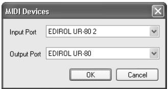
| Input port | EDIROL UR-80 2 |
| Output port | EDIROL UR-80 |
- Click [OK] to close the dialog box.
Macintosh users
Before you continue, make OMS or FreeMIDI settings as appropriate for your MIDI system. For details on making these settings, refer to Readme-E.HTM located in the driver folder of the included CD-ROM.
- From the Options menu, choose MIDI Devices.
- In the MIDI Devices dialog box that appears, make the following settings.
Mac OS 9
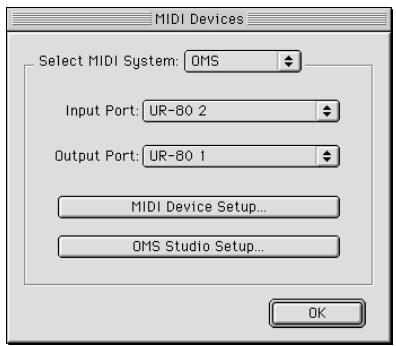
| MIDI System: | Make the appropriate selection for your system |
| Input port: | UR-80 2 |
| Output port: | UR-80 1 |
Mac OS X
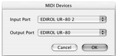
| Input port: | UR-80 2 |
| Output port: | UR-80 |
- Click [OK] to close the dialog box.
UR-80 Editor window
Main window
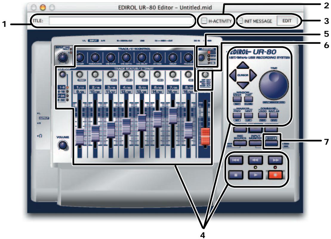
1. TITLE
Here you can input a name for the memory set you created.

You must input single-byte (English) characters. Double-byte (Japanese) character input is not supported.
The name you input here will also be reflected in the HTML file that is output when you Export assign list from the File menu.
2. H-ACTIVITY check box
The UR-80's H-ACTIVITY will turn ON when a memory set whose H-ACTIVITY check box is loaded into the UR-80.
Turn this on when using specific software (such as Pro Tools LE). If H-ACTIVITY is on, a message of "90 00 7F" will be transmitted from the "UR-80 1" port at intervals of approximately 500 ms.
3. INITMESSAGE assignment area
Here you can freely specify the MIDI message that will be transmitted when this memory set is selected. For details, refer to “Memory Set Initial Message (p. 80)”.
4. Controllers
Click the controller to which you want to assign a MIDI message. When you click a controller, the Message Assign window (p. 78) will open.
5.Assign button
This switches the MIDI messages assigned to the track control knobs in the order of PAN SEND 1 SEND 2.
Operating the Assign button will also change the "Assigned MIDI messages" display that appears when you select the Options menu command Show Messages.
6. Select button
This switches the assignment of the Track Status buttons in the order of
MUTE SOLO REC AUTO.
Operating the Assign button will also change the "Assigned MIDI messages" display that appears when you select the Options menu command Show Messages.
7. SHIFT button
You can assign MIDI messages to controllers operated in conjunction with the SHIFT button. In this case, the window will show only those controllers that can be operated in conjunction with the SHIFT button.
- Of controllers 4.-7., the mouse cursor will change shape for those that can be clicked.
■ MIDI messages that you can assign to controllers
| Message | Explanation | Assignable parameters |
| NO ASSIGN | Defeats the assignment. Operating this controller will not transmit any message. | |
| Channel Message Note | Assigns a Note message. | MIDI Channel, Note Number, Velocity |
| Ch. Pressure | Assigns a Channel Pressure message. | MIDI Channel, Mix Value, Max Value |
| Poly.Key Pressure | Assigns a Polyphonic Key Pressure message. | MIDI Channel, Note Number, Min Value, Max Value |
| Control Change | Assigns a Control Change message. | MIDI Channel, Control Number, Min Value, Max Value |
| Pitch Bend Change | Assigns a Pitch Bend message. | MIDI Channel, Min Value, Max Value |
| Program Change | Assigns a Program Change message.* The value of the program number has a range of 1-128. | MIDI Channel, Mix Value, Max Value |
| Bank/Program Change | Assigns a Bank Select message and Program Change message.* The value of the Bank Select message is fixed.* The value of the program number has a range of 1-128. | MIDI Channel, Bank MSB, Bank LSB, Min Value, Max Value, |
| RPN | Assigns a Registered Parameter Number.* The data entry LSB range is fixed at 0-127. | MIDI Channel, RPN MSB, RPN LSB, MSB Min Value, MSB Max Value, Send LSB |
| NRPN | Assigns a Non-Registered Parameter Number.* The data entry LSB range is fixed at 0-127. | MIDI Channel, NRPN MSB, NRPN LSB, MSB Min Value, MSB Max Value, Send LSB |
| System Common/Realtime | Assigns a System Common or System Realtime message. | Use the Status: field to select the desired message. |
| Free Message | Assign any desired MIDI message of up to 24 bytes. (You can assign more than one message.) | MIDI message of up to 24 bytes, Data Type, Min Value, Max Value |
| Tempo | Assigns Tempo Control for transmitting MIDI Timing Clock messages.* Use UR-80 Editor to specify the output destination of the timing clock messages. For details, refer to “System set-tings (p. 82)”. | Min Tempo, Max Tempo |
■Assigning a MIDI message
Message Assign window
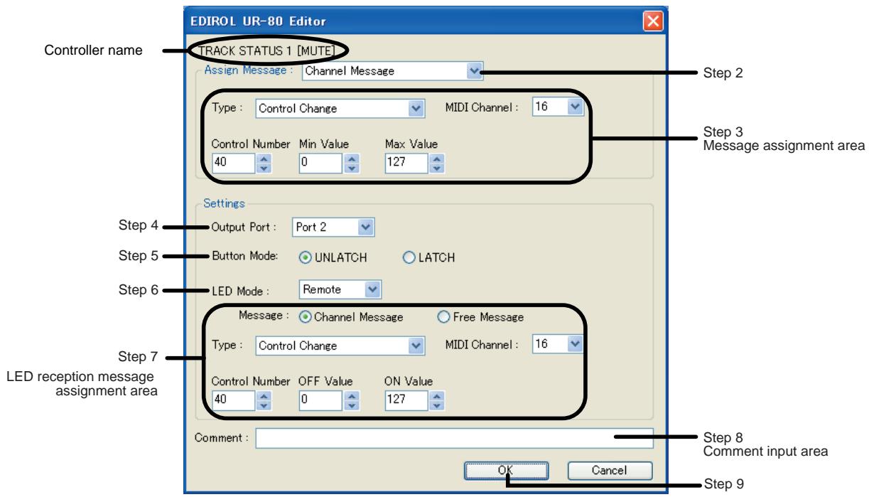
- In the Main window, click the controller to which you want to assign a message.
- In the Assign Message area of the Message Assign window, select the type of message that you want to assign.
- According to the type of message you selected, use the fields of the Assign Message area to specify each parameter of the message. Most parameter fields are specified as a decimal number. However, for a Free Message, you should input hexadecimal values in the Message input area.
- Specify the output port in Output Port.
- If the controller is a button, specify the Button Mode. If the controller is a knob, specify the Knob Mode.
- If the controller is a button with LED, specify the LED Mode.
-
If you specified the LED Mode as “Remote”, specify the LED reception message. The LED reception message field lets you select either Channel Message or Free Message. The parameters are the same as for a conventional assignment, with the following exceptions.
-
Min Value will be the OFF value for the LED reception message. The LED will turn off when this value is received.
- Max Value will be the ON value for the LED reception message. The LED will turn on when this value is received.
-
There will be no Send LSB check box for RPN or NRPN.
-
If desired, input a comment in the Comment field.
- Click [OK].
■ Checking the assigned MIDI messages
You can check the assigned MIDI messages in either of the following ways.
[Method 1]
From the File menu, choose View assign list.
All parameters of the MIDI messages assigned to the controllers will be displayed in HTML format. This method is convenient when you need to see detailed data, or for final checking.
When you choose the File menu command Export assign list, the same parameter list will be output as an HTML file.
[Method 2]
- From the Options menu, choose Show Messages.
A summary of the MIDI messages assigned to each controller will be displayed in the main window as follows. This method is convenient when you are making assignments, or when you want to check the overall assignments.
![ROLAND UR-80 - [Method 2] - 1](/content/2020/04/130972/images/01e6906e8e0a2d2b9ffa1f38d533366d182e8e50eea33fda5fa58baf24351efa.jpg)
Memory Set Initial Message
■ Specifying the Memory Set Initial Message
For each of the UR-80's memory sets, you can specify a "Memory Set Initial Message" that will be transmitted when you select that memory set. The Memory Set Initial Message is a MIDI message of up to 48 bytes.
-
Special characters (such as DT, used in Free Message) cannot be used in a Memory Set Initial Message.
-
In the Main window, press the [Edit] button located at the right of the INITMESSAGE check box.
- The Initial Message dialog box will appear.
- Use the text area to input the desired Memory Set Initial Message.
- Use the Output Port field to specify the port from which the Memory Set Initial Message is to be transmitted.
- When you have finished making settings, click [OK].
■ Enabling the Memory Set Initial Message
If the Memory Set Initial Message is enabled, the MIDI message you specified as described above will be transmitted when you select that memory set.
To enable the Memory Set Initial Message, check the “INITMESSAGE” check box in the main window.
- If you don't want the Memory Set Initial Message to be transmitted when you select the memory set, uncheck this item.
Exchanging data with the UR-80
Transmitting to the UR-80
Here's how to transmit the memory set currently being edited to the UR-80.
- From the Communication menu, choose Transmit.
- The Transmit memory set dialog box will appear. Specify the destination into which the memory set is to be written.
- A Confirm dialog box will appear. Click [Continue].
-
A transmission progress dialog box will appear. When the dialog box disappears, the transmission has been completed.
-
When the transmission is completed, the UR-80 will switch to the memory set that you transmitted.
Receiving from the UR-80
Here's how to receive a memory set from the UR-80 so that you can edit it.
- From the Communication menu, choose Receive.
- The Receive memory set dialog box will appear. Specify the memory set that you want to receive.
- A Confirm dialog box will appear. Click [Continue].
- A reception progress dialog box will appear. When the dialog box disappears, the reception has been completed. * When you receive a memory set, the UR-80 will switch to the memory set that you received.
Saving or loading in SMF format
A memory set you edit in UR-80 Editor can be saved/loaded as a SMF format file.
Saving a memory set in SMF format
Here's how to save the memory set currently being edited, in SMF format. The contents of the Comment field in the Message Assign window will also be saved in the SMF file.
- From the File menu, choose Save As.
If you want to save by overwriting the most recently opened file, choose Save. - Specify a file name, and click Save.
■ Loading a memory set from a SMF file
Here's how to load a memory set that was saved in SMF format.
- UR-80 Editor can also load memory sets for the Edirol PCR series that were saved in SMF format. For details, refer to the online help for UR-80 Editor.
-
The contents of the Comment field in the Message Assign window can be loaded only from an SMF file that was saved by UR-80 Editor.
-
From the File menu, choose Open.
- Specify the file that you want to load, and click Open.
System settings
Here's how to edit the system settings of the UR-80 itself.
- From the System menu, choose System Settings.
UR-80 Editor will load the system settings from the UR-80.
If loading is not successful, check the connections and try again from step 1.
- The UR-80 System Settings dialog box will appear.
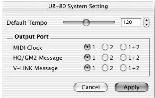
| Default Tempo | Specifies the default tempo for transmitting MIDI Timing Clock messages. When you turn on the power, Timing Clock tempo will be initialized to the setting you specify here. |
| MIDI Clock | Specify the output port for MIDI Timing Clock messages. |
| HQ/GM2 messages | Specifies the output port for messages in Synth Edit mode. |
| V-LINK messages | Specifies the output port for messages in V-LINK mode. |
- To apply the settings, click[Apply].
Pro Tools LE, Digital Performer 3
Memory Set
Verwenden Sie USR4.
| Type | Receive From | Send To |
| HUI | UR-80 1 | UR-80 1 |
Einstellungen in Digital Performer
| Schaltfläche | Tempo (BPM) |
| △ | 80 |
| ↓ | 120 |
| 145 | |
| 100 | |
| [SHIFT]+ | 20 |
| [SHIFT]+ | 180 |
| [SHIFT]+ | 250 |
| [SHIFT]+ | 60 |
TIME-Wahlscheibe
Section Track Control. p. 150
Section Master Control. p. 153
Section Audio Control. p. 155

Section Track Control
Section Master Control
Section Audio Control
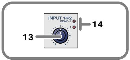
COAXIAL. Câble coaxial
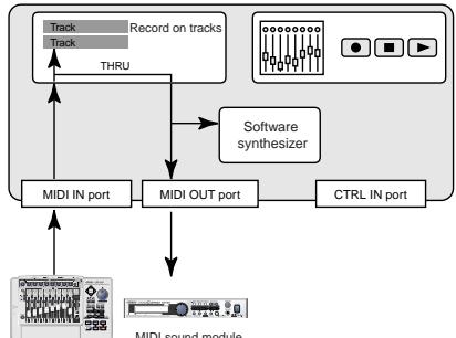
Sequencer software
UR-80
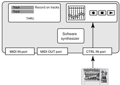
Sequencer software
UR-80
Section Track Control
Section Master Control
Boutons-curseurs
Section Track Control
Section Master Control
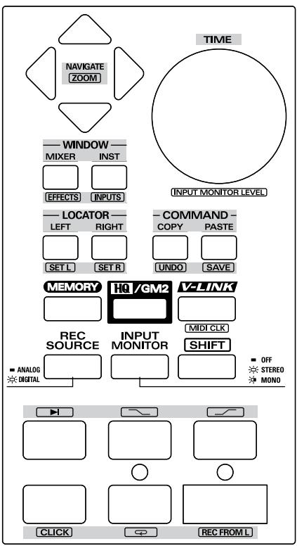
Boutons-curseurs
Section Track Control
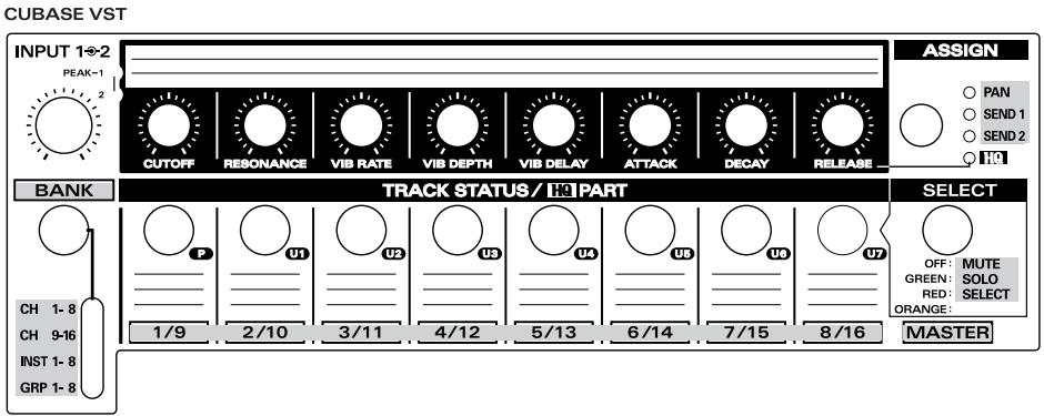
Section Master Control
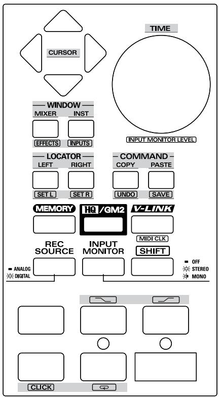
Boutons-curseurs
Section Track Control
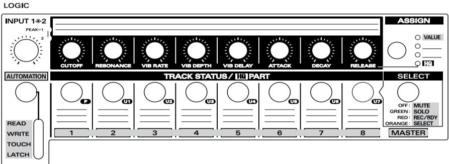
Section Master Control
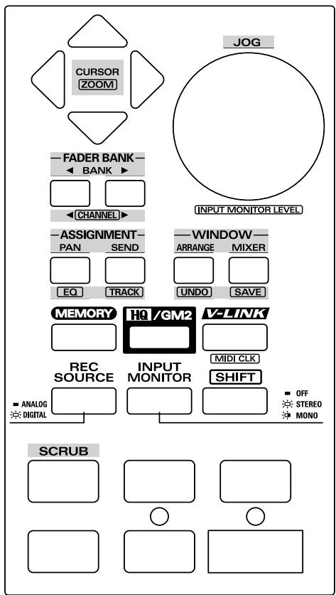
Boutons-curseurs
Pro Tools LE, Digital Performer 3
Jeude sons
Utilizez USR4.
| Type | Receive From | Send To |
| HUI | UR-80 1 | UR-80 1 |
■ Réglages de Digital Performer
Section Track Control
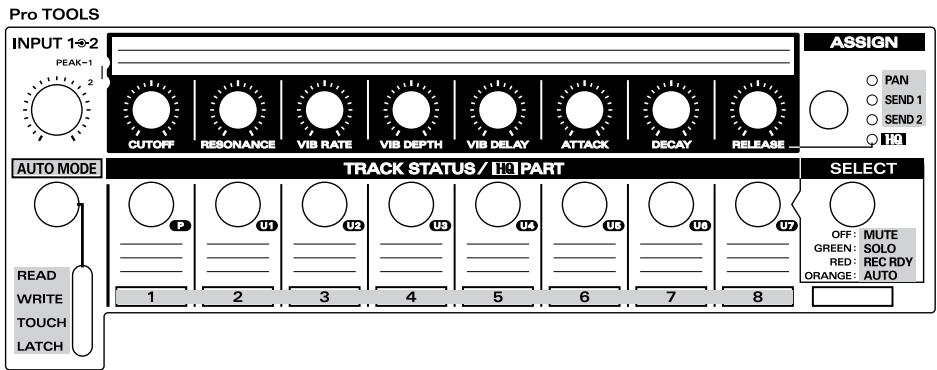
Section Master Control

Boutons-curseurs
You've asked desirably of the reason version 2.0 ou ultérieure.
Section Track Control
REASON
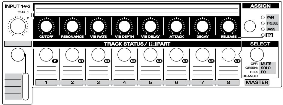
Section Master Control

Boutons-curseurs
| Bouton | Tempo (BPM) |
| △ | 80 |
| 120 | |
| 145 | |
| 100 | |
| [SHIFT]+ | 20 |
| [SHIFT]+ | 180 |
| [SHIFT]+ | 250 |
| [SHIFT]+ | 60 |
Composition TIME
2. Section H-ACTIVITY
Partie relativedecisions
Pannello principale
Pro Tools LE, Digital Performer 3
Patch di memoria
| Type | Receive From | Send to |
| HUI | UR-80 1 | UR-80 1 |
| Pulsante | Tempo (BPM) |
| △ | 80 |
| ↓ | 120 |
| 145 | |
| 100 | |
| [SHIFT]+ | 20 |
| [SHIFT]+ | 180 |
| [SHIFT]+ | 250 |
| [SHIFT]+ | 60 |
Manopola TIME
COAXIAL... Cable coaxial
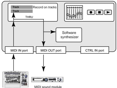
Sequencer software
UR-80
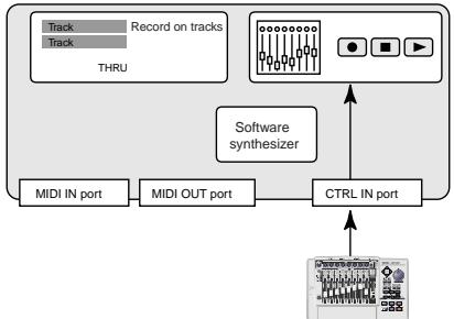
Sequencer software
UR-80
Pro Tools LE, Digital Performer 3
Conjunto de memoria
Debe utilizes USR4.
| Type | Receive From | Send To |
| HUI | UR-80 1 | UR-80 1 |
System-related settings
Restoring the factory settings (Factory Reset)
- While holding down the STOP button and MEMORY button, turn on the power. The REC button LED will blink.
-
Press the REC button to initialize the settings.
-
If you perform any operation other than pressing the REC button, the UR-80 will return to normal operation without being initialized.
| Initialized setting | Initial value |
| User memory sets | — |
| V-LINK initialization message | — |
| MIDI Timing Clock on/off switch | OFF |
| Default Tempo | 120 |
| MIDI Timing Clock output port | 1 |
| HQ/GM2 output port | 1 |
| V-LINK message output port | 1 |
| Driver mode | Original driver mode |
| REC SOURCE | ANALOG |
| INOPUT MONITOR | OFF |
Switching the Driver Mode
You can switch the mode (type) of driver used for USB connection.
With the factory settings, Original Driver Mode is selected. Normally, you should use Original Driver Mode.
| Original Driver Mode | Turn on the power of the UR-80 while holding down the HQ/GM2 button |
| Standard Driver Mode | Turn on the power of the UR-80 while holding down the V-LINK button |
- If the UR-80's sampling frequency is set to 96 kHz REC or 96 kHz PLAY, it cannot be started up in Standard Driver Mode.
Checking the Driver Mode
If Original Driver Mode is selected, the HQ/GM2 button LED will light for approximately two-seconds when you turn on the power.
If Standard Driver Mode is selected, the V-LINK button LED will light for approximately two-seconds when you turn on the power.
Mac OS 9 series users
If you are using a Sound Manager-compatible application, use the UR-80 in Standard Driver Mode. If you start up in Standard Driver Mode, a message like the following will appear.
"Cannot use the driver required by USB device "UR-80". Search for a driver on the Internet?"
If this message appears, click [Cancel]. You will be able to use only the UR-80's audio functionality.
- You cannot use UR-80 Editor in Standard Driver Mode.
Memory sets
The parameters assigned to each controller are listed below. For details on how to edit these settings, refer to "Controlling your software (p. 32)."
- PRESET MEMORY (SONAR) PARAMETER LIST (p. 349)
- USR1 MEMORY (Cubase SX) PARAMETER LIST (p. 352)
- USR2 MEMORY (Cubase VST) PARAMETER LIST (p. 355)
- USR3 MEMORY (Logic) PARAMETER LIST (p. 358)
- USR4 MEMORY (Pro Tools LE / Digital Performer) PARAMETER LIST .....(p. 361)
- USR5 MEMORY (Reason) PARAMETER LIST (p. 365)
- USR6 MCR-8 Mode4-A/1-8 PARAMETER LIST (p. 368)
- USR7 MCR-8 Mode4-B/9-16 PARAMETER LIST (p. 370)
PRESET MEMORY (SONAR) PARAMETER LIST
INITIALMESSAGE
BF 7F 7F
PORT
2
H-ACTIVITY
OFF
| - | PARAMETER | OUTPUTMESSAGE | RANGE | CH | PORT | MODE |
| TRACK CONTROL 1 [PAN] | Track 1 Pan | CC 72(48) | 0(00) - 127(7F) | 16 | 2 | - |
| TRACK CONTROL 2 [PAN] | Track 2 Pan | CC 73(49) | 0(00) - 127(7F) | 16 | 2 | - |
| TRACK CONTROL 3 [PAN] | Track 3 Pan | CC 74(4A) | 0(00) - 127(7F) | 16 | 2 | - |
| TRACK CONTROL 4 [PAN] | Track 4 Pan | CC 75(4B) | 0(00) - 127(7F) | 16 | 2 | - |
| TRACK CONTROL 5 [PAN] | Track 5 Pan | CC 76(4C) | 0(00) - 127(7F) | 16 | 2 | - |
| TRACK CONTROL 6 [PAN] | Track 6 Pan | CC 77(4D) | 0(00) - 127(7F) | 16 | 2 | - |
| TRACK CONTROL 7 [PAN] | Track 7 Pan | CC 78(4E) | 0(00) - 127(7F) | 16 | 2 | - |
| TRACK CONTROL 8 [PAN] | Track 8 Pan | CC 79(4F) | 0(00) - 127(7F) | 16 | 2 | - |
| TRACK CONTROL 1 [SEND 1] | Track 1 Aux1 Send Level | CC 72(48) | 0(00) - 127(7F) | 15 | 2 | - |
| TRACK CONTROL 2 [SEND 1] | Track 2 Aux1 Send Level | CC 73(49) | 0(00) - 127(7F) | 15 | 2 | - |
| TRACK CONTROL 3 [SEND 1] | Track 3 Aux1 Send Level | CC 74(4A) | 0(00) - 127(7F) | 15 | 2 | - |
| TRACK CONTROL 4 [SEND 1] | Track 4 Aux1 Send Level | CC 75(4B) | 0(00) - 127(7F) | 15 | 2 | - |
| TRACK CONTROL 5 [SEND 1] | Track 5 Aux1 Send Level | CC 76(4C) | 0(00) - 127(7F) | 15 | 2 | - |
| TRACK CONTROL 6 [SEND 1] | Track 6 Aux1 Send Level | CC 77(4D) | 0(00) - 127(7F) | 15 | 2 | - |
| TRACK CONTROL 7 [SEND 1] | Track 7 Aux1 Send Level | CC 78(4E) | 0(00) - 127(7F) | 15 | 2 | - |
| TRACK CONTROL 8 [SEND 1] | Track 8 Aux1 Send Level | CC 79(4F) | 0(00) - 127(7F) | 15 | 2 | - |
| TRACK CONTROL 1 [SEND 2] | Track 1 Aux2 Send Level | CC 72(48) | 0(00) - 127(7F) | 14 | 2 | - |
| TRACK CONTROL 2 [SEND 2] | Track 2 Aux2 Send Level | CC 73(49) | 0(00) - 127(7F) | 14 | 2 | - |
| TRACK CONTROL 3 [SEND 2] | Track 3 Aux2 Send Level | CC 74(4A) | 0(00) - 127(7F) | 14 | 2 | - |
| TRACK CONTROL 4 [SEND 2] | Track 4 Aux2 Send Level | CC 75(4B) | 0(00) - 127(7F) | 14 | 2 | - |
| TRACK CONTROL 5 [SEND 2] | Track 5 Aux2 Send Level | CC 76(4C) | 0(00) - 127(7F) | 14 | 2 | - |
| TRACK CONTROL 6 [SEND 2] | Track 6 Aux2 Send Level | CC 77(4D) | 0(00) - 127(7F) | 14 | 2 | - |
| TRACK CONTROL 7 [SEND 2] | Track 7 Aux2 Send Level | CC 78(4E) | 0(00) - 127(7F) | 14 | 2 | - |
| TRACK CONTROL 8 [SEND 2] | Track 8 Aux2 Send Level | CC 79(4F) | 0(00) - 127(7F) | 14 | 2 | - |
| TRACK STATUS 1 [MUTE] | Track 1 Mute | CC 40(28) | 0(00) / 127(7F) | 16 | 2 | UNLATCH |
| TRACK STATUS 2 [MUTE] | Track 2 Mute | CC 41(29) | 0(00) / 127(7F) | 16 | 2 | UNLATCH |
| TRACK STATUS 3 [MUTE] | Track 3 Mute | CC 42(2A) | 0(00) / 127(7F) | 16 | 2 | UNLATCH |
| TRACK STATUS 4 [MUTE] | Track 4 Mute | CC 43(2B) | 0(00) / 127(7F) | 16 | 2 | UNLATCH |
| TRACK STATUS 5 [MUTE] | Track 5 Mute | CC 44(2C) | 0(00) / 127(7F) | 16 | 2 | UNLATCH |
| TRACK STATUS 6 [MUTE] | Track 6 Mute | CC 45(2D) | 0(00) / 127(7F) | 16 | 2 | UNLATCH |
| TRACK STATUS 7 [MUTE] | Track 7 Mute | CC 46(2E) | 0(00) / 127(7F) | 16 | 2 | UNLATCH |
| TRACK STATUS 8 [MUTE] | Track 8 Mute | CC 47(2F) | 0(00) / 127(7F) | 16 | 2 | UNLATCH |
| TRACK STATUS 1 [SOLO] | Track 1 Solo | CC 0(00) | 0(00) / 127(7F) | 16 | 2 | UNLATCH |
| TRACK STATUS 2 [SOLO] | Track 2 Solo | CC 1(01) | 0(00) / 127(7F) | 16 | 2 | UNLATCH |
| TRACK STATUS 3 [SOLO] | Track 3 Solo | CC 2(02) | 0(00) / 127(7F) | 16 | 2 | UNLATCH |
| TRACK STATUS 4 [SOLO] | Track 4 Solo | CC 3(03) | 0(00) / 127(7F) | 16 | 2 | UNLATCH |
| TRACK STATUS 5 [SOLO] | Track 5 Solo | CC 4(04) | 0(00) / 127(7F) | 16 | 2 | UNLATCH |
| TRACK STATUS 6 [SOLO] | Track 6 Solo | CC 5(05) | 0(00) / 127(7F) | 16 | 2 | UNLATCH |
| TRACK STATUS 7 [SOLO] | Track 7 Solo | CC 6(06) | 0(00) / 127(7F) | 16 | 2 | UNLATCH |
| TRACK STATUS 8 [SOLO] | Track 8 Solo | CC 7(07) | 0(00) / 127(7F) | 16 | 2 | UNLATCH |
| TRACK STATUS 1 [REC] | Track 1 Record Arm | CC 40(28) | 0(00) / 127(7F) | 15 | 2 | UNLATCH |
| TRACK STATUS 2 [REC] | Track 2 Record Arm | CC 41(29) | 0(00) / 127(7F) | 15 | 2 | UNLATCH |
| TRACK STATUS 3 [REC] | Track 3 Record Arm | CC 42(2A) | 0(00) / 127(7F) | 15 | 2 | UNLATCH |
| TRACK STATUS 4 [REC] | Track 4 Record Arm | CC 43(2B) | 0(00) / 127(7F) | 15 | 2 | UNLATCH |
| TRACK STATUS 5 [REC] | Track 5 Record Arm | CC 44(2C) | 0(00) / 127(7F) | 15 | 2 | UNLATCH |
| TRACK STATUS 6 [REC] | Track 6 Record Arm | CC 45(2D) | 0(00) / 127(7F) | 15 | 2 | UNLATCH |
| TRACK STATUS 7 [REC] | Track 7 Record Arm | CC 46(2E) | 0(00) / 127(7F) | 15 | 2 | UNLATCH |
| TRACK STATUS 8 [REC] | Track 8 Record Arm | CC 47(2F) | 0(00) / 127(7F) | 15 | 2 | UNLATCH |
| TRACK STATUS 1 [AUTO] | Track 1 Write Arm | CC 0(00) | 0(00) / 127(7F) | 15 | 2 | UNLATCH |
| TRACK STATUS 2 [AUTO] | Track 2 Write Arm | CC 1(01) | 0(00) / 127(7F) | 15 | 2 | UNLATCH |
| TRACK STATUS 3 [AUTO] | Track 3 Write Arm | CC 2(02) | 0(00) / 127(7F) | 15 | 2 | UNLATCH |
| TRACK STATUS 4 [AUTO] | Track 4 Write Arm | CC 3(03) | 0(00) / 127(7F) | 15 | 2 | UNLATCH |
| TRACK STATUS 5 [AUTO] | Track 5 Write Arm | CC 4(04) | 0(00) / 127(7F) | 15 | 2 | UNLATCH |
| TRACK STATUS 6 [AUTO] | Track 6 Write Arm | CC 5(05) | 0(00) / 127(7F) | 15 | 2 | UNLATCH |
| TRACK STATUS 7 [AUTO] | Track 7 Write Arm | CC 6(06) | 0(00) / 127(7F) | 15 | 2 | UNLATCH |
| TRACK STATUS 8 [AUTO] | Track 8 Write Arm | CC 7(07) | 0(00) / 127(7F) | 15 | 2 | UNLATCH |
| TRACK FADER 1 | Track 1 Volume | CC 64(40) | 0(00) - 127(7F) | 16 | 2 | - |
| TRACK FADER 2 | Track 2 Volume | CC 65(41) | 0(00) - 127(7F) | 16 | 2 | - |
| TRACK FADER 3 | Track 3 Volume | CC 66(42) | 0(00) - 127(7F) | 16 | 2 | - |
| TRACK FADER 4 | Track 4 Volume | CC 67(43) | 0(00) - 127(7F) | 16 | 2 | - |
| TRACK FADER 5 | Track 5 Volume | CC 68(44) | 0(00) - 127(7F) | 16 | 2 | - |
| TRACK FADER 6 | Track 6 Volume | CC 69(45) | 0(00) - 127(7F) | 16 | 2 | - |
| TRACK FADER 7 | Track 7 Volume | CC 70(46) | 0(00) - 127(7F) | 16 | 2 | - |
| TRACK FADER 8 | Track 8 Volume | CC 71(47) | 0(00) - 127(7F) | 16 | 2 | - |
| MASTER FADER | Master Volume | CC 81(51) | 0(00) - 127(7F) | 16 | 2 | - |
| TRACK GROUP 1 - 8 | Base Track = 1 | CC 97(61) | 0(00) - 127(7F) | 16 | 2 | UNLATCH |
| TRACK GROUP 9 - 16 | Base Track = 9 | CC 98(62) | 0(00) - 127(7F) | 16 | 2 | UNLATCH |
| TRACK GROUP 17 - 24 | Base Track = 17 | CC 99(63) | 0(00) - 127(7F) | 16 | 2 | UNLATCH |
| TRACK GROUP 25 - 32 | Base Track = 25 | CC 100(64) | 0(00) - 127(7F) | 16 | 2 | UNLATCH |
| JOG DIAL [TIME] | Time | CC 96(60) | 127(7F) - 1(01) | 16 | 2 | - |
| CURSOR UP | Up Arrow Key | CC 26(1A) | 0(00) / 127(7F) | 16 | 2 | UNLATCH |
| CURSOR DOWN | Down Arrow Key | CC 27(1B) | 0(00) / 127(7F) | 16 | 2 | UNLATCH |
| CURSOR LEFT | Left Arrow Key | CC 28(1C) | 0(00) / 127(7F) | 16 | 2 | UNLATCH |
| CURSOR RIGHT | Right Arrow Key | CC 29(1D) | 0(00) / 127(7F) | 16 | 2 | UNLATCH |
| FUNCTION 1 [MIXER] | Open Console View | CC 10(0A) | 0(00) / 127(7F) | 16 | 2 | UNLATCH |
| FUNCTION 2 [INST] | Open Synth Rack | CC 11(0B) | 0(00) / 127(7F) | 16 | 2 | UNLATCH |
| FUNCTION 3 [PREV] | Go Previous Marker | CC 12(0C) | 0(00) / 127(7F) | 16 | 2 | UNLATCH |
| FUNCTION 4 [NEXT] | Go Next Marker | CC 13(0D) | 0(00) / 127(7F) | 16 | 2 | UNLATCH |
| FUNCTION 5 [UNDO] | Undo | CC 14(0E) | 0(00) / 127(7F) | 16 | 2 | UNLATCH |
| FUNCTION 6 [SAVE AS] | Save as... | CC 15(0F) | 0(00) / 127(7F) | 16 | 2 | UNLATCH |
| TRANSPORT [RTZ] | Rewind | CC 9(09) | 0(00) / 127(7F) | 16 | 2 | UNLATCH |
| TRANSPORT [REW] | Go Previous Measure | CC 19(13) | 0(00) / 127(7F) | 16 | 2 | UNLATCH |
| TRANSPORT [FWD] | Go Next Measure | CC 20(14) | 0(00) / 127(7F) | 16 | 2 | UNLATCH |
| TRANSPORT [STOP] | Stop | CC 21(15) | 0(00) / 127(7F) | 16 | 2 | UNLATCH |
| TRANSPORT [PLAY] | Play | CC 22(16) | 0(00) / 127(7F) | 16 | 2 | UNLATCH |
| TRANSPORT [REC] | Record | CC 23(17) | 0(00) / 127(7F) | 16 | 2 | UNLATCH |
| SHIFT + CURSOR UP | Vertical Zoom Out | CC 26(1A) | 0(00) / 127(7F) | 15 | 2 | UNLATCH |
| SHIFT + CURSOR DOWN | Vertical Zoom In | CC 27(1B) | 0(00) / 127(7F) | 15 | 2 | UNLATCH |
| SHIFT + CURSOR LEFT | Horizontal Zoom Out | CC 28(1C) | 0(00) / 127(7F) | 15 | 2 | UNLATCH |
| SHIFT + CURSOR RIGHT | Horizontal Zoom In | CC 29(1D) | 0(00) / 127(7F) | 15 | 2 | UNLATCH |
| SHIFT + FUNCTION 1 [MIXER] | Next Window | CC 10(0A) | 0(00) / 127(7F) | 15 | 2 | UNLATCH |
| SHIFT + FUNCTION 2 [INST] | Close Window | CC 11(0B) | 0(00) / 127(7F) | 15 | 2 | UNLATCH |
| SHIFT + FUNCTION 3 [PREV] | Insert Marker | CC 12(0C) | 0(00) / 127(7F) | 15 | 2 | UNLATCH |
| SHIFT + FUNCTION 4 [NEXT] | Open Marker View | CC 13(0D) | 0(00) / 127(7F) | 15 | 2 | UNLATCH |
| SHIFT + FUNCTION 5 [UNDO] | Redo | CC 14(0E) | 0(00) / 127(7F) | 15 | 2 | UNLATCH |
| SHIFT + FUNCTION 6 [SAVE AS] | Save | CC 15(0F) | 0(00) / 127(7F) | 15 | 2 | UNLATCH |
| SHIFT + TRANSPORT [RTZ] | - | CC 9(09) | 0(00) / 127(7F) | 15 | 2 | UNLATCH |
| SHIFT + TRANSPORT [REW] | - | CC 19(13) | 0(00) / 127(7F) | 15 | 2 | UNLATCH |
| SHIFT + TRANSPORT [FWD] | - | CC 20(14) | 0(00) / 127(7F) | 15 | 2 | UNLATCH |
| SHIFT + TRANSPORT [STOP] | - | CC 21(15) | 0(00) / 127(7F) | 15 | 2 | UNLATCH |
| SHIFT + TRANSPORT [PLAY] | - | CC 22(16) | 0(00) / 127(7F) | 15 | 2 | UNLATCH |
| SHIFT + TRANSPORT [REC] | Write Automation | CC 23(17) | 0(00) / 127(7F) | 15 | 2 | UNLATCH |
| LED: TRACK STATUS 1 [MUTE] | Track 1 Mute | CC 40(28) | 0(00) / 127(7F) | 16 | - | REMOTE |
| LED: TRACK STATUS 2 [MUTE] | Track 2 Mute | CC 41(29) | 0(00) / 127(7F) | 16 | - | REMOTE |
| LED: TRACK STATUS 3 [MUTE] | Track 3 Mute | CC 42(2A) | 0(00) / 127(7F) | 16 | - | REMOTE |
| LED: TRACK STATUS 4 [MUTE] | Track 4 Mute | CC 43(2B) | 0(00) / 127(7F) | 16 | - | REMOTE |
| LED: TRACK STATUS 5 [MUTE] | Track 5 Mute | CC 44(2C) | 0(00) / 127(7F) | 16 | - | REMOTE |
| LED: TRACK STATUS 6 [MUTE] | Track 6 Mute | CC 45(2D) | 0(00) / 127(7F) | 16 | - | REMOTE |
| LED: TRACK STATUS 7 [MUTE] | Track 7 Mute | CC 46(2E) | 0(00) / 127(7F) | 16 | - | REMOTE |
| LED: TRACK STATUS 8 [MUTE] | Track 8 Mute | CC 47(2F) | 0(00) / 127(7F) | 16 | - | REMOTE |
| LED: TRACK STATUS 1 [SOLO] | Track 1 Solo | CC 0(00) | 0(00) / 127(7F) | 16 | - | REMOTE |
| LED: TRACK STATUS 2 [SOLO] | Track 2 Solo | CC 1(01) | 0(00) / 127(7F) | 16 | - | REMOTE |
| LED: TRACK STATUS 3 [SOLO] | Track 3 Solo | CC 2(02) | 0(00) / 127(7F) | 16 | - | REMOTE |
| LED: TRACK STATUS 4 [SOLO] | Track 4 Solo | CC 3(03) | 0(00) / 127(7F) | 16 | - | REMOTE |
| LED: TRACK STATUS 5 [SOLO] | Track 5 Solo | CC 4(04) | 0(00) / 127(7F) | 16 | - | REMOTE |
| LED: TRACK STATUS 6 [SOLO] | Track 6 Solo | CC 5(05) | 0(00) / 127(7F) | 16 | - | REMOTE |
| LED: TRACK STATUS 7 [SOLO] | Track 7 Solo | CC 6(06) | 0(00) / 127(7F) | 16 | - | REMOTE |
| LED: TRACK STATUS 8 [SOLO] | Track 8 Solo | CC 7(07) | 0(00) / 127(7F) | 16 | - | REMOTE |
| LED: TRACK STATUS 1 [REC] | Track 1 Record Arm | CC 40(28) | 0(00) / 127(7F) | 15 | - | REMOTE |
| LED: TRACK STATUS 2 [REC] | Track 2 Record Arm | CC 41(29) | 0(00) / 127(7F) | 15 | - | REMOTE |
| LED: TRACK STATUS 3 [REC] | Track 3 Record Arm | CC 42(2A) | 0(00) / 127(7F) | 15 | - | REMOTE |
| LED: TRACK STATUS 4 [REC] | Track 4 Record Arm | CC 43(2B) | 0(00) / 127(7F) | 15 | - | REMOTE |
| LED: TRACK STATUS 5 [REC] | Track 5 Record Arm | CC 44(2C) | 0(00) / 127(7F) | 15 | - | REMOTE |
| LED: TRACK STATUS 6 [REC] | Track 6 Record Arm | CC 45(2D) | 0(00) / 127(7F) | 15 | - | REMOTE |
| LED: TRACK STATUS 7 [REC] | Track 7 Record Arm | CC 46(2E) | 0(00) / 127(7F) | 15 | - | REMOTE |
| LED: TRACK STATUS 8 [REC] | Track 8 Record Arm | CC 47(2F) | 0(00) / 127(7F) | 15 | - | REMOTE |
| LED: TRACK STATUS 1 [AUTO] | Track 1 Write Arm | CC 0(00) | 0(00) / 127(7F) | 15 | - | REMOTE |
| LED: TRACK STATUS 2 [AUTO] | Track 2 Write Arm | CC 1(01) | 0(00) / 127(7F) | 15 | - | REMOTE |
| LED: TRACK STATUS 3 [AUTO] | Track 3 Write Arm | CC 2(02) | 0(00) / 127(7F) | 15 | - | REMOTE |
| LED: TRACK STATUS 4 [AUTO] | Track 4 Write Arm | CC 3(03) | 0(00) / 127(7F) | 15 | - | REMOTE |
| LED: TRACK STATUS 5 [AUTO] | Track 5 Write Arm | CC 4(04) | 0(00) / 127(7F) | 15 | - | REMOTE |
| LED: TRACK STATUS 6 [AUTO] | Track 6 Write Arm | CC 5(05) | 0(00) / 127(7F) | 15 | - | REMOTE |
| LED: TRACK STATUS 7 [AUTO] | Track 7 Write Arm | CC 6(06) | 0(00) / 127(7F) | 15 | - | REMOTE |
| LED: TRACK STATUS 8 [AUTO] | Track 8 Write Arm | CC 7(07) | 0(00) / 127(7F) | 15 | - | REMOTE |
| LED: TRANSPORT [PLAY] | Play | CC 22(16) | 0(00) / 127(7F) | 16 | - | REMOTE |
| LED: TRANSPORT [REC] | Record | CC 23(17) | 0(00) / 127(7F) | 16 | - | REMOTE |
USR1 MEMORY (Cubase SX) PARAMETER LIST
INITIALMESSAGE
BE 61 7F BE 62 7F
PORT
2
H-ACTIVITY
OFF
| - | PARAMETER | OUTPUTMESSAGE | RANGE | CH | PORT | MODE |
| TRACK CONTROL 1 [PAN] | Channel 1 Pan Left-Right | CC 72(48) | 0(00) - 127(7F) | 16 | 2 | - |
| TRACK CONTROL 2 [PAN] | Channel 2 Pan Left-Right | CC 73(49) | 0(00) - 127(7F) | 16 | 2 | - |
| TRACK CONTROL 3 [PAN] | Channel 3 Pan Left-Right | CC 74(4A) | 0(00) - 127(7F) | 16 | 2 | - |
| TRACK CONTROL 4 [PAN] | Channel 4 Pan Left-Right | CC 75(4B) | 0(00) - 127(7F) | 16 | 2 | - |
| TRACK CONTROL 5 [PAN] | Channel 5 Pan Left-Right | CC 76(4C) | 0(00) - 127(7F) | 16 | 2 | - |
| TRACK CONTROL 6 [PAN] | Channel 6 Pan Left-Right | CC 77(4D) | 0(00) - 127(7F) | 16 | 2 | - |
| TRACK CONTROL 7 [PAN] | Channel 7 Pan Left-Right | CC 78(4E) | 0(00) - 127(7F) | 16 | 2 | - |
| TRACK CONTROL 8 [PAN] | Channel 8 Pan Left-Right | CC 79(4F) | 0(00) - 127(7F) | 16 | 2 | - |
| TRACK CONTROL 1 [SEND 1] | Channel 1 Send1 Level | CC 72(48) | 0(00) - 127(7F) | 15 | 2 | - |
| TRACK CONTROL 2 [SEND 1] | Channel 2 Send1 Level | CC 73(49) | 0(00) - 127(7F) | 15 | 2 | - |
| TRACK CONTROL 3 [SEND 1] | Channel 3 Send1 Level | CC 74(4A) | 0(00) - 127(7F) | 15 | 2 | - |
| TRACK CONTROL 4 [SEND 1] | Channel 4 Send1 Level | CC 75(4B) | 0(00) - 127(7F) | 15 | 2 | - |
| TRACK CONTROL 5 [SEND 1] | Channel 5 Send1 Level | CC 76(4C) | 0(00) - 127(7F) | 15 | 2 | - |
| TRACK CONTROL 6 [SEND 1] | Channel 6 Send1 Level | CC 77(4D) | 0(00) - 127(7F) | 15 | 2 | - |
| TRACK CONTROL 7 [SEND 1] | Channel 7 Send1 Level | CC 78(4E) | 0(00) - 127(7F) | 15 | 2 | - |
| TRACK CONTROL 8 [SEND 1] | Channel 8 Send1 Level | CC 79(4F) | 0(00) - 127(7F) | 15 | 2 | - |
| TRACK CONTROL 1 [SEND 2] | Channel 1 Send2 Level | CC 72(48) | 0(00) - 127(7F) | 14 | 2 | - |
| TRACK CONTROL 2 [SEND 2] | Channel 2 Send2 Level | CC 73(49) | 0(00) - 127(7F) | 14 | 2 | - |
| TRACK CONTROL 3 [SEND 2] | Channel 3 Send2 Level | CC 74(4A) | 0(00) - 127(7F) | 14 | 2 | - |
| TRACK CONTROL 4 [SEND 2] | Channel 4 Send2 Level | CC 75(4B) | 0(00) - 127(7F) | 14 | 2 | - |
| TRACK CONTROL 5 [SEND 2] | Channel 5 Send2 Level | CC 76(4C) | 0(00) - 127(7F) | 14 | 2 | - |
| TRACK CONTROL 6 [SEND 2] | Channel 6 Send2 Level | CC 77(4D) | 0(00) - 127(7F) | 14 | 2 | - |
| TRACK CONTROL 7 [SEND 2] | Channel 7 Send2 Level | CC 78(4E) | 0(00) - 127(7F) | 14 | 2 | - |
| TRACK CONTROL 8 [SEND 2] | Channel 8 Send2 Level | CC 79(4F) | 0(00) - 127(7F) | 14 | 2 | - |
| TRACK STATUS 1 [MUTE] | Channel 1 Mute | CC 40(28) | 0(00) / 127(7F) | 16 | 2 | UNLATCH |
| TRACK STATUS 2 [MUTE] | Channel 2 Mute | CC 41(29) | 0(00) / 127(7F) | 16 | 2 | UNLATCH |
| TRACK STATUS 3 [MUTE] | Channel 3 Mute | CC 42(2A) | 0(00) / 127(7F) | 16 | 2 | UNLATCH |
| TRACK STATUS 4 [MUTE] | Channel 4 Mute | CC 43(2B) | 0(00) / 127(7F) | 16 | 2 | UNLATCH |
| TRACK STATUS 5 [MUTE] | Channel 5 Mute | CC 44(2C) | 0(00) / 127(7F) | 16 | 2 | UNLATCH |
| TRACK STATUS 6 [MUTE] | Channel 6 Mute | CC 45(2D) | 0(00) / 127(7F) | 16 | 2 | UNLATCH |
| TRACK STATUS 7 [MUTE] | Channel 7 Mute | CC 46(2E) | 0(00) / 127(7F) | 16 | 2 | UNLATCH |
| TRACK STATUS 8 [MUTE] | Channel 8 Mute | CC 47(2F) | 0(00) / 127(7F) | 16 | 2 | UNLATCH |
| TRACK STATUS 1 [SOLO] | Channel 1 Solo | CC 0(00) | 0(00) / 127(7F) | 16 | 2 | UNLATCH |
| TRACK STATUS 2 [SOLO] | Channel 2 Solo | CC 1(01) | 0(00) / 127(7F) | 16 | 2 | UNLATCH |
| TRACK STATUS 3 [SOLO] | Channel 3 Solo | CC 2(02) | 0(00) / 127(7F) | 16 | 2 | UNLATCH |
| TRACK STATUS 4 [SOLO] | Channel 4 Solo | CC 3(03) | 0(00) / 127(7F) | 16 | 2 | UNLATCH |
| TRACK STATUS 5 [SOLO] | Channel 5 Solo | CC 4(04) | 0(00) / 127(7F) | 16 | 2 | UNLATCH |
| TRACK STATUS 6 [SOLO] | Channel 6 Solo | CC 5(05) | 0(00) / 127(7F) | 16 | 2 | UNLATCH |
| TRACK STATUS 7 [SOLO] | Channel 7 Solo | CC 6(06) | 0(00) / 127(7F) | 16 | 2 | UNLATCH |
| TRACK STATUS 8 [SOLO] | Channel 8 Solo | CC 7(07) | 0(00) / 127(7F) | 16 | 2 | UNLATCH |
| TRACK STATUS 1 [REC] | Channel 1 Read | CC 40(28) | 0(00) / 127(7F) | 15 | 2 | UNLATCH |
| TRACK STATUS 2 [REC] | Channel 2 Read | CC 41(29) | 0(00) / 127(7F) | 15 | 2 | UNLATCH |
| TRACK STATUS 3 [REC] | Channel 3 Read | CC 42(2A) | 0(00) / 127(7F) | 15 | 2 | UNLATCH |
| TRACK STATUS 4 [REC] | Channel 4 Read | CC 43(2B) | 0(00) / 127(7F) | 15 | 2 | UNLATCH |
| TRACK STATUS 5 [REC] | Channel 5 Read | CC 44(2C) | 0(00) / 127(7F) | 15 | 2 | UNLATCH |
| TRACK STATUS 6 [REC] | Channel 6 Read | CC 45(2D) | 0(00) / 127(7F) | 15 | 2 | UNLATCH |
| TRACK STATUS 7 [REC] | Channel 7 Read | CC 46(2E) | 0(00) / 127(7F) | 15 | 2 | UNLATCH |
| TRACK STATUS 8 [REC] | Channel 8 Read | CC 47(2F) | 0(00) / 127(7F) | 15 | 2 | UNLATCH |
| TRACK STATUS 1 [AUTO] | Channel 1 Write | CC 0(00) | 0(00) / 127(7F) | 15 | 2 | UNLATCH |
| TRACK STATUS 2 [AUTO] | Channel 2 Write | CC 1(01) | 0(00) / 127(7F) | 15 | 2 | UNLATCH |
| TRACK STATUS 3 [AUTO] | Channel 3 Write | CC 2(02) | 0(00) / 127(7F) | 15 | 2 | UNLATCH |
| TRACK STATUS 4 [AUTO] | Channel 4 Write | CC 3(03) | 0(00) / 127(7F) | 15 | 2 | UNLATCH |
| TRACK STATUS 5 [AUTO] | Channel 5 Write | CC 4(04) | 0(00) / 127(7F) | 15 | 2 | UNLATCH |
| TRACK STATUS 6 [AUTO] | Channel 6 Write | CC 5(05) | 0(00) / 127(7F) | 15 | 2 | UNLATCH |
| TRACK STATUS 7 [AUTO] | Channel 7 Write | CC 6(06) | 0(00) / 127(7F) | 15 | 2 | UNLATCH |
| TRACK STATUS 8 [AUTO] | Channel 8 Write | CC 7(07) | 0(00) / 127(7F) | 15 | 2 | UNLATCH |
| TRACK FADER 1 | Channel 1 Volume | CC 64(40) | 0(00) - 127(7F) | 16 | 2 | - |
| TRACK FADER 2 | Channel 2 Volume | CC 65(41) | 0(00) - 127(7F) | 16 | 2 | - |
| TRACK FADER 3 | Channel 3 Volume | CC 66(42) | 0(00) - 127(7F) | 16 | 2 | - |
| TRACK FADER 4 | Channel 4 Volume | CC 67(43) | 0(00) - 127(7F) | 16 | 2 | - |
| TRACK FADER 5 | Channel 5 Volume | CC 68(44) | 0(00) - 127(7F) | 16 | 2 | - |
| TRACK FADER 6 | Channel 6 Volume | CC 69(45) | 0(00) - 127(7F) | 16 | 2 | - |
| TRACK FADER 7 | Channel 7 Volume | CC 70(46) | 0(00) - 127(7F) | 16 | 2 | - |
| TRACK FADER 8 | Channel 8 Volume | CC 71(47) | 0(00) - 127(7F) | 16 | 2 | - |
| MASTER FADER | Master Gain | CC 81(51) | 0(00) - 127(7F) | 16 | 2 | - |
| TRACK GROUP 1 - 8 | "Remote Bank " Ch. 1-8"" | CC 97(61) | 0(00) - 127(7F) | 16 | 2 | UNLATCH |
| TRACK GROUP 9 - 16 | "Remote Bank " Ch. 9-16"" | CC 98(62) | 0(00) - 127(7F) | 16 | 2 | UNLATCH |
| TRACK GROUP 17 - 24 | "Remote Bank " Ch. 17-24"" | CC 99(63) | 0(00) - 127(7F) | 16 | 2 | UNLATCH |
| TRACK GROUP 25 - 32 | "Remote Bank " Ch. 25-32"" | CC 100(64) | 0(00) - 127(7F) | 16 | 2 | UNLATCH |
| JOG DIAL [TIME] | Time | CC 96(60) | 127(7F) - 1(01) | 16 | 2 | - |
| CURSOR UP | Navigate Up | CC 26(1A) | 0(00) / 127(7F) | 16 | 2 | UNLATCH |
| CURSOR DOWN | Navigate Down | CC 27(1B) | 0(00) / 127(7F) | 16 | 2 | UNLATCH |
| CURSOR LEFT | Navigate Left | CC 28(1C) | 0(00) / 127(7F) | 16 | 2 | UNLATCH |
| CURSOR RIGHT | Navigate Right | CC 29(1D) | 0(00) / 127(7F) | 16 | 2 | UNLATCH |
| FUNCTION 1 [MIXER] | Mixer | CC 10(0A) | 0(00) / 127(7F) | 16 | 2 | UNLATCH |
| FUNCTION 2 [INST] | VST Instruments | CC 11(0B) | 0(00) / 127(7F) | 16 | 2 | UNLATCH |
| FUNCTION 3 [PREV] | To Left Locator | CC 12(0C) | 0(00) / 127(7F) | 16 | 2 | UNLATCH |
| FUNCTION 4 [NEXT] | To Right Locator | CC 13(0D) | 0(00) / 127(7F) | 16 | 2 | UNLATCH |
| FUNCTION 5 [UNDO] | Copy | CC 14(0E) | 0(00) / 127(7F) | 16 | 2 | UNLATCH |
| FUNCTION 6 [SAVE AS] | Paste | CC 15(0F) | 0(00) / 127(7F) | 16 | 2 | UNLATCH |
| TRANSPORT [RTZ] | Return To Zero | CC 9(09) | 0(00) / 127(7F) | 16 | 2 | UNLATCH |
| TRANSPORT [REW] | Rewind | CC 19(13) | 0(00) / 127(7F) | 16 | 2 | UNLATCH |
| TRANSPORT [FWD] | Forward | CC 20(14) | 0(00) / 127(7F) | 16 | 2 | UNLATCH |
| TRANSPORT [STOP] | Stop | CC 21(15) | 0(00) / 127(7F) | 16 | 2 | UNLATCH |
| TRANSPORT [PLAY] | Start | CC 22(16) | 0(00) / 127(7F) | 16 | 2 | UNLATCH |
| TRANSPORT [REC] | Record | CC 23(17) | 0(00) / 127(7F) | 16 | 2 | UNLATCH |
| SHIFT + CURSOR UP | Zoom Out Vertical | CC 26(1A) | 0(00) / 127(7F) | 15 | 2 | UNLATCH |
| SHIFT + CURSOR DOWN | Zoom In Vertical | CC 27(1B) | 0(00) / 127(7F) | 15 | 2 | UNLATCH |
| SHIFT + CURSOR LEFT | Zoom Out | CC 28(1C) | 0(00) / 127(7F) | 15 | 2 | UNLATCH |
| SHIFT + CURSOR RIGHT | Zoom In | CC 29(1D) | 0(00) / 127(7F) | 15 | 2 | UNLATCH |
| SHIFT + FUNCTION 1 [MIXER] | VST Send Effect | CC 10(0A) | 0(00) / 127(7F) | 15 | 2 | UNLATCH |
| SHIFT + FUNCTION 2 [INST] | VST Inputs | CC 11(0B) | 0(00) / 127(7F) | 15 | 2 | UNLATCH |
| SHIFT + FUNCTION 3 [PREV] | Set Left Locator | CC 12(0C) | 0(00) / 127(7F) | 15 | 2 | UNLATCH |
| SHIFT + FUNCTION 4 [NEXT] | Set Right Locator | CC 13(0D) | 0(00) / 127(7F) | 15 | 2 | UNLATCH |
| SHIFT + FUNCTION 5 [UNDO] | Undo | CC 14(0E) | 0(00) / 127(7F) | 15 | 2 | UNLATCH |
| SHIFT + FUNCTION 6 [SAVE AS] | Save | CC 15(0F) | 0(00) / 127(7F) | 15 | 2 | UNLATCH |
| SHIFT + TRANSPORT [RTZ] | Go to End | CC 9(09) | 0(00) / 127(7F) | 15 | 2 | UNLATCH |
| SHIFT + TRANSPORT [REW] | Punch In | CC 19(13) | 0(00) / 127(7F) | 15 | 2 | UNLATCH |
| SHIFT + TRANSPORT [FWD] | Punch Out | CC 20(14) | 0(00) / 127(7F) | 15 | 2 | UNLATCH |
| SHIFT + TRANSPORT [STOP] | Metronome | CC 21(15) | 0(00) / 127(7F) | 15 | 2 | UNLATCH |
| SHIFT + TRANSPORT [PLAY] | Cycle | CC 22(16) | 0(00) / 127(7F) | 15 | 2 | UNLATCH |
| SHIFT + TRANSPORT [REC] | Record From Left Loca-tor | CC 23(17) | 0(00) / 127(7F) | 15 | 2 | UNLATCH |
| LED: TRACK STATUS 1 [MUTE] | Channel 1 Mute | CC 40(28) | 0(00) / 64(40) | 16 | - | REMOTE |
| LED: TRACK STATUS 2 [MUTE] | Channel 2 Mute | CC 41(29) | 0(00) / 64(40) | 16 | - | REMOTE |
| LED: TRACK STATUS 3 [MUTE] | Channel 3 Mute | CC 42(2A) | 0(00) / 64(40) | 16 | - | REMOTE |
| LED: TRACK STATUS 4 [MUTE] | Channel 4 Mute | CC 43(2B) | 0(00) / 64(40) | 16 | - | REMOTE |
| LED: TRACK STATUS 5 [MUTE] | Channel 5 Mute | CC 44(2C) | 0(00) / 64(40) | 16 | - | REMOTE |
| LED: TRACK STATUS 6 [MUTE] | Channel 6 Mute | CC 45(2D) | 0(00) / 64(40) | 16 | - | REMOTE |
| LED: TRACK STATUS 7 [MUTE] | Channel 7 Mute | CC 46(2E) | 0(00) / 64(40) | 16 | - | REMOTE |
| LED: TRACK STATUS 8 [MUTE] | Channel 8 Mute | CC 47(2F) | 0(00) / 64(40) | 16 | - | REMOTE |
| LED: TRACK STATUS 1 [SOLO] | Channel 1 Solo | CC 0(00) | 0(00) / 64(40) | 16 | - | REMOTE |
| LED: TRACK STATUS 2 [SOLO] | Channel 2 Solo | CC 1(01) | 0(00) / 64(40) | 16 | - | REMOTE |
| LED: TRACK STATUS 3 [SOLO] | Channel 3 Solo | CC 2(02) | 0(00) / 64(40) | 16 | - | REMOTE |
| LED: TRACK STATUS 4 [SOLO] | Channel 4 Solo | CC 3(03) | 0(00) / 64(40) | 16 | - | REMOTE |
| LED: TRACK STATUS 5 [SOLO] | Channel 5 Solo | CC 4(04) | 0(00) / 64(40) | 16 | - | REMOTE |
| LED: TRACK STATUS 6 [SOLO] | Channel 6 Solo | CC 5(05) | 0(00) / 64(40) | 16 | - | REMOTE |
| LED: TRACK STATUS 7 [SOLO] | Channel 7 Solo | CC 6(06) | 0(00) / 64(40) | 16 | - | REMOTE |
| LED: TRACK STATUS 8 [SOLO] | Channel 8 Solo | CC 7(07) | 0(00) / 64(40) | 16 | - | REMOTE |
| LED: TRACK STATUS 1 [REC] | Channel 1 Read | CC 40(28) | 0(00) / 64(40) | 15 | - | REMOTE |
| LED: TRACK STATUS 2 [REC] | Channel 2 Read | CC 41(29) | 0(00) / 64(40) | 15 | - | REMOTE |
| LED: TRACK STATUS 3 [REC] | Channel 3 Read | CC 42(2A) | 0(00) / 64(40) | 15 | - | REMOTE |
| LED: TRACK STATUS 4 [REC] | Channel 4 Read | CC 43(2B) | 0(00) / 64(40) | 15 | - | REMOTE |
| LED: TRACK STATUS 5 [REC] | Channel 5 Read | CC 44(2C) | 0(00) / 64(40) | 15 | - | REMOTE |
| LED: TRACK STATUS 6 [REC] | Channel 6 Read | CC 45(2D) | 0(00) / 64(40) | 15 | - | REMOTE |
| LED: TRACK STATUS 7 [REC] | Channel 7 Read | CC 46(2E) | 0(00) / 64(40) | 15 | - | REMOTE |
| LED: TRACK STATUS 8 [REC] | Channel 8 Read | CC 47(2F) | 0(00) / 64(40) | 15 | - | REMOTE |
| LED: TRACK STATUS 1 [AUTO] | Channel 1 Write | CC 0(00) | 0(00) / 64(40) | 15 | - | REMOTE |
| LED: TRACK STATUS 2 [AUTO] | Channel 2 Write | CC 1(01) | 0(00) / 64(40) | 15 | - | REMOTE |
| LED: TRACK STATUS 3 [AUTO] | Channel 3 Write | CC 2(02) | 0(00) / 64(40) | 15 | - | REMOTE |
| LED: TRACK STATUS 4 [AUTO] | Channel 4 Write | CC 3(03) | 0(00) / 64(40) | 15 | - | REMOTE |
| LED: TRACK STATUS 5 [AUTO] | Channel 5 Write | CC 4(04) | 0(00) / 64(40) | 15 | - | REMOTE |
| LED: TRACK STATUS 6 [AUTO] | Channel 6 Write | CC 5(05) | 0(00) / 64(40) | 15 | - | REMOTE |
| LED: TRACK STATUS 7 [AUTO] | Channel 7 Write | CC 6(06) | 0(00) / 64(40) | 15 | - | REMOTE |
| LED: TRACK STATUS 8 [AUTO] | Channel 8 Write | CC 7(07) | 0(00) / 64(40) | 15 | - | REMOTE |
| LED: TRANSPORT [PLAY] | Start | CC 22(16) | 0(00) / 64(40) | 16 | - | REMOTE |
| LED: TRANSPORT [REC] | Record | CC 23(17) | 0(00) / 64(40) | 16 | - | REMOTE |
USR2 MEMORY (Cubase VST) PARAMETER LIST
INITIALMESSAGE
BE617FBE627F
PORT
2
H-ACTIVITY
OFF
| - | PARAMETER | OUTPUTMESSAGE | RANGE | CH | PORT | MODE |
| TRACK CONTROL 1 [PAN] | Channel 1 Pan Left-Right | CC 72(48) | 0(00) - 127(7F) | 16 | 2 | - |
| TRACK CONTROL 2 [PAN] | Channel 2 Pan Left-Right | CC 73(49) | 0(00) - 127(7F) | 16 | 2 | - |
| TRACK CONTROL 3 [PAN] | Channel 3 Pan Left-Right | CC 74(4A) | 0(00) - 127(7F) | 16 | 2 | - |
| TRACK CONTROL 4 [PAN] | Channel 4 Pan Left-Right | CC 75(4B) | 0(00) - 127(7F) | 16 | 2 | - |
| TRACK CONTROL 5 [PAN] | Channel 5 Pan Left-Right | CC 76(4C) | 0(00) - 127(7F) | 16 | 2 | - |
| TRACK CONTROL 6 [PAN] | Channel 6 Pan Left-Right | CC 77(4D) | 0(00) - 127(7F) | 16 | 2 | - |
| TRACK CONTROL 7 [PAN] | Channel 7 Pan Left-Right | CC 78(4E) | 0(00) - 127(7F) | 16 | 2 | - |
| TRACK CONTROL 8 [PAN] | Channel 8 Pan Left-Right | CC 79(4F) | 0(00) - 127(7F) | 16 | 2 | - |
| TRACK CONTROL 1 [SEND 1] | Channel 1 FX Send 1 Level | CC 72(48) | 0(00) - 127(7F) | 15 | 2 | - |
| TRACK CONTROL 2 [SEND 1] | Channel 2 FX Send 1 Level | CC 73(49) | 0(00) - 127(7F) | 15 | 2 | - |
| TRACK CONTROL 3 [SEND 1] | Channel 3 FX Send 1 Level | CC 74(4A) | 0(00) - 127(7F) | 15 | 2 | - |
| TRACK CONTROL 4 [SEND 1] | Channel 4 FX Send 1 Level | CC 75(4B) | 0(00) - 127(7F) | 15 | 2 | - |
| TRACK CONTROL 5 [SEND 1] | Channel 5 FX Send 1 Level | CC 76(4C) | 0(00) - 127(7F) | 15 | 2 | - |
| TRACK CONTROL 6 [SEND 1] | Channel 6 FX Send 1 Level | CC 77(4D) | 0(00) - 127(7F) | 15 | 2 | - |
| TRACK CONTROL 7 [SEND 1] | Channel 7 FX Send 1 Level | CC 78(4E) | 0(00) - 127(7F) | 15 | 2 | - |
| TRACK CONTROL 8 [SEND 1] | Channel 8 FX Send 1 Level | CC 79(4F) | 0(00) - 127(7F) | 15 | 2 | - |
| TRACK CONTROL 1 [SEND 2] | Channel 1 FX Send 2 Level | CC 72(48) | 0(00) - 127(7F) | 14 | 2 | - |
| TRACK CONTROL 2 [SEND 2] | Channel 2 FX Send 2 Level | CC 73(49) | 0(00) - 127(7F) | 14 | 2 | - |
| TRACK CONTROL 3 [SEND 2] | Channel 3 FX Send 2 Level | CC 74(4A) | 0(00) - 127(7F) | 14 | 2 | - |
| TRACK CONTROL 4 [SEND 2] | Channel 4 FX Send 2 Level | CC 75(4B) | 0(00) - 127(7F) | 14 | 2 | - |
| TRACK CONTROL 5 [SEND 2] | Channel 5 FX Send 2 Level | CC 76(4C) | 0(00) - 127(7F) | 14 | 2 | - |
| TRACK CONTROL 6 [SEND 2] | Channel 6 FX Send 2 Level | CC 77(4D) | 0(00) - 127(7F) | 14 | 2 | - |
| TRACK CONTROL 7 [SEND 2] | Channel 7 FX Send 2 Level | CC 78(4E) | 0(00) - 127(7F) | 14 | 2 | - |
| TRACK CONTROL 8 [SEND 2] | Channel 8 FX Send 2 Level | CC 79(4F) | 0(00) - 127(7F) | 14 | 2 | - |
| TRACK STATUS 1 [MUTE] | Channel 1 Mute | CC 40(28) | 0(00) / 127(7F) | 16 | 2 | UNLATCH |
| TRACK STATUS 2 [MUTE] | Channel 2 Mute | CC 41(29) | 0(00) / 127(7F) | 16 | 2 | UNLATCH |
| TRACK STATUS 3 [MUTE] | Channel 3 Mute | CC 42(2A) | 0(00) / 127(7F) | 16 | 2 | UNLATCH |
| TRACK STATUS 4 [MUTE] | Channel 4 Mute | CC 43(2B) | 0(00) / 127(7F) | 16 | 2 | UNLATCH |
| TRACK STATUS 5 [MUTE] | Channel 5 Mute | CC 44(2C) | 0(00) / 127(7F) | 16 | 2 | UNLATCH |
| TRACK STATUS 6 [MUTE] | Channel 6 Mute | CC 45(2D) | 0(00) / 127(7F) | 16 | 2 | UNLATCH |
| TRACK STATUS 7 [MUTE] | Channel 7 Mute | CC 46(2E) | 0(00) / 127(7F) | 16 | 2 | UNLATCH |
| TRACK STATUS 8 [MUTE] | Channel 8 Mute | CC 47(2F) | 0(00) / 127(7F) | 16 | 2 | UNLATCH |
| TRACK STATUS 1 [SOLO] | Channel 1 Solo | CC 0(00) | 0(00) / 127(7F) | 16 | 2 | UNLATCH |
| TRACK STATUS 2 [SOLO] | Channel 2 Solo | CC 1(01) | 0(00) / 127(7F) | 16 | 2 | UNLATCH |
| TRACK STATUS 3 [SOLO] | Channel 3 Solo | CC 2(02) | 0(00) / 127(7F) | 16 | 2 | UNLATCH |
| TRACK STATUS 4 [SOLO] | Channel 4 Solo | CC 3(03) | 0(00) / 127(7F) | 16 | 2 | UNLATCH |
| TRACK STATUS 5 [SOLO] | Channel 5 Solo | CC 4(04) | 0(00) / 127(7F) | 16 | 2 | UNLATCH |
| TRACK STATUS 6 [SOLO] | Channel 6 Solo | CC 5(05) | 0(00) / 127(7F) | 16 | 2 | UNLATCH |
| TRACK STATUS 7 [SOLO] | Channel 7 Solo | CC 6(06) | 0(00) / 127(7F) | 16 | 2 | UNLATCH |
| TRACK STATUS 8 [SOLO] | Channel 8 Solo | CC 7(07) | 0(00) / 127(7F) | 16 | 2 | UNLATCH |
| TRACK STATUS 1 [REC] | Channel 1 Select | CC 40(28) | 0(00) / 127(7F) | 15 | 2 | UNLATCH |
| TRACK STATUS 2 [REC] | Channel 2 Select | CC 41(29) | 0(00) / 127(7F) | 15 | 2 | UNLATCH |
| TRACK STATUS 3 [REC] | Channel 3 Select | CC 42(2A) | 0(00) / 127(7F) | 15 | 2 | UNLATCH |
| TRACK STATUS 4 [REC] | Channel 4 Select | CC 43(2B) | 0(00) / 127(7F) | 15 | 2 | UNLATCH |
| TRACK STATUS 5 [REC] | Channel 5 Select | CC 44(2C) | 0(00) / 127(7F) | 15 | 2 | UNLATCH |
| TRACK STATUS 6 [REC] | Channel 6 Select | CC 45(2D) | 0(00) / 127(7F) | 15 | 2 | UNLATCH |
| TRACK STATUS 7 [REC] | Channel 7 Select | CC 46(2E) | 0(00) / 127(7F) | 15 | 2 | UNLATCH |
| TRACK STATUS 8 [REC] | Channel 8 Select | CC 47(2F) | 0(00) / 127(7F) | 15 | 2 | UNLATCH |
| TRACK STATUS 1 [AUTO] | - | CC 0(00) | 0(00) / 127(7F) | 15 | 2 | UNLATCH |
| TRACK STATUS 2 [AUTO] | - | CC 1(01) | 0(00) / 127(7F) | 15 | 2 | UNLATCH |
| TRACK STATUS 3 [AUTO] | - | CC 2(02) | 0(00) / 127(7F) | 15 | 2 | UNLATCH |
| TRACK STATUS 4 [AUTO] | - | CC 3(03) | 0(00) / 127(7F) | 15 | 2 | UNLATCH |
| TRACK STATUS 5 [AUTO] | - | CC 4(04) | 0(00) / 127(7F) | 15 | 2 | UNLATCH |
| TRACK STATUS 6 [AUTO] | - | CC 5(05) | 0(00) / 127(7F) | 15 | 2 | UNLATCH |
| TRACK STATUS 7 [AUTO] | - | CC 6(06) | 0(00) / 127(7F) | 15 | 2 | UNLATCH |
| TRACK STATUS 8 [AUTO] | - | CC 7(07) | 0(00) / 127(7F) | 15 | 2 | UNLATCH |
| TRACK FADER 1 | Channel 1 Volume | CC 64(40) | 0(00) - 127(7F) | 16 | 2 | - |
| TRACK FADER 2 | Channel 2 Volume | CC 65(41) | 0(00) - 127(7F) | 16 | 2 | - |
| TRACK FADER 3 | Channel 3 Volume | CC 66(42) | 0(00) - 127(7F) | 16 | 2 | - |
| TRACK FADER 4 | Channel 4 Volume | CC 67(43) | 0(00) - 127(7F) | 16 | 2 | - |
| TRACK FADER 5 | Channel 5 Volume | CC 68(44) | 0(00) - 127(7F) | 16 | 2 | - |
| TRACK FADER 6 | Channel 6 Volume | CC 69(45) | 0(00) - 127(7F) | 16 | 2 | - |
| TRACK FADER 7 | Channel 7 Volume | CC 70(46) | 0(00) - 127(7F) | 16 | 2 | - |
| TRACK FADER 8 | Channel 8 Volume | CC 71(47) | 0(00) - 127(7F) | 16 | 2 | - |
| MASTER FADER | Master Volume | CC 81(51) | 0(00) - 127(7F) | 16 | 2 | - |
| TRACK GROUPL 1 - 8 | "Remote Bank""VSTCh. 1-8"" | CC 97(61) | 0(00) - 127(7F) | 16 | 2 | UNLATCH |
| TRACK GROUPL 9 - 16 | "Remote Bank""VSTCh. 9-16"" | CC 98(62) | 0(00) - 127(7F) | 16 | 2 | UNLATCH |
| TRACK GROUPL 17 - 24 | "Remote Bank""VSTInst. 1-8"" | CC 99(63) | 0(00) - 127(7F) | 16 | 2 | UNLATCH |
| TRACK GROUPL 25 - 32 | "Remote Bank""VSTGrp. 1-8"" | CC 100(64) | 0(00) - 127(7F) | 16 | 2 | UNLATCH |
| JOG DIAL [TIME] | Time | CC 96(60) | 127(7F) - 1(01) | 16 | 2 | - |
| CURSOR UP | Arrange - Cursor Up | 9F 00 7F BF 1A7F 9F 00 00 | - | - | 1 | UNLATCH |
| CURSOR DOWN | Arrange - Cursor Down | 9F 00 7F BF 1B7F 9F 00 00 | - | - | 1 | UNLATCH |
| CURSOR LEFT | Arrange - Cursor Left | 9F 00 7F BF 1C7F 9F 00 00 | - | - | 1 | UNLATCH |
| CURSOR RIGHT | Arrange - Cursor Right | 9F 00 7F BF 1D7F 9F 00 00 | - | - | 1 | UNLATCH |
| FUNCTION 1 [MIXER] | VST Mixer | CC 10(0A) | 0(00) / 127(7F) | 16 | 2 | UNLATCH |
| FUNCTION 2 [INST] | VST Instruments | CC 11(0B) | 0(00) / 127(7F) | 16 | 2 | UNLATCH |
| FUNCTION 3 [PREV] | To Left Locator | CC 12(0C) | 0(00) / 127(7F) | 16 | 2 | UNLATCH |
| FUNCTION 4 [NEXT] | To Right Locator | CC 13(0D) | 0(00) / 127(7F) | 16 | 2 | UNLATCH |
| FUNCTION 5 [UNDO] | Copy | CC 14(0E) | 0(00) / 127(7F) | 16 | 2 | UNLATCH |
| FUNCTION 6 [SAVE AS] | Paste | CC 15(0F) | 0(00) / 127(7F) | 16 | 2 | UNLATCH |
| TRANSPORT [RTZ] | Return to Zero | CC 9(09) | 0(00) / 127(7F) | 16 | 2 | UNLATCH |
| TRANSPORT [REW] | Rewind | CC 19(13) | 0(00) / 127(7F) | 16 | 2 | UNLATCH |
| TRANSPORT [FWD] | Forward | CC 20(14) | 0(00) / 127(7F) | 16 | 2 | UNLATCH |
| TRANSPORT [STOP] | Stop | CC 21(15) | 0(00) / 127(7F) | 16 | 2 | UNLATCH |
| TRANSPORT [PLAY] | Start | CC 22(16) | 0(00) / 127(7F) | 16 | 2 | UNLATCH |
| TRANSPORT [REC] | Record | CC 23(17) | 0(00) / 127(7F) | 16 | 2 | UNLATCH |
| SHIFT + CURSOR UP | - | CC 26(1A) | 0(00) / 127(7F) | 15 | 2 | UNLATCH |
| SHIFT + CURSOR DOWN | - | CC 27(1B) | 0(00) / 127(7F) | 15 | 2 | UNLATCH |
| SHIFT + CURSOR LEFT | - | CC 28(1C) | 0(00) / 127(7F) | 15 | 2 | UNLATCH |
| SHIFT + CURSOR RIGHT | - | CC 29(1D) | 0(00) / 127(7F) | 15 | 2 | UNLATCH |
| SHIFT + FUNCTION 1 [MIXER] | VST Effects | CC 10(0A) | 0(00) / 127(7F) | 15 | 2 | UNLATCH |
| SHIFT + FUNCTION 2 [INST] | VST Inputs | CC 11(0B) | 0(00) / 127(7F) | 15 | 2 | UNLATCH |
| SHIFT + FUNCTION 3 [PREV] | Set Left Locator | CC 12(0C) | 0(00) / 127(7F) | 15 | 2 | UNLATCH |
| SHIFT + FUNCTION 4 [NEXT] | Set Right Locator | CC 13(0D) | 0(00) / 127(7F) | 15 | 2 | UNLATCH |
| SHIFT + FUNCTION 5 [UNDO] | Undo | CC 14(0E) | 0(00) / 127(7F) | 15 | 2 | UNLATCH |
| SHIFT + FUNCTION 6 [SAVE AS] | Save | CC 15(0F) | 0(00) / 127(7F) | 15 | 2 | UNLATCH |
| SHIFT + TRANSPORT [RTZ] | - | CC 9(09) | 0(00) / 127(7F) | 15 | 2 | UNLATCH |
| SHIFT + TRANSPORT [REW] | Punch In | CC 19(13) | 0(00) / 127(7F) | 15 | 2 | UNLATCH |
| SHIFT + TRANSPORT [FWD] | Punch Out | CC 20(14) | 0(00) / 127(7F) | 15 | 2 | UNLATCH |
| SHIFT + TRANSPORT [STOP] | Click | CC 21(15) | 0(00) / 127(7F) | 15 | 2 | UNLATCH |
| SHIFT + TRANSPORT [PLAY] | Cycle | CC 22(16) | 0(00) / 127(7F) | 15 | 2 | UNLATCH |
| SHIFT + TRANSPORT 6 [SAVE AS] | Save | CC 23(17) | 0(00) / 127(7F) | 15 | 2 | UNLATCH |
| SHIFT + TRANSPORT [RTZ] | - | CC 9(09) | 0(00) / 127(7F) | 15 | 2 | UNLATCH |
| SHIFT + TRANSPORT [REW] | Punch In | CC 19(13) | 0(00) * 127(7F) | 15 | 2 | UNLATCH |
| SHIFT + TRANSPORT [FWD] | Punch Out | CC 20(14) | 0(00) / 127(7F) | 15 | 2 | UNLATCH |
| SHIFT + TRANSPORT [STOP] | Click | CC 21(15) | 0(00) / 127(7,F) | 15 | 2 | UNLATCH |
| SHIFT + TRANSPORT [PLAY] | Cycle | CC 22(16) | 0(00) / 127(7F) | 15 | 2 | UNLATCH |
| SHIFT + TRANSPORT [REC] | - | CC 23(17) | 0(00) / 127(7F) | 15 | 2 | UNLATCH |
| LED: TRACK STATUS 1 [MUTE] | Channel 1 Mute | CC 40(28) | 0(00) / 64(40) | 16 | - | REMOTE |
| LED: TRACK STATUS 2 [MUTE] | Channel 2 Mute | CC 41(29) | 0(00) / 64(40) | 16 | - | REMOTE |
| LED: TRACK STATUS 3 [MUTE] | Channel 3 Mute | CC 42(2A) | 0(00) / 64(40) | 16 | - | REMOTE |
| LED: TRACK STATUS 4 [MUTE] | Channel 4 Mute | CC 43(2B) | 0(00) / 64(40) | 16 | - | REMOTE |
| LED: TRACK STATUS 5 [MUTE] | Channel 5 Mute | CC 44(2C) | 0(00) / 64(40) | 16 | - | REMOTE |
| LED: TRACK STATUS 6 [MUTE] | Channel 6 Mute | CC 45(2D) | 0(00) / 64(40) | 16 | - | REMOTE |
| LED: TRACK STATUS 7 [MUTE] | Channel 7 Mute | CC 46(2E) | 0(00) / 64(40) | 16 | - | REMOTE |
| LED: TRACK STATUS 8 [MUTE] | Channel 8 Mute | CC 47(2F) | 0(00) / 64(40) | 16 | - | REMOTE |
| LED: TRACK STATUS 1 [SOLO] | Channel 1 Solo | CC 0(00) | 0(00) / 64(40) | 16 | - | REMOTE |
| LED: TRACK STATUS 2 [SOLO] | Channel 2 Solo | CC 1(01) | 0(00) / 64(40) | 16 | - | REMOTE |
| LED: TRACK STATUS 3 [SOLO] | Channel 3 Solo | CC 2(02) | 0(00) / 64(40) | 16 | - | REMOTE |
| LED: TRACK STATUS 4 [SOLO] | Channel 4 Solo | CC 3(03) | 0(00) / 64(40) | 16 | - | REMOTE |
| LED: TRACK STATUS 5 [SOLO] | Channel 5 Solo | CC 4(04) | 0(00) / 64(40) | 16 | - | REMOTE |
| LED: TRACK STATUS 6 [SOLO] | Channel 6 Solo | CC 5(05) | 0(00) / 64(40) | 16 | - | REMOTE |
| LED: TRACK STATUS 7 [SOLO] | Channel 7 Solo | CC 6(06) | 0(00) / 64(40) | 16 | - | REMOTE |
| LED: TRACK STATUS 8 [SOLO] | Channel 8 Solo | CC 7(07) | 0(00) / 64(40) | 16 | - | REMOTE |
| LED: TRACK STATUS 1 [REC] | Channel 1 Select | CC 40(28) | 0(00) / 64(40) | 15 | - | REMOTE |
| LED: TRACK STATUS 2 [REC] | Channel 2 Select | CC 41(29) | 0(00) / 64(40) | 15 | - | REMOTE |
| LED: TRACK STATUS 3 [REC] | Channel 3 Select | CC 42(2A) | 0(00) / 64(40) | 15 | - | REMOTE |
| LED: TRACK STATUS 4 [REC] | Channel 4 Select | CC 43(2B) | 0(00) / 64(40) | 15 | - | REMOTE |
| LED: TRACK STATUS 5 [REC] | Channel 5 Select | CC 44(2C) | 0(00) / 64(40) | 15 | - | REMOTE |
| LED: TRACK STATUS 6 [REC] | Channel 6 Select | CC 45(2D) | 0(00) / 64(40) | 15 | - | REMOTE |
| LED: TRACK STATUS 7 [REC] | Channel 7 Select | CC 46(2E) | 0(00) / 64(40) | 15 | - | REMOTE |
| LED: TRACK STATUS 8 [REC] | Channel 8 Select | CC 47(2F) | 0(00) / 64(40) | 15 | - | REMOTE |
| LED: TRACK STATUS 1 [AUTO] | - | CC 0(00) | 0(00) / 64(40) | 15 | - | REMOTE |
| LED: TRACK STATUS 2 [AUTO] | - | CC 1(01) | 0(00) / 64(40) | 15 | - | REMOTE |
| LED: TRACK STATUS 3 [AUTO] | - | CC 2(02) | 0(00) / 64(40) | 15 | - | REMOTE |
| LED: TRACK STATUS 4 [AUTO] | - | CC 3(03) | 0(00) / 64(40) | 15 | - | REMOTE |
| LED: TRACK STATUS 5 [AUTO] | - | CC 4(04) | 0(00) / 64(40) | 15 | - | REMOTE |
| LED: TRACK STATUS 6 [AUTO] | - | CC 5(05) | 0(00) / 64(40) | 15 | - | REMOTE |
| LED: TRACK STATUS 7 [AUTO] | - | CC 6(06) | 0(00) / 64(40) | 15 | - | REMOTE |
| LED: TRACK STATUS 8 [AUTO] | - | CC 7(07) | 0(00) / 64(40) | 15 | - | REMOTE |
| LED: TRANSPORT [PLAY] | Start | CC 22(16) | 0(00) / 64(40) | 16 | - | REMOTE |
| LED: TRANSPORT [REC] | Record | CC 23(17) | 0(00) / 64(40) | 16 | - | REMOTE |
USR3 MEMORY (Logic) PARAMETER LIST
INITIALMESSAGE
F0 00 00 66 10 01 48 41 31 30 36 35 39 58 6B 60 5C F7
F0 00 00 66 10 03 48 41 31 30 36 35 39 F7
PORT
2
H-ACTIVITY
OFF
| - | PARAMETER | OUTPUTMESSAGE | RANGE | CH | PORT | MODE |
| TRACK CONTROL 1 [PAN] | VALUE 1 | CC 16(10) | 65(41) - 1(01) | 1 | 2 | SHUTTLE |
| TRACK CONTROL 2 [PAN] | VALUE 2 | CC 17(11) | 65(41) - 1(01) | 1 | 2 | SHUTTLE |
| TRACK CONTROL 3 [PAN] | VALUE 3 | CC 18(12) | 65(41) - 1(01) | 1 | 2 | SHUTTLE |
| TRACK CONTROL 4 [PAN] | VALUE 4 | CC 19(13) | 65(41) - 1(01) | 1 | 2 | SHUTTLE |
| TRACK CONTROL 5 [PAN] | VALUE 5 | CC 20(14) | 65(41) - 1(01) | 1 | 2 | SHUTTLE |
| TRACK CONTROL 6 [PAN] | VALUE 6 | CC 21(15) | 65(41) - 1(01) | 1 | 2 | SHUTTLE |
| TRACK CONTROL 7 [PAN] | VALUE 7 | CC 22(16) | 65(41) - 1(01) | 1 | 2 | SHUTTLE |
| TRACK CONTROL 8 [PAN] | VALUE 8 | CC 23(17) | 65(41) - 1(01) | 1 | 2 | SHUTTLE |
| TRACK CONTROL 1 [SEND 1] | VALUE 1 | CC 16(10) | 65(41) - 1(01) | 1 | 2 | SHUTTLE |
| TRACK CONTROL 2 [SEND 1] | VALUE 2 | CC 17(11) | 65(41) - 1(01) | 1 | 2 | SHUTTLE |
| TRACK CONTROL 3 [SEND 1] | VALUE 3 | CC 18(12) | 65(41) - 1(01) | 1 | 2 | SHUTTLE |
| TRACK CONTROL 4 [SEND 1] | VALUE 4 | CC 19(13) | 65(41) - 1(01) | 1 | 2 | SHUTTLE |
| TRACK CONTROL 5 [SEND 1] | VALUE 5 | CC 20(14) | 65(41) - 1(01) | 1 | 2 | SHUTTLE |
| TRACK CONTROL 6 [SEND 1] | VALUE 6 | CC 21(15) | 65(41) - 1(01) | 1 | 2 | SHUTTLE |
| TRACK CONTROL 7 [SEND 1] | VALUE 7 | CC 22(16) | 65(41) - 1(01) | 1 | 2 | SHUTTLE |
| TRACK CONTROL 8 [SEND 1] | VALUE 8 | CC 23(17) | 65(41) - 1(01) | 1 | 2 | SHUTTLE |
| TRACK CONTROL 1 [SEND 2] | VALUE 1 | CC 16(10) | 65(41) - 1(01) | 1 | 2 | SHUTTLE |
| TRACK CONTROL 2 [SEND 2] | VALUE 2 | CC 17(11) | 65(41) - 1(01) | 1 | 2 | SHUTTLE |
| TRACK CONTROL 3 [SEND 2] | VALUE 3 | CC 18(12) | 65(41) - 1(01) | 1 | 2 | SHUTTLE |
| TRACK CONTROL 4 [SEND 2] | VALUE 4 | CC 19(13) | 65(41) - 1(01) | 1 | 2 | SHUTTLE |
| TRACK CONTROL 5 [SEND 2] | VALUE 5 | CC 20(14) | 65(41) - 1(01) | 1 | 2 | SHUTTLE |
| TRACK CONTROL 6 [SEND 2] | VALUE 6 | CC 21(15) | 65(41) - 1(01) | 1 | 2 | SHUTTLE |
| TRACK CONTROL 7 [SEND 2] | VALUE 7 | CC 22(16) | 65(41) - 1(01) | 1 | 2 | SHUTTLE |
| TRACK CONTROL 8 [SEND 2] | VALUE 8 | CC 23(17) | 65(41) - 1(01) | 1 | 2 | SHUTTLE |
| TRACK STATUS 1 [MUTE] | MUTE 1 | NOTE 16(10) | 0(00) / 127(7F) | 1 | 2 | UNLATCH |
| TRACK STATUS 2 [MUTE] | MUTE 2 | NOTE 17(11) | 0(00) / 127(7F) | 1 | 2 | UNLATCH |
| TRACK STATUS 3 [MUTE] | MUTE 3 | NOTE 18(12) | 0(00) / 127(7F) | 1 | 2 | UNLATCH |
| TRACK STATUS 4 [MUTE] | MUTE 4 | NOTE 19(13) | 0(00) / 127(7F) | 1 | 2 | UNLATCH |
| TRACK STATUS 5 [MUTE] | MUTE 5 | NOTE 20(14) | 0(00) / 127(7F) | 1 | 2 | UNLATCH |
| TRACK STATUS 6 [MUTE] | MUTE 6 | NOTE 21(15) | 0(00) / 127(7F) | 1 | 2 | UNLATCH |
| TRACK STATUS 7 [MUTE] | MUTE 7 | NOTE 22(16) | 0(00) / 127(7F) | 1 | 2 | UNLATCH |
| TRACK STATUS 8 [MUTE] | MUTE 8 | NOTE 23(17) | 0(00) / 127(7F) | 1 | 2 | UNLATCH |
| TRACK STATUS 1 [SOLO] | SOLO 1 | NOTE 8(08) | 0(00) / 127(7F) | 1 | 2 | UNLATCH |
| TRACK STATUS 2 [SOLO] | SOLO 2 | NOTE 9(09) | 0(00) / 127(7F) | 1 | 2 | UNLATCH |
| TRACK STATUS 3 [SOLO] | SOLO 3 | NOTE 10(0A) | 0(00) / 127(7F) | 1 | 2 | UNLATCH |
| TRACK STATUS 4 [SOLO] | SOLO 4 | NOTE 11(0B) | 0(00) / 127(7F) | 1 | 2 | UNLATCH |
| TRACK STATUS 5 [SOLO] | SOLO 5 | NOTE 12(0C) | 0(00) / 127(7F) | 1 | 2 | UNLATCH |
| TRACK STATUS 6 [SOLO] | SOLO 6 | NOTE 13(0D) | 0(00) / 127(7F) | 1 | 2 | UNLATCH |
| TRACK STATUS 7 [SOLO] | SOLO 7 | NOTE 14(0E) | 0(00) / 127(7F) | 1 | 2 | UNLATCH |
| TRACK STATUS 8 [SOLO] | SOLO 8 | NOTE 15(0F) | 0(00) / 127(7F) | 1 | 2 | UNLATCH |
| TRACK STATUS 1 [REC] | REC/RDY 1 | NOTE 0(00) | 0(00) / 127(7F) | 1 | 2 | UNLATCH |
| TRACK STATUS 2 [REC] | REC/RDY 2 | NOTE 1(01) | 0(00) / 127(7F) | 1 | 2 | UNLATCH |
| TRACK STATUS 3 [REC] | REC/RDY 3 | NOTE 2(02) | 0(00) / 127(7F) | 1 | 2 | UNLATCH |
| TRACK STATUS 4 [REC] | REC/RDY 4 | NOTE 3(03) | 0(00) / 127(7F) | 1 | 2 | UNLATCH |
| TRACK STATUS 5 [REC] | REC/RDY 5 | NOTE 4(04) | 0(00) / 127(7F) | 1 | 2 | UNLATCH |
| TRACK STATUS 6 [REC] | REC/RDY 6 | NOTE 5(05) | 0(00) / 127(7F) | 1 | 2 | UNLATCH |
| TRACK STATUS 7 [REC] | REC/RDY 7 | NOTE 6(06) | 0(00) / 127(7F) | 1 | 2 | UNLATCH |
| TRACK STATUS 8 [REC] | REC/RDY 8 | NOTE 7(07) | 0(00) / 127(7F) | 1 | 2 | UNLATCH |
| TRACK STATUS 1 [AUTO] | SELECT 1 | NOTE 24(18) | 0(00) / 127(7F) | 1 | 2 | UNLATCH |
| TRACK STATUS 2 [AUTO] | SELECT 2 | NOTE 25(19) | 0(00) / 127(7F) | 1 | 2 | UNLATCH |
| TRACK STATUS 3 [AUTO] | SELECT 3 | NOTE 26(1A) | 0(00) / 127(7F) | 1 | 2 | UNLATCH |
| TRACK STATUS 4 [AUTO] | SELECT 4 | NOTE 27(1B) | 0(00) / 127(7F) | 1 | 2 | UNLATCH |
| TRACK STATUS 5 [AUTO] | SELECT 5 | NOTE 28(1C) | 0(00) / 127(7F) | 1 | 2 | UNLATCH |
| TRACK STATUS 6 [AUTO] | SELECT 6 | NOTE 29(1D) | 0(00) / 127(7F) | 1 | 2 | UNLATCH |
| TRACK STATUS 7 [AUTO] | SELECT 7 | NOTE 30(1E) | 0(00) / 127(7F) | 1 | 2 | UNLATCH |
| TRACK STATUS 8 [AUTO] | SELECT 8 | NOTE 31(1F) | 0(00) / 127(7F) | 1 | 2 | UNLATCH |
| TRACK FADER 1 | FADER 1 | 90 68 7F E0 II mm 90 68 00 | 0(00/00)- 16383(7F/7F) | - | 2 | - |
| TRACK FADER 2 | FADER 2 | 90 69 7F E1 IImm 90 69 00 | 0(00/00)-16383(7F/7F) | - | 2 | - |
| TRACK FADER 3 | FADER 3 | 90 6A 7F E2 IImm 90 6A 00 | 0(00/00)-16383(7F/7F) | - | 2 | - |
| TRACK FADER 4 | FADER 4 | 90 6B 7F E3 IImm 90 6B 00 | 0(00/00)-16383(7F/7F) | - | 2 | - |
| TRACK FADER 5 | FADER 5 | 90 6C 7F E4 IImm 90 6C 00 | 0(00/00)-16383(7F/7F) | - | 2 | - |
| TRACK FADER 6 | FADER 6 | 90 6D 7F E5 IImm 90 6D 00 | 0(00/00)-16383(7F/7F) | - | 2 | - |
| TRACK FADER 7 | FADER 7 | 90 6E 7F E6 IImm 90 6E 00 | 0(00/00)-16383(7F/7F) | - | 2 | - |
| TRACK FADER 8 | FADER 8 | 90 6F 7F E7 IImm 90 6F 00 | 0(00/00)-16383(7F/7F) | - | 2 | - |
| MASTER FADER | MASTER FADER | 90 70 7F E8 IImm 90 70 00 | 0(00/00)-16383(7F/7F) | - | 2 | - |
| TRACK GROUPL 1 - 8 | READ | NOTE 74(4A) | 0(00) / 127(7F) | 1 | 2 | UNLATCH |
| TRACK GROUPL 9 - 16 | WRITE | NOTE 75(4B) | 0(00) / 127(7F) | 1 | 2 | UNLATCH |
| TRACK GROUPL 17 - 24 | TOUCH | NOTE 77(4D) | 0(00) / 127(7F) | 1 | 2 | UNLATCH |
| TRACK GROUPL 25 - 32 | LATCH | NOTE 78(4E) | 0(00) / 127(7F) | 1 | 2 | UNLATCH |
| JOG DIAL [TIME] | JOG WHEEL | CC 60(3C) | 65(41) - 1(01) | 1 | 2 | - |
| CURSOR UP | CURSOR UP | NOTE 96(60) | 0(00) / 127(7F) | 1 | 2 | UNLATCH |
| CURSOR DOWN | CURSOR DOWN | NOTE 97(61) | 0(00) / 127(7F) | 1 | 2 | UNLATCH |
| CURSOR LEFT | CURSOR LEFT | NOTE 98(62) | 0(00) / 127(7F) | 1 | 2 | UNLATCH |
| CURSOR RIGHT | CURSOR RIGHT | NOTE 99(63) | 0(00) / 127(7F) | 1 | 2 | UNLATCH |
| FUNCTION 1 [MIXER] | BANK LEFT | NOTE 46(2E) | 0(00) / 127(7F) | 1 | 2 | UNLATCH |
| FUNCTION 2 [INST] | BANK RIGHT | NOTE 47(2F) | 0(00) / 127(7F) | 1 | 2 | UNLATCH |
| FUNCTION 3 [PREV] | ASSIGNMENT: PAN/SURROUND (Angle) | 90 2A 7F 90 207F 90 20 00 902A 00 | - | - | 2 | UNLATCH |
| FUNCTION 4 [NEXT] | ASSIGNMENT: SEND(Level) | 90 29 7F 90 217F 90 21 00 9029 00 | - | - | 2 | UNLATCH |
| FUNCTION 5 [UNDO] | WINDOW : AR-RANGEMENT | 90 46 7F 90 367F 90 36 00 9046 00 | - | - | 2 | UNLATCH |
| FUNCTION 6 [SAVE AS] | WINDOW : TRACKMIXER | 90 46 7F 90 377F 90 37 00 9046 00 | - | - | 2 | UNLATCH |
| TRANSPORT [RTZ] | SCRUB | NOTE 101(65) | 0(00) / 127(7F) | 1 | 2 | UNLATCH |
| TRANSPORT [REW] | REWIND | NOTE 91(5B) | 0(00) / 127(7F) | 1 | 2 | UNLATCH |
| TRANSPORT [FWD] | FAST FWD | NOTE 92(5C) | 0(00) / 127(7F) | 1 | 2 | UNLATCH |
| TRANSPORT [STOP] | STOP | NOTE 93(5D) | 0(00) / 127(7F) | 1 | 2 | UNLATCH |
| TRANSPORT [PLAY] | PLAY | NOTE 94(5E) | 0(00) / 127(7F) | 1 | 2 | UNLATCH |
| TRANSPORT [REC] | RECORD | NOTE 95(5F) | 0(00) / 127(7F) | 1 | 2 | UNLATCH |
| SHIFT + CURSOR UP | ZOOM + CURSOR UP | 90 64 7F 90 6400 90 60 90 64 7F90 64 00 | - | - | 2 | UNLATCH |
| SHIFT + CURSOR DOWN | ZOOM + CURSORDOWN | 90 64 7F 90 6400 90 60 90 64 7F90 64 00 | - | - | 2 | UNLATCH |
| SHIFT + CURSOR LEFT | ZOOM + CURSORLEFT | 90 64 7F 90 6400 90 60 92 64 7F90 64 00 | - | - | 2 | UNLATCH |
| SHIFT + CURSOR RIGHT | ZOOM + CURSORRIGHT | 90 64 7F 90 6400 90 60 63 7F 9063 00 90 64 7F90 64 00 | - | - | 2 | UNLATCH |
| SHIFT + FUNCTION 1 [MIXER] | CHANNEL LEFT | NOTE 48(30) | 0(00) / 127(7F) | 1 | 2 | UNLATCH |
| SHIFT + FUNCTION 2 [INST] | CHANNEL RIGHT | NOTE 49(31) | 0(00) / 127(7F) | 1 | 2 | UNLATCH |
| SHIFT + FUNCTION 3 [PREV] | ASSIGNMENT : EQ(Gain) | 90 2C 7F 90 227F 90 22 00 902C 00 | - | - | 2 | UNLATCH |
| SHIFT + FUNCTION 4 [NEXT] | ASSIGNMENT :TRACK (Pan) | 90 28 7F 90 217F 90 21 00 9028 00 | - | - | 2 | UNLATCH |
| SHIFT + FUNCTION 5 [UNDO] | UTILITIES : UNDO | NOTE 81(51) | 0(00) / 127(7F) | 1 | 2 | UNLATCH |
| SHIFT + FUNCTION 6 [SAVE AS] | UTILITIES : SAVE | NOTE 80(50) | 0(00) / 127(7F) | 1 | 2 | UNLATCH |
| SHIFT + TRANSPORT [RTZ] | - | NO ASSIGN | - | - | - | - |
| SHIFT + TRANSPORT [REW] | - | NO ASSIGN | - | - | - | - |
| SHIFT + TRANSPORT [FWD] | - | NO ASSIGN | - | - | - | - |
| SHIFT + TRANSPORT [STOP] | - | NO ASSIGN | - | - | - | - |
| SHIFT + TRANSPORT [PLAY] | - | NO ASSIGN | - | - | - | - |
| SHIFT + TRANSPORT [REC] | - | NO ASSIGN | - | - | - | - |
| LED: TRACK STATUS 1 [MUTE] | MUTE 1 | NOTE 16(10) | 0(00) / 127(7F) | 1 | - | REMOTE |
| LED: TRACK STATUS 2 [MUTE] | MUTE 2 | NOTE 17(11) | 0(00) / 127(7F) | 1 | - | REMOTE |
| LED: TRACK STATUS 3 [MUTE] | MUTE 3 | NOTE 18(12) | 0(00) / 127(7F) | 1 | - | REMOTE |
| LED: TRACK STATUS 4 [MUTE] | MUTE 4 | NOTE 19(13) | 0(00) / 127(7F) | 1 | - | REMOTE |
| LED: TRACK STATUS 5 [MUTE] | MUTE 5 | NOTE 20(14) | 0(00) / 127(7F) | 1 | - | REMOTE |
| LED: TRACK STATUS 6 [MUTE] | MUTE 6 | NOTE 21(15) | 0(00) / 127(7F) | 1 | - | REMOTE |
| LED: TRACK STATUS 7 [MUTE] | MUTE 7 | NOTE 22(16) | 0(00) / 127(7F) | 1 | - | REMOTE |
| LED: TRACK STATUS 8 [MUTE] | MUTE 8 | NOTE 23(17) | 0(00) / 127(7F) | 1 | - | REMOTE |
| LED: TRACK STATUS 1 [SOLO] | SOLO 1 | NOTE 8(08) | 0(00) / 127(7F) | 1 | - | REMOTE |
| LED: TRACK STATUS 2 [SOLO] | SOLO 2 | NOTE 9(09) | 0(00) / 127(7F) | 1 | - | REMOTE |
| LED: TRACK STATUS 3 [SOLO] | SOLO 3 | NOTE 10(0A) | 0(00) / 127(7F) | 1 | - | REMOTE |
| LED: TRACK STATUS 4 [SOLO] | SOLO 4 | NOTE 11(0B) | 0(00) / 127(7F) | 1 | - | REMOTE |
| LED: TRACK STATUS 5 [SOLO] | SOLO 5 | NOTE 12(0C) | 0(00) / 127(7F) | 1 | - | REMOTE |
| LED: TRACK STATUS 6 [SOLO] | SOLO 6 | NOTE 13(0D) | 0(00) / 127(7F) | 1 | - | REMOTE |
| LED: TRACK STATUS 7 [SOLO] | SOLO 7 | NOTE 14(0E) | 0(00) / 127(7F) | 1 | - | REMOTE |
| LED: TRACK STATUS 8 [SOLO] | SOLO 8 | NOTE 15(0F) | 0(00) / 127(7F) | 1 | - | REMOTE |
| LED: TRACK STATUS 1 [REC] | REC/RDY 1 | NOTE 0(00) | 0(00) / 127(7F) | 1 | - | REMOTE |
| LED: TRACK STATUS 2 [REC] | REC/RDY 2 | NOTE 1(01) | 0(00) / 127(7F) | 1 | - | REMOTE |
| LED: TRACK STATUS 3 [REC] | REC/RDY 3 | NOTE 2(02) | 0(00) / 127(7F) | 1 | - | REMOTE |
| LED: TRACK STATUS 4 [REC] | REC/RDY 4 | NOTE 3(03) | 0(00) / 127(7F) | 1 | - | REMOTE |
| LED: TRACK STATUS 5 [REC] | REC/RDY 5 | NOTE 4(04) | 0(00) / 127(7F) | 1 | - | REMOTE |
| LED: TRACK STATUS 6 [REC] | REC/RDY 6 | NOTE 5(05) | 0(00) / 127(7F) | 1 | - | REMOTE |
| LED: TRACK STATUS 7 [REC] | REC/RDY 7 | NOTE 6(06) | 0(00) / 127(7F) | 1 | - | REMOTE |
| LED: TRACK STATUS 8 [REC] | REC/RDY 8 | NOTE 7(07) | 0(00) / 127(7F) | 1 | - | REMOTE |
| LED: TRACK STATUS 1 [AUTO] | SELECT 1 | NOTE 24(18) | 0(00) / 127(7F) | 1 | - | REMOTE |
| LED: TRACK STATUS 2 [AUTO] | SELECT 2 | NOTE 25(19) | 0(00) / 127(7F) | 1 | - | REMOTE |
| LED: TRACK STATUS 3 [AUTO] | SELECT 3 | NOTE 26(1A) | 0(00) / 127(7F) | 1 | - | REMOTE |
| LED: TRACK STATUS 4 [AUTO] | SELECT 4 | NOTE 27(1B) | 0(00) / 127(7F) | 1 | - | REMOTE |
| LED: TRACK STATUS 5 [AUTO] | SELECT 5 | NOTE 28(1C) | 0(00) / 127(7F) | 1 | - | REMOTE |
| LED: TRACK STATUS 6 [AUTO] | SELECT 6 | NOTE 29(1D) | 0(00) / 127(7F) | 1 | - | REMOTE |
| LED: TRACK STATUS 7 [AUTO] | SELECT 7 | NOTE 30(1E) | 0(00) / 127(7F) | 1 | - | REMOTE |
| LED: TRACK STATUS 8 [AUTO] | SELECT 8 | NOTE 31(1F) | 0(00) / 127(7F) | 1 | - | REMOTE |
| LED: TRANSPORT [PLAY] | PLAY | NOTE 94(5E) | 0(00) / 127(7F) | 1 | - | REMOTE |
| LED: TRANSPORT [REC] | RECORD | NOTE 95(5F) | 0(00) / 127(7F) | 1 | - | REMOTE |
USR4 MEMORY (Pro Tools LE / Digital Performer) PARAMETER LIST
INITIALMESSAGE
PORT
H-ACTIVITY
ON
| - | PARAMETER | OUTPUTMESSAGE | RANGE | CH | PORT | MODE |
| TRACK CONTROL 1 [PAN] | PAN 1 | B00F0B B02F42B00F0B02F02B0 40 dd | 1(01) - 65(41) | - | 1 | SHUTTLE |
| TRACK CONTROL 2 [PAN] | PAN 2 | B00F0B B02F42B00F0B02F02B0 41 dd | 1(01) - 65(41) | - | 1 | SHUTTLE |
| TRACK CONTROL 3 [PAN] | PAN 3 | B00F0B B02F42B00F0B02F02B0 42 dd | 1(01) - 65(41) | - | 1 | SHUTTLE |
| TRACK CONTROL 4 [PAN] | PAN 4 | B00F0B B02F42B00F0B02F02B0 43 dd | 1(01) - 65(41) | - | 1 | SHUTTLE |
| TRACK CONTROL 5 [PAN] | PAN 5 | B00F0B B02F42B00F0B02F02B0 44 dd | 1(01) - 65(41) | - | 1 | SHUTTLE |
| TRACK CONTROL 6 [PAN] | PAN 6 | B00F0B B02F42B00F0B02F02B0 45 dd | 1(01) - 65(41) | - | 1 | SHUTTLE |
| TRACK CONTROL 7 [PAN] | PAN 7 | B00F0B B02F42B00F0B02F02B0 46 dd | 1(01) - 65(41) | - | 1 | SHUTTLE |
| TRACK CONTROL 8 [PAN] | PAN 8 | B00F0B B02F42B00F0B02F02B0 47 dd | 1(01) - 65(41) | - | 1 | SHUTTLE |
| TRACK CONTROL 1 [SEND 1] | SEND A 1 | B00F0B B02F47B00F0B02F07B0 40 dd | 1(01) - 65(41) | - | 1 | SHUTTLE |
| TRACK CONTROL 2 [SEND 1] | SEND A 2 | B00F0B B02F47B00F0B02F07B0 41 dd | 1(01) - 65(41) | - | 1 | SHUTTLE |
| TRACK CONTROL 3 [SEND 1] | SEND A 3 | B00F0B B02F47B00F0B02F07B0 42 dd | 1(01) - 65(41) | - | 1 | SHUTTLE |
| TRACK CONTROL 4 [SEND 1] | SEND A 4 | B00F0B B02F47B00F0B02F07B0 43 dd | 1(01) - 65(41) | - | 1 | SHUTTLE |
| TRACK CONTROL 5 [SEND 1] | SEND A 5 | B00F0B B02F47B00F0B02F07B0 44 dd | 1(01) - 65(41) | - | 1 | SHUTTLE |
| TRACK CONTROL 6 [SEND 1] | SEND A 6 | B00F0B B02F47B00F0B02F07B0 45 dd | 1(01) - 65(41) | - | 1 | SHUTTLE |
| TRACK CONTROL 7 [SEND 1] | SEND A 7 | B00F0B B02F47B00F0B02F07B0 46 dd | 1(01) - 65(41) | - | 1 | SHUTTLE |
| TRACK CONTROL 8 [SEND 1] | SEND A 8 | B00F0B B02F47B00F0B02F07B0 47 dd | 1(01) - 65(41) | - | 1 | SHUTTLE |
| TRACK CONTROL 1 [SEND 2] | SEND B 1 | B00F0B B02F46B00F0B02F06B0 40 dd | 1(01) - 65(41) | - | 1 | SHUTTLE |
| TRACK CONTROL 2 [SEND 2] | SEND B 2 | B00F0B B02F46B00F0B02F06B0 41 dd | 1(01) - 65(41) | - | 1 | SHUTTLE |
| TRACK CONTROL 3 [SEND 2] | SEND B 3 | B00F0B B02F46B00F0B02F06B0 42 dd | 1(01) - 65(41) | - | 1 | SHUTTLE |
| TRACK CONTROL 4 [SEND 2] | SEND B 4 | B00F0B B02F46B00F0B02F06B0 43 dd | 1(01) - 65(41) | - | 1 | SHUTTLE |
| TRACK CONTROL 5 [SEND 2] | SEND B 5 | B0 OF 0B B0 2F 46B0 OF 0B B0 2F 06B0 44 dd | 1(01) - 65(41) | - | 1 | SHUTTLE |
| TRACK CONTROL 6 [SEND 2] | SEND B 6 | B0 OF 0B B0 2F 46B0 OF 0B B0 2F 06B0 45 dd | 1(01) - 65(41) | - | 1 | SHUTTLE |
| TRACK CONTROL 7 [SEND 2] | SEND B 7 | B0 OF 0B B0 2F 46B0 OF 0B B0 2F 06B0 46 dd | 1(01) - 65(41) | - | 1 | SHUTTLE |
| TRACK CONTROL 8 [SEND 2] | SEND B 8 | B0 OF 0B B0 2F 46B0 OF 0B B0 2F 06B0 47 dd | 1(01) - 65(41) | - | 1 | SHUTTLE |
| TRACK STATUS 1 [MUTE] | MUTE 1 | B0 OF 00 B0 2F dd | 2(02) / 66(42) | - | 1 | UNLATCH |
| TRACK STATUS 2 [MUTE] | MUTE 2 | B0 OF 01 B0 2F dd | 2(02) / 66(42) | - | 1 | UNLATCH |
| TRACK STATUS 3 [MUTE] | MUTE 3 | B0 OF 02 B0 2F dd | 2(02) / 66(42) | - | 1 | UNLATCH |
| TRACK STATUS 4 [MUTE] | MUTE 4 | B0 OF 03 B0 2F dd | 2(02) / 66(42) | - | 1 | UNLATCH |
| TRACK STATUS 5 [MUTE] | MUTE 5 | B0 OF 04 B0 2F dd | 2(02) / 66(42) | - | 1 | UNLATCH |
| TRACK STATUS 6 [MUTE] | MUTE 6 | B0 OF 05 B0 2F dd | 2(02) / 66(42) | - | 1 | UNLATCH |
| TRACK STATUS 7 [MUTE] | MUTE 7 | B0 OF 06 B0 2F dd | 2(02) / 66(42) | - | 1 | UNLATCH |
| TRACK STATUS 8 [MUTE] | MUTE 8 | B0 OF 07 B0 2F dd | 2(02) / 66(42) | - | 1 | UNLATCH |
| TRACK STATUS 1 [SOLO] | SOLO 1 | B0 OF 00 B0 2F dd | 3(03) / 67(43) | - | 1 | UNLATCH |
| TRACK STATUS 2 [SOLO] | SOLO 2 | B0 OF 01 B0 2F dd | 3(03) / 67(43) | - | 1 | UNLATCH |
| TRACK STATUS 3 [SOLO] | SOLO 3 | B0 OF 02 B0 2F dd | 3(03) / 67(43) | - | 1 | UNLATCH |
| TRACK STATUS 4 [SOLO] | SOLO 4 | B0 OF 03 B0 2F dd | 3(03) / 67(43) | - | 1 | UNLATCH |
| TRACK STATUS 5 [SOLO] | SOLO 5 | B0 OF 04 B0 2F dd | 3(03) / 67(43) | - | 1 | UNLATCH |
| TRACK STATUS 6 [SOLO] | SOLO 6 | B0 OF 05 B0 2F dd | 3(03) / 67(43) | - | 1 | UNLATCH |
| TRACK STATUS 7 [SOLO] | SOLO 7 | B0 OF 06 B0 2F dd | 3(03) / 67(43) | - | 1 | UNLATCH |
| TRACK STATUS 8 [SOLO] | SOLO 8 | B0 OF 07 B0 2F dd | 3(03) / 67(43) | - | 1 | UNLATCH |
| TRACK STATUS 1 [REC] | REC/RDY 1 | B0 OF 00 B0 2F dd | 7(07) / 71(47) | - | 1 | UNLATCH |
| TRACK STATUS 2 [REC] | REC/RDY 2 | B0 OF 01 B0 2F dd | 7(07) / 71(47) | - | 1 | UNLATCH |
| TRACK STATUS 3 [REC] | REC/RDY 3 | B0 OF 02 B0 2F dd | 7(07) / 71(47) | - | 1 | UNLATCH |
| TRACK STATUS 4 [REC] | REC/RDY 4 | B0 OF 03 B0 2F dd | 7(07) / 71(47) | - | 1 | UNLATCH |
| TRACK STATUS 5 [REC] | REC/RDY 5 | B0 OF 04 B0 2F dd | 7(07) / 71(47) | - | 1 | UNLATCH |
| TRACK STATUS 6 [REC] | REC/RDY 6 | B0 OF 05 B0 2F dd | 7(07) / 71(47) | - | 1 | UNLATCH |
| TRACK STATUS 7 [REC] | REC/RDY 7 | B0 OF 06 B0 2F dd | 7(07) / 71(47) | - | 1 | UNLATCH |
| TRACK STATUS 8 [REC] | REC/RDY 8 | B0 OF 07 B0 2F dd | 7(07) / 71(47) | - | 1 | UNLATCH |
| TRACK STATUS 1 [AUTO] | AUTO 1 | B0 OF 00 B0 2F dd | 4(04) / 68(44) | - | 1 | UNLATCH |
| TRACK STATUS 2 [AUTO] | AUTO 2 | B0 OF 01 B0 2F dd | 4(04) / 68(44) | - | 1 | UNLATCH |
| TRACK STATUS 3 [AUTO] | AUTO 3 | B0 OF 02 B0 2F dd | 4(04) / 68(44) | - | 1 | UNLATCH |
| TRACK STATUS 4 [AUTO] | AUTO 4 | B0 OF 03 B0 2F dd | 4(04) / 68(44) | - | 1 | UNLATCH |
| TRACK STATUS 5 [AUTO] | AUTO 5 | B0 OF 04 B0 2F dd | 4(04) / 68(44) | - | 1 | UNLATCH |
| TRACK STATUS 6 [AUTO] | AUTO 6 | B0 OF 05 B0 2F dd | 4(04) / 68(44) | - | 1 | UNLATCH |
| TRACK STATUS 7 [AUTO] | AUTO 7 | B0 OF 06 B0 2F dd | 4(04) / 68(44) | - | 1 | UNLATCH |
| TRACK STATUS 8 [AUTO] | AUTO 8 | B0 OF 07 B0 2F dd | 4(04) / 68(44) | - | 1 | UNLATCH |
| TRACK FADER 1 | FAADER 1 | B0 OF 00 B0 2F 40B0 00 dd B0 20 00B0 OF 00 B0 2F 00 | 0(00) - 127(7F) | - | 1 | - |
| TRACK FADER 2 | FADER 2 | B0 OF 01 B0 2F 40B0 01 dd B0 21 00B0 OF 01 B0 2F 00 | 0(00) - 127(7F) | - | 1 | - |
| TRACK FADER 3 | FADER 3 | B0 OF 02 B0 2F 40B0 02 dd B0 22 00B0 OF 02 B0 2F 00 | 0(00) - 127(7F) | - | 1 | - |
| TRACK FADER 4 | FADER 4 | B0 OF 03 B0 2F 40B0 03 dd B0 23 00B0 OF 03 B0 2F 00 | 0(00) - 127(7F) | - | 1 | - |
| TRACK FADER 5 | FADER 5 | B0 OF 04 B0 2F 40B0 04 dd B0 24 00B0 OF 04 B0 2F 00 | 0(00) - 127(7F) | - | 1 | - |
| TRACK FADER 6 | FADER 6 | B0 OF 05 B0 2F 40B0 05 dd B0 25 00B0 OF 05 B0 2F 00 | 0(00) - 127(7F) | - | 1 | - |
| TRACK FADER 7 | FADER 7 | B0 OF 06 B0 2F 40B0 06 dd B0 26 00B0 OF 06 B0 2F 00 | 0(00) - 127(7F) | - | 1 | - |
| TRACK FADER 8 | FADER 8 | B0 OF 07 B0 2F 40B0 07 dd B0 27 00B0 OF 07 B0 2F 00 | 0(00) - 127(7F) | - | 1 | - |
| MASTER FADER | - | NO ASSIGN | - | - | - | - |
| TRACK GROUPL 1 - 8 | AUTO MODE READ | B0 OF 18 B0 2 Fdd | 2(02) - 66(42) | - | 1 | UNLATCH |
| TRACK GROUPL 9 - 16 | AUTO MODEWRITE | B0 OF 18 B0 2 Fdd | 4(04) - 68(44) | - | 1 | UNLATCH |
| TRACK GROUPL 17 - 24 | AUTO MODETOUCH | B0 OF 18 B0 2 Fdd | 5(05) - 69(45) | - | 1 | UNLATCH |
| TRACK GROUPL 25 - 32 | AUTO MODELATCH | B0 OF 18 B0 2 Fdd | 1(01) - 65(41) | - | 1 | UNLATCH |
| JOG DIAL [TIME] | JOG | CC 13(0D) | 1(01) - 65(41) | 1 | 1 | - |
| CURSOR UP | CHANNEL LEFT | B0 OF 0A B0 2 Fdd | 0(00) / 64(40) | - | 1 | UNLATCH |
| CURSOR DOWN | CHANNEL RIGHT | B0 OF 0A B0 2 Fdd | 2(02) / 66(42) | - | 1 | UNLATCH |
| CURSOR LEFT | BANK LEFT | B0 OF 0A B0 2 Fdd | 1(01) / 65(41) | - | 1 | UNLATCH |
| CURSOR RIGHT | BANK RIGHT | B0 OF 0A B0 2 Fdd | 3(03) / 67(43) | - | 1 | UNLATCH |
| FUNCTION 1 [MIXER] | EDIT WINDOW | B0 OF 09 B0 2 Fdd | 1(01) / 65(41) | - | 1 | UNLATCH |
| FUNCTION 2 [INST] | MIX WINDOW | B0 OF 09 B0 2 Fdd | 0(00) / 64(40) | - | 1 | UNLATCH |
| FUNCTION 3 [PREV] | TRANSPORT IN | B0 OF 10 B0 2 Fdd | 2(02) / 66(42) | - | 1 | UNLATCH |
| FUNCTION 4 [NEXT] | TRANSPORT OUT | B0 OF 10 B0 2 Fdd | 3(03) / 67(43) | - | 1 | UNLATCH |
| FUNCTION 5 [UNDO] | UNDO | B0 OF 08 B0 2 Fdd | 3(03) / 67(43) | - | 1 | UNLATCH |
| FUNCTION 6 [SAVE AS] | SAVE | B0 OF 08 B0 2 Fdd | 7(07) / 71(47) | - | 1 | UNLATCH |
| TRANSPORT [RTZ] | SCRUB | B0 OF 0D B0 2 Fdd | 5(05) / 69(45) | - | 1 | UNLATCH |
| TRANSPORT [REW] | REWIND | B0 OF 0E B0 2 Fdd | 1(01) / 65(41) | - | 1 | UNLATCH |
| TRANSPORT [FWD] | FAST FWD | B0 OF 0E B0 2 Fdd | 2(02) / 66(42) | - | 1 | UNLATCH |
| TRANSPORT [STOP] | STOP | B0 OF 0E B0 2 Fdd | 3(03) / 67(43) | - | 1 | UNLATCH |
| TRANSPORT [PLAY] | PLAY | B0 OF 0E B0 2 Fdd | 4(04) / 68(44) | - | 1 | UNLATCH |
| TRANSPORT [REC] | RECORD | B0 OF 0E B0 2 Fdd | 5(05) / 69(45) | - | 1 | UNLATCH |
| SHIFT + CURSOR UP | - | NO ASSIGN | - | - | - | - |
| SHIFT + CURSOR DOWN | - | NO ASSIGN | - | - | - | - |
| SHIFT + CURSOR LEFT | - | NO ASSIGN | - | - | - | - |
| SHIFT + CURSOR RIGHT | - | NO ASSIGN | - | - | - | - |
| SHIFT + FUNCTION 1 [MIXER] | MEM-LOC WIN-DOW | B0 OF 09 B0 2 Fdd | 3(03) / 67(43) | - | 1 | UNLATCH |
| SHIFT + FUNCTION 2 [INST] | TRANSPORT WIN-DOW | B0 OF 09 B0 2 Fdd | 2(02) / 66(42) | - | 1 | UNLATCH |
| SHIFT + FUNCTION 3 [PREV] | TRANSPORT PRE | B0 OF 10 B0 2 Fdd | 1(01) / 65(41) | - | 1 | UNLATCH |
| SHIFT + FUNCTION 4 [NEXT] | TRANSPORT POST | B0 OF 10 B0 2 Fdd | 4(04) / 68(44) | - | 1 | UNLATCH |
| SHIFT + FUNCTION 5 [UNDO] | EDIT MODE | B0 OF 08 B0 2 Fdd | 2(02) / 66(42) | - | 1 | UNLATCH |
| SHIFT + FUNCTION 6 [SAVE AS] | EDIT TOOL | B0 OF 08 B0 2 Fdd | 6(06) / 70(46) | - | 1 | UNLATCH |
| SHIFT + TRANSPORT [RTZ] | - | NO ASSIGN | - | - | - | - |
| SHIFT + TRANSPORT [REW] | - | NO ASSIGN | - | - | - | - |
| SHIFT + TRANSPORT [FWD] | - | NO ASSIGN | - | - | - | - |
| SHIFT + TRANSPORT [STOP] | - | NO ASSIGN | - | - | - | - |
| SHIFT + TRANSPORT [PLAY] | - | NO ASSIGN | - | - | - | - |
| SHIFT + TRANSPORT [REC] | - | NO ASSIGN | - | - | - | - |
| LED: TRACK STATUS 1 [MUTE] | MUTE 1 | B0 0C 00 B0 2Cdd | 2(02) / 66(42) | - | - | REMOTE |
| LED: TRACK STATUS 2 [MUTE] | MUTE 2 | B0 0C 01 B0 2Cdd | 2(02) / 66(42) | - | - | REMOTE |
| LED: TRACK STATUS 3 [MUTE] | MUTE 3 | B0 0C 02 B0 2Cdd | 2(02) / 66(42) | - | - | REMOTE |
| LED: TRACK STATUS 4 [MUTE] | MUTE 4 | B0 0C 03 B0 2Cdd | 2(02) / 66(42) | - | - | REMOTE |
| LED: TRACK STATUS 5 [MUTE] | MUTE 5 | B0 0C 04 B0 2Cdd | 2(02) / 66(42) | - | - | REMOTE |
| LED: TRACK STATUS 6 [MUTE] | MUTE 6 | B0 0C 05 B0 2Cdd | 2(02) / 66(42) | - | - | REMOTE |
| LED: TRACK STATUS 7 [MUTE] | MUTE 7 | B0 0C 06 B0 2Cdd | 2(02) / 66(42) | - | - | REMOTE |
| LED: TRACK STATUS 8 [MUTE] | MUTE 8 | B0 0C 07 B0 2Cdd | 2(02) / 66(42) | - | - | REMOTE |
| LED: TRACK STATUS 1 [SOLO] | SOLO 1 | B0 0C 00 B0 2Cdd | 3(03) / 67(43) | - | - | REMOTE |
| LED: TRACK STATUS 2 [SOLO] | SOLO 2 | B0 0C 01 B0 2Cdd | 3(03) / 67(43) | - | - | REMOTE |
| LED: TRACK STATUS 3 [SOLO] | SOLO 3 | B0 0C 02 B0 2Cdd | 3(03) / 67(43) | - | - | REMOTE |
| LED: TRACK STATUS 4 [SOLO] | SOLO 4 | B0 0C 03 B0 2Cdd | 3(03) / 67(43) | - | - | REMOTE |
| LED: TRACK STATUS 5 [SOLO] | SOLO 5 | B0 0C 04 B0 2Cdd | 3(03) / 67(43) | - | - | REMOTE |
| LED: TRACK STATUS 6 [SOLO] | SOLO 6 | B0 0C 05 B0 2Cdd | 3(03) / 67(43) | - | - | REMOTE |
| LED: TRACK STATUS 7 [SOLO] | SOLO 7 | B0 0C 06 B0 2Cdd | 3(03) / 67(43) | - | - | REMOTE |
| LED: TRACK STATUS 8 [SOLO] | SOLO 8 | B0 0C 07 B0 2Cdd | 3(03) / 67(43) | - | - | REMOTE |
| LED: TRACK STATUS 1 [REC] | REC/RDY 1 | B0 0C 00 B0 2Cdd | 7(07) / 71(47) | - | - | REMOTE |
| LED: TRACK STATUS 2 [REC] | REC/RDY 2 | B0 0C 01 B0 2Cdd | 7(07) / 71(47) | - | - | REMOTE |
| LED: TRACK STATUS 3 [REC] | REC/RDY 3 | B0 0C 02 B0 2Cdd | 7(07) / 71(47) | - | - | REMOTE |
| LED: TRACK STATUS 4 [REC] | REC/RDY 4 | B0 0C 03 B0 2Cdd | 7(07) / 71(47) | - | - | REMOTE |
| LED: TRACK STATUS 5 [REC] | REC/RDY 5 | B0 0C 04 B0 2Cdd | 7(07) / 71(47) | - | - | REMOTE |
| LED: TRACK STATUS 6 [REC] | REC/RDY 6 | B0 0C 05 B0 2Cdd | 7(07) / 71(47) | - | - | REMOTE |
| LED: TRACK STATUS 7 [REC] | REC/RDY 7 | B0 0C 06 B0 2Cdd | 7(07) / 71(47) | - | - | REMOTE |
| LED: TRACK STATUS 8 [REC] | REC/RDY 8 | B0 0C 07 B0 2Cdd | 7(07) / 71(47) | - | - | REMOTE |
| LED: TRACK STATUS 1 [AUTO] | AUTO 1 | NO ASSIGN | - | - | - | BUTTON |
| LED: TRACK STATUS 2 [AUTO] | AUTO 2 | NO ASSIGN | - | - | - | BUTTON |
| LED: TRACK STATUS 3 [AUTO] | AUTO 3 | NO ASSIGN | - | - | - | BUTTON |
| LED: TRACK STATUS 4 [AUTO] | AUTO 4 | NO ASSIGN | - | - | - | BUTTON |
| LED: TRACK STATUS 5 [AUTO] | AUTO 5 | NO ASSIGN | - | - | - | BUTTON |
| LED: TRACK STATUS 6 [AUTO] | AUTO 6 | NO ASSIGN | - | - | - | BUTTON |
| LED: TRACK STATUS 7 [AUTO] | AUTO 7 | NO ASSIGN | - | - | - | BUTTON |
| LED: TRACK STATUS 8 [AUTO] | AUTO 8 | NO ASSIGN | - | - | - | BUTTON |
| LED: TRANSPORT [PLAY] | PLAY | B0 0C 0E B0 2Cdd | 4(04) / 68(44) | - | - | REMOTE |
| LED: TRANSPORT [REC] | RECORD | B0 0C 0E B0 2Cdd | 5(05) / 69(45) | - | - | REMOTE |
USR5 MEMORY (Reason) PARAMETER LIST
INITIALMESSAGE
PORT
H-ACTIVITY
OFF
| - | PARAMETER | OUTPUTMESSAGE | RANGE | CH | PORT | MODE |
| TRACK CONTROL 1 [PAN] | Channel 1 Pan | CC 23(17) | 0(00) - 127(7F) | 16 | 1 | - |
| TRACK CONTROL 2 [PAN] | Channel 2 Pan | CC 24(18) | 0(00) - 127(7F) | 16 | 1 | - |
| TRACK CONTROL 3 [PAN] | Channel 3 Pan | CC 25(19) | 0(00) - 127(7F) | 16 | 1 | - |
| TRACK CONTROL 4 [PAN] | Channel 4 Pan | CC 26(1A) | 0(00) - 127(7F) | 16 | 1 | - |
| TRACK CONTROL 5 [PAN] | Channel 5 Pan | CC 27(1B) | 0(00) - 127(7F) | 16 | 1 | - |
| TRACK CONTROL 6 [PAN] | Channel 6 Pan | CC 28(1C) | 0(00) - 127(7F) | 16 | 1 | - |
| TRACK CONTROL 7 [PAN] | Channel 7 Pan | CC 29(1D) | 0(00) - 127(7F) | 16 | 1 | - |
| TRACK CONTROL 8 [PAN] | Channel 8 Pan | CC 30(1E) | 0(00) - 127(7F) | 16 | 1 | - |
| TRACK CONTROL 1 [SEND 1] | Channel 1 TrebleAmount | CC 82(52) | 0(00) - 127(7F) | 16 | 1 | - |
| TRACK CONTROL 2 [SEND 1] | Channel 2 TrebleAmount | CC 83(53) | 0(00) - 127(7F) | 16 | 1 | - |
| TRACK CONTROL 3 [SEND 1] | Channel 3 TrebleAmount | CC 84(54) | 0(00) - 127(7F) | 16 | 1 | - |
| TRACK CONTROL 4 [SEND 1] | Channel 4 TrebleAmount | CC 85(55) | 0(00) - 127(7F) | 16 | 1 | - |
| TRACK CONTROL 5 [SEND 1] | Channel 5 TrebleAmount | CC 86(56) | 0(00) - 127(7F) | 16 | 1 | - |
| TRACK CONTROL 6 [SEND 1] | Channel 6 TrebleAmount | CC 87(57) | 0(00) - 127(7F) | 16 | 1 | - |
| TRACK CONTROL 7 [SEND 1] | Channel 7 TrebleAmount | CC 88(58) | 0(00) - 127(7F) | 16 | 1 | - |
| TRACK CONTROL 8 [SEND 1] | Channel 8 TrebleAmount | CC 89(59) | 0(00) - 127(7F) | 16 | 1 | - |
| TRACK CONTROL 1 [SEND 2] | Channel 1 BassAmount | CC 68(44) | 0(00) - 127(7F) | 16 | 1 | - |
| TRACK CONTROL 2 [SEND 2] | Channel 2 BassAmount | CC 69(45) | 0(00) - 127(7F) | 16 | 1 | - |
| TRACK CONTROL 3 [SEND 2] | Channel 3 BassAmount | CC 70(46) | 0(00) - 127(7F) | 16 | 1 | - |
| TRACK CONTROL 4 [SEND 2] | Channel 4 BassAmount | CC 71(47) | 0(00) - 127(7F) | 16 | 1 | - |
| TRACK CONTROL 5 [SEND 2] | Channel 5 BassAmount | CC 72(48) | 0(00) - 127(7F) | 16 | 1 | - |
| TRACK CONTROL 6 [SEND 2] | Channel 6 BassAmount | CC 73(49) | 0(00) - 127(7F) | 16 | 1 | - |
| TRACK CONTROL 7 [SEND 2] | Channel 7 BassAmount | CC 74(4A) | 0(00) - 127(7F) | 16 | 1 | - |
| TRACK CONTROL 8 [SEND 2] | Channel 8 BassAmount | CC 75(4B) | 0(00) - 127(7F) | 16 | 1 | - |
| TRACK STATUS 1 [MUTE] | Channel 1 Mute | NOTE 0(00) | 0(00) / 127(7F) | 16 | 1 | LATCH |
| TRACK STATUS 2 [MUTE] | Channel 2 Mute | NOTE 2(02) | 0(00) / 127(7F) | 16 | 1 | LATCH |
| TRACK STATUS 3 [MUTE] | Channel 3 Mute | NOTE 4(04) | 0(00) / 127(7F) | 16 | 1 | LATCH |
| TRACK STATUS 4 [MUTE] | Channel 4 Mute | NOTE 5(05) | 0(00) / 127(7F) | 16 | 1 | LATCH |
| TRACK STATUS 5 [MUTE] | Channel 5 Mute | NOTE 7(07) | 0(00) / 127(7F) | 16 | 1 | LATCH |
| TRACK STATUS 6 [MUTE] | Channel 6 Mute | NOTE 9(09) | 0(00) / 127(7F) | 16 | 1 | LATCH |
| TRACK STATUS 7 [MUTE] | Channel 7 Mute | NOTE 11(0B) | 0(00) / 127(7F) | 16 | 1 | LATCH |
| TRACK STATUS 8 [MUTE] | Channel 8 Mute | NOTE 12(0C) | 0(00) / 127(7F) | 16 | 1 | LATCH |
| TRACK STATUS 1 [SOLO] | Channel 1 Solo | NOTE 24(18) | 0(00) / 127(7F) | 16 | 1 | LATCH |
| TRACK STATUS 2 [SOLO] | Channel 2 Solo | NOTE 26(1A) | 0(00) / 127(7F) | 16 | 1 | LATCH |
| TRACK STATUS 3 [SOLO] | Channel 3 Solo | NOTE 28(1C) | 0(00) / 127(7F) | 16 | 1 | LATCH |
| TRACK STATUS 4 [SOLO] | Channel 4 Solo | NOTE 29(1D) | 0(00) / 127(7F) | 16 | 1 | LATCH |
| TRACK STATUS 5 [SOLO] | Channel 5 Solo | NOTE 31(1F) | 0(00) / 127(7F) | 16 | 1 | LATCH |
| TRACK STATUS 6 [SOLO] | Channel 6 Solo | NOTE 33(21) | 0(00) / 127(7F) | 16 | 1 | LATCH |
| TRACK STATUS 7 [SOLO] | Channel 7 Solo | NOTE 35(23) | 0(00) / 127(7F) | 16 | 1 | LATCH |
| TRACK STATUS 8 [SOLO] | Channel 8 Solo | NOTE 36(24) | 0(00) / 127(7F) | 16 | 1 | LATCH |
| TRACK STATUS 1 [REC] | Channel 1 EQ On/Off | NOTE 48(30) | 0(00) / 127(7F) | 16 | 1 | LATCH |
| TRACK STATUS 2 [REC] | Channel 2 EQ On/Off | NOTE 50(32) | 0(00) / 127(7F) | 16 | 1 | LATCH |
| TRACK STATUS 3 [REC] | Channel 3 EQ On/Off | NOTE 52(34) | 0(00) / 127(7F) | 16 | 1 | LATCH |
| TRACK STATUS 4 [REC] | Channel 4 EQ On/Off | NOTE 53(35) | 0(00) / 127(7F) | 16 | 1 | LATCH |
| TRACK STATUS 5 [REC] | Channel 5 EQ On/Off | NOTE 55(37) | 0(00) / 127(7F) | 16 | 1 | LATCH |
| TRACK STATUS 6 [REC] | Channel 6 EQ On/Off | NOTE 57(39) | 0(00) / 127(7F) | 16 | 1 | LATCH |
| TRACK STATUS 7 [REC] | Channel 7 EQ On/Off | NOTE 59(3B) | 0(00) / 127(7F) | 16 | 1 | LATCH |
| TRACK STATUS 8 [REC] | Channel 8 EQ On/Off | NOTE 60(3C) | 0(00) / 127(7F) | 16 | 1 | LATCH |
| TRACK STATUS 1 [AUTO] | - | NOTE 72(48) | 0(00) / 127(7F) | 16 | 1 | LATCH |
| TRACK STATUS 2 [AUTO] | - | NOTE 74(4A) | 0(00) / 127(7F) | 16 | 1 | LATCH |
| TRACK STATUS 3 [AUTO] | - | NOTE 76(4C) | 0(00) / 127(7F) | 16 | 1 | LATCH |
| TRACK STATUS 4 [AUTO] | - | NOTE 77(4D) | 0(00) / 127(7F) | 16 | 1 | LATCH |
| TRACK STATUS 5 [AUTO] | - | NOTE 79(4F) | 0(00) / 127(7F) | 16 | 1 | LATCH |
| TRACK STATUS 6 [AUTO] | - | NOTE 81(51) | 0(00) / 127(7F) | 16 | 1 | LATCH |
| TRACK STATUS 7 [AUTO] | - | NOTE 83(53) | 0(00) / 127(7F) | 16 | 1 | LATCH |
| TRACK STATUS 8 [AUTO] | - | NOTE 84(54) | 0(00) / 127(7F) | 16 | 1 | LATCH |
| TRACK FADER 1 | Channel 1 Level | CC 8(08) | 0(00) - 127(7F) | 16 | 1 | - |
| TRACK FADER 2 | Channel 2 Level | CC 9(09) | 0(00) - 127(7F) | 16 | 1 | - |
| TRACK FADER 3 | Channel 3 Level | CC 10(0A) | 0(00) - 127(7F) | 16 | 1 | - |
| TRACK FADER 4 | Channel 4 Level | CC 12(0C) | 0(00) - 127(7F) | 16 | 1 | - |
| TRACK FADER 5 | Channel 5 Level | CC 13(0D) | 0(00) - 127(7F) | 16 | 1 | - |
| TRACK FADER 6 | Channel 6 Level | CC 14(0E) | 0(00) - 127(7F) | 16 | 1 | - |
| TRACK FADER 7 | Channel 7 Level | CC 15(0F) | 0(00) - 127(7F) | 16 | 1 | - |
| TRACK FADER 8 | Channel 8 Level | CC 16(10) | 0(00) - 127(7F) | 16 | 1 | - |
| MASTER FADER | Master Level | CC 7(07) | 0(00) - 127(7F) | 16 | 1 | - |
| TRACK GROUPL 1 - 8 | - | NOTE 12(0C) | 0(00) / 127(7F) | 16 | 2 | UNLATCH |
| TRACK GROUPL 9 - 16 | - | NOTE 13(0D) | 0(00) / 127(7F) | 16 | 2 | UNLATCH |
| TRACK GROUPL 17 - 24 | - | NOTE 14(0E) | 0(00) / 127(7F) | 16 | 2 | UNLATCH |
| TRACK GROUPL 25 - 32 | - | NOTE 15(0F) | 0(00) / 127(7F) | 16 | 2 | UNLATCH |
| JOG DIAL [TIME] | Tempo | TEMPO | 20 - 250 | - | - | - |
| CURSOR UP | Tempo 80 | TEMPO | 80 / 80 | - | - | UNLATCH |
| CURSOR DOWN | Tempo 120 | TEMPO | 120 / 120 | - | - | UNLATCH |
| CURSOR LEFT | Tempo 145 | TEMPO | 145 / 145 | - | - | UNLATCH |
| CURSOR RIGHT | Tempo 100 | TEMPO | 100 / 100 | - | - | UNLATCH |
| FUNCTION 1 [MIXER] | - | NOTE 0(00) | 0(00) / 127(7F) | 16 | 2 | UNLATCH |
| FUNCTION 2 [INST] | - | NOTE 1(01) | 0(00) / 127(7F) | 16 | 2 | UNLATCH |
| FUNCTION 3 [PREV] | - | NOTE 2(02) | 0(00) / 127(7F) | 16 | 2 | UNLATCH |
| FUNCTION 4 [NEXT] | - | NOTE 3(03) | 0(00) / 127(7F) | 16 | 2 | UNLATCH |
| FUNCTION 5 [UNDO] | - | NOTE 4(04) | 0(00) / 127(7F) | 16 | 2 | UNLATCH |
| FUNCTION 6 [SAVE AS] | - | NOTE 5(05) | 0(00) / 127(7F) | 16 | 2 | UNLATCH |
| TRANSPORT [RTZ] | transport : Loop On/Off | NOTE 6(06) | 0(00) / 127(7F) | 16 | 2 | UNLATCH |
| TRANSPORT [REW] | transport : Rewind | NOTE 7(07) | 0(00) / 127(7F) | 16 | 2 | UNLATCH |
| TRANSPORT [FWD] | transport : Forward | NOTE 8(08) | 0(00) / 127(7F) | 16 | 2 | UNLATCH |
| TRANSPORT [STOP] | transport : Stop | NOTE 9(09) | 0(00) / 127(7F) | 16 | 2 | UNLATCH |
| TRANSPORT [PLAY] | transport : Play | NOTE 10(0A) | 0(00) / 127(7F) | 16 | 2 | UNLATCH |
| TRANSPORT [REC] | transport : Record | NOTE 11(0B) | 0(00) / 127(7F) | 16 | 2 | UNLATCH |
| SHIFT + CURSOR UP | Tempo 20 | TEMPO | 20 / 20 | - | - | UNLATCH |
| SHIFT + CURSOR DOWN | Tempo 180 | TEMPO | 180 / 180 | - | - | UNLATCH |
| SHIFT + CURSOR LEFT | Tempo 250 | TEMPO | 250 / 250 | - | - | UNLATCH |
| SHIFT + CURSOR RIGHT | Tempo 60 | TEMPO | 60 / 60 | - | - | UNLATCH |
| SHIFT + FUNCTION 1 [MIXER] | - | NOTE 0(00) | 0(00) / 127(7F) | 15 | 2 | UNLATCH |
| SHIFT + FUNCTION 2 [INST] | - | NOTE 1(01) | 0(00) / 127(7F) | 15 | 2 | UNLATCH |
| SHIFT + FUNCTION 3 [PREV] | - | NOTE 2(02) | 0(00) / 127(7F) | 15 | 2 | UNLATCH |
| SHIFT + FUNCTION 4 [NEXT] | - | NOTE 3(03) | 0(00) / 127(7F) | 15 | 2 | UNLATCH |
| SHIFT + FUNCTION 5 [UNDO] | - | NOTE 4(04) | 0(00) / 127(7F) | 15 | 2 | UNLATCH |
| SHIFT + FUNCTION 6 [SAVE AS] | - | NOTE 5(05) | 0(00) / 127(7F) | 15 | 2 | UNLATCH |
| SHIFT + TRANSPORT [RTZ] | - | NO ASSIGN | - | - | - | - |
| SHIFT + TRANSPORT [REW] | - | NO ASSIGN | - | - | - | - |
| SHIFT + TRANSPORT [FWD] | - | NO ASSIGN | - | - | - | - |
| SHIFT + TRANSPORT [STOP] | MIDI Sync : Stop | FC | - | - | 1 | - |
| SHIFT + TRANSPORT [PLAY] | MIDI Sync : Start | FA | - | - | 1 | - |
| SHIFT + TRANSPORT [REC] | - | NO ASSIGN | - | - | - | - |
| LED: TRACK STATUS 1 [MUTE] | Channel 1 Mute | NO ASSIGN | - | - | - | BUTTON |
| LED: TRACK STATUS 2 [MUTE] | Channel 2 Mute | NO ASSIGN | - | - | - | BUTTON |
| LED: TRACK STATUS 3 [MUTE] | Channel 3 Mute | NO ASSIGN | - | - | - | BUTTON |
| LED: TRACK STATUS 4 [MUTE] | Channel 4 Mute | NO ASSIGN | - | - | - | BUTTON |
| LED: TRACK STATUS 5 [MUTE] | Channel 5 Mute | NO ASSIGN | - | - | - | BUTTON |
| LED: TRACK STATUS 6 [MUTE] | Channel 6 Mute | NO ASSIGN | - | - | - | BUTTON |
| LED: TRACK STATUS 7 [MUTE] | Channel 7 Mute | NO ASSIGN | - | - | - | BUTTON |
| LED: TRACK STATUS 8 [SOLO] | Channel 8 Solo | NO ASSIGN | - | - | - | BUTTON |
| LED: TRACK STATUS 9 [SOLO] | Channel 9 Solo | NO ASSIGN | - | - | - | BUTTON |
| LED: TRACK STATUS 10 [SOLO] | Channel 10 Solo | NO ASSIGN | - | - | - | BUTTON |
| LED: TRACK STATUS 11 [SOLO] | Channel 11 SOLO | NO ASSIGN | - | - | - | BUTTON |
| LED: TRACK STATUS 12 [SOLO] | Channel 12 SOLO | NO ASSIGN | - | - | - | BUTTON |
| LED: TRACK STATUS 2 [REC] | Channel 2 EQ On/Off | NO ASSIGN | - | - | - | BUTTON |
| LED: TRACK STATUS 3 [REC] | Channel 3 EQ On/Off | NO ASSIGN | - | - | - | BUTTON |
| LED: TRACK STATUS 4 [REC] | Channel 4 EQ On/Off | NO ASSIGN | - | - | - | BUTTON |
| LED: TRACK STATUS 5 [REC] | Channel 5 EQ On/Off | NO ASSIGN | - | - | - | BUTTON |
| LED: TRACK STATUS 6 [REC] | Channel 6 EQ On/Off | NO ASSIGN | - | - | - | BUTTON |
| LED: TRACK STATUS 7 [REC] | Channel 7 EQ On/Off | NO ASSIGN | - | - | - | BUTTON |
| LED: TRACK STATUS 8 [REC] | Channel 8 EQ On/Off | NO ASSIGN | - | - | - | BUTTON |
| LED: TRACK STATUS 1 [AUTO] | - | NO ASSIGN | - | - | - | BUTTON |
| LED: TRACK STATUS 2 [AUTO] | - | NO ASSIGN | - | - | - | BUTTON |
| LED: TRACK STATUS 3 [AUTO] | - | NO ASSIGN | - | - | - | BUTTON |
| LED: TRACK STATUS 4 [AUTO] | - | NO ASSIGN | - | - | - | BUTTON |
| LED: TRACK STATUS 5 [AUTO] | - | NO ASSIGN | - | - | - | BUTTON |
| LED: TRACK STATUS 6 [AUTO] | - | NO ASSIGN | - | - | - | BUTTON |
| LED: TRACK STATUS 7 [AUTO] | - | NO ASSIGN | - | - | - | BUTTON |
| LED: TRACK STATUS 8 [AUTO] | - | NO ASSIGN | - | - | - | BUTTON |
| LED: TRANSPORT [PLAY] | transport : Play | NO ASSIGN | - | - | - | BUTTON |
| LED: TRANSPORT [REC] | transport : Record | NO ASSIGN | - | - | - | BUTTON |
USR6 MCR-8 Mode4-A/1-8 PARAMETER LIST
INITIALMESSAGE
F0 41 10 64 12 00 03 7D F7 F0 41 10 64 12 01 01 7E F7
PORT
2
H-ACTIVITY
OFF
| - | PARAMETER | OUTPUTMESSAGE | RANGE | CH | PORT | MODE |
| TRACK CONTROL 1 [PAN] | C1-1 | CC 72(48) | 0(00) - 127(7F) | 16 | 2 | - |
| TRACK CONTROL 2 [PAN] | C1-2 | CC 73(49) | 0(00) - 127(7F) | 16 | 2 | - |
| TRACK CONTROL 3 [PAN] | C1-3 | CC 74(4A) | 0(00) - 127(7F) | 16 | 2 | - |
| TRACK CONTROL 4 [PAN] | C1-4 | CC 75(4B) | 0(00) - 127(7F) | 16 | 2 | - |
| TRACK CONTROL 5 [PAN] | C1-5 | CC 76(4C) | 0(00) - 127(7F) | 16 | 2 | - |
| TRACK CONTROL 6 [PAN] | C1-6 | CC 77(4D) | 0(00) - 127(7F) | 16 | 2 | - |
| TRACK CONTROL 7 [PAN] | C1-7 | CC 78(4E) | 0(00) - 127(7F) | 16 | 2 | - |
| TRACK CONTROL 8 [PAN] | C1-8 | CC 79(4F) | 0(00) - 127(7F) | 16 | 2 | - |
| TRACK CONTROL 1 [SEND 1] | C1-1 | CC 72(48) | 0(00) - 127(7F) | 16 | 2 | - |
| TRACK CONTROL 2 [SEND 1] | C1-2 | CC 73(49) | 0(00) - 127(7F) | 16 | 2 | - |
| TRACK CONTROL 3 [SEND 1] | C1-3 | CC 74(4A) | 0(00) - 127(7F) | 16 | 2 | - |
| TRACK CONTROL 4 [SEND 1] | C1-4 | CC 75(4B) | 0(00) - 127(7F) | 16 | 2 | - |
| TRACK CONTROL 5 [SEND 1] | C1-5 | CC 76(4C) | 0(00) - 127(7F) | 16 | 2 | - |
| TRACK CONTROL 6 [SEND 1] | C1-6 | CC 77(4D) | 0(00) - 127(7F) | 16 | 2 | - |
| TRACK CONTROL 7 [SEND 1] | C1-7 | CC 78(4E) | 0(00) - 127(7F) | 16 | 2 | - |
| TRACK CONTROL 8 [SEND 1] | C1-8 | CC 79(4F) | 0(00) - 127(7F) | 16 | 2 | - |
| TRACK CONTROL 9 [SEND 1] | C1-9 | CC 79(4F) | 0(00) - 127(7F) | 16 | 2 | - |
| TRACK CONTROL 10 [SEND 1] | C1-10 | CC 79(4F) | 0(00) - 127(7F) | 16 | 2 | - |
| TRACK CONTROL 11 [SEND 1] | C1-11 | CC 79(4F) | 0(00) - 127(7F) | 16 | 2 | - |
| TRACK CONTROL 12 [SEND 1] | C1-12 | CC 79(4F) | 0(00) - 127(7F) | 16 | 2 | - |
| TRACK CONTROL 13 [SEND 1] | C1-13 | CC 79(4A) | 0(00) - 127(7F) | 16 | 2 | - |
| TRACK CONTROL 14 [SEND 1] | C1-14 | CC 79(4A) | 0(00) - 127(7F) | 16 | 2 | - |
| TRACK CONTROL 15 [SEND 1] | C1-15 | CC 79(4C) | 0(00) - 127(7F) | 16 | 2 | - |
| TRACK CONTROL 16 [SEND 1] | C1-16 | CC 77(4D) | 0(00) - 127(7F) | 16 | 2 | - |
| TRACK CONTROL 17 [SEND 1] | C1-17 | CC 78(4E) | 0(00) - 127(7F) | 16 | 2 | - |
| TRACK CONTROL 18 [SEND 1] | C1-18 | CC 79(4F) | 0(00) - 127(7F) | 16 | 2 | - |
| TRACK STATUS 1 [MUTE] | S1-1 | CC 0(00) | 0(00) / 127(7F) | 16 | 2 | UNLATCH |
| TRACK STATUS 2 [MUTE] | S1-2 | CC 1(01) | 0(00) / 127(7F) | 16 | 2 | UNLATCH |
| TRACK STATUS 3 [MUTE] | S1-3 | CC 2(02) | 0(00) / 127(7F) | 16 | 2 | UNLATCH |
| TRACK STATUS 4 [MUTE] | S1-4 | CC 3(03) | 0(00) / 127(7F) | 16 | 2 | UNLATCH |
| TRACK STATUS 5 [MUTE] | S1-5 | CC 4(04) | 0(00) / 127(7F) | 16 | 2 | UNLATCH |
| TRACK STATUS 6 [MUTE] | S1-6 | CC 5(05) | 0(00) / 127(7F) | 16 | 2 | UNLATCH |
| TRACK STATUS 7 [MUTE] | S1-7 | CC 6(06) | 0(00) / 127(7F) | 16 | 2 | UNLATCH |
| TRACK STATUS 8 [MUTE] | S1-8 | CC 7(07) | 0(00) / 127(7F) | 16 | 2 | UNLATCH |
| TRACK STATUS 1 [SOLO] | S2-1 | CC 40(28) | 0(00) / 127(7F) | 16 | 2 | UNLATCH |
| TRACK STATUS 2 [SOLO] | S2-2 | CC 41(29) | 0(00) / 127(7F) | 16 | 2 | UNLATCH |
| TRACK STATUS 3 [SOLO] | S2-3 | CC 42(2A) | 0(00) / 127(7F) | 16 | 2 | UNLATCH |
| TRACK STATUS 4 [SOLO] | S2-4 | CC 43(2B) | 0(00) / 127(7F) | 16 | 2 | UNLATCH |
| TRACK STATUS 5 [SOLO] | S2-5 | CC 44(2C) | 0(00) / 127(7F) | 16 | 2 | UNLATCH |
| TRACK STATUS 6 [SOLO] | S2-6 | CC 45(2D) | 0(00) / 127(7F) | 16 | 2 | UNLATCH |
| TRACK STATUS 7 [SOLO] | S2-7 | CC 46(2E) | 0(00) / 127(7F) | 16 | 2 | UNLATCH |
| TRACK STATUS 8 [SOLO] | S2-8 | CC 47(2F) | 0(00) / 127(7F) | 16 | 2 | UNLATCH |
| TRACK STATUS 1 [REC] | S1-1 | CC 0(00) | 0(00) / 127(7F) | 16 | 2 | UNLATCH |
| TRACK STATUS 2 [REC] | S1-2 | CC 1(01) | 0(00) / 127(7F) | 16 | 2 | UNLATCH |
| TRACK STATUS 3 [REC] | S1-3 | CC 2(02) | 0(00) / 127(7F) | 16 | 2 | UNLATCH |
| TRACK STATUS 4 [REC] | S1-4 | CC 3(03) | 0(00) / 127(7F) | 16 | 2 | UNLATCH |
| TRACK STATUS 5 [REC] | S1-5 | CC 4(04) | 0(00) / 127(7F) | 16 | 2 | UNLATCH |
| TRACK STATUS 6 [REC] | S1-6 | CC 5(05) | 0(00) / 127(7F) | 16 | 2 | UNLATCH |
| TRACK STATUS 7 [REC] | S1-7 | CC 6(06) | 0(00) / 127(7F) | 16 | 2 | UNLATCH |
| TRACK STATUS 8 [REC] | S1-8 | CC 7(07) | 0(00) / 127(7F) | 16 | 2 | UNLATCH |
| TRACK STATUS 1 [AUTO] | S2-1 | CC 40(28) | 0(00) / 127(7F) | 16 | 2 | UNLATCH |
| TRACK STATUS 2 [AUTO] | S2-2 | CC 41(29) | 0(00) / 127(7F) | 16 | 2 | UNLATCH |
| TRACK STATUS 3 [AUTO] | S2-3 | CC 42(2A) | 0(00) / 127(7F) | 16 | 2 | UNLATCH |
| TRACK STATUS 4 [AUTO] | S2-4 | CC 43(2B) | 0(00) / 127(7F) | 16 | 2 | UNLATCH |
| TRACK STATUS 5 [AUTO] | S2-5 | CC 44(2C) | 0(00) / 127(7F) | 16 | 2 | UNLATCH |
| TRACK STATUS 6 [AUTO] | S2-6 | CC 45(2D) | 0(00) / 127(7F) | 16 | 2 | UNLATCH |
| TRACK STATUS 7 [AUTO] | S2-7 | CC 46(2E) | 0(00) / 127(7F) | 16 | 2 | UNLATCH |
| TRACK STATUS 8 [AUTO] | S2-8 | CC 47(2F) | 0(00) / 127(7F) | 16 | 2 | UNLATCH |
| TRACK FADER 1 | C2-1 | CC 64(40) | 0(00) - 127(7F) | 16 | 2 | - |
| TRACK FADER 2 | C2-2 | CC 65(41) | 0(00) - 127(7F) | 16 | 2 | - |
| TRACK FADER 3 | C2-3 | CC 66(42) | 0(00) - 127(7F) | 16 | 2 | - |
| TRACK FADER 4 | C2-4 | CC 67(43) | 0(00) - 127(7F) | 16 | 2 | - |
| TRACK FADER 5 | C2-5 | CC 68(44) | 0(00) - 127(7F) | 16 | 2 | - |
| TRACK FADER 6 | C2-6 | CC 69(45) | 0(00) - 127(7F) | 16 | 2 | - |
| TRACK FADER 7 | C2-7 | CC 70(46) | 0(00) - 127(7F) | 16 | 2 | - |
| TRACK FADER 8 | C2-8 | CC 71(47) | 0(00) - 127(7F) | 16 | 2 | - |
| MASTER FADER | C2-MASTER | CC 81(51) | 0(00) - 127(7F) | 16 | 2 | - |
| TRACK GROUPL 1 - 8 | - | NO ASSIGN | - | - | - | - |
| TRACK GROUPL 9 - 16 | - | NO ASSIGN | - | - | - | - |
| TRACK GROUPL 17 - 24 | - | NO ASSIGN | - | - | - | - |
| TRACK GROUPL 25 - 32 | - | NO ASSIGN | - | - | - | - |
| JOG DIAL [TIME] | VALUE | CC 96(60) | 127(7F) - 1(01) | 16 | 2 | - |
| CURSOR UP | CURSOR UP | CC 26(1A) | 0(00) / 127(7F) | 16 | 2 | UNLATCH |
| CURSOR DOWN | CURSOR DOWN | CC 27(1B) | 0(00) / 127(7F) | 16 | 2 | UNLATCH |
| CURSOR LEFT | CURSOR LEFT | CC 28(1C) | 0(00) / 127(7F) | 16 | 2 | UNLATCH |
| CURSOR RIGHT | CURSOR RIGHT | CC 29(1D) | 0(00) / 127(7F) | 16 | 2 | UNLATCH |
| FUNCTION 1 [MIXER] | F1 | CC 10(0A) | 0(00) / 127(7F) | 16 | 2 | UNLATCH |
| FUNCTION 2 [INST] | F2 | CC 11(0B) | 0(00) / 127(7F) | 16 | 2 | UNLATCH |
| FUNCTION 3 [PREV] | F3 | CC 12(0C) | 0(00) / 127(7F) | 16 | 2 | UNLATCH |
| FUNCTION 4 [NEXT] | F4 | CC 13(0D) | 0(00) / 127(7F) | 16 | 2 | UNLATCH |
| FUNCTION 5 [UNDO] | F5 | CC 14(0E) | 0(00) / 127(7F) | 16 | 2 | UNLATCH |
| FUNCTION 6 [SAVE AS] | F6 | CC 15(0F) | 0(00) / 127(7F) | 16 | 2 | UNLATCH |
| TRANSPORT [RTZ] | |< (reset) | CC 9(09) | 0(00) / 127(7F) | 16 | 2 | UNLATCH |
| TRANSPORT [REW] | << (rew) | CC 19(13) | 0(00) / 127(7F) | 16 | 2 | UNLATCH |
| TRANSPORT [FWD] | >> (ff) | CC 20(14) | 0(00) / 127(7F) | 16 | 2 | UNLATCH |
| TRANSPORT [STOP] | [ ] (stop) | CC 21(15) | 0(00) / 127(7F) | 16 | 2 | UNLATCH |
| TRANSPORT [PLAY] | > (play) | CC 22(16) | 0(00) / 127(7F) | 16 | 2 | UNLATCH |
| TRANSPORT [REC] | O (rec) | CC 23(17) | 0(00) / 127(7F) | 16 | 2 | UNLATCH |
| SHIFT + CURSOR UP | - | NO ASSIGN | - | - | - | - |
| SHIFT + CURSOR DOWN | - | NO ASSIGN | - | - | - | - |
| SHIFT + CURSOR LEFT | - | NO ASSIGN | - | - | - | - |
| SHIFT + CURSOR RIGHT | - | NO ASSIGN | - | - | - | - |
| SHIFT + FUNCTION 1 [MIXER] | F7 | CC 16(10) | 0(00) / 127(7F) | 16 | 2 | UNLATCH |
| SHIFT + FUNCTION 2 [INST] | F8 | CC 17(11) | 0(00) / 127(7F) | 16 | 2 | UNLATCH |
| SHIFT + FUNCTION 3 [PREV] | DEC | CC 24(18) | 0(00) / 127(7F) | 16 | 2 | UNLATCH |
| SHIFT + FUNCTION 4 [NEXT] | INC | CC 25(19) | 0(00) / 127(7F) | 16 | 2 | UNLATCH |
| SHIFT + FUNCTION 5 [UNDO] | S1-MASTER | CC 82(52) | 0(00) / 127(7F) | 16 | 2 | UNLATCH |
| SHIFT + FUNCTION 6 [SAVE AS] | S2-MASTER | CC 83(53) | 0(00) / 127(7F) | 16 | 2 | UNLATCH |
| SHIFT + TRANSPORT [RTZ] | > | (skip) | CC 18(12) | 0(00) / 127(7F) | 16 | 2 | UNLATCH |
| SHIFT + TRANSPORT [REW] | - | NO ASSIGN | - | - | - | - |
| SHIFT + TRANSPORT [FWD] | - | NO ASSIGN | - | - | - | - |
| SHIFT + TRANSPORT [STOP] | | | (pause) | CC 8(08) | 0(00) / 127(7F) | 16 | 2 | UNLATCH |
| SHIFT + TRANSPORT [PLAY] | - | NO ASSIGN | - | - | - | - |
| SHIFT + TRANSPORT [REC] | S3 | CC 30(1E) | 0(00) / 127(7F) | 16 | 2 | UNLATCH |
| LED: TRACK STATUS 1 [MUTE] | S1-1 | NO ASSIGN | - | - | - | BUTTON |
| LED: TRACK STATUS 2 [MUTE] | S1-2 | NO ASSIGN | - | - | - | BUTTON |
| LED: TRACK STATUS 3 [MUTE] | S1-3 | NO ASSIGN | - | - | - | BUTTON |
| LED: TRACK STATUS 4 [MUTE] | S1-4 | NO ASSIGN | - | - | - | BUTTON |
| LED: TRACK STATUS 5 [MUTE] | S1-5 | NO ASSIGN | - | - | - | BUTTON |
| LED: TRACK STATUS 6 [MUTE] | S1-6 | NO ASSIGN | - | - | - | BUTTON |
| LED: TRACK STATUS 7 [MUTE] | S2-7 | NO ASSIGN | - | - | - | BUTTON |
| LED: TRACK STATUS 8 [SOLO] | S2-8 | NO ASSIGN | - | - | - | BUTTON |
| LED: TRACK STATUS 9 [REC] | S1-1 | NO ASSIGN | - | - | - | BUTTON |
| LED: TRACK STATUS 1 [SOLO] | S1-2 | NO ASSIGN | - | - | - | BUTTON |
| LED: TRACK STATUS 2 [REC] | S1-3 | NO ASSIGN | - | - | - | BUTTON |
| LED: TRACK STATUS 3 [REC] | S1-4 | NO ASSIGN | - | - | - | BUTTON |
| LED: TRACK STATUS 4 [REC] | S1-5 | NO ASSIGN | - | - | - | BUTTON |
| LED: TRACK STATUS 5 [REC] | S1-6 | NO ASSIGN | - | - | - | BUTTON |
| LED: TRACK STATUS 6 [REC] | S1-7 | NO ASSIGN | - | - | - | BUTTON |
| LED: TRACK STATUS 7 [REC] | S1-8 | NO ASSIGN | - | - | - | BUTTON |
| LED: TRACK STATUS 8 [REC] | S1-9 | NO ASSIGN | - | - | - | BUTTON |
| LED: TRACK STATUS 9 [REC] | S1-10 | NO ASSIGN | - | - | - | BUTTON |
| LED: TRACK STATUS 10 [REC] | S1-11 | NO ASSIGN | - | - | - | BUTTON |
| LED: TRACK STATUS 11 [REC] | S1-12 | NO ASSIGN | - | - | - | BUTTON |
USR7 MCR-8 Mode4-B/9-16 PARAMETER LIST
INITIALMESSAGE
F0 41 10 64 12 00 03 7D F7 F0 41 10 64 12 01 02 7D F7
PORT
2
H-ACTIVITY
OFF
| - | PARAMETER | OUTPUTMESSAGE | RANGE | CH | PORT | MODE |
| TRACK CONTROL 1 [PAN] | C1-9 | CC 56(38) | 0(00) - 127(7F) | 16 | 2 | - |
| TRACK CONTROL 2 [PAN] | C1-10 | CC 57(39) | 0(00) - 127(7F) | 16 | 2 | - |
| TRACK CONTROL 3 [PAN] | C1-11 | CC 58(3A) | 0(00) - 127(7F) | 16 | 2 | - |
| TRACK CONTROL 4 [PAN] | C1-12 | CC 59(3B) | 0(00) - 127(7F) | 16 | 2 | - |
| TRACK CONTROL 5 [PAN] | C1-13 | CC 60(3C) | 0(00) - 127(7F) | 16 | 2 | - |
| TRACK CONTROL 6 [PAN] | C1-14 | CC 61(3D) | 0(00) - 127(7F) | 16 | 2 | - |
| TRACK CONTROL 7 [PAN] | C1-15 | CC 62(3E) | 0(00) - 127(7F) | 16 | 2 | - |
| TRACK CONTROL 8 [PAN] | C1-16 | CC 63(3F) | 0(00) - 127(7F) | 16 | 2 | - |
| TRACK CONTROL 1 [SEND 1] | C1-9 | CC 56(38) | 0(00) - 127(7F) | 16 | 2 | - |
| TRACK CONTROL 2 [SEND 1] | C1-10 | CC 57(39) | 0(00) - 127(7F) | 16 | 2 | - |
| TRACK CONTROL 3 [SEND 1] | C1-11 | CC 58(3A) | 0(00) - 127(7F) | 16 | 2 | - |
| TRACK CONTROL 4 [SEND 1] | C1-12 | CC 59(3B) | 0(00) - 127(7F) | 16 | 2 | - |
| TRACK CONTROL 5 [SEND 1] | C1-13 | CC 60(3C) | 0(00) - 127(7F) | 16 | 2 | - |
| TRACK CONTROL 6 [SEND 1] | C1-14 | CC 61(3D) | 0(00) - 127(7F) | 16 | 2 | - |
| TRACK CONTROL 7 [SEND 1] | C1-15 | CC 62(3E) | 0(00) - 127(7F) | 16 | 2 | - |
| TRACK CONTROL 8 [SEND 1] | C1-16 | CC 63(3F) | 0(00) - 127(7F) | 16 | 2 | - |
| TRACK STATUS 1 [MUTE] | S1-9 | CC 32(20) | 0(00) / 127(7F) | 16 | 2 | UNLATCH |
| TRACK STATUS 2 [MUTE] | S1-10 | CC 33(21) | 0(00) / 127(7F) | 16 | 2 | UNLATCH |
| TRACK STATUS 3 [MUTE] | S1-11 | CC 34(22) | 0(00) / 127(7F) | 16 | 2 | UNLATCH |
| TRACK STATUS 4 [MUTE] | S1-12 | CC 35(23) | 0(00) / 127(7F) | 16 | 2 | UNLATCH |
| TRACK STATUS 5 [MUTE] | S1-13 | CC 36(24) | 0(00) / 127(7F) | 16 | 2 | UNLATCH |
| TRACK STATUS 6 [MUTE] | S1-14 | CC 37(25) | 0(00) / 127(7F) | 16 | 2 | UNLATCH |
| TRACK STATUS 7 [MUTE] | S1-15 | CC 38(26) | 0(00) / 127(7F) | 16 | 2 | UNLATCH |
| TRACK STATUS 8 [MUTE] | S1-16 | CC 39(27) | 0(00) / 127(7F) | 16 | 2 | UNLATCH |
| TRACK STATUS 1 [SOLO] | S2-9 | CC 88(58) | 0(00) / 127(7F) | 16 | 2 | UNLATCH |
| TRACK STATUS 2 [SOLO] | S2-10 | CC 89(59) | 0(00) / 127(7F) | 16 | 2 | UNLATCH |
| TRACK STATUS 3 [SOLO] | S2-11 | CC 90(5A) | 0(00) / 127(7F) | 16 | 2 | UNLATCH |
| TRACK STATUS 4 [SOLO] | S2-12 | CC 91(5B) | 0(00) / 127(7F) | 16 | 2 | UNLATCH |
| TRACK STATUS 5 [SOLO] | S2-13 | CC 92(5C) | 0(00) / 127(7F) | 16 | 2 | UNLATCH |
| TRACK STATUS 6 [SOLO] | S2-14 | CC 93(5D) | 0(00) / 127(7F) | 16 | 2 | UNLATCH |
| TRACK STATUS 7 [SOLO] | S2-15 | CC 94(5E) | 0(00) / 127(7F) | 16 | 2 | UNLATCH |
| TRACK STATUS 8 [SOLO] | S2-16 | CC 95(5F) | 0(00) / 127(7F) | 16 | 2 | UNLATCH |
| TRACK STATUS 1 [REC] | S1-1 | CC 32(20) | 0(00) / 127(7F) | 16 | 2 | UNLATCH |
| TRACK STATUS 2 [REC] | S1-2 | CC 33(21) | 0(00) / 127(7F) | 16 | 2 | UNLATCH |
| TRACK STATUS 3 [REC] | S1-3 | CC 34(22) | 0(00) / 127(7F) | 16 | 2 | UNLATCH |
| TRACK STATUS 4 [REC] | S1-4 | CC 35(23) | 0(00) / 127(7F) | 16 | 2 | UNLATCH |
| TRACK STATUS 5 [REC] | S1-5 | CC 36(24) | 0(00) / 127(7F) | 16 | 2 | UNLATCH |
| TRACK STATUS 6 [REC] | S1-6 | CC 37(25) | 0(00) / 127(7F) | 16 | 2 | UNLATCH |
| TRACK STATUS 7 [REC] | S1-7 | CC 38(26) | 0(00) / 127(7F) | 16 | 2 | UNLATCH |
| TRACK STATUS 8 [REC] | S1-8 | CC 39(27) | 0(00) / 127(7F) | 16 | 2 | UNLATCH |
| TRACK STATUS 1 [AUTO] | S2-1 | CC 88(58) | 0(00) / 127(7F) | 16 | 2 | UNLATCH |
| TRACK STATUS 2 [AUTO] | S2-2 | CC 89(59) | 0(00) / 127(7F) | 16 | 2 | UNLATCH |
| TRACK STATUS 3 [AUTO] | S2-3 | CC 90(5A) | 0(00) / 127(7F) | 16 | 2 | UNLATCH |
| TRACK STATUS 4 [AUTO] | S2-4 | CC 91(5B) | 0(00) / 127(7F) | 16 | 2 | UNLATCH |
| TRACK STATUS 5 [AUTO] | S2-5 | CC 92(5C) | 0(00) / 127(7F) | 16 | 2 | UNLATCH |
| TRACK STATUS 6 [AUTO] | S2-6 | CC 93(5D) | 0(00) / 127(7F) | 16 | 2 | UNLATCH |
| TRACK STATUS 7 [AUTO] | S2-7 | CC 94(5E) | 0(00) / 127(7F) | 16 | 2 | UNLATCH |
| TRACK STATUS 8 [AUTO] | S2-8 | CC 95(5F) | 0(00) / 127(7F) | 16 | 2 | UNLATCH |
| TRACK FADER 1 | C2-9 | CC 48(30) | 0(00) - 127(7F) | 16 | 2 | - |
| TRACK FADER 2 | C2-10 | CC 49(31) | 0(00) - 127(7F) | 16 | 2 | - |
| TRACK FADER 3 | C2-11 | CC 50(32) | 0(00) - 127(7F) | 16 | 2 | - |
| TRACK FADER 4 | C2-12 | CC 51(33) | 0(00) - 127(7F) | 16 | 2 | - |
| TRACK FADER 5 | C2-13 | CC 52(34) | 0(00) - 127(7F) | 16 | 2 | - |
| TRACK FADER 6 | C2-14 | CC 53(35) | 0(00) - 127(7F) | 16 | 2 | - |
| TRACK FADER 7 | C2-15 | CC 54(36) | 0(00) - 127(7F) | 16 | 2 | - |
| TRACK FADER 8 | C2-16 | CC 55(37) | 0(00) - 127(7F) | 16 | 2 | - |
| MASTER FADER | C2-MASTER | CC 81(51) | 0(00) - 127(7F) | 16 | 2 | - |
| TRACK GROUPL 1 - 8 | - | NO ASSIGN | - | - | - | - |
| TRACK GROUPL 9 - 16 | - | NO ASSIGN | - | - | - | - |
| TRACK GROUPL 17 - 24 | - | NO ASSIGN | - | - | - | - |
| TRACK GROUPL 25 - 32 | - | NO ASSIGN | - | - | - | - |
| JOG DIAL [TIME] | VALUE | CC 96(60) | 127(7F) - 1(01) | 16 | 2 | - |
| CURSOR UP | CURSOR UP | CC 26(1A) | 0(00) / 127(7F) | 16 | 2 | UNLATCH |
| CURSOR DOWN | CURSOR DOWN | CC 27(1B) | 0(00) / 127(7F) | 16 | 2 | UNLATCH |
| CURSOR LEFT | CURSOR LEFT | CC 28(1C) | 0(00) / 127(7F) | 16 | 2 | UNLATCH |
| CURSOR RIGHT | CURSOR RIGHT | CC 29(1D) | 0(00) / 127(7F) | 16 | 2 | UNLATCH |
| FUNCTION 1 [MIXER] | F1 | CC 10(0A) | 0(00) / 127(7F) | 16 | 2 | UNLATCH |
| FUNCTION 2 [INST] | F2 | CC 11(0B) | 0(00) / 127(7F) | 16 | 2 | UNLATCH |
| FUNCTION 3 [PREV] | F3 | CC 12(0C) | 0(00) / 127(7F) | 16 | 2 | UNLATCH |
| FUNCTION 4 [NEXT] | F4 | CC 13(0D) | 0(00) / 127(7F) | 16 | 2 | UNLATCH |
| FUNCTION 5 [UNDO] | F5 | CC 14(0E) | 0(00) / 127(7F) | 16 | 2 | UNLATCH |
| FUNCTION 6 [SAVE AS] | F6 | CC 15(0F) | 0(00) / 127(7F) | 16 | 2 | UNLATCH |
| TRANSPORT [RTZ] | |< (reset) | CC 9(09) | 0(00) / 127(7F) | 16 | 2 | UNLATCH |
| TRANSPORT [REW] | << (rew) | CC 19(13) | 0(00) / 127(7F) | 16 | 2 | UNLATCH |
| TRANSPORT [FWD] | >> (ff) | CC 20(14) | 0(00) / 127(7F) | 16 | 2 | UNLATCH |
| TRANSPORT [STOP] | | | (stop) | CC 21(15) | 0(00) / 127(7F) | 16 | 2 | UNLATCH |
| TRANSPORT [PLAY] | > (play) | CC 22(16) | 0(00) / 127(7F) | 16 | 2 | UNLATCH |
| TRANSPORT [REC] | O (rec) | CC 23(17) | 0(00) / 127(7F) | 16 | 2 | UNLATCH |
| SHIFT + CURSOR UP | - | NO ASSIGN | - | - | - | - |
| SHIFT + CURSOR DOWN | - | NO ASSIGN | - | - | - | - |
| SHIFT + CURSOR LEFT | - | NO ASSIGN | - | - | - | - |
| SHIFT + CURSOR RIGHT | - | NO ASSIGN | - | - | - | - |
| SHIFT + FUNCTION 1 [MIXER] | F7 | CC 16(10) | 0(00) / 127(7F) | 16 | 2 | UNLATCH |
| SHIFT + FUNCTION 2 [INST] | F8 | CC 17(11) | 0(00) / 127(7F) | 16 | 2 | UNLATCH |
| SHIFT + FUNCTION 3 [PREV] | DEC | CC 24(18) | 0(00) / 127(7F) | 16 | 2 | UNLATCH |
| SHIFT + FUNCTION 4 [NEXT] | INC | CC 25(19) | 0(00) / 127(7F) | 16 | 2 | UNLATCH |
| SHIFT + FUNCTION 5 [UNDO] | S1-MASTER | CC 82(52) | 0(00) / 127(7F) | 16 | 2 | UNLATCH |
| SHIFT + FUNCTION 6 [SAVE AS] | S2-MASTER | CC 83(53) | 0(00) / 127(7F) | 16 | 2 | UNLATCH |
| SHIFT + TRANSPORT [RTZ] | > | (skip) | CC 18(12) | 0(00) / 127(7F) | 16 | 2 | UNLATCH |
| SHIFT + TRANSPORT [REW] | - | NO ASSIGN | - | - | - | - |
| SHIFT + TRANSPORT [FWD] | - | NO ASSIGN | - | - | - | - |
| SHIFT + TRANSPORT [STOP] | | | (pause) | CC 8(08) | 0(00) / 127(7F) | 16 | 2 | UNLATCH |
| SHIFT + TRANSPORT [PLAY] | - | NO ASSIGN | - | - | - | - |
| SHIFT + TRANSPORT [REC] | S3 | CC 30(1E) | 0(00) / 127(7F) | 16 | 2 | UNLATCH |
| LED: TRACK STATUS 1 [MUTE] | S1-9 | NO ASSIGN | - | - | - | BUTTON |
| LED: TRACK STATUS 2 [MUTE] | S1-10 | NO ASSIGN | - | - | - | BUTTON |
| LED: TRACK STATUS 3 [MUTE] | S1-11 | NO ASSIGN | - | - | - | BUTTON |
| LED: TRACK STATUS 4 [MUTE] | S1-12 | NO ASSIGN | - | - | - | BUTTON |
| LED: TRACK STATUS 5 [MUTE] | S1-13 | NO ASSIGN | - | - | - | BUTTON |
| LED: TRACK STATUS 6 [MUTE] | S1-14 | NO ASSIGN | - | - | - | BUTTON |
| LED: TRACK STATUS 7 [MUTE] | S1-15 | NO ASSIGN | - | - | - | BUTTON |
| LED: TRACK STATUS 8 [MUTE] | S1-16 | NO ASSIGN | - | - | - | BUTTON |
| LED: TRACK STATUS 1 [SOLO] | S2-9 | NO ASSIGN | - | - | - | BUTTON |
| LED: TRACK STATUS 2 [SOLO] | S2-10 | NO ASSIGN | - | - | - | BUTTON |
| LED: TRACK STATUS 3 [SOLO] | S2-11 | NO ASSIGN | - | - | - | BUTTON |
| LED: TRACK STATUS 4 [SOLO] | S2-12 | NO ASSIGN | - | - | - | BUTTON |
| LED: TRACK STATUS 5 [SOLO] | S2-13 | NO ASSIGN | - | - | - | BUTTON |
| LED: TRACK STATUS 6 [SOLO] | S2-14 | NO ASSIGN | - | - | - | BUTTON |
| LED: TRACK STATUS 7 [SOLO] | S2-15 | NO ASSIGN | - | - | - | BUTTON |
| LED: TRACK STATUS 8 [SOLO] | S2-16 | NO ASSIGN | - | - | - | BUTTON |
| LED: TRACK STATUS 1 [REC] | S1-1 | NO ASSIGN | - | - | - | BUTTON |
| LED: TRACK STATUS 2 [REC] | S1-2 | NO ASSIGN | - | - | - | BUTTON |
| LED: TRACK STATUS 3 [REC] | S1-3 | NO ASSIGN | - | - | - | BUTTON |
| LED: TRACK STATUS 4 [REC] | S1-4 | NO ASSIGN | - | - | - | BUTTON |
| LED: TRACK STATUS 5 [REC] | S1-5 | NO ASSIGN | - | - | - | BUTTON |
| LED: TRACK STATUS 6 [REC] | S1-6 | NO ASSIGN | - | - | - | BUTTON |
| LED: TRACK STATUS 7 [REC] | S1-7 | NO ASSIGN | - | - | - | BUTTON |
| LED: TRACK STATUS 8 [REC] | S1-8 | NO ASSIGN | - | - | - | BUTTON |
| LED: TRACK STATUS 1 [AUTO] | S2-1 | NO ASSIGN | - | - | - | BUTTON |
| LED: TRACK STATUS 2 [AUTO] | S2-2 | NO ASSIGN | - | - | - | BUTTON |
| LED: TRACK STATUS 3 [AUTO] | S2-3 | NO ASSIGN | - | - | - | BUTTON |
| LED: TRACK STATUS 4 [AUTO] | S2-4 | NO ASSIGN | - | - | - | BUTTON |
| LED: TRACK STATUS 5 [AUTO] | S2-5 | NO ASSIGN | - | - | - | BUTTON |
| LED: TRACK STATUS 6 [AUTO] | S2-6 | NO ASSIGN | - | - | - | BUTTON |
| LED: TRACK STATUS 7 [AUTO] | S2-7 | NO ASSIGN | - | - | - | BUTTON |
| LED: TRACK STATUS 8 [AUTO] | S2-8 | NO ASSIGN | - | - | - | BUTTON |
| LED: TRANSPORT [PLAY] | > (play) | NO ASSIGN | - | - | - | BUTTON |
| LED: TRANSPORT [REC] | O (rec) | NO ASSIGN | - | - | - | BUTTON |
Troubleshooting
Can't use the START/STOP button to make Reason play/stop
- Is MIDI Clock Sync enabled?
If MIDI Clock Sync is enabled, the port from which MIDI timing clock is transmitted by the UR-80 must match Reason's MIDI Clock Sync port.
Use UR-80 Editor to check the UR-80's MIDI Timing Clock Output Port. For details on the MIDI Timing Clock Output Port setting, refer to "System settings (p. 82)".
Also, if MIDI Sync is enabled, you need to control play/stop on Reason by holding down the UR-80's SHIFT button and pressing the START/STOP button.
When using Logic, the UR-80's track status button LED does not light
- Did you select the memory set (USR3) after starting Logic?
Logic and the UR-80 will be able to communicate if you select the memory set after starting Logic. - When using a memory set for Logic, you must select the memory set each time you start Logic.
-
Use the following procedure to check the settings for Logic.
-
Open the Control Surfaces | Setup window.
In Windows or Mac OS 9, choose Options menu Preferences | Control Surfaces | Setup. In-Mac OS X, choose the Logic menu Environment Settings | Control Surfaces | Setup.
- Click the Logic Control icon located in the right side of the Setup window.
- In the Logic Control items located in the left side of the Setup window, specify the Out Port as follows. (Even if the settings shown below are already shown, make the settings again.)
OutPort: EDIROL UR-80
(for Windows or Mac OS X)
OutPort: UR-80 1
(for Mac OS 9)
- Close the Setup dialog box.
- Once again select the Logic memory set (USR3) on the UR-80.
When using Logic, can't use the track control knobs to edit parameters
- Did you select the correct send slot or equalizer band?
When adjusting the send parameters or equalizer parameters, you must use the up/down cursor buttons to select the slot or band that you want to edit.
Could you have switched the parameters being edited?
It is possible that you have switched the parameters that are being edited.
Use the function button assignments to once again select the parameters that you want to edit.
Can't control Hyper Canvas (or your MIDI sound module) in Synth Edit mode
- Is the message output port correct?
Make sure that the output port for the messages transmitted by Synth Edit mode matches the input port for your sequencer software.
Use UR-80 Editor to set the output port for the messages transmitted by Synth Edit mode.
For details on port settings for the messages output by Synth Edit mode, refer to "System settings (p. 82)".
- Check the MIDI Thru settings.
The MIDI messages transmitted by Synth Edit mode are sent through your sequencer software to Hyper Canvas (or your MIDI sound module). This is referred to as "MIDI Thru."
Make sure that your sequencer software is set to "thru" the incoming messages to Hyper Canvas (or-your MIDI sound module).
Can only control a specific Part of Hyper Canvas (or your MIDI sound module) in Synth Edit mode
- Check the MIDI Thru setting.
Depending on the settings of your sequencer software, the incoming MIDI messages may be converted into a specific MIDI channel and "thru-ed" to Hyper Canvas (or your MIDI sound module).
Check to make sure that your sequencer software has not been set to specify the MIDI Thru channel.
- If you are using SONAR or Cubase, the messages will be "thru-ed" on the MIDI channel of the currently selected track.
Operating system becomes unstable
- Operation becomes unstable when the computer is started up with the UR-80 already connected. Please start up your computer with the UR-80 disconnected, and then connect the UR-80. On a computer that uses a USB keyboard, starting up the computer with the UR-80 already connected may cause operation to become unstable. In this case, start up the computer with the UR-80 disconnected, and then connect the UR-80.
Can't hear sound from the computer
- Is the Sampling frequency select switch set to "96 kHz REC"?
If the sampling frequency is 96kHz , the Sampling frequency select switch must be set differently, depending on whether you are recording or playing back. When playing back at 96kHz , set the front panel Sampling frequency select switch to 96kHz PLAY.
In order for the setting to take effect, you must exit all applications, switch off the UR-80, then turn it back on again.
- The UR-80's Sampling frequency select switch may have been set to "96 kHz REC".
With this setting, only recording is possible. Sound from the computer cannot be played back.
- In your playback software, have you specified the audio data output /input destination?
For some software, you will need to specify the UR-80 as the output destination for audio data. For details on the procedure for making settings, refer to the owner's manual for your software.
- Are you running multiple applications?
If multiple applications are running simultaneously, an error message may appear. If this occurs, click [OK] and exit the other applications.
Even if an application window is closed, it is still running if it appears in the taskbar. Be sure to exit unneeded applications displayed.
Was the driver installed correctly?
In order for you to play back audio data via the UR-80, the driver must be installed.
- Is your computer in Suspend or Sleep mode?
If so, get your computer to resume normal operation, then exit all applications that are using the UR-80. Next, turn the UR-80's power off, then switch it on again.
- Did you plug in the USB cable, or unplug it while an application was running?
Exit all applications that are using the UR-80, and exit all applications that are using the UR-80, and re-connect the UR-80.
- Have you selected "Game compatible device" or "Voice modem" as the output for the audio track?
If game compatible device or voice modem (the actual name will depend on the computer you are using) is selected for the audio track of your software, the audio track may not play back. Do not select these devices as the port.
Can't record/play MIDI
- Have you correctly specified the MIDI device you are using?
Make the correct settings for input/output devices. ( "Input/output devices (p. 30)"
Make sure that the UR-80 is specified as the MIDI input/output device (port) in the software you want to control. If the UR-80 is connected via USB, you can use two ports to control your software. Make sure that the appropriate port is specified correctly. () "Basic connections (p. 28)"
- Are the track outputs set correctly?
MIDI tracks to which no MIDI playback device is assigned will not be heard. If you want to play back a MIDI track, you must make sure that the MIDI device you want to use is displayed in your software as the MIDI output port. For details, refer to the owner's manual for your software.
Sound from devices connected to the input jack is not heard in the headphones
- Is the Input monitor level set appropriately?
To adjust the volume.
Volume from a device connected to the input jacks is too low
- Are you using a cable that has a built-in resistor?
Use a cable without a built-in resistor (e.g., Roland PCS series).
Is the Input volume raised appropriately?
Turn the knob clockwise to adjust the volume.
The sound of a device connected to the input jack is distorted
If you are inputting sound through the input jacks, use the Input sensitivity knobs of the UR-80 to lower the input level.
Noise is heard during audio playback
Is a mic or guitar still connected?
If a mic or guitar is connected to the UR-80, disconnect the mic or guitar, and turn the input sensitivity knob all the way to the left. Disconnect any audio devices you are not using.
- Noise is sometimes heard in the line input or mic input.
If a USB-compatible MIDI sound module and the UR-80 are connected via USB to the same computer, and the outputs of the MIDI sound module are connected to the line input jacks of the UR-80, noise from your computer may be heard via the MIDI sound module from the UR-80, depending on the computer you are using. If this occurs, you can either connect the MIDI sound module and the UR-80 in parallel using a self-powered hub, or connect the MIDI sound module via its serial or MIDI interface.
- Are two or more audio devices such as the UR-80 or a mixer connected to your computer?
Try connecting only a single UR-80 unit, and check whether the noise disappears. If numerous audio devices are connected to a computer, noise may occur depending on your system. In such cases, connect only the UR-80 to your computer.
- Does your sequencer software support ASIO 2.0? (only Macintosh user)
If your ASIO-compatible software does not support ASIO 2.0, it will not operate correctly if you use [UR-80 ASIO2.0 16bit] or [UR-80 ASIO2.0 24bit] as the ASIO driver.
In this case, select either [UR-80 ASIO1.0 16bit] or [UR-80 ASIO1.0 24bit] as the ASIO driver.
- Does your sequencer software support 24-bit audio? (;only Macintosh user)
If your ASIO-compatible software does not support 24-bit audio input/output, it will not operate correctly if you select [UR-80 ASIO1.0 24bit] or [UR-80 ASIO2.0 24bit] as the ASIO driver. In this case, select either [UR-80 ASIO1.0 16bit] or [UR-80 ASIO2.0 16bit] as the ASIO driver. - Is the UR-80 connected to a USB hub? (;only Macintosh user)
Try connecting the UR-80 directly to the USB connector of the Macintosh itself.
- Are you using a USB device other than the UR-80? (;only Macintosh user)
Try turning off the power of all USB audio devices other than the UR-80.
- In some cases, you may also be able to solve this problem by grounding the chassis of your computer, or the grounding connector of the AC power supply plug of your computer. In addition, you can check whether any devices that produce a strong magnetic field are located nearby, such as a television or microwave oven.
Sound is interrupted during audio playback
- Are many softwares running on your computer?
If you use many softwares or start up other softwares during playback, playback may be interrupted, depending on your computer system. Please exit unneeded softwares, and try again. If this does not resolve the problem, try restarting your computer.
- Graphic accelerators may cause noise to be heard during audio playback. (;only Windows user)
Use the following procedure to turn the graphic accelerator "Off".
- In the Windows Control Panel, double-click Display to open the Display Properties dialog box, and click the Settings tab.
- Click Advanced, and in the properties that appear, click the Performance tab. For Windows XP, click Advanced, and then click the Troubleshooting tab. For Windows 2000, click Advanced, and then click the Troubleshooting tab.
- Set the Hardware acceleration slider to None, and click [OK].
-
In the Display Properties dialog box, click [OK] to close the dialog box. Then restart your computer.
-
Try using the following procedure to change your disk drive settings. (;only Windows user) The following setting item may not exist on some computers.
-
In the Windows Control Panel, double-click System.
- Click the Device Manager tab.
- Double-click Disk Drives to see the list of devices.
-
From the list, select GENERIC IDE DISK TYPE??, and click Properties to access the GENERIC IDE DISK TYPE?? Properties dialog box.
-
In the ?? field of GENERIC IDE DISK TYPE??, there will be a number that differs depending on your computing environment.
-
Click the Settings tab, place a check mark in the check box for the DMA option, and click [OK] to close the dialog box.
- Depending on your system, a DMA Settings dialog box may appear. Check the contents, and click either [OK] or [Cancel].
-
In the System Properties dialog box, click [OK] to close the dialog box. Then restart your computer.
-
Try installing more memory.
Installing more memory will increase the performance of your computer. For details on how to install more memory, refer to the operation manual for your computer.
- Does your computer satisfy the requirements of the USB standard?
If you are using a computer (such as a computer that you yourself assembled) that does not satisfy the electrical requirements of the USB specifications, you may experience interruptions in the audio. If this occurs, you may be able to solve the problem by connecting a USB hub that contains its own power supply.
- On some computers, audio playback may be interrupted due to the Power Management settings in the Control Panel. (;only Windows user)
The Power Supply Properties that you see when you double-click Power Management will differ depending on your computer system. One example is given below, but you should also refer to the operation manual for your computer. Some computers may not have all of the following setting items.
- Click the Windows Start button, and select Settings | Control Panel to open the Control Panel.
- In Control Panel, double-click System to open the System Properties dialog box. In Windows XP, click Device Manager in the Hardware tab.
- Click the Device Manager tab.
- Double-click System Devices to display the list of devices.
- From the list, select Advanced Power Management Support. Then click Properties to open the Advanced Power Management Support Properties dialog box.
- Click the Settings tab, and in Troubleshooting, place a check in the check box for Don't Poll Power Supply Status. Then click [OK].
- In the System Properties dialog box, click [OK].
-
Restart Windows.
-
You can solve this problem in the "EDIROL UR-80 Driver Settings" dialog box.
For details, refer to the section "Something is wrong with playback; sound is interrupted or notes are missing" within the Readme_e file located in the folder in which you installed the CD-ROM.
-
Depending on the virtual memory setting or network-related settings, noise may occur. Please make the following settings before use. (;only Macintosh user)
-
In Chooser of the Apple menu, set AppleTalk to "Inactive".
(This setting is not changed as a result of turning off AppleTalk, as requested by OMS when sequencer software is started up. You must change the setting yourself using the "Chooser".)
- In the "Memory" Control Panel, set Virtual Memory to "Off".
- Depending on the way in which you connect to the Internet, use the UR-80 with the following settings.
If you connect to the Internet via a LAN cable
Use while the LAN cable is connected.
If you connect to the Internet via the internal modem port, or are not connected to the Internet
In the "TCP/IP" Control Panel, set "Connect via" to "PPP".
After you have made the settings, restart your Macintosh.
-
Do not use software that accesses the network (such as a Web browser) at the same time that you are using sequencer software or audio editing software.
-
Try increasing the Buffer Size in the ASIO Driver control panel. The name of the settings dialog box will differ depending on your software.
-
If you change the buffer size, you must exit the software and then restart it.
- Roland can make no guarantee of, nor provide support regarding the operation of sequencer software and audio editing software made by another manufacturer. Please contact the manufacturer of the software you are using.
Digitally recorded sound is distorted, is at the wrong pitch, or-containing noise
- If you are using a long optical digital cable, noise may be produced when the cable is connected, or the sound may be distorted. We recommend that you use optical digital cables that are no longer than one meter in length.
- Does the sampling frequency setting of your application match the setting of the UR-80's sampling frequency switch?
Playback or recording halts midway through, and then becomes impossible
- Was a heavy processing load experienced while using the UR-80, such as accessing the CD-ROM drive or a network?
If an operation involving a heavy processing load is performed while the UR-80 is in use, it may not operate correctly. If this occurs, stop playback/recording, and then try resuming playback/recording. If you are still unable to play back/record, exit all applications that use the UR-80, switch off the UR-80, then turn it on again.
Recording produces a silent (blank) file
- Try setting the bit rate to "16 bit or higher".
If you are using Windows 98 Second Edition and your recording software is set to a bit rate setting of 8 bits, a silent file may be created, effectively making recording impossible. If this occurs, set the bit rate to "16 bit or higher", and you will be able to record normally. - In your operating system, is the audio data input destination set correctly?
- On your recording software, is the audio data input destination set correctly?
- The UR-80's Sampling frequency select switch may have been set to "96 kHz PLAY". When set to "96 kHz PLAY", only playback is possible. If you want to record the sound from your computer, choose a setting other than "96 kHz PLAY".
A loud buzz is present in the guitar signal
- Does the buzz decrease when you lower the volume of your guitar?
If the buzz decreases when you lower the volume of your guitar, it is possible that the pickup of your guitar is receiving noise from a computer or a display screen. Move as far away from the computer as possible.
Sometimes this problem can be solved by grounding the chassis of your computer, or the grounding connector of your computer's AC power supply. You should also check whether there is a device nearby that produces a strong magnetic field, such as a television or a microwave oven.
1. Receive data
■ Channel voice messages
The UR-80 can receive any channel voice message you assign in LED mode.
Note off
| Status | 2nd byte | 3rd byte |
| 8nH | kkH | vvH |
n = MIDI channel number:0H-FH (Ch.1-16)
kk = note number: 00H - 7FH (0-127)
vv = note off velocity: 00H-7FH (1-127)
Note on
| Status | 2nd byte | 3rd byte |
| 9nH | kkH | vvH |
n = MIDI channel number: 0H - FH (Ch.1 - 16)
kk = note number: 00H-7FH (0-127)
vv = note on velocity: 00H-7FH (1-127)
Polyphonic key pressure
| Status | 2nd byte | 3rd byte |
| AnH | kkH | vvH |
n = MIDI channel number: 0H - FH (Ch.1 - 16)
kk = note number: 00H - 7FH (0 - 127)
vv = key pressure: 00H-7FH(0-127)
Control change
| Status | 2nd byte | 3rd byte |
| BnH | ccH | vvH |
n = MIDI channel number: 0H-FH (Ch.1-16)
cc = controller number: 00H - 77H
vv = control value: 00H-7FH
Bank Select (Controller number 0, 32)
| Status | 2nd byte | 3rd byte |
| BnH | 00H | mmH |
| BnH | 20H | IIH |
n = MIDI channel number: 0H-FH (Ch.1-16)
mm = Bank number MSB: 00H - 7FH
ll = Bank number LSB: 00H - 7FH
Program change
| Status | 2nd byte |
| CnH | ppH |
| n = MIDI channel number: | 0H - FH (Ch.1 - 16) |
| pp = Program number: | 00H - 7FH (prog. 1 - prog. 128) |
Channel pressure
| Status | 2nd byte |
| DnH | vvH |
n = MIDI channel number: 0H-FH (Ch.1-16)
vv = Channel pressure: 00H-7FH (0-127)
Pitch bend change
| Status | 2nd byte | 3rd byte |
| EnH | llH | mmH |
n = MIDI channel number: 0H-FH (Ch.1-16)
mm, ll = Pitch Bend value: 0000H-4000H-7FH7FH (-8192-0-+8191)
■ Channel mode messages
The UR-80 lets you assign any channel voice message to LED mode and receive it.
- Channel mode messages
| Status | 2nd byte | 3rd byte |
| BnH | ccH | vvH |
n = MIDI channel number: 0H-FH (Ch.1-16)
cc = controller number: 78H - 7FH
vv = control value: 00H-7FH
All sounds off (Controller number 120)
| Status | 2nd byte | 3rd byte |
| BnH | 78H | 00H |
n = MIDI channel number: 0H-FH (Ch.1-16)
Reset all controllers (Controller number 121)
| Status | 2nd byte | 3rd byte |
| BnH | 79H | 00H |
n = MIDI channel number: 0H-FH (Ch.1-16)
All notes off (Controller number 123)
| Status | 2nd byte | 3rd byte |
| BnH | 7BH | 00H |
n = MIDI channel number: 0H-FH (Ch.1-16)
System common message
On the UR-80 you can assign the following system common messages to LED mode and receive them.
MTC quarter frame
Status
2nd byte
F1H
mmH
mm = Message type/value
Song position pointer
Status
2nd byte
3rd byte
F2H
mmH
1H
mm, ll = Song position:
00 00H - 7F 7FH (0-16383)
Song select
Status
2nd byte
F3H
mmH
mm = Song number:
00 00H - 7F 7FH (0-16383)
Tune request
Status
F6H
System realtime message
- In addition to Active Sensing messages (which are always received), the UR-80 can receive the following System Realtime messages that you assign in LED mode.
Timing clock
Status
F8H
Start
Status
FAH
- Continue
Status
FBH
-Stop
Status
FCH
Active sensing
Status
FEH
- When Active Sensing is received, the UR-80 will begin monitoring the interval between all subsequent messages. If a gap of greater than 420ms between messages occurs while monitoring is being performed, the UR-80 will transmit All Sound Off and Reset All Controller messages to all ports.
System reset
Status
FFH
System exclusive messages
Universal non-realtime system exclusive message
Identity request message
| Status | Data byte | Status |
| F0H | 7EH, dev, 06H, 01H | F7H |
Byte Explanation
F0H Exclusive status
7EH ID number (Universal non-realtime system exclusive message)
dev Device ID (10 or 7FH (Broadcast))
06H Sub ID #1 (General Information)
01H Sub ID #2 (Identity Request)
F7H EOX (End of Exclusive)
Data transmission
The UR-80 can use Bulk Dump (p. 383) to transmit the data of its internal memory sets (p. 349).
Data Set 1DT1 (12H)
This message transmits the actual data, and is used to load the data into the device.
| Status | Data byte | Status |
| F0H | 41H, 10H, 00H, 68H, 12H,aaH, ddH, ...eeH, sum | F7H |
Byte Explanation
F0H Exclusive status
41H ID number (Roland)
10H Device ID (For the UR-80, fixed at 10H)
00H Model ID #1 (UR-80)
68H Model ID #2 (UR-80)
12H Command ID (RQ1)
aaH Address
ddH Data
.
.
eeH Data
sum Checksum
F7H EOX (End of Exclusive)
- The amount of data that can be transmitted at once is fixed for each type of data. Data that does not have the specified starting address and data size will not be received. Refer to the explanation in 3. Bulk Dump (p. 383).
- There must be an interval of at least 40 ms between each exclusive message that is sent.
2. Transmit data
■ Channel voice messages
The UR-80 can transmit any type of channel voice message assigned to its controllers.
Note off
Status 2nd byte
3rd byte
8nH
vH
n = MIDI channel number:0H-FH (Ch.1-16)
kk = note number: 00H - 7FH (0 - 127)
vv = note off velocity: 00H-7FH (1-127)
Note on
Status 2nd byte
3rd byte
9nH
vH
n = MIDI channel number:
0H-FH (Ch.1-16)
kk = note number:
00H-7FH(0-127)
vv = note on velocity:
00H-7FH(1-127)
Polyphonic key pressure
Status 2nd byte
3rd byte
AnH
vH
n = MIDI channel number:
0H-FH (Ch.1-16)
kk = note number:
00H-7FH(0-127)
vv = key pressure:
00H-7FH(0-127)
Control change
Status
2nd byte
3rd byte
BnH
ccH
vvH
n = MIDI channel number:
0H-FH (Ch.1-16)
cc = controller number:
00H-77H
vv = control value:
00H-7FH
Bank Select (Controller number 0, 32)
Status
2nd byte
3rd byte
BnH
00H
mmH
BnH
20H
IIH
n = MIDI channel number:
0H-FH (Ch.1-16)
mm = Bank number MSB:
00H-7FH
II = Bank number LSB:
00H-7FH
Program change
Status
2nd byte
CnH
ppH
n = MIDI channel number:
0H-FH (Ch.1-16)
pp = Program number:
00H-7FH (prog.1-prog.128)
Channel pressure
Status
2nd byte
DnH
vvH
n = MIDI channel number:
0H-FH (Ch.1-16)
vv = Channel pressure:
00H-7FH(0-127)
Pitch bend change
Status
2nd byte
EnH
1H
3rd byte
mmH
n = MIDI channel number:
0H-FH (Ch.1-16)
mm, II = Pitch Bend value:
0000H-4000H-7FH7FH
(-8192 - 0 + + 8191)
■ Channel mode messages
The UR-80 lets you assign any channel voice message to any controller and transmit it.
- Channel mode messages
Status
2nd byte
3rd byte
BnH
ccH
vvH
n = MIDI channel number:
0H-FH (Ch.1-16)
cc = controller number:
78H-7FH
vv = control value:
00H-7FH
All sounds off (Controller number 120)
Status
2nd byte
3rd byte
BnH
78H
00H
n = MIDI channel number:
0H-FH (Ch.1-16)
Reset all controllers (Controller number 121)
Status
2nd byte
3rd byte
BnH
79H
00H
n = MIDI channel number:
0H-FH (Ch.1-16)
All notes off (Controller number 123)
Status
2nd byte
3rd byte
BnH
7BH
00H
n = MIDI channel number:
0H-FH (Ch.1-16)
System common message
On the UR-80 you can assign the following system common messages to any controller and transmit them.
MTC quarter frame
Status
2nd byte
F1H
mmH
mm = Message type/value
Song position pointer
Status
2nd byte
3rd byte
F2H
mmH
1H
mm, II = Song position:
0000H-7F7FH(0-16383)
Song select
Status
2nd byte
F3H
mmH
mm = Song number:
0000H-7F7FH(0-16383)
Tune request
Status
F6H
System realtime message
In addition to the Active Sensing messages that are transmitted constantly, the UR-80 allows you to assign the following system realtime messages (other than Active Sensing) to any controller and transmit them.
Start
Status
F8H
- Transmitted if the System setting F8 CLOCK is ON.
Start
Status
FAH
Continue
Status
FBH
-Stop
Status
FCH
Active sensing
Status
FEH
- Transmitted at intervals of approximately 250 ms.
- Cannot be assigned to a controller.
System reset
Status
FFH
System exclusive message
The UR-80 is able to transmit the following exclusive messages: exclusive messages assigned to the controllers, Identity Reply, V-LINK messages, and Bulk Dump.
Universal non-realtime system exclusive
Identity reply
This message will be transmitted when an Identity Request message is received.
Status
Data byte
Status
FOH
7EH,10H,06H,02H,41H,68H,01H,
F7H
00H,00H,00H,00H,00H,00H
Byte
Explanation
FOH
Exclusive status
7EH
ID number (Universal non-realtime message)
10H
Device ID (For the UR-80, fixed at 10H)
06H
Sub ID #1 (General Information)
02H
Sub ID #2 (Identity Reply)
41H
ID number (Roland)
68H 01H
Device family code
00H 00H
Device family number code
00H 00H
Software revision level
00H 00H
:
F7H
EOX (End of Exclusive)
V-LINK message
OV-LINK ON
Transmitted when entering V-LINK mode.
Status
Data byte
Status
FOH
41H,10H,00H,51H,12H
F7H
10H,00H,00H,01H,0FH,0FH,51H
Byte
Explanation
FOH
Exclusive status
41H
ID number (Roland)
10H
Device ID (For the UR-80, fixed at 10H)
00H51H
Model ID (V-LINK)
12H
Command ID (DT1)
10H 00H 00H
Address
01H
V-LINK ON
0FH
Clip Control Rx. MIDI Ch. (16ch)
0FH
Color Control Rx. MIDI Ch. (16ch)
51H
Checksum
F7H
EOX (End of Exclusive)
OV-LINK OFF
Transmitted when exiting V-LINK mode.
]Status
Data byte
Status
FOH
41H,10H,00H,51H,12H
F7H
10H,00H,00H,00H,70H
Byte
Explanation
FOH
Exclusive status
41H
ID number (Roland)
10H
Device ID (For the UR-80, fixed at 10H)
00H51H
Model ID (V-LINK)
12H
Command ID (DT1)
10H 00H 00H
Address
00H
V-LINK OFF
51H
Checksum
F7H
EOX (End of Exclusive)
Sender Model Name
Transmitted when entering V-LINK mode.
]Status Data byte Status
F0H 41H,10H,00H,51H,12H, F7H
10H,71H,00H,45H,44H,49H,52H,4FH,4CH
20H,55H,52H,2DH,38H,30H,00H,64H
Byte Explanation
FOH Exclusive status
41H ID number (Roland)
10H Device ID (For the UR-80, fixed at 10H)
00H 51H Model ID (V-LINK)
12H Command ID (DT1)
Address
10H 71H 00H
45H 44H 49H Model name (EDIROL UR-80)
52H4FH4CH
20H 55H 52H 2DH :
38HH 30H 00H
64H Checksum
F7H EOX (End of Exclusive)
-Data Set 1 DT1 (12H)
Transmitted when you execute Bulk TX in the Bulk mode.
Status Data byte Status
F0H 41H, 10H, 00H, 68H, 12H,
aaH, ddH, ...eeH, sum F7H
Byte Explanation
F0H Exclusive status
41H ID number (Roland)
10H Device ID
00H Model ID #1 (UR-80)
68H Model ID #2 (UR-80)
12H Command ID (RQ1)
aaH Address
ddH Data
:
.
.
eeH Data
sum Checksum
F7H EOX (End of Exclusive)
-
The amount of data that can be transmitted at once is fixed for each type of data. Data that does not have the specified starting address and data size will not be received. Refer to the explanation in 3. Bulk Dump.
-
There must be an interval of at least 40 ms between each exclusive message that is sent.
3. Bulk dump
Bulk dump allows a large amount of data to be transferred in a single operation. For example, this can be used to store all settings of a device into a computer or sequencer.
Parameter Dump
Parameter Dump Request
This command requests a device to transmit all of the memory set data from its internal memory. The "Data Request 1 (RQ1)" format is used.
Status Data byte Status
F0H 41H,10H,00H,68H, 11H, 00H, 00H, 00H, aaH, Sum F7H
aa = Memory set number
0: PRESET
1-7 USR1-7
This is transmitted when a Parameter Dump Request is received. The bulk dump is divided into two or more exclusive messages for transmission.
Address Explanation Number of packets
01 00 00 00 Current memory
Common parameters
01 10 00 00 - 01 11 07 00 Current memory 136
Common parameters
-
You must leave an interval of at least 40 ms between each exclusive message.
-
Please be aware that if you modify the data dumped from the UR-80 by changing the order in which the exclusive messages are transmitted, by inserting other messages between the system exclusive messages, or by speeding up the timing of the transmission, the data may not be set correctly when the UR-80 receives it.
4. Supplementary material
- Decimal and Hexadecimal table
(An "H" is appended to the end of numbers in hexadecimal notation.)
In MIDI documentation, data values and addresses/sizes of Exclusive messages, etc. are expressed as hexadecimal values for each 7 bits.
The following table shows how these correspond to decimal numbers.
| Dec. | Hex. | Dec. | Hex. | Dec. | Hex. | Dec. | Hex. |
| 0 | 00H | 32 | 20H | 64 | 40H | 96 | 60H |
| 1 | 01H | 33 | 21H | 65 | 41H | 97 | 61H |
| 2 | 02H | 34 | 22H | 66 | 42H | 98 | 62H |
| 3 | 03H | 35 | 23H | 67 | 43H | 99 | 63H |
| 4 | 04H | 36 | 24H | 68 | 44H | 100 | 64H |
| 5 | 05H | 37 | 25H | 69 | 45H | 101 | 65H |
| 6 | 06H | 38 | 26H | 70 | 46H | 102 | 66H |
| 7 | 07H | 39 | 27H | 71 | 47H | 103 | 67H |
| 8 | 08H | 40 | 28H | 72 | 48H | 104 | 68H |
| 9 | 09H | 41 | 29H | 73 | 49H | 105 | 69H |
| 10 | 0AH | 42 | 2AH | 74 | 4AH | 106 | 6AH |
| 11 | 0BH | 43 | 2BH | 75 | 4BH | 107 | 6BH |
| 12 | 0CH | 44 | 2CH | 76 | 4CH | 108 | 6CH |
| 13 | 0DH | 45 | 2DH | 77 | 4DH | 109 | 6DH |
| 14 | 0EH | 46 | 2EH | 78 | 4EH | 110 | 6EH |
| 15 | OFH | 47 | 2FH | 79 | 4FH | 111 | 6FH |
| 16 | 10H | 48 | 30H | 80 | 50H | 112 | 70H |
| 17 | 11H | 49 | 31H | 81 | 51H | 113 | 71H |
| 18 | 12H | 50 | 32H | 82 | 52H | 114 | 72H |
| 19 | 13H | 51 | 33H | 83 | 53H | 115 | 73H |
| 20 | 14H | 52 | 34H | 84 | 54H | 116 | 74H |
| 21 | 15H | 53 | 35H | 85 | 55H | 117 | 75H |
| 22 | 16H | 54 | 36H | 86 | 56H | 118 | 76H |
| 23 | 17H | 55 | 37H | 87 | 57H | 119 | 77H |
| 24 | 18H | 56 | 38H | 88 | 58H | 120 | 78H |
| 25 | 19H | 57 | 39H | 89 | 59H | 121 | 79H |
| 26 | 2AH | 58 | 3AH | 90 | 5AH | 122 | 7AH |
| 27 | 1BH | 59 | 3BH | 91 | 5BH | 123 | 7BH |
| 28 | 1CH | 60 | 3CH | 92 | 5CH | 124 | 7CH |
| 29 | 1DH | 61 | 3DH | 93 | 5DH | 125 | 7DH |
| 30 | 1EH | 62 | 3EH | 94 | 5EH | 126 | 7EH |
| 31 | 1FH | 63 | 3FH | 95 | 5FH | 127 | 7FH |
- The decimal expression of the MIDI channel, program change, etc., is one greater than the decimal value shown in the table above.
- The hexadecimal expression for each 7 bits allows a maximum of 128 steps (0--127) to be expressed by one byte of data. Multiple bytes are used if the data requires greater resolution than this. For example, a value expressed by two 7-bit bytes "aa" and "bbH" would be aa x 128 + bb .
- In the case of signed (+/-) data, 00H = -64 , 40H = +/ - 0 , and 7FH = +63 ; i.e., a value 64 less than the decimal value shown in the above table is used. In case of a two-byte value, 0000H = -8192 , 4000 = +/ - 0 , and 7F7F = +8191 . For example, a value of "aa" and "bbH" would have a decimal expression of aa bbH -4000H = aa× 128 + bb· 64× 128
- In the case of data indicated as "use nibble data," hexadecimal expression in 4-bit units is used. A nibble-expressed value of the two bytes 0a and 0bH would have a value of a x 16 + b .
What is the decimal expression of 5AH?
From the preceding table, 5AH = 90
What is the decimal expression of the 7-bit hexadecimal value 1234H?
From the preceding table, 12H = 18 and 34H = 52
Thus, this is 18 × 128 + 52 = 2356
What is the decimal expression of the nibble-expressed value 0A 03 09 0D?
From the preceding table, 0AH = 10,03H = 3,09H = 9 ,and 0DH = 13 .
Thus, this is ((10 × 16 + 3) × 16 + 9) × 16 + 13 = 41885
What is the nibble-expressed value of decimal 1258?
1258 ÷ 16 = 78 (quotient) ... 10 (remainder)
78÷ 16 = 4 (quotient) ... 14 (remainder)
4 ÷ 16 = 0 (quotient) ... 4 (remainder)
From the preceding table, 0 = 00H , 4 = 04H , 14 = 0EH , 10 = 0HA .
Thus, the nibble-expressed value is 00 04 0E 0AH
Example of an actual MIDI message
CE 04
CnH is the Program Change status. "n" is the MIDI channel number. EH = 14 , and 04H = 04 . Thus, this is a program change message on MIDI channel 15, for program number 05.
- Checksum calculation
In order to verify that the message was received correctly, Roland exclusive messages (RQ1, DT1) add a checksum following the end of the data (before the F7). The checksum value is determined by the address and data (or size) of the exclusive message that is transmitted.
Calculating the checksum
("H" has been added following hexadecimal values)
The checksum is a value that results in a lower 7 bits of 0 when the address, size, and checksum itself are added together.
Specifically, the calculation will be as follows when the exclusive message you want to transmit has an address of aa bb ccH and data or size of dd ee ffH.
aa + bb + cc + dd + ee + ff = total
total ÷ 128 = quotient...remainder
128 - remainder = checksum
- However, as an exception, the checksum for a remainder of 0 is not 80H but rather 00H .
Mode 1: OMNI ON, POLY
Mode 2:OMNI ON,MONO
O:Yes
Mode 3: OMNI OFF, POLY
Mode 4:OMNI OFF, MONO
X:No
Specifications
UR-80: USB Recording System
Number of Assignable Controls
Knob: 8
Fader: 9
Rotary Encoder: 1
Button: 25
LED: 10
Number of Memory Sets
Preset: 1
User: 7
Number of Audio Record/Playback Channels
Record: 2 channels (stereo)
Playback: 2 channels (stereo)
Full duplex (except for 96kHz setting)
Signal Processing
AD/DA Conversion: 24 bits (linear)
PC interface: 24 bits
Sampling Frequency
Digital output: 44.1/48/96 kHz
Digital input: 32/44.1/48/96 kHz
- Built-in realtime sample rate converter
AD/DA Conversion: 44.1/48/96 kHz
Frequency Response
96.0 kHz: 20 Hz to 40 kHz (+0 dB/-2 dB)
48.0 kHz: 20 Hz to 22 kHz (+0 dB/-2 dB)
44.1 kHz: 20 Hz to 20 kHz (+0 dB/-2 dB)
- Nominal Input Level (variable)
Input Jack 1, 2 (XLR type): -50 to -10 dBu
Input Jack 1, 2 (1/4 inch TRS phone type): -35 to +4 dBu
Input Impedance
Input Jack 1, 2 (XLR type):5 k ohms
Input Jack 1, 2 (1/4 inch TRS phone type, Lo-Z):32 k ohms
Input Jack 2 (Hi-Z): 1 M ohms
Nominal Output Level
Output Jack: 0 dBu
Output Impedance
Output Jack: 1 k ohms
Headphones: 160 ohms
Residual Noise Level
(input terminated with 1k ohms, OUTPUT VOLUME: max., INPUT SENS = min .
INPUT MONITOR = min., IHF-A, typ.)
Output Jack: -90 dBu or less
Interface
USB
Digital input/output Coaxial type, Optical type (conforms to S/P DIF)
Connectors
Input Jack 1, 2 (XLR type (phantom power), 1/4 inch TRS phone type)
Digital In Connectors (Coaxial type, Optical type) Digital Out Connectors (Coaxial type, Optical type)
Headphones Jack (Stereo 1/4 inch phone type)
Output Jack L/R (RCA phone type)
Power Supply
AC adaptor
Current Draw
1000mA
-Dimensions
378.5(W) x 238.5(D) x 83.8(H) mm
14-15/16 (W) x 9-7/16 (D) x 3-5/16 (H) inches
Weight
1.65kg / 3 lbs 11 oz
Accessories
Installation Guide
Owner's Manual
USB cable
AC adaptor
CD-ROM
Overlay Sheets with Application Labels
(0dBu = 0.775Vrms)
- In the interest of product improvement, the specifications and/or appearance of this unit are subject to change without prior notice.
Index
Numerics
24-bit 375
A
AC adaptor connector 24
ANALOG 22,88,154,220,286
Aparato de entrada MIDI 294
Aparato de salute MIDI 294
Aparatos de audio 294
Aparatos MIDI 294
ASIO 30,96,162,228,294
ASIO 2.0 375
ASIO Direct Monitor 65,131,197,263,329
ASIO Driver 378
Assegnazione 216
ASSIGN 18, 84, 150, 282
Assign button 18,68,76
Assign, pulsante 216, 266, 274
AtenuadorMASTER (MASTER) 284
Atenuadores de pista .... 298, 301, 305, 308, 312, 317
Bank/Program Change 77,143,209,275
Bank/Program Change (Cambio de cheque/programa) 341
COAXIAL 25,91,157,223,289
Commandedattenuationprincipale 152
Commandes d'attenuation Track .. 152, 166, 169, 173, 176, 180, 185, 200
Grounding terminal 24
H
H-ACTIVITY check box 75
H-ACTIVITY, casella di controllo 273
Hauptbedienfeld 83
Headphone jack 26
HQ/GM2 22,88,154,220,286
HQ/GM2 Messages 82,148,280
HQ/GM2 Messages (Mensajes HQ/GM2) 346
1
Impedenza d'ingresso, interruptore di selezione 224, 256-259
Indicadores de pico (Peak) 287
Indicatori di picco 221
Ingressi 1, 2 223
Ingressi digitali 223
Ingrasso 228
INITMESSAGEassignmentarea. 75
INITMESSAGE,sezione 273
Input 30
Input impedance select switch 25, 58-61
Input jacks 1, 2 25
INPUT MONITOR LEVEL 22,88,154,220,286
Input Monitor select switch 65
Input monitor switch 58-61
Input Monitor, interruptore 256-259, 263
Input sensitivity knob 23, 58-61
Input, manopola di sensibilità 221, 256-259
Input-Monitor-Ausbahlschalter 131
Input-Monitor-Schalter 124-127
Input-Sensitivity-Schaltknopf 89,124-127
Interrupteur d'alimentation 156
Interrupteur de selection de fréquences d'échantillonnage 156, 190-195
Interruptordel alimentacion (POWER) 288
Interruptordel alimentacionfantasma 323
Interruptor de alimentacion fantasma (Phantom power) 290
Interruptordemonitoraje de entrada 322-325
Interruptorde selecciondefrecuencia desampling 288,322-327
Interruptorde selecciondeimpedancia de entrada 322,324-325
Interruptor de selección de impedancia de entrada (Input 1 Imp) 290
Interruptorde seleccionde monitoraje de entrada (InputMonitor) 329
Interruptordeselectiondevelocidaddsampling (SampleRate) 321
Interruptordeselectionimpedancia de entrada....323
Interruttore di alimentazione 222
J Jack de auriculas 290
Jacks de entrada 1, 2 289
Jacks de entrada digital 289
Jacks de salute digital 289
Jacks de saluteMASTER 290
Jeudons 164
JOG dial 46, 50
JOG,manopola 244,248
MASTER 20,86,152,218,284
Master Control section 21, 35, 45, 50
MIDI IN/OUT connectors 24
MIDI IN/OUT, connettori 222
MIDI IN/OUT-Anschlüsse 90
MIDI OUT device 30
MIDI OUT, periferica 228
MIDI,dati 226
MIDI,periferiche 228
MIDI-Datenfluss 94
MIDI-Geräte 96
MIDI-IN-Gerat 96
MIDI-OUT-Gerat 96
Mini jack 223
MME EDIROL UR-80 IN 294
MME EDIROL UR-80 In 30,96,162,228
MME EDIROL UR-80 OUT 294
MME EDIROL UR-80 Out 30,96,162,228
Mode Edition Synth 200
Mode V-LINK 203
Modo Synth Edit (Editar sintetizador) 332
Modo V-LINK 335
N
Netzschalter 90
NO ASSIGN 77,143,209,275
NO ASSIGN (Sin asignacion) 341
Non-Registered Parameter Number 77, 143, 209, 275
Note 77,143,209,275
Note (Nota) 341
Note message 77
Note, messaggio 275
Notennachricht 143
NRPN 77,143,209,275
OPTICAL 25,91,157,223,289
Original Driver Mode 348
Output 30
Output volume (VOLUME) knob 23
P
Panel lateral 290
Panel posterior 288
Panel principal 281
Panneau principal 149
Pannello laterale 224
Pannello posteriore 222
REC SOURCE button 58-62
REC SOURCE, pulsante 256-260
Registered Parameter Number 77, 143, 209, 275
RPN 77,143,209,275
Sampling frequency select switch 24, 58-63
Sampling-Frequency-Ausbahlschalter 90, 123-129
XLR 25,91,157,223,289
Z
Zone d'affection INITMESSAGE 207
Zuweisungsbereich INITMESSAGE 141
MEMO
-For the USA
FEDERAL COMMUNICATIONS COMMISSION RADIO FREQUENCY INTERFERENCE STATEMENT
This equipment has been tested and found to comply with the limits for a Class B digital device, pursuant to Part 15 of the FCC Rules. These limits are designed to provide reasonable protection against harmful interference in a residential installation. This equipment generates, uses, and can radiate radio frequency energy and, if not installed and used in accordance with the instructions, may cause harmful interference to radio communications. However, there is no guarantee that interference will not occur in a particular installation. If this equipment does cause harmful interference to radio or television reception, which can be determined by turning the equipment off and on, the user is encouraged to try to correct the interference by one or more of the following measures:
- Reorient or relocate the receiving antenna.
- Increase the separation between the equipment and receiver.
- Connect the equipment into an outlet on a circuit different from that to which the receiver is connected.
- Consult the dealer or an experienced radio/TV technician for help.
This device complies with Part 15 of the FCC Rules. Operation is subject to the following two conditions:
(1) This device may not cause harmful interference, and
(2) This device must accept any interference received, including interference that may cause undesired operation.
Tested To Comply With FCC Standards
FOR HOME OR OFFICE USE
Unauthorized changes or modification to this system can void the users authority to operate this equipment.
This equipment requires shielded interface cables in order to meet FCC class B Limit.
For Canada
NOTICE
This Class B digital apparatus meets all requirements of the Canadian Interference-Caising Equipment Regulations.
AVIS
DECLARATION OF CONFORMITY Compliance Information Statement
Model Name: UR-80
Type of Equipment : USB Recording System
Responsible Party : Edirol Corporation North America
Address: 425 Sequoia Drive, Suite 114, Bellingham, WA 98226
Telephone: (360) 594-4276
For the U.K.
IMPORTANT: THE WIRES IN THIS MAINS LEAD ARE COLOURED IN ACCORDANCE WITH THE FOLLOWING CODE.
BLUE: NEUTRAL
BROWN: LIVE
As the colours of the wires in the mains lead of this apparatus may not correspond with the coloured markings identifying the terminals in your plug, proceed as follows:
The wire which is coloured BLUE must be connected to the terminal which is marked with the letter N or coloured BLACK.
The wire which is coloured BROWN must be connected to the terminal which is marked with the letter L or coloured RED.
Under no circumstances must either of the above wires be connected to the earth terminal of a three pin plug.
Information
When you need repair service, call your nearest EDIROL/Roland Service Center or authorized EDIROL/Roland distributor in your country as shown below.
-EDIROL
EUROPE
EDIROL (Europe) Ltd.
Studio 3.4 114 Power Road
London W4 5PY
U.K.
TEL: +44 (0)20 8747 5949
FAX:+44(0)2087475948
http://www.edirol.com/europe
Deutschland
TEL:070033476520
France
TEL:0810000371
Italy
Rama
TEL: 02 93778329
U.S.A./CANADA
EDIROL Corporation North
America
425 Sequoia Drive, Suite 114
Bellingham, WA 98226
U.S.A.
TFI: (360) 594-4276
FAX: (360) 594-4271
http://www.edirol.com/
Roland
AFRICA
EGYPT
Al Fanny Trading Office
9, EBN Hagar A1 Askalany Street,
ARD E1 Golf, Heliopolis,
Cairo 11341, EGYPT
TEL:20-2-417-1828
REUNION
That Other Music Shop
(PTY) Ltd.
11 Melle St., Braamfontein,
Johannesbourg, SOUTH AFRICA
P.O.Box 32918, Braamfontein 2017
Johannesbourg, SOUTH AFRICA
TEL: (011) 403 4105
Paul Bothner (PTY) Ltd.
17 Werdmuller Centre,
Main Road, Claremont 7708
SOUTH AFRICA
P.O.BOX 23032,Claremont 7735
SOUTH AFRICA
TEL: (021) 674 4030
ASIA
CHINA
Roland Shanghai Electronics
Co.,Ltd.
5F. No.1500 Pingliang Road
Shanghai, CHINA
TEL: (021) 5580-0800
Roland Shanghai Electronics
Co., Ltd.
(BEIJING OFFICE)
10F. No.18 Anhuaxili
Chaoyang District, Beijing,
CHINA
TEL: (010) 6426
HONG KONG
Tom Lee Music Co., Ltd.
Service Division
22-32 Pun Shan Street, Tsuen
Wan, New Territories,
HONG KONG
TEL: 2415 0911
INDIA
Rivera Digitec (India) Pvt. Ltd.
- Nirman Kendra Mahalaxmi
Flats Compound Off. Dr. Edwin
Moses Road, Mumbai-400011,
INDIA
TEL: (022) 2493 9051
INDONESIA
PT Citra IntiRama
J1. Cideng Timur No. 15J-150
Jakarta Pusat
INDONESIA
TEL: (021) 6324170
KOREA
Cosmos Corporation
1461-9.Seocho-Dong.
Seocho Ku, Seoul, KOREA
TEL: (02) 3486-8855
MALAYSIA
G.A. Yupangco & Co. Inc.
339 Gil J. Puyat Avenue
Makati, Metro Manila 1200,
PHILIPPINES
TEL: (02) 899 9801
SINGAPORE
CRISTOFORIMUSIC PTE
LTD
Blk 3014, Bedok Industrial Park E.
02-2148,SINGAPORE489980
TEL:6243-9555
TAIWAN
ROLAND TAIWAN
ENTERPRISE CO.,LTD.
Room 5, 9fl. No. 112 Chung Shan
N.Road Sec.2, Taipei, TAIWAN
R.O.C.
TEL: (02) 2561 3339
THAILAND
Theera Music Co., Ltd.
330 Verng NakornKasem, Soi 2
Bangkok 10100, THAILAND
TEL: (02) 2248821
VIETNAM
Saigon Music
138 Tran Quang Khai St.,
District 1
Ho Chi Minh City
VIETNAM
TEL: (08) 844-4068
AUSTRALIA/ NEW ZEALAND
AUSTRALIA
Roland Corporation
Australia Pty., Ltd.
38 Campbell Avenue
Dee Why West. NSW 2099
AUSTRALIA
TEL: (02) 9982 8266
NEW ZEALAND
Roland Corporation Ltd.
32 Shaddock Street, Mount Eden,
Auckland, NEW ZEALAND
TEL: (09) 3098 715
CENTRAL/LATIN
AMERICA
ARGENTINA
Instrumentos Musicales S.A.
Av.Santa Fe 2055
(1123) Buenos Aires
ARGENTINA
TEL: (011) 4508-2700
BRAZIL
Roland Brasil Ltda
Rua San Jose, 780 Sala B
Parque Industrial San Jose
Cotia - Sao Paulo - SP, BRAZIL
TEL: (011) 4615 5666
CHILE
Comercial Fancy II S.A.
Rut.: 96.919.420-1
Nataniel Cox #739, 4th Floor
Santiago - Centro, CHILE
TEL: (02) 688-9540
MEXICO
Casa Veerkamp, s.a. de c.v.
Av. Toluca No. 323, Col. Olivar
Warehouse Area DEPO' Pf.83
H-2046 Torokbalint, HUNGARY
TEL: (23) 511011
IRELAND
Roland Ireland
Audio House, Belmont Court,
Donnybrook, Dublin 4.
Republic of IRELAND
TEL: (01) 2603501
ITALY
Roland Italy S. p. A.
Roland (Switzerland) AG
Atlantic Close, Swansea
Enterprise Park, SWANSEA
SA7 9FJ,
UNITED KINGDOM
TEL: (01792) 702701
MIDDLE EAST
BAHRAIN
Moon Stores
No.16, Bab Al Bahrain Avenue,
P.O.Box 247, Manama 304
State of BAHRAIN
TEL: 211005
CYPRUS
Radex Sound Equipment Ltd.
- Diagorou Street, Nicosia,
CYPRUS
TEL: (022) 66-9426
IRAN
MOCO, INC.
No.41 Nike St., Dr.Shariyati Ave.,
Roberoye Cerahe Mirdamad
Tehran, IRAN
TEL: (021) 285-4169
ISRAEL
Halilit P. Greenspoon &
Sons Ltd.
8 Retzif Ha'aliya Hashnya St.
Tel-Aviv-Yafo ISRAEL
TEL: (03) 6823666
JORDAN
AMMAN Trading Agency
245 Prince Mohammad St.,
Amman 1118, JORDAN
TEL: (06) 464-1200
KUWAIT
Easa Husain Al Yousifi Est.
Abdullah Salem Street,
Safat, KUWAIT
TEL: 243-6399
LEBANON
Chahine S.A.L.
Gerge Zeidan St., Chahine Bldg.
Achrafieh, P.O.Box: 16-5857
Beirut,LEBANON
TEL: (01) 20-1441
QATAR
Badie Studio & Stores
P.O.Box 62
Doha, QATAR
TEL: 423554
SAUDI ARABIA
aDaw利亚h Universal
Electronics API
Corniche Road, Aldossary Bldg.
1st Floor, Alkhobar,
SAUDI ARABIA
P.O.Box 2154, Alkhobar 31952
SAUDI ARABIA
TEL: (03) 898 2081
SYRIA
Technical Light & Sound
Center
Khaled Ebn Al Walid St
Bldg. No. 47, P.O.BOX 13520,
Damascus, SYRIA
TEL: (011) 223-5384
TURKEY
Barkat Muzik alelteri ithalat
ve ihracat Ltd Sti
Siraselviler Caddesi Siraselviler
Pasaji No:74/20
Taksim - Istanbul, TURKEY
TEL: (0212) 2499324
U.A.E.
Zak Electronics & Musical
Instruments Co. L.L.C.
Zabeel Road, Al Sherooq Bldg.
No.14, Grand Floor, Dubai, U.A.E.
TEL: (04) 3360715