
R-44 - Multitrack recorder ROLAND - Free user manual and instructions
Find the device manual for free R-44 ROLAND in PDF.
| Product Type | Portable Multitrack Recorder |
| Brand | Roland |
| Model | R-44 |
| Number of Tracks | 4 (simultaneous recording) |
| Recording Formats | WAV (16/24-bit, 44.1/48/96 kHz) |
| Storage Media | SD/SDHC Card (up to 32 GB) |
| Audio Inputs | 4 combo XLR/TRS (balanced/unbalanced) |
| Phantom Power | Yes, +48 V per pair (1-2 and 3-4) |
| Audio Outputs | 2 XLR outputs (monitor) + 1 headphone output (6.35 mm jack) |
| Power Supply | 4 AA batteries (LR6) or AC adapter (DC 9 V, 1 A) |
| Battery Life | Approximately 6 hours (alkaline batteries) |
| Dimensions | 162 × 107 × 60 mm |
| Weight | 540 g (with batteries) |
| Display | Backlit LCD (2 lines × 16 characters) |
| Main Features | 4-track recording, scene presets, limiter, low-cut filter, markers, pre-listen |
| Maintenance and Cleaning | Wipe with a dry, soft cloth; do not use solvents |
| Safety | Do not expose to moisture, use only recommended adapter |
| Spare Parts and Repairability | Batteries and AC adapter available; repair by Roland authorized center |
| Included Accessories | AC adapter, quick start guide, CD-ROM (ASIO drivers) |
Frequently Asked Questions - R-44 ROLAND
User questions about R-44 ROLAND
0 question about this device. Answer the ones you know or ask your own.
Ask a new question about this device
Download the instructions for your Multitrack recorder in PDF format for free! Find your manual R-44 - ROLAND and take your electronic device back in hand. On this page are published all the documents necessary for the use of your device. R-44 by ROLAND.
USER MANUAL R-44 ROLAND
Apparatus containing Lithium batteries
ADVARSEL!
Lithiumbatteri - Ekspliosionsfare ved fejlagtg handtering.
Danger of explosion if battery is incorrectly replaced.
Replace only with the same or equivalent type recommended by the manufacturer.
Discard used batteries according to the manufacturer's instructions.
WARNING
This product complies with the requirements of European Directive 89/336/EEC.
For EU Countries
For the USA
FEDERAL COMMUNICATIONS COMMISSION RADIO FREQUENCY INTERFERENCE STATEMENT
This equipment has been tested and found to comply with the limits for a Class B digital device, pursuant to Part 15 of the FCC Rules. These limits are designed to provide reasonable protection against harmful interference in a residential installation. This equipment generates, uses, and can radiate radio frequency energy and, if not installed and used in accordance with the instructions, may cause harmful interference to radio communications. However, there is no guarantee that interference will not occur in a particular installation. If this equipment does cause harmful interference to radio or television reception, which can be determined by turning the equipment off and on, the user is encouraged to try to correct the interference by one or more of the following measures:
Reorient or relocate the receiving antenna.
- Increase the separation between the equipment and receiver.
- Connect the equipment into an outlet on a circuit different from that to which the receiver is connected.
- Consult the dealer or an experienced radio/TV technician for help.
This device complies with Part 15 of the FCC Rules. Operation is subject to the following two conditions:
(1) This device may not cause harmful interference, and
(2) This device must accept any interference received, including interference that may cause undesired operation.
Unauthorized changes or modification to this system can void the users authority to operate this equipment. This equipment requires shielded interface cables in order to meet FCC class B Limit.
For Canada
NOTICE
This Class B digital apparatus meets all requirements of the Canadian Interference-Caising Equipment Regulations.
AVIS
USING THE UNIT SAFELY
INSTRUCTIONS FOR THE PREVENTION OF FIRE, ELECTRIC SHOCK, OR INJURY TO PERSONS
About WARNING and CAUTION Notices
| ▲WARNING | Used for instructions intended to alert the user to the risk of death or severe injury should the unit be used improperly. |
| ▲CAUTION | Used for instructions intended to alert the user to the risk of injury or material damage should the unit be used improperly. * Material damage refers to damage or other adverse effects caused with respect to the home and all its furnishings, as well to domestic animals or pets. |
About the Symbols
| A! | The △symbol alerts the user to important instructions or warnings. The specific meaning of the symbol is determined by the design contained within the triangle. In the case of the symbol at left, it is used for general cautions, warnings, or alerts to danger. |
| ◎ | The ⊙symbol alerts the user to items that must never be carried out (are forbidden). The specific thing that must not be done is indicated by the design contained within the circle. In the case of the symbol at left, it means that the unit must never be disassembled. |
| ◎ | The ●symbol alerts the user to things that must be carried out. The specific thing that must be done is indicated by the design contained within the circle. In the case of the symbol at left, it means that the power-cord plug must be unplugged from the outlet. |
ALWAYS OBSERVE THE FOLLOWING
WARNING


- Do not open (or modify in any way) the unit or its AC adaptor.
- Do not attempt to repair the unit, or replace parts within it (except when this manual provides specific instructions directing you to do so). Refer all servicing to your retailer, the nearest Roland Service Center, or an authorized Roland distributor, as listed on the "Information" page.
-
Never use or store the unit in places that are:
-
Subject to temperature extremes (e.g., direct sunlight in an enclosed vehicle, near a heating duct, on top of heat-generating equipment); or are

- Damp (e.g., baths, washrooms, on wet floors); or are
- Humid; or are
- Exposed to rain; or are
- Dusty; or are
-
Subject to high levels of vibration.
-
Make sure you always have the unit placed so it is level and sure to remain stable. Never place it on stands that could wobble, or on inclined surfaces.

-
Be sure to use only the AC adaptor supplied with the unit. Also, make sure the line voltage at the installation matches the input voltage specified on the AC adaptor's body. Other AC adaptors may use a different polarity, or be designed for a different voltage, so their use could result in damage, malfunction, or electric shock.
-
Use only the attached power-supply cord. Also, the supplied power cord must not be used with any other device.

WARNING
- Do not excessively twist or bend the power cord, nor place heavy objects on it. Doing so can damage the cord, producing severed elements and short circuits. Damaged cords are fire and shock hazards

-
This unit, either alone or in combination with an amplifier and headphones or speakers, may be capable of producing sound levels that could cause permanent hearing loss. Do not operate for a long period of time at a high volume level, or at a level that is uncomfortable. If you experience any hearing loss or ringing in the ears, you should immediately stop using the unit, and consult an audiologist.
-
Do not allow any objects (e.g., flammable material, coins, pins); or liquids of any kind (water, soft drinks, etc.) to penetrate the unit.

-
Immediately turn the power off, remove the AC adaptor from the outlet, and request servicing by your retailer, the nearest Roland Service Center, or an authorized Roland distributor, as listed on the "Information" page when:
-
The AC adaptor, the power-supply cord, or the plug has been damaged; or
- If smoke or unusual odor occurs
- Objects have fallen into, or liquid has been spilled onto the unit; or
- The unit has been exposed to rain (or otherwise has become wet); or
-
The unit does not appear to operate normally or exhibits a marked change in performance.
-
Protect the unit from strong impact. (Do not drop it!)

WARNING
- In households with small children, an adult should provide supervision until the child is capable of following all the rules essential for the safe operation of the unit.

- Do not force the unit's power-supply cord to share an outlet with an unreasonable number of other devices. Be especially careful when using extension cords—the total power used by all devices you have connected to the extension cord's outlet must never exceed the power rating (watts/amperes) for the extension cord. Excessive loads can cause the insulation on the cord to heat up and eventually melt through.
- Before using the unit in a foreign country, consult with your retailer, the nearest Roland Service
d on
Center, or an authorized Roland distributor, as listed on the "Information" page.
- Batteries must never be recharged, heated, taken apart, or thrown into fire or water.


- Never expose lithium batteries/batteries to excessive heat such as sunshine, fire or the like.

CAUTION
- The unit and the AC adaptor should be located so their location or position does not interfere with their proper ventilation.

- Always grasp only the plug on the AC adaptor cord when plugging into, or unplugging from, an outlet or this unit.

- At regular intervals, you should unplug the AC adaptor and clean it by using a dry cloth to wipe all dust and other accumulations away from its prongs. Also, disconnect the power plug from the power outlet whenever the unit is to remain unused for an extended period of time. Any accumulation of dust between the power plug and the power outlet can result in poor insulation and lead to fire.

- Try to prevent cords and cables from becoming entangled. Also, all cords and cables should be placed so they are out of the reach of children.

- Never climb on top of, nor place heavy objects on the unit.

- Never handle the AC adaptor or its plugs with wet hands when plugging into, or unplugging from, an outlet or this unit.

CAUTION
Before moving the unit, disconnect the AC adaptor and all cords coming from external devices.

Before cleaning the unit, turn off the power and unplug the AC adaptor from the outlet (p. 24).

- Whenever you suspect the possibility of lightning in your area, disconnect the AC adaptor from the outlet.

- If used improperly, batteries may explode or leak and cause damage or injury. In the interest of safety, please read and observe the following precautions (p. 25).


- Carefully follow the installation instructions for batteries, and make sure you observe the correct polarity.
- Avoid using new batteries together with used ones. In addition, avoid mixing different types of batteries.
- Remove the batteries whenever the unit is to remain unused for an extended period of time.
- If a battery has leaked, use a soft piece of cloth or paper towel to wipe all remnants of the discharge from the battery compartment. Then install new batteries. To avoid inflammation of the skin, make sure that none of the battery discharge gets onto your hands or skin. Exercise the utmost caution so that none of the discharge gets near your eyes. Immediately rinse the affected area with running water if any of the discharge has entered the eyes.
-
Never keep batteries together with metallic objects such as ballpoint pens, necklaces, hairpins, etc.
-
Used batteries must be disposed of in compliance with whatever regulations for their safe disposal that may be observed in the region in which you live.

- Should you remove grounding terminal screw, keep it in a safe place out of children's reach, so there is no chance of it being swallowed accidentally.

- The battery may become hot, so take care to avoid burns.

Always turn the phantom power off when connecting any device other than condenser microphones that require phantom power. You risk causing damage if you mistakenly supply phantom power to dynamic microphones, audio playback devices, or other devices that don't require such power. Be sure to check the specifications of any microphone you intend to use by referring to the manual that came with it.
This instrument's phantom power: 48VDC 8 mA Max (Total of all channels must be 25mA or less)
In addition to the items listed under "USING THE UNIT SAFELY" on page 3 and 4, please read and observe the following:
Power Supply: Use of Batteries
- Do not connect this unit to same electrical outlet that is being used by an electrical appliance that is controlled by an inverter (such as a refrigerator, washing machine, microwave oven, or air conditioner), or that contains a motor. Depending on the way in which the electrical appliance is used, power supply noise may cause this unit to malfunction or may produce audible noise. If it is not practical to use a separate electrical outlet, connect a power supply noise filter between this unit and the electrical outlet.
- The AC adaptor will begin to generate heat after long hours of consecutive use. This is normal, and is not a cause for concern.
- The use of an AC adaptor is recommended as the unit's power consumption is relatively high. Should you prefer to use batteries, please use the alkaline type or nickel metal hydride type.
- When installing or replacing batteries, always turn off the power on this unit and disconnect any other devices you may have connected. This way, you can prevent malfunction and/or damage to speakers or other devices.
- Before connecting this unit to other devices, turn off the power to all units. This will help prevent malfunctions and/or damage to speakers or other devices.
Placement
- Using the unit near power amplifiers (or other equipment containing large power transformers) may induce hum. To alleviate the problem, change the orientation of this unit; or move it farther away from the source of interference.
- This device may interfere with radio and television reception. Do not use this device in the vicinity of such receivers.
- Noise may be produced if wireless communications devices, such as cell phones, are operated in the vicinity of this unit. Such noise could occur when receiving or initiating a call, or while conversing. Should you experience such problems, you should relocate such wireless devices so they are at a greater distance from this unit, or switch them off.
-
Do not expose the unit to direct sunlight, place it near devices that radiate heat, leave it inside an enclosed vehicle, or otherwise subject it to temperature extremes. Excessive heat can deform or discolor the unit.
-
When moved from one location to another where the temperature and/or humidity is very different, water droplets (condensation) may form inside the unit. Damage or malfunction may result if you attempt to use the unit in this condition. Therefore, before using the unit, you must allow it to stand for several hours, until the condensation has completely evaporated.
Depending on the material and temperature of the surface on which you place the unit, its rubber feet may discolor or mar the surface. You can place a piece of felt or cloth under the rubber feet to prevent this from happening. If you do so, please make sure that the unit will not slip or move accidentally.
Maintenance
- For everyday cleaning wipe the unit with a soft, dry cloth or one that has been slightly dampened with water. To remove stubborn dirt, use a cloth impregnated with a mild, non-abrasive detergent. Afterwards, be sure to wipe the unit thoroughly with a soft, dry cloth.
- Never use benzine, thinners, alcohol or solvents of any kind, to avoid the possibility of discoloration and/or deformation.
Repairs and Data
- Please be aware that all data contained in the unit's memory may be lost when the unit is sent for repairs. Important data should always be backed up on a memory card, or written down on paper (when possible). During repairs, due care is taken to avoid the loss of data. However, in certain cases (such as when circuitry related to memory itself is out of order), we regret that it may not be possible to restore the data, and Roland assumes no liability concerning such loss of data.
Additional Precautions
- Please be aware that the contents of memory can be irretrievably lost as a result of a malfunction, or the improper operation of the unit. To protect yourself against the risk of loosing important data, we recommend that you periodically save a backup copy of important data you have stored in the unit's memory on a memory card.
- Unfortunately, it may be impossible to restore the contents of data that was stored on a memory card once it has been lost. Roland Corporation assumes no liability concerning such loss of data.
- Use a reasonable amount of care when using the unit's buttons, sliders, or other controls; and when using its jacks and connectors. Rough handling can lead to malfunctions.
- Never strike or apply strong pressure to the display.
- A small amount of noise may be heard from the display during normal operation.
- When connecting / disconnecting all cables, grasp the connector itself—never pull on the cable. This way you will avoid causing shorts, or damage to the cable's internal elements.
- To avoid disturbing your neighbors, try to keep the unit's volume at reasonable levels. You may prefer to use headphones, so you do not need to be concerned about those around you (especially when it is late at night).
- When you need to transport the unit, package it in the box (including padding) that it came in, if possible. Otherwise, you will need to use equivalent packaging materials.
- Some connection cables contain resistors. Do not use cables that incorporate resistors for connecting to this unit. The use of such cables can cause the sound level to be extremely low, or impossible to hear. For information on cable specifications, contact the manufacturer of the cable.
Before Using Cards Using Memory Cards
- Carefully insert the memory card all the way in—until it is firmly in place.
- Never touch the terminals of the memory card. Also, avoid getting the terminals dirty.
- Memory cards are constructed using precision components; handle the cards carefully, paying particular note to the following.
-
To prevent damage to the cards from static electricity, be sure to discharge any static electricity from your own body before handling the cards.
-
Do not touch or allow metal to come into contact with the contact portion of the cards.
- Do not bend, drop, or subject cards to strong shock or vibration.
- Do not keep cards in direct sunlight, in closed vehicles, or other such locations (storage temperature: -25 to 85^ C).
- Do not allow cards to become wet.
- Do not disassemble or modify the cards.
Copyright
- Recording, duplication, distribution, sale, lease, performance, or broadcast of copyrighted material (musical works, visual works, broadcasts, live performances, etc.) belonging to a third party in part or in whole without the permission of the copyright owner is forbidden by law.
- This product can be used to record or duplicate audio or visual material without being limited by certain technological copy-protection measures. This is due to the fact that this product is intended to be used for the purpose of producing original music or video material, and is therefore designed so that material that does not infringe copyrights belonging to others (for example, your own original works) can be recorded or duplicated freely.
- Do not use this unit for purposes that could infringe on a copyright held by a third party. We assume no responsibility whatsoever with regard to any infringements of third-party copyrights arising through your use of this unit.
USING THE UNIT SAFELY. 3
IMPORTANT NOTES 5
Checking the Included Items.....8
Introducing the R-44 9
Names of Things and What They Do. 9
Display. 18
Projects 22
Getting Ready to Use the R-44 ...24
Connecting the AC Adaptor and Turning the Power On/Off 24
Installing Batteries and Turning on the Power. 25
Preparing the SD Memory Card. 28
Recording 29
Recording from a Connected Microphone.....29
Recording from the Internal Mics. 32
Recording Digital Audio from a Digital Device 33
Simultaneously Recording Sound from Connected Microphones and a Digital Device 34
Simultaneously Recording Sound from Connected External Microphones and the Internal Mics 36
Recording Digital Audio from an Analog Device 38
Simultaneously Recording Sound from Connected Microphones and an Analog Device 39
Playing Back 41
Connections Before Playback 41
Connecting Headphones 41
Connecting Amplified Speakers 41
Connecting a Mixer or Other Analog Device 41
Connecting a Device Having a Digital Input Port 42
Setup Before Playback 43
Player Setup. 43
Speaker Settings 44
Playing Back. 45
NormalPlayback. 45
Markers 46
RepeatPlayback(A-BREPEAT) 47
Manipulating a Project (Finder).. 48
Selecting a Project (Select) 48
Renaming a Project (Rename) 49
Copying a Project (Copy) 50
Moving a Project (Move) 51
Deleting a Project (Delete) 52
Creating a New Folder (Make Folder) 53
Repairing a Project (Repair) 54
Setting the Color of Sound (Effects Settings) 55
Applying Effects 56
Effects 58
System Setup 60
Example Operations 61
Recording Setup. 61
Date & Time Settings 62
Project Name Settings 63
Formatting and Checking the SD Memory Card 64
Executing Factory Reset (Restoring Factory Default Settings) 65
System Menu 66
Appendix 71
Connecting to a Computer 71
Connecting the R-44 to Your Computer......71
Disconnecting the R-44 from a Computer....72
Remotely Linking Two Connected R-44 Units 73
Messages 74
Troubleshooting 75
Main Specifications. 79
Block Diagram 81
Index 82
Before using this unit, carefully read the sections entitled: "USING THE UNIT SAFELY" and "IMPORTANT NOTES" (p. 3-6). These sections provide important information concerning the proper operation of the unit. Additionally, in order to feel assured that you have gained a good grasp of every feature provided by your new unit, Owner's Manual should be read in its entirety. The manual should be saved and kept on hand as a convenient reference.
Copyright © 2008 ROLAND CORPORATION
All rights reserved. No part of this publication may be reproduced in any form without the written permission of ROLAND CORPORATION.
The R-44 comes with the following items. Please check that all of these items are present after opening the package. If any items are missing, please contact the retailer from whom you purchased the R-44.
R-44
AC Adaptor
This AC adaptor is designed specifically for the R-44. Do not attempt to use any other adaptor with the R-44.
USB Cable (mini B TYPE; 1 meter)
You can use this cable to connect the R-44 to the USB connector of your computer.
- If the AC adaptor or USB cable becomes damaged or if you need a replacement for any reason, please contact one of the Service Centers listed in the "Information" section at the end of this manual.
- Don't remove the ferrite core that's attached to the USB cable.
PRACTICAL GUIDE TO THE EDIROL R-44
This guide describes practical techniques to use with the R-44.
Owner's Manual
This is the document you're reading. Keep it at hand for ready reference.
Names of Things and What They Do
Top Panel
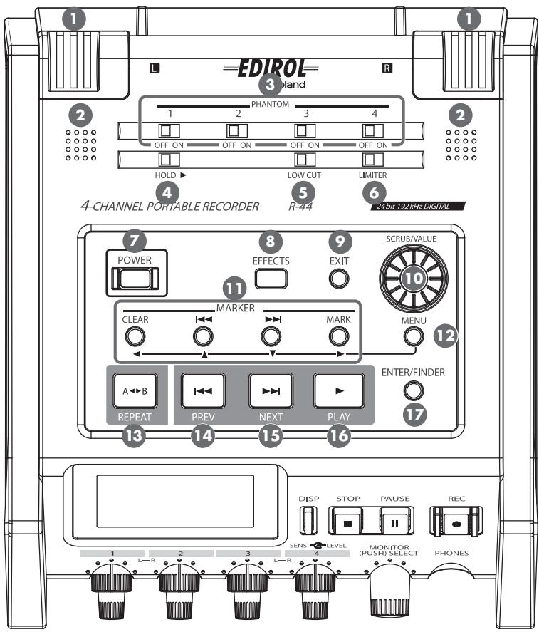
1 Internal Mics [MIC-L, MIC-R]
These stereo mics are built into the R-44. The audio entering MIC-L is recorded on the 1L channel, and the audio from MIC-R is recorded on the 1R channel. If you are recording with the internal mics, set the System Settings menu item Recording Setup to Int-Mic.
For details, refer to "Recording from the Internal Mics" (p. 32).
- Do not connect anything to input jacks that are not used.
Internal Speakers
These built-in speakers are for monitoring sound. If you want sound to be played from the internal speakers, set the System Settings menu item Speaker to ON. For details, refer to "Speaker Settings" (p. 44).
- No sounds are played from the internal speakers if headphones are connected to the Headphone jack 25. Sound is not played from the internal speakers while recording or in recording-standby mode to prevent acoustic feedback.
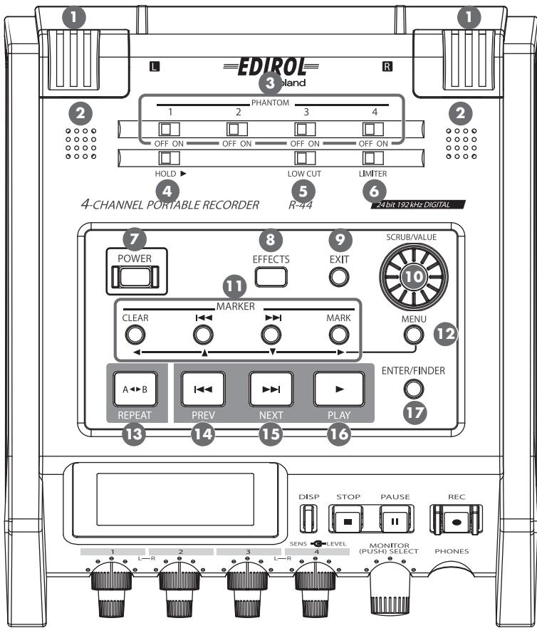
3 Phantom Power Switches [PHANTOM POWER]
These switches turn the phantom power on/off for the XLR connectors of the combo input jacks located on the right panel. You can turn phantom power on/off separately for channels 1/2/3/4 because they have separate switches.
- Always turn the phantom power off when connecting any device other than condenser microphones that require phantom power. You risk causing damage if you mistakenly supply phantom power to dynamic microphones, audio playback devices, or other devices that do not require such power. Be sure to check the specifications of any microphone you intend to use by referring to the manual that came with it.
![ROLAND R-44 - Phantom Power Switches [PHANTOM POWER] - 1](/content/2025/01/130964/images/34c54cde23c6e6dd7c8ac8e45cb5b78f2fb3b006bf9e803d7588eb9ba427798c.jpg)
Hold Switch [HOLD]
By selecting the HOLD ON position, you can disable the panel buttons so that unwanted operations will not occur if a button is pressed accidentally.
However, even if this switch is set to HOLD ON, the Phantom power switches 3, Low cut switch 5, Limiter switch 6, Input level knobs 23, and Monitor level knob 24 will still be operable.
Low Cut Switch [LOW CUT]
Turing this switch on allows you to record while cutting the lower range portion of the input signal. Turn it on when breath noise (breathing sounds during voice recording) or wind noise (when recording outside) may be a problem.
Limiter Switch [LIMITER]
This switch turns the input level limiter on/off.
The limiter compresses the input level appropriately to prevent distortion when the input level is too high. The limiter can be set to work with respect to each channel independently or for a combination of channels (linked). For details, refer to "Limiter link" (p. 68).
Power Switch [POWER]
This switch turns the power on/off. To turn the power on or off, press and hold the [POWER] switch for about two seconds. The [POWER] switch is lit blue when the power is on.
-
Do not turn off power to the R-44 in the following situations. The SD memory card may be damaged.
-
When writing to or reading from the SD memory card, such as during recording or playback If power is mistakenly turned off during recording, the recorded data may not be saved on the SD memory card.
Note that pressing the power switch during recording will not turn off power. - When "Now Processing!" or "Checking Card..." appears on the R-44's display
- When connected to a PC
Effects Button [EFFECTS]
This button puts the R-44 in Effect mode, where you can make effect settings. When effects are operating, the Effect button lights in orange.
For details, refer to "Setting the Color of Sound (Effects Settings)" (p. 55).
9 Exit Button [EXIT]
You use this button to return to the previous screen or to cancel an operation.
10 Scrub Dial [SCRUB/VALUE]
Use this dial to select a setting item or to change a value. You can also turn the scrub dial to move the current location forward or backward when the R-44 is stopped or when playback is paused.
In the finder screen, the scrub dial can also be used to select songs.
1 Marker Buttons [CLEAR] [←←] [▶→] [MARK] /
Cursor Buttons [▲] [▼] [▲] [▶]
When using as Marker buttons (p. 46)
Clear button [CLEAR]
This button deletes markers assigned with the [MARK] button. Markers are deleted successively, starting at the marker located immediately before the current location.
Marker button [i-4]
This button moves the position to the marker immediately before the current location (the previous marker).
If the current playback location is before the first marker, pressing this button moves the position to the beginning of the project. The position is also moved to the beginning of the project if no markers have been set.
Marker button [▶▶i]
This button moves the position to the marker immediately following the current location (the next marker).
If the current playback location is at the last marker, pressing this button moves the position to the end of the project. The position is also moved to the end of the project if no markers have been set.
Mark button [MARK]
You assign a marker to a desired location in the project file by pressing this button. Markers are numbered sequentially from the beginning of the project.
When using as Cursor button
You use these buttons to select items shown in the display.
12 MENU Button [MENU]
This button puts the R-44 in different modes where you can make various settings.
For details, refer to "System Setup" (p. 60).
13 A-B Repeat Button [A-B REPEAT]
This button lets you repeatedly play the region between two points (A and B) in the project. Simply assign marker A and marker B while the project is playing, and playback will repeat between markers A and B.
For details, refer to "Repeat Playback (A-B REPEAT)" (p. 47).
![ROLAND R-44 - A-B Repeat Button [A-B REPEAT] - 1](/content/2025/01/130964/images/53c676461282c2e304e0119459ffff9df1aa16165a0955e9eead2250b1001ef4.jpg)
PREV Button [PREV]
Pressing the [PREV] button while a project is playing or stopped returns the project to the beginning (00:00:00:00). Pressing this button at the beginning of a project moves to the previous project.
You can also press and hold down this button to rewind. This feature is available both while playing and while stopped.
- If Play Mode is set to Single in the Player Setup system setting, you cannot move to the previous or next project during playback.
NEXT Button [NEXT]
Pressing the [NEXT] button jumps to the next project. You can also press and hold this button to fast-forward. This feature is available both while playing and while stopped.
- If Play Mode is set to Single in the Player Setup system setting, you cannot move to the previous or next project during playback.
16 Play Button [PLAY]
This button starts playback. The [PLAY] button is lit blue during playback.
17 Enter/Finder Button [ENTER/FINDER]
You use this button to confirm a setting or to set a value. You can also press this button to use the Finder function. For more about the Finder function, refer to "Manipulating a Project (Finder)" (p. 48).
Front Panel
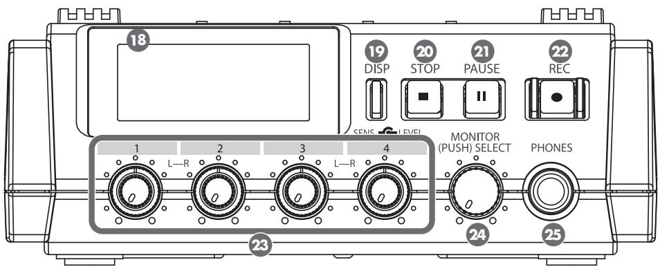
18 Display
The display shows information about the R-44's status.
For details, refer to "Display" (p. 18).
19 Display Button [DISP]
This button switches the contents of the R-44's display.
For details, refer to "Display" (p. 18).
20 Stop Button [STOP]
This button stops playback or recording. If you press the [STOP] button during playback, the timer counter displays the time when you pressed the [STOP] button.
21 Pause Button [PAUSE]
This button pauses playback or recording. During recording, sound is still output even if paused.
22 Record Button [REC]
Recording will begin immediately when you press the [REC] button. The [REC] button is lit red during recording. If you hold down the [PAUSE] button and press the [REC] button, the [REC] button will blink red, and the R-44 enters recording standby mode. Recording will begin when you press the [REC] button or [PAUSE] button 21.
23 Input Level Knobs 1-4 [LEVEL]/[SENS]
These knobs adjust the input level from each Combo input jack 1-4 (p.30).
You can adjust sensitivity to 11 levels: +4, -2, -8, -14, -20, -26, -32, -38, -44, -50, and -56 dBu. You can also set the level from negative infinity to +8 dB, with the central position at 0 dB.
- When using Internal mics ①, sensitivity can be set to one of three levels (Low, Mid, or Hi) and the level can be set from negative infinity to +18 dB. Also, sensitivity for both MIC-L and MIC-R can be adjusted with Input level knob 1. The level for MIC-L can be adjusted with Input level knob 1, and the level for MIC-R can be adjusted with Input level knob 2.
24 Monitor Level Knob [MONITOR (PUSH) SELECT]
This knob adjusts the output volume from the Internal speakers 2 and the Headphone jack 25.
This knob does not adjust the volume from the Line output jacks 33. If you want to adjust the volume of the Line output jacks, adjust the controls of the external speakers or playback system connected to the Line output jacks.
You can press the this knob from the main screen to select a channel to monitor.
For details, refer to "Display" (p. 18).
25 Headphone Jack [PHONES]
You can connect a set of headphones with this jack. Use the Monitor level knob 24 to adjust the volume.
If you connect headphones, no sound is output from the Internal speakers 2.
Side Panel (Left)
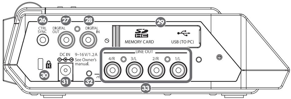
26 Control Sync Connector [CTRL SYNC]
You can perform clock-synchronized recording of up to 8 channels by connecting two R-44 units with a mini-type stereo cable via the CTRL SYNC connectors. You can also remotely link recording standby, start, and stop.
For details, refer to "Remotely Linking Two Connected R-44 Units" (p.73).
- Remote linking does not guarantee that two R-44 units will start recording at the same time. There will be a discrepancy of several milliseconds.
Digital Output Jack [DIGITAL OUT]
This connector outputs a digital signal. You can connect digital devices, such as speakers or mixers, with a coaxial type cable. This connector provides the same audio signal as the Headphone jack, but in digital form.
- The volume cannot be adjusted with the Monitor level knob 24.
28 Digital Input Jack [DIGITAL IN]
Connect an XLR type cable to this connector to record a digital signal. The digital input signal is recorded in stereo on channels 1L and 1R. If you want to record in monaural, you must change the Rec Mode setting in the System Settings menu. For details, refer to "1 Recording Setup" (p. 66).
Rubber Flap
Open this cover to expose the Memory card slot and USB connector.
Memory card slot [MEMORY CARD SLOT]
You can insert an SD memory card into this slot.
USB connector [USB]
You can connect the R-44 to your computer with the included USB cable and move or copy recorded projects. You can also move or copy files from your computer to the SD memory card.
For details, refer to "Connecting to a Computer" (p. 71).
30 Security Slot ( K )
You can attach a commercial available security cable to this slot to prevent theft.
http://www.kensington.com/
3 AC Adaptor Jack [DC IN]
You can connect either the included AC adaptor or a commercially available cable for an external power device.
For details, refer to "Connecting the AC Adaptor and Turning the Power On/Off" (p. 24).
![ROLAND R-44 - AC Adaptor Jack [DC IN] - 1](/content/2025/01/130964/images/754b7b16fd2064a0bf887ac930f45f712c39a1bc98b60470425a4a010bd7d39a.jpg)
Grounding Terminal
Depending on how the system is setup, you may experience discomfort or perceive that the surface feels brittle when you touch this device, microphones connected to it, or the metal portions of other objects, such as guitars. This sensation is caused by an infinitesimal electrical charge, which is absolutely harmless.
However, if you are concerned about this, connect the ground terminal to an external ground. When the unit is grounded, a slight hum may occur, depending on the setup. If you are unsure of how to connect a ground, contact the nearest Roland Service Center or an authorized Roland distributor, as listed on the "Information" page.
Do not connect to these objects
Water pipes (may result in shock or electrocution)
Gas pipes (may result in fire or explosion)
- Telephone-line ground or lightning rod (may be dangerous in the event of lightning)

Line Output Jacks [LINE OUT]
These jacks output an analog audio signal. You can use RCA cables to connect powered speakers, audio equipment, mixers, and other devices. The regulated output level is fixed at -20 dBu.
- The volume for each channel during playback can be adjusted on the Mixer screen (p. 19).
- Line output can be output as 4-indiv or monitor. Refer to “5 System Setup” in System settings (p. 69) for details.
Side Panel (Right)
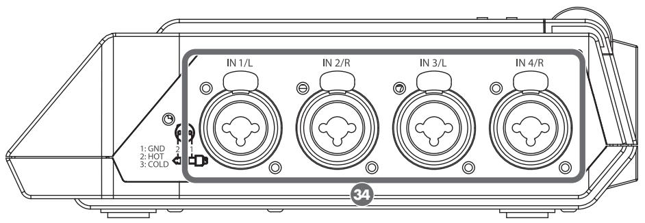
Combo Input Jacks 1-4
These analog audio input connectors are compatible with mic preamps. They support either XLR or phone plugs, which can be selected to match the connected device. They also accept either balanced or unbalanced connections.
You can use Combo input jacks 1-4 as four channels of monaural input or as two stereo pairs, 1/2 and 3/4. For details, refer to "1 Recording Setup" (p. 66).
- The XLR type supports 48 V phantom power and allows you to connect phantom-powered condenser microphones. In this case, turn on the Phantom power switch 3 on the top panel.
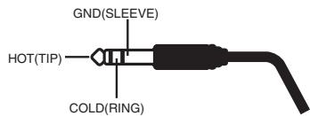
The R-44 is equipped with balanced (XLR/TRS) type connectors. The wiring diagrams for these connectors are shown at right. Connect them after first checking the wiring diagrams of the device you intend to connect.

1:GND 2:HOT 3:COLD
- If connection cables with resistors are used, the volume level of devices connected to the inputs (Combo input jacks 1-4) may be low. If this happens, use connection cables that do not contain resistors.
- To disconnect an XLR-type cable, push the metal latch while you unplug the connector.
Bottom Panel
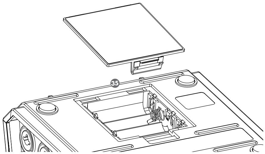

Battery Compartment
Install batteries here if you want to operate the R-44 on battery power.
The orientation of the batteries is shown inside the battery compartment.
Be sure to observe the correct polarity when installing the batteries.
If using the AC adaptor, you do not need to install batteries.
When the R-44 has sufficiently charged batteries, the power source automatically switches between battery and external power when the AC adaptor jack is connected or disconnected.
For details, refer to "Installing Batteries and Turning on the Power" (p. 25).
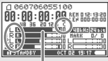
Display
While Playing or Stopped
The Main screen
The R-44's Main screen displays information about the project and the operational status of the R-44. You can press the [DISP] button to change the contents of the display.
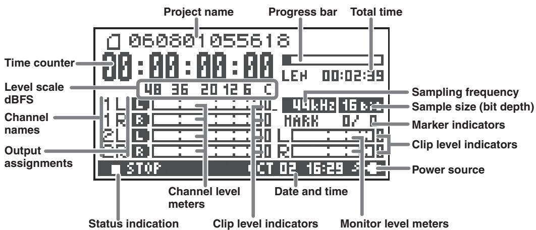
| Project name | Displays the name of the project. The file name is shown when you copy WAV files from your computer via USB to the R-44's SD memory card. File names containing double-byte characters (e.g., Japanese) are not displayed correctly, but such files can be played. |
| Time counter | Displays the time elapsed from the beginning of the project to the current position in hour:minute:second:1/100 second format. |
| Progress bar | Displays the current playback location relative to the entire project. |
| Total time (LEN: Length) | Displays the total time of the entire project. |
| Level scale dBFS | Displays the sound level for each channel (after adjusting input levels) in real time. The markings are relative to 0 dBFS (Full Scale) of the digital signal. For example, 12 indicates -12 dBFS. C is the clipping level (0 dBFS). |
| Clip level indicators | |
| Channel level meters | |
| Channel names | Displays up to four channel names. When using one stereo channel, 1L and 1R are shown. When using two stereo channels, 1L, 1R, 2L, and 2R are shown. For monaural projects, 1, 2, 3, and/or 4 is shown according to the number of channels. When the sensitivity setting is too high and clipping occurs the display is shown in inverted black and white. |
| Output assignments | Displays how the audio of each channel is assigned to the L/R output channels. L means that the audio is output to the left channel, R to the right channel, and R to both left and right channels. Channels that are not shown are not output. You can select a channel to be monitored by pressing the Monitor Level knob. You can also restore the default settings by pressing and holding down the Monitor Level knob for one second. The output is sent to the PHONES jack, Line output jacks, and digital output jack. * When Output Sel (p. 69) in the system settings is set to "monitor," the Line output jacks output sound as set in the output assignments. |
| Sampling frequency | Displays the sampling frequency and sample size (bit depth) of the currently selected project. |
| Sample size (bit depth) | |
| Marker indicator | The number on the left is the number of the marker located immediately before the current time counter value. The number on the right indicates the total number of markers assigned in the currently selected project. E indicates the end of the current project. |
| Monitor level meters | These are the output level meters. The output level assigned to the L/R channels of the monitor is displayed as the final output level after mixing the L and R channels separately. You can adjust the level of each channel with the channel level sliders from the Mixer screen. The level meter is calibrated at -36, -20, -12, -6, or -3 dBFS from the left. |
| Clip level indicators | |
| Power source | Displays the power supply source for the R-44. When power is supplied via the AC adaptor, a power plug icon is shown; when power is supplied via batteries or an external power supply device (p. 27), a battery icon is displayed. |
| Date and time | Displays the current date and time (p. 62, p. 70). |
If you press the [DISP] button from the Main screen, the progress bar area changes so the remaining project time (REM: REMAIN) is shown.
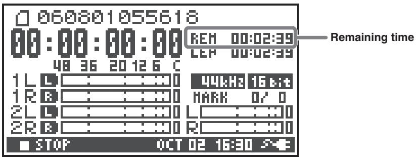
| Remaining time | Displays the remaining time during playback from the current location to the end of the project. |
The Mixer screen
From the Main screen, press the [DISP] button twice to show the Mixer screen. This screen lets you adjust the volume balance for monitoring.
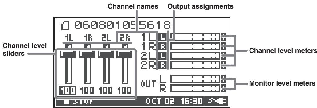
| Channel level sliders | These sliders adjust the playback level for each channel. Use the CURSOR buttons [▲] [►] to select a slider, and turn the [SCRUB/VALUE] dial to adjust the value. Each slider can be adjusted within the range 0–120. The default value is 100. * The settings are stored by the R-44 and not in the project. When you turn off the power, the settings revert to the default value. * These settings do not affect the recording levels. |
While Recording or in Recording Standby
The Main screen
The R-44's Main screen displays information about the project and the operational status of the R-44. You can press the [DISP] button to change the contents of the display.
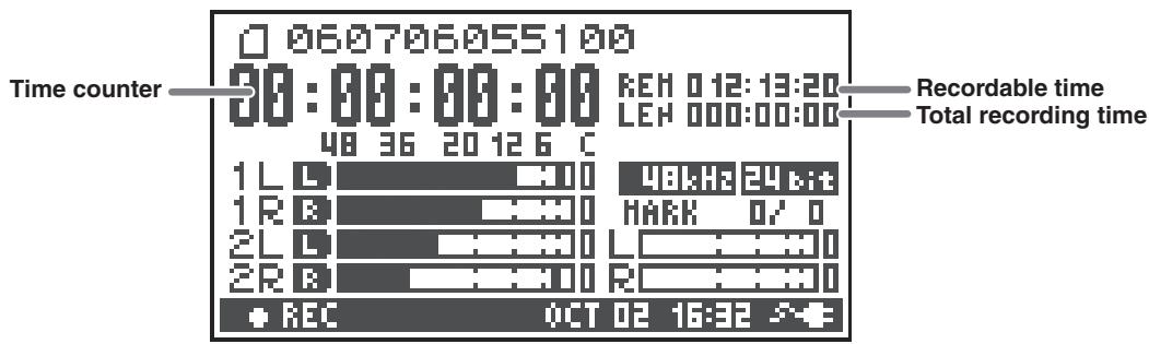
| Time counter | Displays the time elapsed from the beginning of the project to the current position in hour:min:sec:1/100 second format. |
| Recordable time | Displays the time that recording can take place. |
| Total recording time | Displays the total time from the beginning of recording to the current location. * Even if you record continuously, another new project will be created automatically when the project reaches 2 GB in size, and recording will continue. Even for recordings spanning multiple projects, the elapsed time since you first pressed the [REC] button is shown here. |
- For an explanation of the other displays, refer to "While Playing or Stopped" (p. 18).
If you press the [DISP] button from the Main screen, the recordable time display area shows the remaining space on the SD memory card.
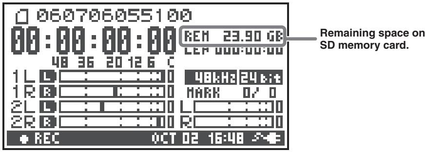
| Remaining space on SD memory card | Displays the amount of free space on the SD memory card. |
From the Main screen, press the [DISP] button twice to show the recording buffer capacity (BUF: buffer gauge).
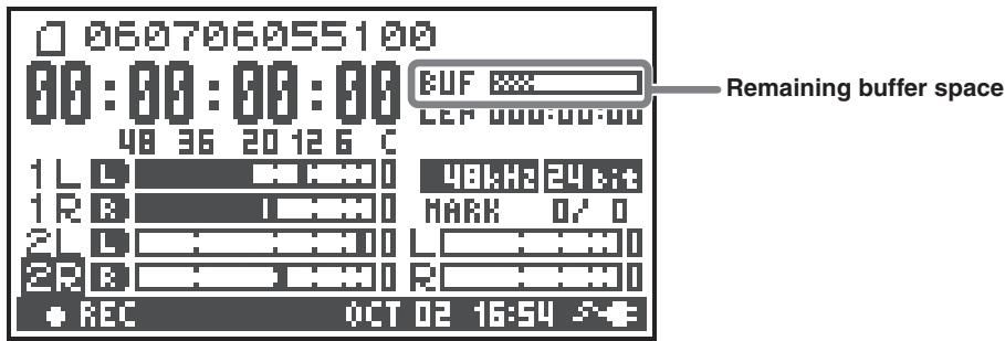
The recording buffer is memory that temporarily stores the input sound before it is written to the SD memory card. The buffer gauge indicates how much of the recording buffer has been used. Normally, the recording buffer never reaches capacity because input sound is immediately written to the SD memory card. However, if the SD memory card processing capability decreases and writing data to the SD memory card is delayed, then the data may accumulate to an excess and the buffer may overflow. (The SD memory card processing capability may be affected if file arrangement on the card becomes irregular due to project files being repeatedly written and deleted. If such a situation is encountered, you can restore the card to its original processing capability by formatting it.)
- When the recording buffer is close to capacity, the "SD buffering" message is displayed.
- When the recording buffer reaches capacity, the buffer gauge moves all the way to the right edge and the "SD Card Slow!" message is shown. Recording does not stop even if the "SD Slow" message is displayed, but some sound is not recorded. This message will not disappear until a button is pressed.
- For important recordings, we recommend formatting the SD memory card before use.
- Some SD memory cards may have a slow writing speed, so that even immediately after they have been formatted, recording at a high bit rate may cause a similar message to be displayed. When purchasing an SD memory card, please check whether it has been verified to work correctly with the R-44 (p. 76).
Projects
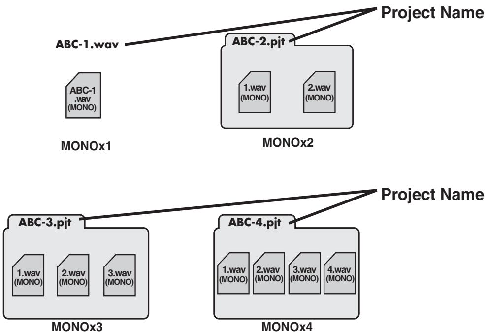
On the R-44, the data that you record and play back are handled in units called projects. On the SD memory card, each project actually consists of a folder with one or more files, as shown below.
If you connect the R-44 to your computer, you can see how these folders and files are organized. However, if you change, delete, or rename the files within a project, the R-44 may be unable to play that project. Please use caution.
In the system settings, the Recording Setup parameter Rec Mode (p. 67) lets you specify the type of project you want to record.
Monaural projects
| Type | Structure |
| MONOx1 | If there is only one channel, a monaural WAV file will be created with a name consisting of the project name and a .wav extension. |
| MONOx2 | If there are 2–4 channels, a folder will be created with a name consisting of the project name plus an extension of .pjt. In that folder, monaural WAV files will be created with names consisting of the channel number and a .wav extension. |
| MONOx3 | |
| MONOx4 |
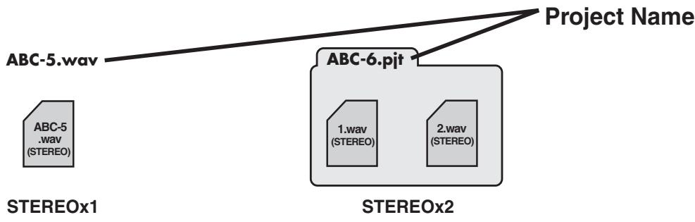
Stereo projects
| Type | Structure |
| STEREOx1 | If there is only one stereo channel pair, a stereo WAV file will be created with a name consisting of the project name and a .wav extension. |
| STEREOx2 | If there are two stereo channel pairs, a folder will be created with a name consisting of the project name plus an extension of .pjt. In that folder, stereo WAV files will be created with names consisting of the channel number and a .wav extension. |
Four-channel projects
| Type | Structure |
| 4CH | A four-channel WAV file will be created with a name consisting of the project name and a .wav extension. |
ABC-7.wav——Project Name
- If you want to load these files onto your computer, make sure that your waveform editing software supports four-channel files.

4CH
Limitations on file size
The R-44 can handle files up to 2 GB in size. If the file size reaches 2 GB during recording, the file is closed. Then, a new file is created and recording continues. When you finish recording, these files appear as separate projects.
About BWF
In "5 System Setup" (p. 69), under system settings, you can set Project File to BWF so that the files created during recording and editing will be BWF files. BWF (Broadcast Wave Format) files contain information about the recording time and recording device (EDIROL R-44) in addition to the data of a conventional WAV file. The file can be used by waveform editing software that supports BWF.
Caution when copying files from your computer
Be aware of the following when copying files from your computer to the R-44's SD memory card.
- The R-44 can play only linear PCM WAV files at sampling frequencies of 44.1, 48, 88.2, 96, or 192kHz and bit depths of 16 or 24 bits. It cannot play any other type of file.
- File and folder names containing double-byte characters (e.g., Japanese) are not displayed correctly.
- Any files other than WAV files cannot be recognized by the R-44 and will not be displayed.
- Files beginning with ". ." (dot) will not be displayed.
- You must not copy files larger than 2 GB into the R-44's SD memory card. Doing so will make the R-44's operation unstable, and in the worst case might even damage the files in the SD memory card.
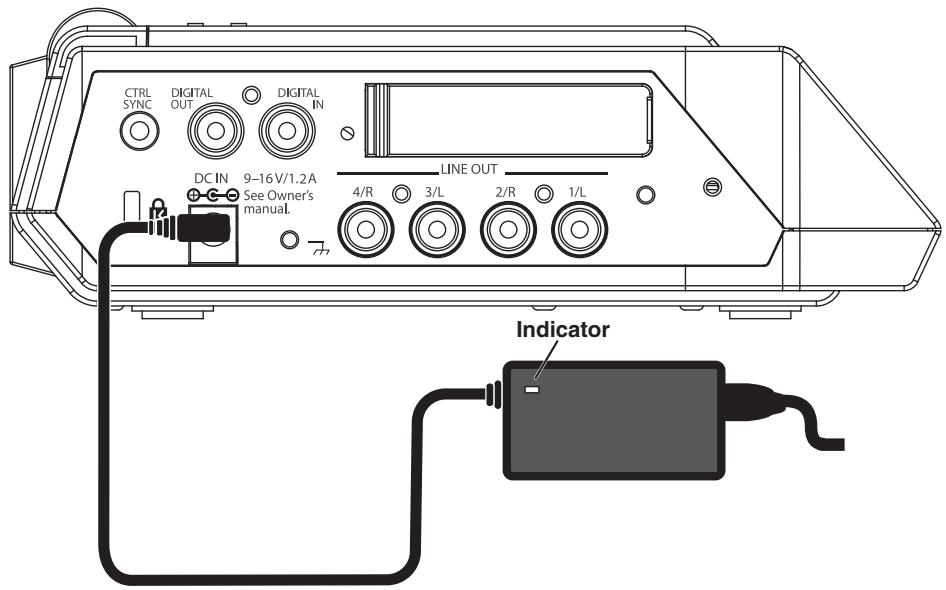
Connecting the AC Adaptor and Turning the Power On/Off
- Once the connections have been completed, turn on power to your various devices in the order specified. By turning on devices in the wrong order, you risk causing malfunction and/or damage to speakers and other devices.
- Reduce the volume before turning on power. Even when the volume is turned down, sound may be produced when turning on the power. This is not a defect.
- If you connect the AC adaptor when batteries are installed, the power will be supplied from the AC adaptor.
- Place the AC adaptor so the side with the indicator (refer to illustration) faces upwards and the side with textual information faces downwards. The indicator will light when you plug the AC adaptor into an AC outlet.
Turning on the power
1 Insert the AC adaptor into the AC adaptor jack on the R-44's side panel (left).
- Use only the included AC adaptor.
2 Plug the AC adaptor into an AC power outlet.
3 To turn the power on, press and hold the [POWER] switch for about two seconds.
Wait until the Main screen appears.
- Due to a circuitry protection feature, this unit requires a few moments after power-up before it is ready for normal operation.
Turning off the power
1 Confirm that recording/playback has been stopped.
2 While the Main screen is displayed, press and hold the [POWER] switch for about 2 seconds to turn the power off.
- If there are batteries in the unit while an AC adaptor is being used, normal operation will continue should the line voltage be interrupted (power blackout or power cord disconnection).
Installing Batteries and Turning on the Power
Types of batteries that can be used
AA alkaline batteries (LR6) and AA nickel metal-hydride (HR15/51) only
The R-44 cannot recharge nickel metal-hydride batteries. You must use a separate charger.
You must specify the type of batteries in the R-44's System Settings menu item "5 System Setup" (p. 69). The R-44 will not operate correctly if the specified battery type does not match the actual batteries.
1
Make sure that the R-44 is turned off, and disconnect the AC adaptor from the AC adaptor jack on the R-44's side panel (left).
2
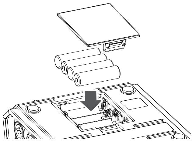
Detach the battery cover from the bottom panel of the R-44.
- When turning the unit upside-down, handle with care to avoid dropping it, or allowing it to fall or tip over.
- When turning the unit upside-down, place newspapers or magazines under the four corners or at both ends to prevent damage to the buttons and controls. Also, you should try to orient the unit so no buttons or controls get damaged.
3
Insert four AA batteries into the battery compartment, making sure to observe the correct polarity (+ and - symbols).
4
Replace the battery cover.
5
Turn on the R-44.
6
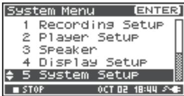
Press the [MENU] button.
7
Use the Cursor buttons [▲] [▼] to select 5 System Setup.
8
Press the [ENTER] button.
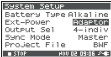
9
Using the [SCRUB/VALUE] dial, set the Battery Type to Alkaline if installing alkaline batteries or to Ni-MH if installing nickel metal-hydride batteries. The setting is activated as soon as you select it.
10
When finished with the setting, press the [EXIT] button to return to the previous screen.
11
When you have returned to the System Menu screen, press the [EXIT] button once again. The [ENTER] button will be blinking on the display. Press the [EXIT] button to return to the Main screen if you do not need to make additional settings.
Caution when using battery power on the R-44
- If you operate on battery power for an extended time, the batteries will become hot. Be careful not to burn yourself.
- Do not mix new batteries with used batteries or mix batteries of differing types.
- If you will not be using the R-44 for an extended time, we recommend that you remove the batteries to prevent leakage or other accidents.
- When using a USB cable to connect the R-44 to your computer, use the AC adaptor to prevent the loss of power while the connection is active.
Battery Status
When using the R-44 on battery power, a battery icon is shown in the lower right of the display. As battery capacity decreases, the battery icon changes as follows.
| Remaining charge | Display |
| Level 4 (sufficient) | 060706055100 88:88:88:88 48 36 20 12 6 C 1 3 4 8 STOP OCT 02 19 |
| Level 3 | 060706055100 88:88:88:88 48 36 20 12 6 C 1 3 4 8 STOP OCT 02 19 |
| Level 2 | 060706055100 88:88:88:88 48 36 20 12 6 C 1 3 4 8 STOP OCT 02 19 |
| Level 1 | 060706055100 88:88:88:88 48 36 20 12 6 C 1 3 4 8 STOP OCT 02 19 |
| Level 0 (little remaining) | 060706055100 88:88:88:88 48 36 20 12 6 C 1 3 4 8 STOP OCT 02 19 |
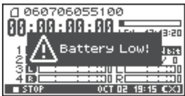
When the battery reaches Level 0, the message in the figure is shown. Replace the batteries as soon as possible.
If you continue using the R-44 when the batteries are low, the screen is the figure is shown, and then the power automatically turns off shortly thereafter.
Battery life
(When using alkaline batteries, 44.1 kHz, 16-bit, stereo, with phantom power off)
| Continuous playback | approximately 4 hours |
| Continuous recording | approximately 4 hours |
- The values for battery life shown above are only approximate; they will vary depending on your system and conditions of use.
- Battery life is shorter when the following settings are used. Illumination is on, button lights are bright, display is bright, phantom power is on, sampling frequency is high, 4-channel recording is used, or the internal speakers are used.
Using External Power Sources
When using an external power supply, be sure to set the final voltage.
The final voltage refers to the voltage when voltage can no longer be supplied because the capacity of the external power source is reduced and voltage decreases as electricity is consumed. If the final voltage is not properly set for the external power source, the remaining power display cannot be shown. Refer to the user's manual of the external power supply for the final voltage value.
Furthermore, when the "Battery Low" message is displayed, the recording automatically stops, and the power automatically turns off. Turn the R-44's power off and change the external power source.
- When using an external power source, even when power is automatically cut off, the R-44 starts within 30 seconds after power is turned back on. During this period, the final voltage settings can be changed.
- Read the following to set the final voltage for the R-44.

Refer to the user's manual for the external power source when using an external power source.
Setting the final voltage

Press the [MENU] button.
The display shows the System menu.
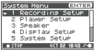

Use the Cursor buttons [▲] [▼] to select 5 System Set Up, and press the [ENTER] button.
The System Setup screen is shown.

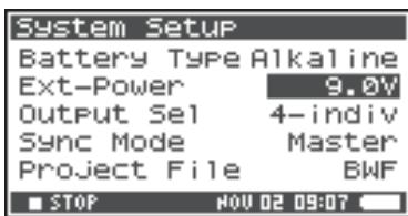
Use the Cursor buttons [▲] [▼] to select the Ext-Power item.

Use the [SCRUB/VALUE] dial to set the final voltage.
Final voltage values:
Adaptor/9.0/9.5/10.0/10.5/11.0/11.5/12.0 V
- The final voltage value will differ according to the external power source specifications. Check the specifications for the external power source being used for details.
- When the AC adaptor is used for power, set the final voltage (Ext-Power) to Adaptor.

Press the [EXIT] button twice to return to the Main screen.
This completes setting the final voltage.
Preparing the SD Memory Card
The R-44 uses an SD memory card.
The SD memory card is sold separately. Visit the Roland website (http://www.roland.com) before making
a purchase. The website provides the most recent information regarding compatibility.
Inserting the SD Memory Card
1 Confirm that the power is turned off.
If the power is on, turn it off. Press and hold the [POWER] switch on the R-44 to turn power on or off.
2 Open the Rubber flap on the side of the unit.
3 Insert the memory card.
- When inserting the SD memory card, make sure the front of the card is facing up and insert the card slowly. If the card is forcibly inserted incorrectly, the R-44 or the SD memory card may be damaged. Please exercise caution.
- Carefully insert the memory card all the way in until it is firmly in place.
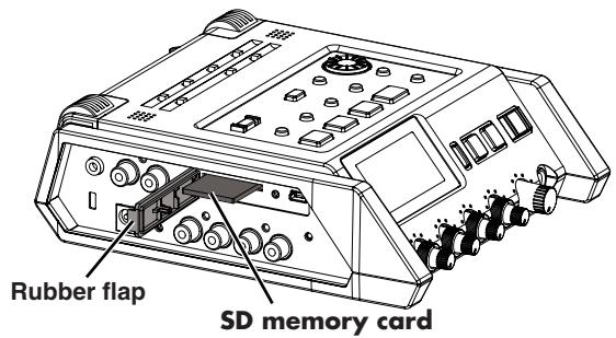
4 Close the Rubber flap.
5 Turn power on.
Press and hold down the [POWER] switch to turn on the power.
When using an SD memory card with the R-44 for the first time
When using an SD memory card with the R-44 for the first time, the memory card must be formatted.
Please format the memory card following the procedure in " Formatting and Checking the SD Memory
Card" (p. 64). "SD Unformatted" is shown when an unformatted memory card is inserted into the R-44.
The SD memory card write protect feature (LOCK)
The contents of the memory card can be protected by sliding the write protect switch on the side of the memory card to the "LOCK" position. Unlock the write protect switch to delete data on the card.
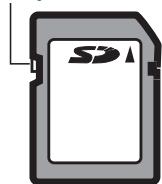
Write protect switch
Removing the SD Memory Card
1 Turn off power to the R-44.
2 Open the Rubber flap.
3 Lightly push the memory card inward, then release it.
Remove the memory card after it pops out toward you.
- Never insert or remove a memory card while this unit's power is on. Doing so may corrupt the data on the memory card.
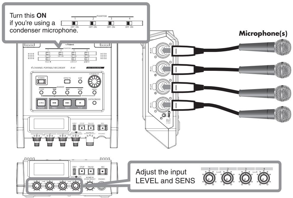
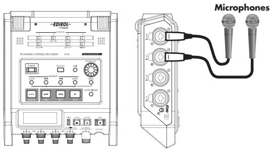
Recording from a Connected Microphone
The following describes how to record audio from a maximum of four microphones connected to the R-44's Combo input jacks.
- Connections
Connect the microphone(s) to the Combo input jack(s).
Acoustic feedback could be produced depending on the location of microphones relative to speakers. This can be remedied by:
- Changing the orientation of the microphone(s).
- Relocating microphone(s) at a greater distance from speakers.
- Lowering volume levels.
- Phantom power switch
Turn this ON when connecting a phantom-powered condenser microphones.
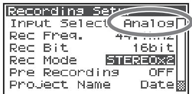
- System settings
- Press the [MENU] button.
- In 1 Recording Setup, set Input Select to Analog. Set the other items in 1 Recording Setup as appropriate for the recording you want to make.
- When finished with the settings, press the [EXIT] button twice to return to the Main screen.
- For more about system settings, refer to "System Setup" (p. 60).
- Limiter
Turn this ON if you want to prevent unexpectedly loud sounds or strong attacks from producing clipping noise.
The limiter threshold is -10 dB relative to digital full scale.
The limiter can group and link each channel. Refer to Limiter link (p. 68).
Low cut
You can turn low cut ON when breathing noise (the sound of breathing while recording a voice) or wind noise (when recording outside) may be a problem.
The low cut feature records while cutting the lower range of the input signal.
- Input level knobs
These knobs adjust sensitivity/input levels.
When recording in STEREOx2, these knobs control the following signals.
| Channel 1 | STEREO 1 L-channel | SENS/INPUT LEVEL 1 knob |
| Channel 2 | STEREO 1 R-channel | SENS/INPUT LEVEL 2 knob |
| Channel 3 | STEREO 2 L-channel | SENS/INPUT LEVEL 3 knob |
| Channel 4 | STEREO 2 R-channel | SENS/INPUT LEVEL 4 knob |
Adjusting the input levels
- Turn the Input level knob [SENS] (outer) all the way left.
- Turn the Input level knob [LEVEL] (inner) to the center position. This position is 0dB .
- Hold down the [PAUSE] button and press the [REC] button.
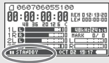
The R-44 enters recording standby mode. During recording standby, the [REC] button blinks and the indication alternates between REC and STANDBY.
- Play the sound to be recorded into the microphone.
Gradually turn the Input level knob [SENS] toward the right.
Sensitivity has 11 steps of +4, -2, -8, -14, -20, -26, -32, -38, -44, -50, and -56 dBu.
-
When the channel name display reverses, the input level has reached the clipping level. Set the knob to the position just before the display reverses.
-
Adjust the Input level knob [LEVEL] so that the Level meter shown in the display reaches a point slightly before C (clip level). If the recording level is too low, quiet sounds will not be recorded. If the recording level is too high, loud sounds will be distorted, producing a crackling noise in the recording.
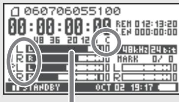
level meter (dBFS)
- When the channel name is blinking, clipping has occurred at the sensitivity adjustment stage. In this case, clipping occurs even if the Level meter does not reach the clip level.
- The Level meter displays the clip level (C) in values relative to 0 dBFS (FS = full scale). For example, 12 indicates -12 dBFS.
Difference between sensitivity and input level
Sensitivity and input level are differentiated in their use, as shown below.
| Sensitivity | Adjusts to an appropriate volume according to the input signal strength. |
| Input Level | Adjusts the volume balance between the channels. Also, performs minute adjustments when adjusting cannot be done with sensitivity. |
Noise can be controlled by adjusting sensitivity to the largest value without distortion.
- Record button [REC]
If you want to begin recording immediately, press the [REC] button.
Recording standby
If you want to put the R-44 in recording standby mode to be ready to record, hold down the [PAUSE] button and press the [REC] button.
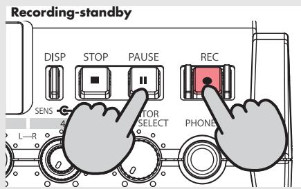
During recording standby, the [REC] button blinks and the indication alternates between REC and STANDBY.
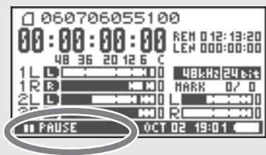
When recording is paused, the [REC] button blinks. In addition, the indication alternates between REC and PAUSE.
Press the [REC] or [PAUSE] button during recording standby or while paused to start recording.
You can adjust input levels during recording standby.
Other settings
If you want to monitor the sound being recorded, connect headphones to the PHONES jack and use the Monitor level knob to adjust the volume.
Adjusting the Monitor level knob does not affect the level of the sound actually being recorded.
To play the recorded sound, refer to "Playing Back" (p. 41).
Recording from the Internal Mics
The following describes how to record an audio source via the R-44's internal microphones.
- Phantom power switch
Turn this OFF.
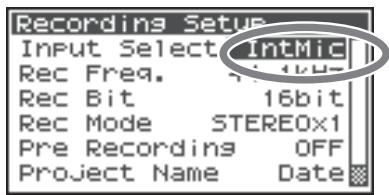
- System settings
- Press the [MENU] button.
-
In 1 Recording Setup, set Input Select to IntMic. Set the other items in 1 Recording Setup as appropriate for the recording you want to make.
-
When finished with the settings, press the [EXIT] button twice to return to the Main screen.
-
For more about system settings, refer to "System Setup" (p. 60).
- The limiter settings are invalid.
- Input level knobs
These knobs adjust the sensitivity and input levels.
Adjusting the input levels
- Turn the Input level knob [SENS] (outer) all the way left.
- Turn the Input level knobs [LEVEL] (inner) to the center position. This position is 0 dB.
- Hold down the [PAUSE] button and press the [REC] button. The R-44 enters recording standby mode. During recording standby, the [REC] button blinks and the indication alternates between REC and STANDBY.
-
Play the sound to be recorded into the microphone. Gradually turn the Input level knob [SENS] 1 toward the right. Sensitivity has 3 steps: Lo, Mid, and Hi.
-
Sensitivity can be changed simultaneously for both MIC-L and -R with Input Level knob 1.
-
When the channel name display reverses, the input level has reached the clipping level. Set the knob to the position just before the display reverses.
-
Gradually turn the Input level knob [LEVEL] toward the right.
-
Input levels of the internal mics are adjusted by Input level knob 1 (MIC-L) and knob 2 (MIC-R).
-
Adjust the level so that the level meter shown in the display reaches a point slightly before C (clip level). If the recording level is too low, quiet sounds will not be recorded. If the recording level is too high, loud sounds will be distorted, producing a crackling noise in the recording.
level meter (dBFS)
- When the channel name is blinking, clipping has occurred at the sensitivity adjustment stage. In this case, clipping occurs even if the level meter does not reach the clip level.
- The level meter displays the clip level (C) in values relative to 0 dBFS (FS = full scale). For example, 12 indicates -12 dBFS.
- Record button [REC]
Press the [REC] button to begin recording.
For details on recording standby, refer to "Recording standby" (p. 31).
Other settings
If you want to monitor the sound being recorded, connect headphones to the PHONES jack and use the Monitor level knob to adjust the volume.
Adjusting the Monitor level knob does not affect the level of the sound actually being recorded.
To play the recorded sound, refer to "Playing Back" (p. 41).
Recording Digital Audio from a Digital Device
The following describes how to record from a digital device connected to the R-44's Digital input jack.
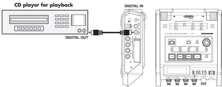
- Connections
Connect your digital device to the Digital input jack. You will need a separately available coaxial cable to connect your device to the R-44's Digital input jack.
- Phantom power switch
Turn this OFF.
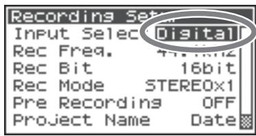
- System settings
- Press the [MENU] button.
- In 1 Recording Setup, set Input Select to Digital.
- Set the sampling frequency to match the input source.
- Set the other items in 1 Recording Setup as appropriate for the recording you want to make.
- When finished with the settings, press the [EXIT] button twice to return to the Main screen.
- For more about system settings, refer to "System Setup" (p. 60).
- Please set the sampling frequency to match the device being input.
- The R-44 is able to synchronize to the clock signal of the Digital input jack.
- When the input sampling frequency and set sample size differ, the sampling frequency display blinks and mute data is generated.
- When Sync Mode is set to Slave, digital input is disabled. Set Sync Mode to Master when recording from a digital device. Refer to "5 System Setup" (p. 69) in "System Setup" for settings.
- Record button [REC]
Press the [REC] button to begin recording.
For details on recording standby, refer to "Recording standby" (p. 31).
Other settings
If you want to monitor the sound being recorded, connect headphones to the PHONES jack and use the Monitor level knob to adjust the volume.
Adjusting the Monitor level knob does not affect the level of the sound actually being recorded.
To play the recorded sound, refer to "Playing Back" (p. 41).
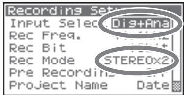
Simultaneously Recording Sound from Connected Microphones and a Digital Device
The following describes how to record sound from microphones connected to the R-44's Combo input jacks 3 and 4 and a digital device connected to the Digital input jack.
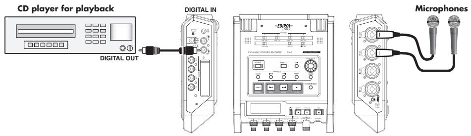
- Connections
Connect your microphones to Combo input jacks 3 and 4. Connect your digital device to the Digital input jack.
You will need a separately available coaxial cable to connect your device to the R-44's Digital input jack.
- Phantom power switch
Turn this ON when connecting a phantom-powered condenser microphones.
- System settings
- Press the [MENU] button.
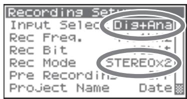
- In 1 Recording Setup, set Input Select to Dig+Ana.
- Set the Rec Mode to STEREOx2. Set the other items in 1 Recording Setup as appropriate for the recording you want to make.
-
When finished with the settings, press the [EXIT] button twice to return to the Main screen.
-
If Rec Freq is set to 192 kHz after setting Dig+Ana, Input Select is automatically changed to Digital and Rec Mode is changed to STEREOx1.
-
Please set the sampling frequency to match the device being input.
- For more about system settings, refer to "System Setup" (p. 60).
- Limiter
Turn this OFF when recording an audio source whose levels have already been adjusted (in contrast to a live audio source whose levels might change unpredictably), or if you have already checked the maximum volume levels that are going to occur.
Turn this ON if you need to prevent clipping (distortion) caused by unexpected loud volumes or strong attacks.
Low cut
You can turn low cut on when breathing noise (the sound of breathing while recording a voice) or wind noise (when recording outside) may be a problem.
The low cut feature records while cutting the lower range of the input signal.
- The Limiter, Low cut and Input level knob [SENS] settings are invalid for digital input.
- Input level knobs
These knobs adjust the input levels.
Use the following when simultaneously recording sound from microphones and a digital device.
| Channel 1 | Digital input L channel | The input level and sensitivity cannot be adjusted with the input level knob. |
| Channel 2 | Digital input R channel | |
| Channel 3 | Analog input L channel | Input level, SENS knob 3 |
| Channel 4 | Analog input R channel | Input level, SENS knob 4 |
Refer to "Adjusting the input levels" (p. 30).
- Record button [REC]
Press the [REC] button to begin recording.
For details on recording standby, refer to "Recording standby" (p. 31).
Other settings
If you want to monitor the sound being recorded, connect headphones to the PHONES jack and use the Monitor level knob to adjust the volume.
Adjusting the Monitor level knob does not affect the level of the sound actually being recorded.
To play the recorded sound, refer to "Playing Back" (p. 41).
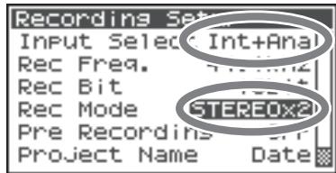
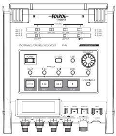
Simultaneously Recording Sound from Connected External Microphones and the Internal Mics
The following describes how to record sound from the microphones connected to the R-44's Combo input jacks 3 and 4 and the internal mics.
Connections
Connect your microphones to Combo input jacks 3 and 4.
- Phantom power switch
Turn this ON when connecting phantom-powered condenser microphones.
- System settings
- Press the [MENU] button.
- In 1 Recording Setup, set Input Select to Int+Ana.
- Set the Rec Mode to STEREOx2.
Set the other items in 1 Recording Setup as appropriate for the recording you want to make.
-
When finished with the settings, press the [EXIT] button twice to return to the Main screen.
-
If Rec Freq is set to 192 kHz after setting Int+Ana, Input Select is automatically changed to Digital and Rec Mode is changed to STEREOx1.
- For more about system settings, refer to "System Setup" (p. 60).
- Limiter
Turn this OFF when recording an audio source whose levels have already been adjusted (in contrast to a live audio source whose levels might change unpredictably), or if you have already checked the maximum volume levels that are going to occur.
Turn this ON if you need to prevent clipping (distortion) caused by unexpected loud volumes or strong attacks.
Low cut
You can turn low cut on when breathing noise (the sound of breathing while recording a voice) or wind noise (when recording outside) may be a problem.
The low cut feature records while cutting the lower range of the input signal.
- Input level knobs
These knobs adjust input levels.
Use the following when simultaneously recording sound from internal and external microphones.
| Channel 1 | Internal mic L channel | Input level, SENS knob 1 |
| Channel 2 | Internal mic R channel | |
| Channel 3 | Analog input L channel | Input level, SENS knob 3 |
| Channel 4 | Analog input R channel | Input level, SENS knob 4 |
Refer to Adjusting the input levels (p. 30).
Record button [REC]
Press the [REC] button to begin recording.
For details on recording standby, refer to "Recording standby" (p. 31).
Other settings
If you want to monitor the sound being recorded, connect headphones to the PHONES jack and use the Monitor level knob to adjust the volume.
Adjusting the Monitor level knob does not affect the level of the sound actually being recorded.
To play the recorded sound, refer to "Playing Back" (p. 41).
Recording Digital Audio from an Analog Device
The following describes how to record from an analog device connected to the R-44's Combo input jacks.
Connections
Connect your analog device to the Combo input jacks. You will need a separately available audio cable to connect your device to the R-44's Combo input jacks.
- Phantom power switch
Turn this OFF.
- System settings
- Press the [MENU] button.
- In 1 Recording Setup, set Input Select to Analog. Set the other items in 1 Recording Setup as appropriate for the recording you want to make.
- When finished with the settings, press the [EXIT] button twice to return to the Main screen.
- For more about system settings, refer to "System Setup" (p. 60).
- Limiter
Turn this ON if you want to prevent unexpectedly loud sounds or strong attacks from producing clipping noise.
The limiter threshold is -10 dB relative to digital full scale.
The limiter can group and link each channel. Refer to "Llimiter link" (p. 68).
- Input level knobs
Adjust the Input level 1 (L) and 2 (R) knobs. If there are channels to which you have not connected anything, turn their Input level knobs to the minimum position.
Refer to "Adjusting the input levels" (p. 30).
- Record button [REC]
Press the [REC] button to begin recording.
For details on recording standby, refer to "Recording standby" (p. 31).
Other settings
If you want to monitor the sound being recorded, connect headphones to the PHONES jack and use the Monitor level knob to adjust the volume.
Adjusting the Monitor level knob does not affect the level of the sound actually being recorded.
To play the recorded sound, refer to "Playing Back" (p. 41).
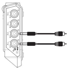
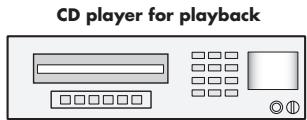
Simultaneously Recording Sound from Connected Microphones and an Analog Device
The following describes how to record sound from microphones connected to the R-44's Combo input jacks 3 and 4 and an analog device connected to Combo input jacks 1 and 2.
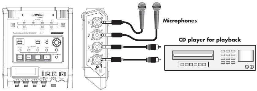
Connections
Connect your microphones to Combo input jacks 3 and 4. Connect your analog device to the Combo input jacks 1 and 2.
You will need a separately available coaxial cable to connect your device to the R-44's Combo input jacks.
- Phantom power switch
Turn this ON when connecting a phantom-powered condenser microphones.
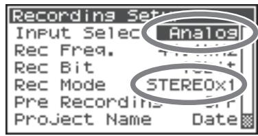
- System settings
- Press the [MENU] button.
- In 1 Recording Setup, set Input Select to Analog.
- Set the Rec Mode to STEREOx2.
Set the other items in 1 Recording Setup as appropriate for the recording you want to make.
-
When finished with the settings, press the [EXIT] button to return to the Main screen.
-
For more about system settings, refer to "System Setup" (p. 60).
- If Rec Freq is set to 192 kHz after setting Rec Mode to STEREOx2, Input Select is automatically changed to Digital and Rec Mode is changed to STEREOx1.
- Limiter
Turn this ON if you want to prevent unexpectedly loud sounds or strong attacks from producing clipping noise. The limiter threshold is -10 dB relative to digital full scale. The limiter can group and link each channel. Refer to "Limiter link" (p. 68).
Low cut
You can turn low cut on when breathing noise (the sound of breathing while recording a voice) or wind noise (when recording outside) may be a problem.
The low cut feature records while cutting the lower range of the input signal.
- Input level knobs
These knobs adjust input levels.
Use the following when simultaneously recording sound from microphones and an analog device.
| Channel 1 | Analog input L channel | Input level, SENS knob 1 |
| Channel 2 | Analog input R channel | Input level, SENS knob 2 |
| Channel 3 | Analog input L channel | Input level, SENS knob 3 |
| Channel 4 | Analog input R channel | Input level, SENS knob 4 |
Refer to "Adjusting the input levels" (p. 30).
Record button [REC]
Press the [REC] button to begin recording.
For details on recording standby, refer to "Recording standby" (p. 31).
Other settings
If you want to monitor the sound being recorded, connect headphones to the PHONES jack and use the Monitor level knob to adjust the volume.
Adjusting the Monitor level knob does not affect the level of the sound actually being recorded.
To play the recorded sound, refer to "Playing Back" (p. 41).
This section explains how to play audio recorded on the R-44 and projects on the R-44 SD memory Card. Make the correct settings and connections before playing anything back.
- Connections Before Playback. (p. 41)
- Setup Before Playback. (p. 43)
- Playing Back. (p. 45)
Connections Before Playback
To prevent malfunction and/or damage to speakers or other devices, always turn down the volume, and turn off the power on all devices before making any connections.
Connecting Headphones
Headphones provide a convenient way to monitor while recording or to check sound immediately after recording.
- Turn the Monitor level knob all the way to the left to minimize the volume.
- Connect your headphones to the PHONES jack.
- Slowly turn the Monitor level knob toward the right to adjust the volume.
Connecting Amplified Speakers
The following describes how to connect amplified speakers that have line input jacks or a digital input jack.
- Turn off the power to the R-44.
- Minimize the volume of the speakers you want to connect, and then turn off the power.
- Depending on the type of speakers you are using, connect the amplified speakers to the [LINE OUT] jacks or [DIGITAL OUT] jack.
- Turn on the R-44's power.
- Turn on your speakers, and gradually increase the volume to the desired level.
Connecting a Mixer or Other Analog Device
The following describes how to connect a mixer or other audio device that has line input jacks to the output jacks of the R-44.
-
Connect the mixer to the [LINE OUT] jacks. You will need separately available audio cables (not included) to connect to the [LINE OUT] jacks.
-
Turn off the power to the R-44.
-
Minimize the volume of the mixer or other device being connected.
-
Line output can be output as 4-indiv or monitor. Refer to "System Setting" in "5 System Setup" (p. 69) for details.
-
Turn on the R-44's power.
- Turn on your mixer, and gradually increase the volume to the desired level.
Connecting a Device Having a Digital Input Port
The following describes how to connect devices with digital input ports, such as mixers, speakers, or recording devices, to the [DIGITAL OUT] jack of R-44.
The sampling frequency of the project playing back will be the sampling frequency of the audio output from the digital output connector.
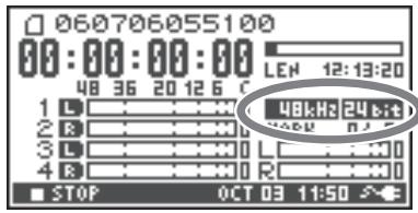
- Turn off the power to the R-44.
- Turn off power to the device with the digital input port.
-
Connect the [DIGITAL OUT] jack to the digital input connector of the device with digital input.
-
You will need a separately available coaxial cable (not included) to connect your digital device to the [DIGITAL OUT] jack.
-
Turn on the R-44's power.
-
Turn on power to the device with the digital input port.
-
You cannot adjust the volume of the digital signal on the R-44.
Setup Before Playback
Player Setup
1 Press the [MENU] button.
The System Menu screen appears on the display.

2 Use the Cursor buttons [▲][▼] to choose 2 Player Setup, and press the [ENTER] button.
The Player Setup screen appears.
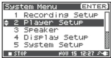
3 Use the [SCRUB/VALUE] dial to choose the Play Mode value.
- The setting is applied as soon as you select it. You do not need to press the [ENTER] button.
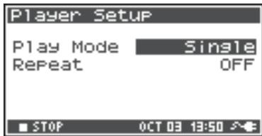
You can also setup the following items.
| Menu | Player Setup settings | Playback method |
| Play Mode | Single | Selects the play mode. Only the selected project will play. |
| Sequential | The projects in the folder containing the currently selected project will play consecutively. | |
| Repeat | OFF, ON | Selects whether playback will repeat. If Play Mode is Single, only that project will be repeated. If it is Sequential, the projects in the folder containing the currently selected project play consecutively, and then the projects in the same folder will be repeated consecutively from the beginning. |
-
The values in boldface are the default values.
-
For more about system settings, refer to "System Setup" (p. 60).
Speaker Settings
You can use the R-44's Internal speakers to monitor the sound without having to connect headphones or other equipment.
1 Press the [MENU] button.
The System Menu screen appears on the display.
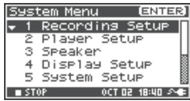
2 Use the Cursor buttons [▲][▼] to choose 3 Speaker, and press the [ENTER] button.
The Speaker screen appears.
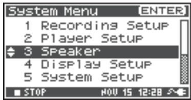
| Speaker Switch setting | Output destination |
| ON | Internal speakers |
| Line output jacks | |
| Digital output jack | |
| Headphones | |
| OFF | Line output jacks |
| Digital output jack | |
| Headphones |
- The value in boldface is the default value.

- Note that sound will not be output from the internal speakers if headphones are connected. If you want to use the internal speakers, you must disconnect the headphones.
- You cannot monitor with the internal speakers while recording. You will need to monitor through headphones.
- For more about system settings, refer to "System Setup" (p. 60).
Playing Back
Normal Playback
After performing the steps described in "Connections Before Playback" (p. 41) and "Setup Before Playback" (p. 43), proceed as follows.
1 Select the project that you want to play.
From the Main screen, press the [ENTER/FINDER] button.
2 In the Finder screen that appears, use the Cursor buttons [▲] [▼] or the [SCRUB/VALUE] dial to select a project. For more about the Finder screen, refer to "Manipulating a Project (Finder)" (p. 48).
3 Press the [PLAY] button.
The selected project will play.
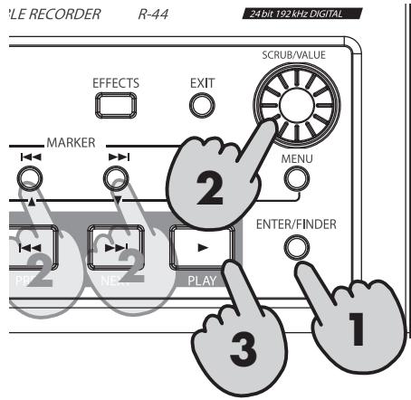
4 Slowly turn the Monitor level knob to the desired volume for listening.
- Projects with names beginning with ". ." are ignored and are not shown.
- If Japanese (double-byte) characters are used in the project name, it will not be displayed correctly. We recommend using file names that do not include Japanese (double-byte) characters so that they are easy to recognize.
- Projects whose filename extension is not. pjt or. wav will be ignored and will not be shown.
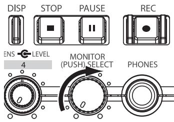
Markers
You can assign markers at desired locations in a project. Then you can use the Maker [▶] button or Maker [▶] button to move backward or forward to a marker location.
- You can use the Mark function only while playing (while the Main screen is displayed) or while recording.
1
Use the [NEXT] button, [PREV] button or the [SCRUB/VALUE] dial to find the location where you want to assign a marker.
Play, fast-forward (press and hold the [NEXT] button), or rewind (press and hold the [PREV] button) the project to the location where you want to assign a marker.
2
Press the [MARK] button at the location where you want to assign a marker.
The display indicates the number of markers, as shown in the figure at right. Markers are numbered sequentially starting from the beginning of the project.
You can assign up to 99 markers.
Repeat steps 1 and 2 to assign markers as desired.
- When the song ends, the number of passed markers becomes E .
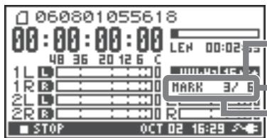
Number of markers in the project
Marker information
Number of markers you've passed
3
After assigning one or more markers, proceed as follows.
You can use these operations either while playing or while stopped.
Maker [i] button
Moves to the marker immediately before the current location (previous marker).
Maker [▶▶] button
Moves to the marker immediately following the current location (next marker).
[CLEAR] button
Deletes the markers that you set with the [MARK] button. Markers are deleted consecutively, starting with the marker immediately before the current location.
Repeat Playback (A-B REPEAT)
You can repeatedly play between two points (A-B) in a project. Simply assign points A and B during playback, and the playback will repeat between points A and B.
Play the project.
During playback, press the [A-B REPEAT] button once. The [A-B REPEAT] button blinks, and that location becomes the starting point (A) for repeat playback.
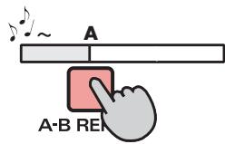
- If you press the [STOP] button after assigning point A but before assigning point B, point A will be deleted.
2 Press the [A-B REPEAT] button once again.
The [A-B REPEAT] button stays lit, and that location becomes the end point (B) for repeat playback.
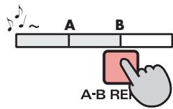
Playback automatically repeats between the points you specified in steps 1 and 2.
To cancel repeat playback, press the [A-B REPEAT] button after points A and B have already been assigned. The [A-B REPEAT] button goes out, and repeat playback is cancelled.
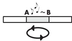
Please note
- If you press the [STOP] button after assigning point A but before assigning point B, point A will be deleted.
- If the song plays all the way to the end after assigning point A, playback will repeat between point A and the end of the song.
- If you press the [STOP] button during repeat playback, playback stops and the repeat region (A-B) settings are cleared.
The R-44 saves projects as files on an SD memory card. You can select a project from numerous folders or projects within folders to manipulate, i.e., to play, delete, or copy.
Finder functions
| Menu | Operation | Page |
| Select | Select and load a project. | p. 48 |
| Rename | Rename a project. | p. 49 |
| Copy | Copy the selected project. | p. 50 |
| Move | Move the selected project to a different folder. | p. 51 |
| Delete | Delete a project. | p. 52 |
| Make Folder | Create a new folder. | p. 53 |
| Repair | Repair a project. | p. 54 |
Selecting a Project (Select)
Press the [ENTER/FINDER] button when a project is playing or stopped and the Main screen (p. 18) is shown on the display. The Finder screen shown in the figure is displayed.
Projects are shown in descending alphabetical order. SD represents the SD memory card.
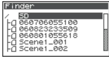
2 In the Finder screen, use the Cursor buttons [▲][▼] or the [SCRUB/VALUE] dial to select the desired project. Then press the [ENTER] button.
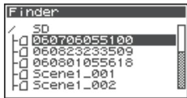

When a folder is selected, you can press the Cursor button [▶] to move into the selected folder (i.e., move to a lower-level folder).
If you want to move back to the upper-level folder, press the Cursor button [ ].
3 When the screen at right is displayed, use the Cursor buttons [▲][▼] to select 1 Select. Then press the [ENTER] button.
The project is selected, and you are returned to the Main screen.
Alternatively, with a project selected (step 2), you can press the [PLAY] button (instead of pressing the [ENTER] button) to play the selected project. You are returned to the Main screen when playback begins.
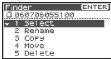
Renaming a Project (Rename)

Press the [ENTER/FINDER] button while the Main screen is shown in the display. The Finder screen shown in the figure is displayed.
Projects are shown in descending alphabetical order.
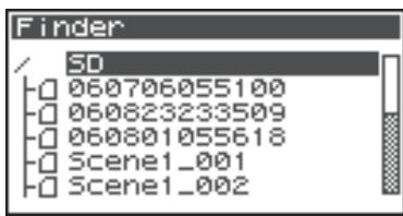

In the Finder screen, use the Cursor buttons [▲][▼] or the [SCRUB/VALUE] dial to select the project you want to rename. Then press the [ENTER] button.
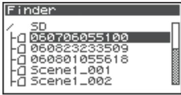

When a folder is selected, you can press the Cursor button [▶] to move into the selected folder (i.e., move to a lower-level folder).
If you want to move back to the upper-level folder, press the Cursor button [ ].

When the screen shown in the figure is displayed, use the Cursor buttons [▲] [▼] to choose 2 Rename. Then press the [ENTER] button.
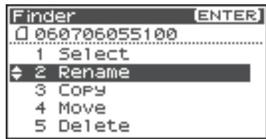

Use the Cursor buttons [ ] [▶] to move the cursor through the characters of the project name or folder name shown on the display. Place the cursor on the character that you want to change, and then use the Cursor buttons [▲] [▼] or the [SCRUB/VALUE] dial to change the character.
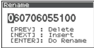
Use the [PREV] button to delete a character and the [NEXT] button to insert a character. Use these buttons to edit the name as desired.
When finished editing the name, press the [ENTER] button.
- If you decide to cancel without renaming, press the [EXIT] button before you press the [ENTER] button.
Do not turn off the power while a project is being renamed.
- When renaming a project, it cannot be given the name of an existing project. Doing so will produce an error.

Copying a Project (Copy)

Press the [ENTER/FINDER] button while the Main screen is shown in the display. The Finder screen shown in the figure is displayed.
Projects are shown in descending alphabetical order.
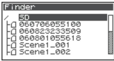

In the Finder screen, use the Cursor buttons [▲] [▼] or the [SCRUB/VALUE] dial to select the copy-source project (the project you want to copy). Then press the [ENTER] button.
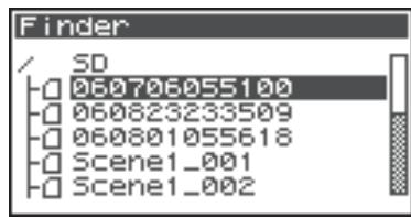

When a folder is selected, you can press the Cursor button [▶] to move into the selected folder (i.e., move to a lower-level folder).
If you want to move back to the upper-level folder, press the Cursor button [ ].

When the screen shown in the figure is displayed, use the Cursor buttons [▲] [▼] to select 3 Copy. Then press the [ENTER] button.
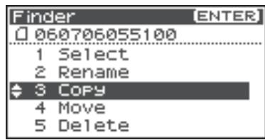

Use the Cursor buttons [▲] [▼] or the [SCRUB/ VALUE] dial to select the copy-destination folder (the folder where you want to copy the project). Then press the [ENTER] button to execute the Copy operation. You can select folders or the root folder (SD) as the copy destination.
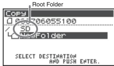
- If you decide to cancel without copying, press the [EXIT] button.
Do not turn off the power while a project is being copied.
- If the copy destination contains an identically named project, a number such as -1 or -2 is appended to the name of the copied project.
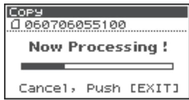
Moving a Project (Move)

Press the [ENTER/FINDER] button while the Main screen is shown in the display. The Finder screen shown in the figure is displayed.
Projects are shown in descending alphabetical order.


In the Finder screen, use the Cursor buttons [▲] [▼] or the [SCRUB/VALUE] dial to select the project that you want to move. Then press the [ENTER] button.
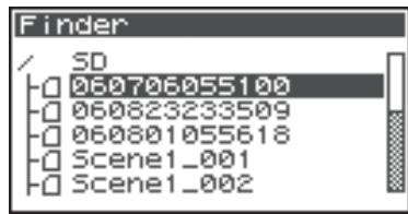

When a folder is selected, you can press the Cursor button [▶] to move into the selected folder (i.e., move to a lower-level folder).
If you want to move back to the upper-level folder, press the Cursor button [ ].

When the screen shown in the figure is displayed, use the Cursor buttons [▲] [▼] to select 4 Move. Then press the [ENTER] button.
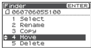

Use the Cursor buttons [▲] [▼] or the [SCRUB/ VALUE] dial to select the destination folder (the folder where you want to move the project). Then press the [ENTER] button to execute the Move operation. You can also select the root folder (SD) as the destination.
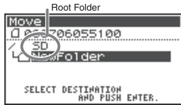
- If you decide to cancel without moving, press the [EXIT] button.
Do not turn off the power while a project is being moved.
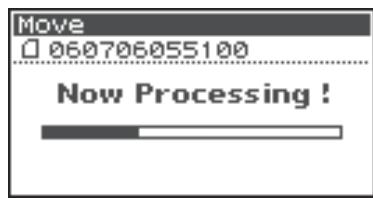
Deleting a Project (Delete)

Press the [ENTER/FINDER] button while the Main screen is shown in the display. The Finder screen shown in the figure is displayed.
Projects are shown in descending alphabetical order.
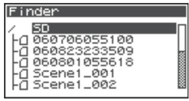

In the Finder screen, use the Cursor buttons [▲][▼] or the [SCRUB/VALUE] dial to select the project you want to delete. Then press the [ENTER] button.
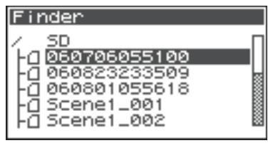

When a folder is selected, you can press the Cursor button [▶] to move into the selected folder (i.e., move to a lower-level folder).
If you want to move back to the upper-level folder, press the Cursor button [ ]

When the screen shown in the figure is displayed, use the Cursor buttons [▲] [▼] to select 5 Delete. Then press the [ENTER] button.
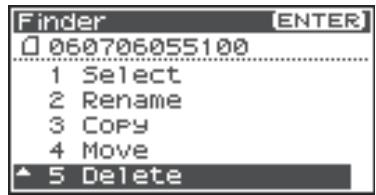

The screen shown in the figure is displayed. Press the [ENTER] button to execute the Delete operation.
- If you decide to cancel without executing, press the [EXIT] button before you press the [ENTER] button.
Do not turn off the power while a project is being deleted.
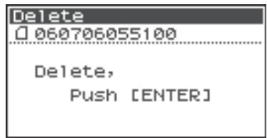
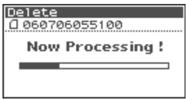
Creating a New Folder (Make Folder)
1
Press the [ENTER/FINDER] button while the Main screen is shown in the display. The Finder screen shown in the illustration will appear.
Projects are shown in descending alphabetical order.
2
In the Finder screen, use the Cursor buttons [▲][▼] or the [SCRUB/VALUE] dial to select root folder (SD) located at the top level.
Then press the [ENTER] button.
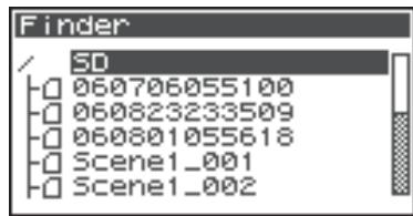
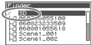

When a folder is selected, you can press the Cursor button [▶] to move into the selected folder (i.e., move to a lower-level folder).
If you want to move back to the upper-level folder, press the Cursor button [ ]
3
When the screen shown in the figure is displayed, use the Cursor buttons [▲][▼] to select 2 Make Folder. Then press the [ENTER] button.
4
When the screen shown in the figure is displayed, press the [ENTER] button to confirm the operation.
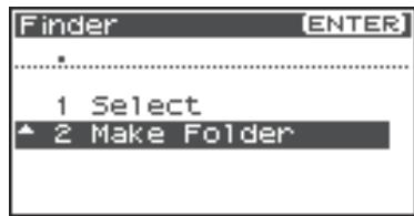
Do not turn off the power while a folder is being created.


5
A folder named NewFolder is created.
Projects are shown in alphabetical order, and folders are shown in alphabetical order after the projects.
Use the Cursor buttons [▲][▼] or the [SCRUB/VALUE] dial to verify that the new folder was created.
If an identically named folder already exists, a number will be added to the name of the newly created folder, e.g., NewFolder-1, NewFolder-11, NewFolder-111, etc.
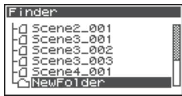
Repairing a Project (Repair)
This feature allows you to repair files that cannot be played because of an accident during recording, such as mistakenly disconnecting an AC adaptor or removing the SD memory card.
1
Press the [ENTER/FINDER] button while the Main screen is shown in the display. The Finder screen shown in the illustration will appear.
Projects are shown in descending alphabetical order.
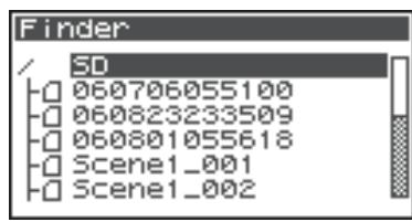
2
In the Finder screen, use the Cursor buttons [▲][▼] or the [SCRUB/VALUE] dial to select the project that you want to repair. Then press the [ENTER] button.
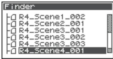

When a folder is selected, you can press the Cursor button [▶] to move into the selected folder (i.e., move to a lower-level folder).
If you want to move back to the upper-level folder, press the Cursor button [ ]
3
When the screen shown in the figure is displayed, use the Cursor buttons [▲] [▼] to select 6 Repair. Then press the [ENTER] button.
- "6 Repair" is displayed only when the R-44 detects a damaged song.
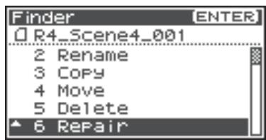
4
When the screen shown in the figure is displayed, press the [ENTER] button to confirm the operation.
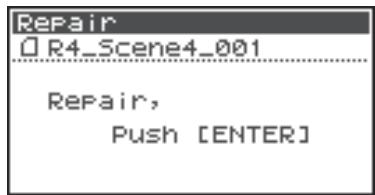
-
Do not turn off the power or remove the SD memory card while a project is being repaired.
-
This feature cannot repair all projects.
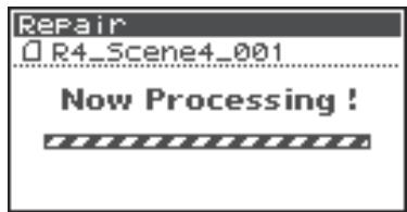
The R-44 provides five types of effects. You can apply an effect to the incoming sound as it is being recorded, or you can apply an effect to the playback. You can also change the effect settings for each channel.
- Effects are not available when the R-44 is operating at 192 kHz.
Effect types provided on the R-44
| No. | Effect name | Effect | Page |
| 0 | No Effect | No effects are applied. Use this setting if you want to preserve the effect on/off setting of each channel but do not want effects to be applied. | - |
| 1 | 3-Band EQ | This effect is a three-band equalizer. | p. 58 |
| 2 | Graphic EQ | You can adjust the gain of six fixed-frequency bands. | p. 58 |
| 3 | Noise Gate | This effect minimizes the noise that might be heard in silent regions as well as low-frequency noise. | p. 58 |
| 4 | Enhancer | By adding a phase-shifted sound to the direct sound, this effect sharpens the definition of the sound and pushes it toward the foreground. | p. 59 |
| 5 | Comp&DeEsser | This effect cuts the sibilance that can be obtrusive in a vocal, making the sound smoother. It also reduces the difference between loud and soft sounds, making the level more consistent. The compressor evens out the level differences between loud and soft sounds. The de-esser reduces the unpleasant sibilance (exaggerated “s” sound) that is sometimes present in a vocal. | p. 59 |
| 6 | MS-Mic | This effect converts sound recorded on an MS (Mid-Side type) microphone to stereo. | p. 59 |
If you apply an effect while recording, the volume and tone of the recorded sound will be different than the original sound.
Before applying an effect aggressively during recording, you should monitor the sound through headphones in recording standby mode to make sure that the sound is not clipped or distorted. We recommend that you make a test recording.
For details on the settings, refer to "Applying Effects" (p. 56).
When effects are operating, the Effect button lights.

What is an effect?
On the R-44, an "effect" is a process that digitally transforms the sound, giving it greater clarity or impact. Effects can also make the sound more intelligible or reduce undesirable noise.

What is clipping?
Applying an effect or boosting the level may increase the sound level (volume) beyond the maximum that a device can handle; this occurrence is called clipping. Loud sounds may be accompanied by distortion or crackly noises.

What is an MS mic?
An MS mic creates stereo sound by combining sound from a main microphone (unidirectional) that records central sounds (mid-signal: M) and a bi-directional microphone that records lateral sounds (side signal: S).
Applying Effects
You can adjust the R-44's effects not only while in standby for recording or playback, but also while you are listening to the sound during actual playback or recording.
This section explains how to adjust the effect settings during playback or in recording standby mode.
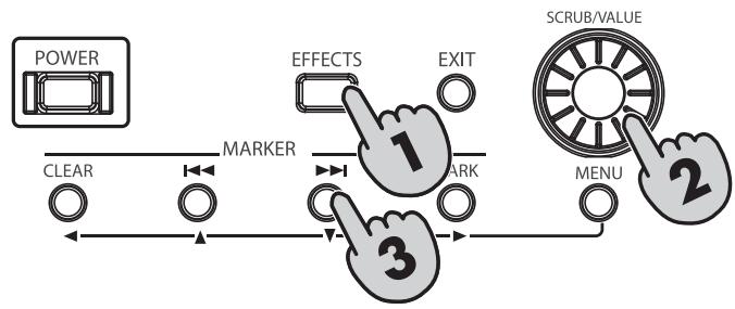
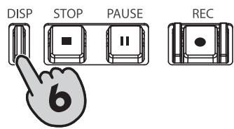
Press the [EFFECTS] button.
The Effects setup screen is shown on the display.
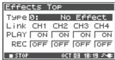
2 Use the [SCRUB/VALUE] dial to select the desired effect type.
For details on each effect type, refer to "Effects" (p. 58).
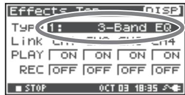
3 Press the Cursor button [ ]. The cursor will move to the "Link" field.
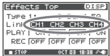
4 Use the [SCRUB/VALUE] dial to specify the channels to be linked.
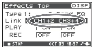
| CH1 CH2 CH3 CH4 | The effect on/off setting and effect parameters are set independently for each channel. |
| CH1+2 CH3+4 | The effect on/off setting and effect parameters are linked for channels 1 and 2 and for channels 3 and 4. Choose this setting if the project uses channels 1 and 2 and channels 3 and 4 as stereo pairs. |
| CH1+2+3+4 | The effect on/off setting and effect parameters are linked for all channels. |
5 In the same way, set the "PLAY" and "REC" fields.
PLAY
| OFF | The effect is not applied during playback |
| ON | The effect is applied during playback |
REC
| OFF | The effect is not applied during recording |
| ON | The effect is applied during recording |
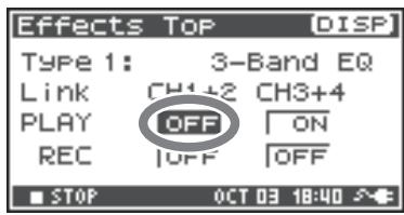
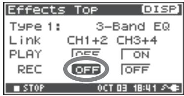
6 Press the [DISP] button.
The effect parameter screen is shown on the display.
- The effect parameter screen does not appear when 0: No Effect is selected as the type.
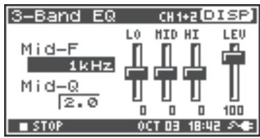
7 Use the Cursor buttons [▲][▼][〈] [▶] and the [SCRUB/VALUE] dial to set each effect parameter.
8 If you selected "CH1 CH2 CH3 CH4" or "CH1+2 CH3+4" in the "Link" field, press the [DISP] button.
The next channel (or pair of channels) will appear in the display.
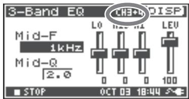

While selecting effects or setting effect parameters, you can return to the previous screen by pressing the [EXIT] button. The effect settings you make are stored until you change them. However, if you change the effect type (Type), the settings you made are reset to the default values.
9 When finished setting the effect parameters, press the [EXIT] button to return to the Main screen.
Each effect has various parameters that you can adjust to alter the character of the effect. The settings you make are stored even when the R-44's power is switched off. However, if you change the effect type, these settings are reset to the default values.
Effects
1: 3-Band EQ
| No. | Parameter name | Range of values | Default values | Explanation |
| 1 | MID-F | 200 Hz, 250 Hz, 315 Hz, 400 Hz, 500 Hz, 630 Hz, 800 Hz, 1 kHz, 1.25 Hz, 1.6 kHz, 2 kHz, 2.5 kHz, 3.15 kHz, 4 kHz, 5 kHz, 6.3 kHz | 1 kHz | Specifies the center frequency of the mid-range equalizer. |
| 2 | MID-Q | 0.5, 1.0, 2.0, 4.0, 8.0 | 2.0 | Sets the range of the region centered on the Mid Freq for which the gain will change. Higher values narrow the region in which the change occurs. |
| 3 | LOW | -12 dB–0 dB–+12 dB | 0 dB | Adjusts the gain of the low-range equalizer. |
| 4 | MID | -12 dB–0 dB–+12 dB | 0 dB | Adjusts the gain of the mid-range equalizer. |
| 5 | HIGH | -12 dB–0 dB–+12 dB | 0 dB | Adjusts the gain of the high-range equalizer. |
| 6 | LEVEL | 0–120 | 100 | Adjusts the overall volume. |
2: Graphic EQ
| No. | Parameter name | Range of values | Default values | Explanation |
| 1 | 125 Hz | -12 dB–0 dB–+12 dB | 0 dB | Adjusts the gain at 125 Hz. |
| 2 | 250 Hz | -12 dB–0 dB–+12 dB | 0 dB | Adjusts the gain at 250 Hz. |
| 3 | 500 Hz | -12 dB–0 dB–+12 dB | 0 dB | Adjusts the gain at 500 Hz. |
| 4 | 1 kHz | -12 dB–0 dB–+12 dB | 0 dB | Adjusts the gain at 1 kHz. |
| 5 | 2 kHz | -12 dB–0 dB–+12 dB | 0 dB | Adjusts the gain at 2 kHz. |
| 6 | 4 kHz | -12 dB–0 dB–+12 dB | 0 dB | Adjusts the gain at 4 kHz. |
| 7 | Level | 0–120 | 100 | Adjusts the overall volume. |
3: Noise Gate
| No. | Parameter name | Range of values | Default values | Explanation |
| 1 | LO-CUT | OFF, 40 Hz, 55 Hz, 63 Hz, 80 Hz, 100 Hz, 125 Hz, 160 Hz, 200 Hz, 250 Hz, 315 Hz, 400 Hz, 500 Hz, 630 Hz, 800 Hz, 1 kHz | 100 Hz | Cuts unwanted low-frequency noise such as wind. |
| 2 | THRESHOLD | OFF, 1–100 | 20 | Specifies the volume threshold below which the sound will be cut. |
| 3 | LEVEL | 0–120 | 100 | Adjusts the overall volume. |
4: Enhancer
| No. | Parameter name | Range of values | Default values | Explanation |
| 1 | SENSE | 0–100 | 50 | Adjusts the sensitivity of the enhanc-er effect. |
| 2 | MIX | 0–100 | 50 | Adjusts the amount of phase-shifted sound that is to be mixed with the in-put. |
| 3 | LEVEL | 0–120 | 100 | Adjusts the overall volume. |
5: Comp&DeEsser
| No. | Parameter name | Range of values | Default values | Explanation |
| 1 | DE-ESSER | OFF, ON | ON | Turn this ON to reduce unpleasant sibilance. |
| 2 | THRESHOLD | 0–100 | 50 | Sets the volume (threshold level) at which the compressor begins to operate. Compression is applied to the input when it exceeds this level. Lower threshold settings mean that the compressor is applied even at lower levels. |
| 3 | RATIO | 1.0:1, 1.2:1, 1.5:1, 2.0:1, 2.8:1, 4.0:1, 8.0:1, 16.0:1, Inf:1 | 4.0:1 | Adjusts the ratio at which the sound is compressed when the input exceeds the threshold level. Higher ratios mean that the sound is compressed more strongly. |
| 4 | ATTACK | 6–100 ms | 10 ms | Adjusts the time over which the amount of compression specified by Ratio is reached once compression is triggered when the input exceeds the threshold level. Higher Attack settings mean that compression is applied more slowly. |
| 5 | RELEASE | 50–5000 ms | 100 ms | Adjusts the time until compression is released once the input falls below the threshold level. Higher Release settings mean that the sound reverts to its uncompressed state more slowly. |
| 6 | GAIN | -6.0 dB→+18.0 dB (The value will change in steps of 0.5 dB) | 0.0 dB | Adjusts the gain following compression. |
| 7 | LEVEL | 0–120 | 100 | Adjusts the overall volume. |
6: MS-Mic
| No. | Parameter name | Range of values | Default values | Explanation |
| 1 | Wide | 0–100 | 80 | Adjusts sound dispersion. |
| 2 | Level | 0–120 | 100 | Adjusts the overall volume. |
- You can adjust the stereo dispersion during recording or playback. This case is limited to MS mics that can directly output the mid and side signals. Connect the mid-signal to CH1 (CH3) and the side signal to CH2 (CH4).
You can make settings related to the R-44's system when performing initial settings for recording or playback. Press the [MENU] button to enter the system setup menu. Refer to "Example Operations" (p. 61) for setup procedures.
| No. | Menu item | Summary | Page |
| 1 | Recording Setup | Allows you to make recording settings. | p. 61 |
| 2 | Player Setup | Allows you to make playback settings. | p. 61 |
| 3 | Speaker | Turns the speaker on/off. | p. 61 |
| 4 | Display Setup | Allows you to make display settings. | p. 61 |
| 5 | System Setup | Allows you to make settings to specify how the R-44 operates. | p. 61 |
| 6 | Date & Time | Allows you to set the date and time of the R-44's internal calendar. You can specify the year, month, and date (day). | p. 62 |
| 7 | Project Name | The R-44 automatically assigns a name to project files that are created when recording. You can set how this name will be assigned. | p. 63 |
| 8 | SD Card | Allows you to format and check on the SD memory card. | p. 64 |
| 9 | Factory Reset | Restores the R-44 to the factory default settings. | p. 65 |
Example Operations
Recording Setup
You can use the same procedure to make the settings listed below. As an example, we will show how to make Recording Setup settings.
1 Recording Setup
2 Player Setup
3 Speaker
4 Display Setup
5 System Setup
Press the [MENU] button.
The System Menu screen is shown on the display.
2 Use the Cursor buttons [▲][▼] to choose 1 Recording Setup, and press the [ENTER] button.
The Recording Setup screen is shown.
3 Use the [SCRUB/VALUE] dial to choose the Input Select value.
The setting is applied as soon as you select it. You do not need to press the [ENTER] button.
4 Use the Cursor buttons [▲] [▼] to select Rec Freq.
5 Use the [SCRUB/VALUE] dial to select the Rec Freq. value.
In the same way, use the Cursor buttons [▲][▼] and the [SCRUB/VALUE] dial to select and set the remaining items.
7 When finished making settings, press the [EXIT] button.
You are returned to the System Menu screen.
Press the [EXIT] button again to return to the Main screen.
If you want to make other system settings, use the Cursor buttons [▲][▼] to select the desired menu item.
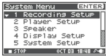
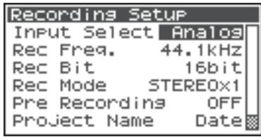
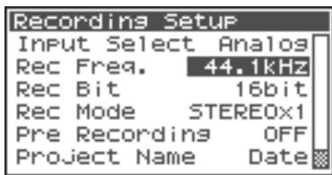
Date & Time Settings
Press the [MENU] button.
The System Menu screen is shown on the display.

2 Use the Cursor buttons [▲] [▼] to select 6 Date & Time, and press the [ENTER] button.
The Date & Time screen is shown.
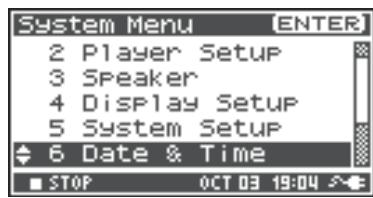
3 Use the Cursor buttons [▲][▼][<] [▶] and the [SCRUB/VALUE] dial to set the date and time.
When finished making settings, press the [EXIT] button.
You are returned to the System Menu screen.
- If you decide to cancel, press the [EXIT] button.
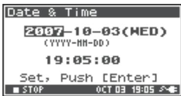
4 Press the [EXIT] button again to return to the Main screen.
If you want to make other system related settings, use the Cursor buttons [▲] [▼] to select the desired menu item.
Project Name Settings
Press the [MENU] button.
The System Menu screen is shown on the display.

2 Use the Cursor buttons [▲][▼] to select 7 Project Name, and press the [ENTER] button.
The Project Name screen is shown.
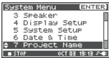
3 Use the Cursor buttons [▲] [▼] to select the name you want to edit, and press the [ENTER] button.
A screen for editing the project name is shown.
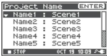
4 Use the Cursor buttons [▲][▼][▲][▼], [SCRUB/ VALUE] dial, [PREV] button, and [NEXT] button to edit the name.
When finished, press the [ENTER] button. You are returned to the Project Name screen.
- If you decide to cancel, press the [EXIT] button.
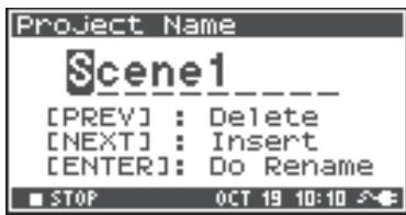
Available characters
(space) !#$%&'()+,-.01234546789;=@
ABCDEFGHIJKLMNOPQRSTUVWXYZ[]^_abcdefghijklmnpqrstuvwxyz{}
Press the [EXIT] button again to return to the Main screen.
If you want to make other system related settings, use the Cursor buttons [▲] [▼] to select the desired menu item.
Formatting and Checking the SD Memory Card
Press the [MENU] button.
The System Menu screen is shown on the display.

2 Use the Cursor buttons [▲] [▼] to select 8 SD Card, and press the [ENTER] button.
The SD Card Utility screen is shown.
- If you decide to cancel, press the [EXIT] button.
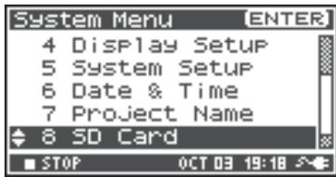
3 Use the Cursor buttons [▲][▼] to select either "Format" or "Check," and press the [ENTER] button.
For details, refer to "8 SD Card" (p. 70).
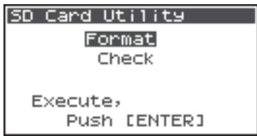
4 The "Are you sure?" confirmation message appears. Use the Cursor buttons [▲][▶] to select "Yes" if you are sure you want to execute or "No" if you decide to cancel without executing.
Then press the [ENTER] button.

The message shown at right is shown during processing. Do not turn off the power during processing.

When processing has completed, you are automatically returned to the System Menu screen.
Press the [EXIT] button again to return to the Main screen.
If you want to make other system related settings, use the Cursor buttons [▲] [▼] to select the desired menu item.
- When first using an SD memory card with the R-44, be sure to format it with the R-44.
Executing Factory Reset (Restoring Factory Default Settings)
1 Press the [MENU] button.
The System Menu screen is shown on the display.
![ROLAND R-44 - Press the [MENU] button. - 1](/content/2025/01/130964/images/53f5b35ce68dc7e0da2d24ba8d7b56dad3f874fe1d5b2e330b72477859aa68b3.jpg)
2 Use the Cursor buttons [▲] [▼] to select 9 Factory Reset, and press the [ENTER] button.
The Factory Reset screen is shown.
![ROLAND R-44 - Use the Cursor buttons [▲] [▼] to select 9 Factory Reset, and press the [ENTER] button. - 1](/content/2025/01/130964/images/5859c747d1e4019f6099fc8e9d1f08571168b9cb3588bb408e38f39f3d393647.jpg)
3 Press the [ENTER] button to perform Factory Reset.
- If you decide to cancel, press the [EXIT] button.
![ROLAND R-44 - Press the [ENTER] button to perform Factory Reset. - 1](/content/2025/01/130964/images/3765a25152e1cc38713428e8eeaccbf6fec5bb254e1e9acad57e19118b6057b0.jpg)
4 The "Are you sure?" confirmation message appears. Use the Cursor buttons [▲][▶] to select "Yes" if you are sure you want to execute or "No" if you decide to cancel without executing.
Then press the [ENTER] button.
![ROLAND R-44 - The "Are you sure?" confirmation message appears. Use the Cursor buttons [▲][▶] to select "Yes" if you are sure you want to execute or "No" if you decide to cancel without executing. - 1](/content/2025/01/130964/images/e1167afbdd181141017f468144dd535c8d19c05be1c6f48468683de5952fd425.jpg)
When processing has completed, you are automatically returned to the System Menu screen.
The message shown at right is shown during processing. Do not turn off the power during processing.
![ROLAND R-44 - The "Are you sure?" confirmation message appears. Use the Cursor buttons [▲][▶] to select "Yes" if you are sure you want to execute or "No" if you decide to cancel without executing. - 2](/content/2025/01/130964/images/aa8b83815f23a4d8cf6603557ceadf00fbf2858cd52e4ffe936010e1715e3bf0.jpg)
Press the [EXIT] button again to return to the main screen.
If you want to make other system related settings, use the Cursor buttons [▲][▼] to select the desired menu item.
System Menu
1 Recording Setup
The values in boldface are the default values.
- You cannot make Recording Setup settings during recording or playback.
- The R-44 is not able to convert previously recorded data to a different data format.
| Menu item | Value | Function | ||||||
| Input Select | Analog | This selects the type of input. Choose this setting if you want to record analog input. Connect your microphones or analog audio device to the Combo input jacks. With this setting, any input from the internal mics or the Digital input jack is ignored. | ||||||
| Digital | Choose this setting if you want to record digital input. The signal from a digital device connected to the Digital input jack is recorded. With this setting, any input from the internal mics or the Combo input jacks is ignored. The sampling frequency is specified by the Rec Freq. setting, and the bit depth by the Rec Bit setting. | |||||||
| IntMic | Choose this setting if you want to record via the internal mics. Limiter and Low cut are disabled, and SENS has three levels. | |||||||
| Dig + Ana | Choose this setting if you want to simultaneously record digital and analog input. The signal from the digital device connected to the Digital input jack and the signal from the microphones or analog audio device connected to the Combo input jacks are recorded simultaneously. For these settings, the digital input is on channels 1 and 2. Use channels 3 and 4 for the analog input. | |||||||
| Int + Ana | Choose this setting if you want to simultaneously record from the internal mics and analog input. MIC-L is on channel 1, and MIC-R is on channel 2. Use channels 3 and 4 for the analog input. Limiter and Low cut are disabled, and SENS has three levels. | |||||||
| Rec Freq. | 44.1 kHz, 48.0 kHz, 88.2 kHz, 96 kHz, 192 kHz | This sets the sampling frequency for recording. Higher sampling frequencies allow higher-quality recording but produce larger project files, meaning that there will be less available recording time on the SD memory card. The 44.1 kHz setting is sufficient when recording audio that falls within the normally audible range. This frequency is also the most suitable if you are going to load the recorded file into your computer to create a music CD. You can use the higher frequency settings when recording audio that contains a significant amount of high-frequency content from instruments such as cymbals or when you want to capture the brightness and transparency of a natural environment. * When Rec Freq. is 192 kHz, only 2-channel recording is possible. | ||||||
| Rec Bit | 16 bit, 24 bit | This sets the sample size (bit depth) for recording. A larger sample size allows the sound to be captured in greater detail but produces a larger project file, meaning that there will be less available recording time on the SD memory card. Use the 16-bit setting for normal recording. This setting allows the broadest compatibility when loading the recorded file into your computer for playback. Use the 24-bit setting if you want to capture the tonal character and ambience in greater detail, such as when recording an instrumental or vocal performance. Depending on the PC environment, you may not be able to play project files recorded in 24 bit. | ||||||
| Menu item | Value | Function | ||||||
| Rec Mode | MONOx1 | One-channel recording to one monaural file | This selects the structure of the project file that is created during recording. A monaural WAV file will be created for each channel. Choose these settings if you are using a separate microphone for the vocal and performance or for each speaker in a conversation, so that a separate file is created for each channel. These settings create monaural WAV files. If Input Select is set to Analog, you can create up to four monaural files. If Input Select is set to IntMic or Digital, you can create up to two monaural files.* You cannot select MONO x3 or MONO x4 if Input Select is set to IntMic or Digital.* You cannot select MONO x3 or MONO x4 if Rec Freq. is set to 88.2 kHz, 96 kHz, or 192 kHz. | |||||
| MONOx2 | Two-channel recording to two monaural files | |||||||
| MONOx3 | Three-channel recording to three monaural files | |||||||
| MONOx4 | Four-channel recording to four monaural files | |||||||
| STEREOx1 | Two-channel recording to one stereo file | Two channels are recorded as L and R to create a stereo WAV file.If Input Select is set to Analog, one stereo WAV file with channel 1 as L and channel 2 as R is created. The inputs to channels 3 and 4 are ignored.If Input Select is set to IntMic or Digital, one stereo WAV file is created. | ||||||
| STEREOx2 | Four-channel recording to two stereo files | If Input Select is set to Analog, a stereo file with channel 1 as L and channel 2 as R is created, and another stereo file with channel 3 as L and channel 4 as R is also created.* When Input Select is set to either IntMic or Digital or when Rec Freq. is set to 192 kHz,STEREOx2 cannot be selected. | ||||||
| 4CHx1 | Four-channel recording to one four-channel file | Channels 1-4 will be recorded as a single WAV file. Be aware that not all computer software can handle four-channel WAV files.* When Input Select is set to either IntMic or Digital or when Rec Freq. is set to 192 kHz, 4CHx1 cannot be selected. | ||||||
| MONOx1 | MONOx2 | MONOx3 | MONOx4 | STEREOx1 | STEREOx2 | 4CHx1 | ||
| 44.1 kHz | ○ | ○ | ○ * | ○ * | ○ | ○ * | ○ * | |
| 48 kHz | ○ | ○ | ○ * | ○ * | ○ | ○ * | ○ * | |
| 88.2 kHz | ○ | ○ | × | × | ○ | ○ * | ○ * | |
| 96 kHz | ○ | ○ | × | × | ○ | ○ * | ○ * | |
| 192 kHz | ○ | ○ | × | × | ○ | × | × | |
| * Cannot be used if Input Select is set to IntMic or Digital. | ||||||||
| Menu item | Value | Function |
| Pre Recording | OFF, 1-47 sec | You can specify the length of time that the sound is captured "retroactively," starting from before the moment you pressed the [REC] button. This setting specifies the number of seconds that is captured retroactively.* The maximum time depends on the sampling frequency, the sample size (bit depth), and the mode setting. |
| Rec Freq. Rec Bit Rec Mode Pre Recording (Maximum Time) | ||
| 44.1 kHz 16 MONO x1 47 | ||
| 44.1 kHz 16 STEREO x1 23 | ||
| 44.1 kHz 16 STEREO x2 11 | ||
| 48 kHz 16 STEREO x1 21 | ||
| 48 kHz 16 STEREO x2 10 | ||
| 48 kHz 24 STEREO x1 14 | ||
| 48 kHz 24 STEREO x2 7 | ||
| 88.2 kHz 24 STEREO x1 7 | ||
| 88.2 kHz 24 STEREO x2 3 | ||
| 96 kHz 24 STEREO x1 7 | ||
| 96 kHz 24 STEREO x2 3 | ||
| 192 kHz 24 STEREO x1 3 | ||
| * "Pre Recording (Maximum Time)" is approximate.* The R-44 consumes power even during pre-recording. If you are running on batteries, you should pay attention to the remaining battery charge. | ||
| Project Name | Date, Name1-8 | This specifies how names are assigned to the recorded project files. You can select to base the name on the date and time or on the Project Name that you set. If you choose Date, a project recorded at 3:45 and 12 seconds in the morning, January 2, 2007, is given the name of "070102034512". If you use the Date setting, the name of the project indicates the time that it was recorded; this is convenient when you have recorded a large number of projects and are looking for a specific one. If you choose Name, the project name is the name you set in "7 Project Name" (p. 70) plus an ascending serial number. If you specify a clearly identifiable project name, e.g., SCENE001, SCENE002, etc. the project files are grouped together. If you use the Name1-8 setting, the project name is the name you set in "7 Project Name" (p. 70) plus an ascending serial number. The serial number is incremented automatically, e.g., Scene1_001-Scene1_999, up to 999. The R-44 uses the number of the highest serial numbered project name in the current folder as the start value for the serial number. |
| Limiter link | 1/2/3/4 | The limiter is applied independently to each channel. |
| 1+2/3+4 | The limiter for channels 1 and 2 is linked. In addition, the limiter for channels 3 and 4 is linked. | |
| 1+2+3+4 | The limiter for all channels is linked. | |
| 1+2/3/4 | The limiter for channels 1 and 2 is linked. The limiter for channels 3 and 4 is applied independently. | |
| 1/2/3+4 | The limiter for channels 3 and 4 is linked. The limiter for channels 1 and 2 is applied independently. |
2 Player Setup
| Parameter | Value | Function |
| Play Mode | Single | This selects the playback mode. Only the selected project will play. |
| Sequential | All projects in the folder containing the currently selected project are played sequentially. | |
| Repeat | OFF, ON | This selects whether playback will repeat. If Play Mode is set to Single, only that project is played repeatedly. If Play Mode is set to Sequential, the projects in the folder containing the currently selected project play to the end of the list, and then the projects in that same folder play sequentially again from the beginning of the list. |
3 Speaker
| Parameter | Value | Function |
| Speaker Switch | OFF, ON | This switches the internal speakers on/off. * Even if this is set to on, no sound is played from the internal speakers during recording standby or recording. The speakers also remain silent while headphones are being used. |
4 Display Setup
| Parameter | Value | Function |
| Bright | 1-5-10 | This adjusts the display's contrast. Higher values emphasize the white areas of the display. |
| Display Timer | OFF, 2 sec, 5 sec, 10 sec, 20 sec | Sets the amount of time until the display becomes dark when no operations have been performed on the R-44. If you are operating the R-44 on battery power, use this setting to conserve battery life. |
| Button Light | Auto, Dim, Bright | Sets the button brightness. When set to Auto, the button light darkens linked to the set time of the Display Timer. |
| Illumination | OFF, ON | All buttons are dimly lit. Button positions are easily verified even in dark locations. |
5 System Setup
| Parameter | Value | Function |
| Battery Type | Alkaline, Ni-MH | Sets the type of batteries you are using. Choose the Alkaline setting if you are using alkaline batteries or Ni-MH if you are using nickel metal-hydride batteries. * If you choose a setting that does not match the type of batteries that are actually installed, the remaining battery power indication will be incorrect. |
| Ext-Power | Adaptor, 9.0/9.5/ 10.0/10.5/ 11.0/11.5/ 12.0V | Sets the final voltage when using an external power source. The "Battery Low!" message is displayed when the voltage of the external power source drops below the set voltage and if the voltage drops further, the power automatically turns off. |
| Output Sel | 4-indiv | Sets the sound output type (p. 18). The sound from each channel from LINE OUT is output without modification. |
| monitor | Sound is output according to the output assignments | |
| Sync Mode | Master | Sets the sync signal mode (p. 73). These settings are for the transmission side. |
| Slave | These settings are for the receiving side. | |
| Project File | WAV, BWF | This specifies the desired format of the project files created during recording or editing. If you select WAV, a conventional WAV file will be created. If you select BWF, a BWF file containing information about the recording time and recording device (EDIROL R-44) will be created. |
6 Date & Time
You can set the date and time.
If Project Name is set to Date, the time you specify here is used to set the date in the project name. This setting is also used for the date and time shown on the lower part of the display in the Main screen.
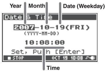
7 Project Name
You can use Name 1-8 to specify eight different name types. The project name will consist of this name plus a consecutive number of 001, 002, 003, ... appended to it. For example, in the case of the default setting Scene1, the project name will be Scene1_001.
In order to use a name you have specified here, you will need to set the Recording Setup parameter Project Name to Name 1-8.
Available characters
(space) !\$\%&'()+,-.01234546789;=@
ABCDEFGHIJKLMNOPQRSTUVWXYZ[]^_abcdefghijklmnopqrstuvwxyz{}
8 SD Card
You can format and check SD memory cards. You cannot execute "SD Card" commands during recording or playback.
| Command | Explanation |
| Format | Formats the SD memory card. All projects and folders in the SD memory card are erased; afterwards, the SD memory card is empty. * Be sure to back up your projects before you execute this command. |
| Check | Checks the SD memory card, and after reorganization, frees up any SD memory card space not used by R-44 Projects. * There is no guarantee that this command will restore the SD memory card to a normal operating state. Since this command directly manipulates the SD memory card sectors, projects may be damaged. Be sure to back up your projects before executing this command. |
9 Factory Reset
This command resets the following settings to their factory default settings. You cannot execute Factory Reset during recording or playback.
Recording Setup
Player Setup
Speaker
Display Setup
System Setup
Project Name
Effects (Type, Link, Play, Rec, Parameters)
Connecting to a Computer
You can move or copy projects recorded on the R-44 to your computer. Likewise, you can move or copy files from your computer to the SD memory card.
Connecting the R-44 to Your Computer
Using battery power will not cause a malfunction, but we recommend that you always use the AC adaptor to prevent damage to the contents of the SD memory card, which could occur if the batteries fail while the R-44 is connected to your computer.

Turn on the [POWER] switch.

Use a USB cable to connect the R-44 to your computer.
The computer will detect the R-44, and the screen shown at right is shown.
It may take several seconds for detection to occur.

- If you see the "Windows can perform the same action each time you insert a disk or connect a device with this kind of file." dialog box, click [Cancel].
The computer will detect the R-44 as follows.
| Windows Vista Windows XP Windows 2000 | When viewed from My Computer or Explorer, the R-44 appears as R-44. |
| Mac OS X | The R-44 appears as R-44 on the desktop. |
- If you connect the R-44 to your computer when using an SD memory card that was not formatted by the R-44, the name "R-44" will not be displayed. You must use an SD memory card that was formatted by the R-44.

You can copy WAV files from the R-44 to your computer, or from your computer to the R-44.
To copy a file, drag and drop it.
- Depending on the computer environment, you may not be able to play project files recorded in 24 bit or 4ch.
Disconnecting the R-44 from a Computer
The following describes how to close the connection between your computer and the R-44. You must use the procedure described below to close the connection before you disconnect the USB cable.

Do not disconnect the USB cable or power down the R-44 while it is connected to your computer.
Windows Vista, Windows XP or Window 2000
1 Close all software and windows (such as Explorer) that are referencing the SD memory card.
* If any software or windows (such as Explorer) referencing the SD memory card are open when you close the USB connection between your computer and the R-44, an error will occur and the connection will not be closed correctly.
2 In the Windows task tray, double-click the Safely Remove Hardware icon.
The Safely Remove Hardware dialog box will appear.
3 Select the item (EDIROL R-44 USB Device) that indicates the R-44.
4 In the dialog box, click [Stop].
5 When the Stop a Hardware Device dialog box appears, select the item that indicates the R-44, and click [OK].
6 When your computer indicates "Safe To Remove Hardware," you can disconnect the USB cable between the R-44 and your computer.
When you disconnect the cable, the screen shown at right will appear.
- Never switch off the R-44's power or disconnect the USB cable before you have closed the connection. Doing so may damage the SD memory card.

Macintosh OS X
1 Cancel the connection with the R-44 displayed on the desktop.
Drag the R-44 icon to the icon on the dock.
Normally, when you drag to the trash can located at the right edge of the dock, the indication changes from the trash can to allowing you to cancel the connection.
2 When the icon has disappeared from the desktop, you can disconnect the USB cable between the R-44 and your computer.
Remotely Linking Two Connected R-44 Units
You can prepare two R-44 units and connect them with control sync to record with up to 8 channels.
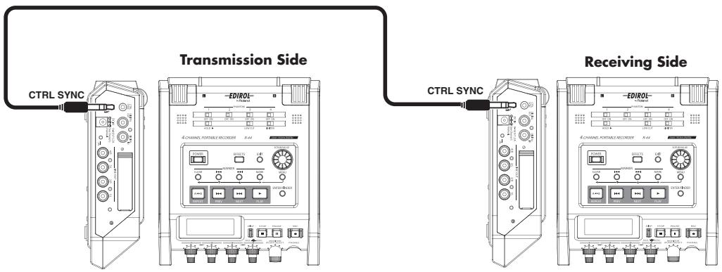
- Connections
Connect both R-44 units via the Control sync connector. A stereo mini cable is required to connect R-44 units via the R-44's Control sync connector. Please purchase separately.
- System settings
Transmission Side Setup
- Press the [MENU] button.
-
In 5 System Setup, set Sync Mode to Master.
-
For more about system settings, refer to "System Setup" (p. 60).
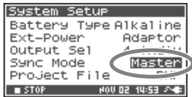
Receiving Side Setup
- Press the [MENU] button.
-
In 5 System Setup, set Sync Mode to Slave.
-
For more about system settings, refer to "System Setup" (p. 60).
This completes the settings for remote linking.
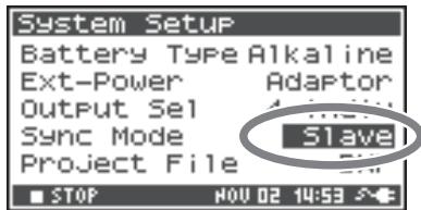
Recording
Press the [REC] button on the transmitting R-44 to start the recording.
Refer to "Recording" (p. 29) for information about recording settings.
Recording standby can also be linked remotely.
Refer to "Recording standby" (p. 31) for information about recording standby.
- When using remotely linked recording, be sure that Rec Freq. in Recording Setup is the same for both R-44 units.
- Remote linking does not guarantee the exact same REC start time.
- The receiving R-44 cannot record from digital input.
This section explains the most important messages that may appear in the R-44's display
| Message | Status |
| Int-Batt Low!The remaining charge for the internal battery is low.The internal battery must be replaced. If the battery charge is insufficient, the internal clock will become inaccurate but you can record, play and manipulate the other functions correctly. Please contact one of the service locations listed on the warranty card to have the battery replaced. | Battery Low!The remaining charge for the batteries or the external power source is low.Install fresh batteries, change the external power source, or use the AC adaptor. |
| SD bufferingThe recording buffer has almost reached capacity. Refer to p. 21 for details. | SD buffering |
| SD Card Slow!The recording buffer has reached capacity. Recording does not stop, but some sound is not recorded. This message will not disappear until a button is pressed. If this message is displayed again, it is possible that SD memory card processing capability has decreased. Format the SD memory card.Refer to p. 21 for details. | SD UnformattedThis message is displayed if an SD memory card was formatted in a file format that the R-44 cannot read. Please format the SD memory card. |
| SD Card Full!There is insufficient free space on the SD memory card.Transform project files to your computer to free up more space. | SD Card Full!There is insufficient free space on the SD memory card.Transform project files to your computer to free up more space. |
| SD Card LockedThe memory card is locked. Remove the memory card and unlock it. | SD Card LockedThe memory card is locked. Remove the memory card and unlock it. |
| SD Card ErrorAn error occurred while accessing the memory card. The memory card may be corrupted. | SD Card ErrorAn error occurred while accessing the memory card. The memory card may be corrupted. |
| Over pri#999This message is displayed if you press the record button when a project name with a number of 999 already exists. You cannot record in this state. You need to change the project name before you can record. | Over pri#999This message is displayed if you press the record button when a project name with a number of 999 already exists. You cannot record in this state. You need to change the project name before you can record. |
| Project exists!An identically named project already exists.Create the project using a different name. | Project exists!An identically named project already exists.Create the project using a different name. |
| File-Sys Error!File-Sys Error!A problem has occurred with the file system. | File-Sys Error!A problem has occurred with the file system. |
| Name too long!The project name is too long.This message is displayed if the project name newly created when you copy a project is too long.You'll need to shorten the name of the source project. | Name too long!The project name is too long.This message is displayed if the project name newly created when you copy a project is too long.You'll need to shorten the name of the source project. |
| Improper Proj.The R-44 cannot handle this project. | Improper Proj.The R-44 cannot handle this project. |
| HOLD ONThe HOLD switch is on.This message is displayed if you attempt to operate the R-44 while the HOLD switch is on. | HOLD ONThe HOLD switch is on.This message is displayed if you attempt to operate the R-44 while the HOLD switch is on. |
| Now RecordingsThe R-44 is recording now.This message is displayed if you attempt to operate the R-44 during recording. If you need to perform an operation, you must first stop recording. | Now RecordingsThe R-44 is recording now.This message is displayed if you attempt to operate the R-44 during recording. If you need to perform an operation, you must first stop recording. |
| Now PlayingThe R-44 is playing now.This message is displayed if you attempt to operate the R-44 during playback. If you need to perform an operation, you must first stop playback. | Now PlayingThe R-44 is playing now.This message is displayed if you attempt to operate the R-44 during playback. If you need to perform an operation, you must first stop playback. |
If you experience difficulties, read this section first. It contains tips on how to resolve various problems.
Problems with the Computer
Cannot close the connection with the R-44
When using Windows and if Explorer or any other software referencing the SD memory card is open when you attempt to close the USB connection between the R-44 and your computer, the error message "An error occurred while removing USB mass storage device - Unable to close device 'unspecified volume." Please execute Stop Device again later." will appear, and you will be unable to disconnect the R-44. Close all software or windows that are referencing the SD memory card. Then execute "Safely Remove Hardware" (p. 72) once again.
Problems with Recording
Cannot record
You cannot record correctly if the input level specified with the Input level knobs is too low. Please set the input level correctly.
Refer to: "Adjusting the input levels" (p. 30)
When recording from connected microphones, make sure that the microphones are properly connected to the XLR input connectors.
Also check the setting of the Phantom power switch.
Refer to: "Phantom Power Switches [PHANTOM POWER]" (p. 10)
You cannot record correctly if the Input Select system setting is wrong.
Refer to: "System Setup" (p. 60)
Recorded audio is distorted
The audio is distorted if the input level is too high. Refer to "Adjusting the input levels" (p. 30), and use the Input level knobs to adjust the level appropriately.
In some cases, the sound may be distorted because an effect has been applied while recording. You should adjust the input level with the effect applied. Adjust the effect parameters so that distortion does not appear.
Pan (stereo image) is not stored correctly
If the limiter is turned on, it will respond to the levels of each channel, meaning that when the level of a sound located toward the right (or left) side increases, the limiter for that channel will limit the volume. If you're recording in stereo, the result will be that the left and right volume difference will diminish, causing the pan (stereo image) to move toward the center.
- Panning can be correctly recorded by linking the limiters of the channels being recorded in stereo using the Limiter Link.
Refer to: "1 Recording Setup" (p. 66)
If using the Comp&DeEsser effect with channel linking (LINK) set separately for CH1, CH2, CH3, and CH4, and the compressor begins to operate on CH1 (left), this will eliminate the level difference with CH2 (right), causing the pan (stereo image) to move toward the center.
- In this case, set the LINK setting to CH1 + 2 or CH3 + 4 so that whenever compression starts being applied to CH1 (left), it will be applied to CH2 (right) at the same time.
Refer to: "Setting the Color of Sound (Effects Settings)" (p. 55)
Also, the stereo image will not be recorded correctly if the input level knob settings differ significantly between L and R, so that the levels are not balanced correctly.
Even though the recording levels are set, the sound is distorted when an effect is turned on
Since some effects work by emphasizing a portion of the sound, this may increase the volume of the overall song, thereby causing clipping (distortion). You may take either of the following two actions.
- Lower the level (LEV) values for each effect parameter
The overall volume will decrease, but the character of the effect will be maintained.
Refer to: "Setting the Color of Sound (Effects Settings)" (p. 55)
- Lower the input level to decrease the volume before applying the effect
This adjustment is easy to make, but may change the resulting character of the effect.
The SD Card Slow! message is shown
- Writing access to the SD memory card has slowed down.
As you repeatedly write and delete project files, the files on the SD memory card become fragmented, and this slows down the processing speed.
If making important recordings, you should consistently delete all projects together when finished with them. Repeated deletion of smaller pieces of data causes the SD memory card to become fragmented, possibly causing recording to fail.
- The write speed for the SD memory card is specified to be slow.
The write speed may be slow depending on the model number of the SD memory card.
The Roland website provides the most recent information regarding operation. Please use only SD memory cards with model numbers for which operations have been confirmed.
Problems with Playback
No sound
- If the Monitor level knob is turned too far down, the volume may be too low for you to hear. Gradually increase the Monitor level knob. Refer to: "Monitor Level Knob [MONITOR (PUSH) SELECT]" (p. 13)
- If the output assignments are not set appropriately, sound is not output. Refer to: "Output assignments" (p. 18)
- Make sure that your headphones or speakers are connected correctly.
No sound from the Internal speakers
- In the system settings for Speaker (p. 69), make sure that Speaker Switch is ON. No sound is output from the Internal speakers if this setting is OFF.
- No sound is output from the Internal speakers if headphones are connected.
- To prevent acoustic feedback, no sound is output from the Internal speakers during recording or recording standby.
- When the sound is too loud, the protection circuit is activated and sounds stop. Turn the Monitor level knob to the left to adjust the volume to an appropriate level.
Skipping occur in the sound
As you repeatedly write and delete project files, the files on the SD memory card become fragmented, and this slows down the processing speed. If you continue recording in this state, the message "SD Card Slow!" is shown, and skips may occur in the recorded project.
If making important recordings, you should consistently delete all projects together when finished with them. Repeated deletion of smaller pieces of data causes the SD memory card to become fragmented, possibly causing recording to fail.
Problems with R-44 Operation
Power does not turn on
- Make sure that the AC adaptor is correctly connected.
If using batteries, make sure that each battery is securely in place and in the correct orientation. It is also possible that the batteries have run down, so you should obtain a new set of batteries.
Refer to: "Connecting the AC Adaptor and Turning the Power On/Off" (p. 24)
"Installing Batteries and Turning on the Power" (p. 25)
- Make sure that the HOLD switch is turned off.
If power is turned on when the Hold switch is on, the display indicates "HOLD ON" and turns off power.
Refer to: "Hold Switch [HOLD]" (p. 10)
Finder operation is sluggish
If a folder contains a large number of files, operations are sluggish when you open the Finder, and the screen does not scroll easily.
Try moving projects in the folder to a different folder so that the folder contains fewer projects.
Display is dark
The Display Timer setting in Display Setup sets the display to go dark when the unit has not been operated for a while.
Refer to: "4 Display Setup" (p. 69)
Settings disappear
If effect settings or system settings you made have reverted to their original state, it is possible that you inadvertently reset the R-44 to its factory default settings.
Refer to: "Executing Factory Reset (Restoring Factory Default Settings)" (p. 65)
Effect parameters that you set have been initialized
Effect parameter values are stored as long as the effect type is not changed; they will return to the default values if the effect type is changed. If you have made detailed settings, you should make a note of those settings to use them again.
Refer to: "Setting the Color of Sound (Effects Settings)" (p. 55)
Cannot operate the panel
Make sure that the HOLD switch is turned off.
If the HOLD switch is on, the panel buttons and the [SCRUB/VALUE] dial are inoperable.
Refer to: "Hold Switch [HOLD]" (p. 10)
Project names and folder names in the Main screen or Finder are garbled
The characters that are not "Available characters" are not displayed properly. In addition, RENAME may not have been performed correctly.
Refer to: "Available characters" (p. 70)
Power turns off about 30 seconds after being turned on
The external power supply is depleted. Replace the external power supply with a new device or switch to the AC adaptor. When using the AC adaptor, set the final voltage (Ext-Power) to Adaptor.
Refer to: "Setting the final voltage" (p. 27)
Recorder Section
Channels
4
Data Type
Format: WAV/BWF
Sampling Bit Rate
16/24 bit
Sampling Frequency
44.1 kHz/48 kHz/88.2 kHz/96 kHz/192 kHz
(Limited to 2 channels for 192kHz
- 16 or 24-bit sampling size can be selected with any frequency.
Recording Media
SDHC memory card (compatible with 64 MB -32 GB)
Recording Time
Using 8 GB SDHC card (minutes)
| 16 bit/44.1 kHz stereo | 755 minutes |
| 16 bit/48 kHz stereo | 694 minutes |
| 24 bit/48 kHz stereo | 462 minutes |
| 24 bit/96 kHz stereo | 231 minutes |
| 24 bit/192 kHz stereo | 115 minutes |
| 16 bit/44.1 kHz 4 ch | 377 minutes |
| : | : |
| 16 bit/48 kHz 4 ch | 347 minutes |
| 24 bit/48 kHz 4 ch | 231 minutes |
| 24 bit/96 kHz 4 ch | 115 minutes |
- Recording times are approximate. Actual results may vary.
- If more than one recorded file exists, the total recordable time will be less than listed.
- Files up to 2 GB in size can be handled. If the file size reaches 2 GB during recording, the file is closed, a new file is created, and recording continues.
Input and Output
Analog Input
Ch 1-4: XLR/TRS Combo type
XLR type (phantom powered)
TRS phone type (balanced/unbalanced)
Stereo Built-in Microphones
Analog Output
Ch 1-4: RCA phono type (line output)
Headphone: Stereo Phone type (1/4 inch)
Digital In/Out
RCA phono type (IEC 60958-3 compliant)
Input Impedance
XLR: 4k ohms or greater (balanced)
TRS: 6k ohms or greater (balanced)
Nominal Input Level
11 steps: +4, -2, -8, -14, -20, -26, -32, -38, -44, -50, -56
(Input Level Knob: Center)
Input Level Knob: negative infinity to +8 dBu
Maximum Input
+24 dBu (Input Sens Knob: +4 dBu)
Output Impedance
Line Output: 600 ohms
Recommended Load Impedance
Line: 4k ohms or greater
Headphone: 16 ohms or greater
Output Level
Line output: -20 dBu (fixed)
Headphone: 40mW + 40mW
Total Harmonic Distortion + Noise
Line output: 0.02% (Input Sens: +4 dBu)
- Noise Level
Line Output: -100 dBu
(Input Sens: +4 dBu, Input Level: Center)
Residual Noise Level
Line Output: -103 dBu
(Input Sens: +4 dBu, Input Level: Minimum)
Frequency Response
20Hz - 40kHz (0 / - 3dB)
Dynamic Range
AD: 100 dB
DA: 104 dB
- Phantom Power
48V + / - 4V
8mA per 1 channel (20 mA or less for all channels)
Other Terminals
USB Connector
Mini-B Type Connector
USB 1.1 or 2.0 High Speed (Mass Storage Class)
- Control Sync Jack
Stereo Mini Type
Word clock sync and start/stop remote control of 2 units
- Remote control function does not guarantee the exact same REC start time.
Built-In Effects
3-Band EQ
6-Band Graphic EQ
- Noise Gate
Enhancer
Comp & DeEsser
MS Mic Mixing
- Effects can be during recording and playback.
- Effects are not available while sample rate is set to 192 kHz.
Controls
Power Switch
Hold Switch
Input Level Knobs (LEVEL/SENS)
Monitor Level Knob
- Phantom Power Switches: CH1/2/3/4
- Limiter Switch
Low Cut Switch
- Scrub Dual
- Transport Buttons: PREV (REW), NEXT (FWD), STOP, PLAY/PAUSE, REC
- Marker Buttons: CLEAR,▶▶, MARK
Effect Button - Menu Button
- Display Button
A-B Repeat Button
Others
Display
128 × 64 organic EL
Power Supply
AC adaptor (PSB-1U)
AA type battery x 4 (Alkaline or NiMH only)
Battery life
| Continuous playback | approximately 4 hours |
| Continuous recording | approximately 4 hours |
- When using alkaline batteries, 44.1 kHz, 16-bit, stereo, with phantom power off.
Current Draw
1.2 A
- Dimension
157mm W × 183mm D × 61mm H
6-3/16" (W) x 7-1/4" (D) x 2-7/16" (H)
Weight
1.3kg including batteries and SD memory card
2 lbs., 14 oz.
- 0 dBu = 0.775 Vrms
- In the interest of product improvement, the specifications and/or appearance of this unit are subject to change without prior notice.
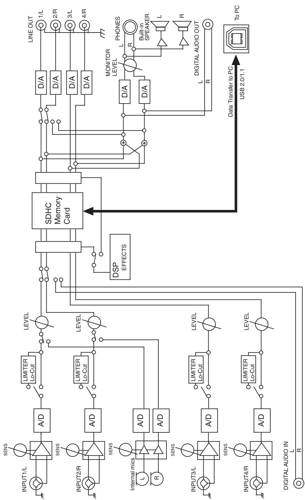
Numerics
3-Band EQ 58
4CH 23
4-indiv 41,69
A
A-B REPEAT 11,47
A-B Repeat Button 11
AC Adaptor 8,24
AC Adaptor Jack 14
Adjusting the input levels 30
Int-Mic 32
LEVEL 30
SENS 30
Alkaline 25,69
Amplified speakers 41
Analog 66
Analog device 41
B
Batteries 25
Battery Compartment 17
Battery life 26
Battery Low 74
Battery Time 69
Block diagram 81
Bottom panel 17
Bright 69
BUF 21
BWF 23
C
Channel level meters 18
Channel level sliders 19
Channel names 18
Check 70
CLEAR 11
Clear button 11
Clip level indicators 18-19
Combo Input Jacks 16
Comp&DeEsser 59
Computer 71
Control Sync Connector 14, 73
Copy 50
CTRLSYNC 14
Cursor Buttons 11
D
Date 68
Date & Time (Date and time) 19,62,70
DCIN 14
Delete 52
Dig + Ana 66
Digital 66
Digital device 33
DIGITAL IN 14
Digital Input Jack 14
DIGITAL OUT 14
Digital Output Jack 14
DISP 13
Display 13, 18, 20
DisplayButton 13
Display Setup 69
Display Timer 69
E
Effect Button 11
EFFECTS 11
Effects 55-56
Enhancer 59
ENTER/FINDER 12
Enter/Finder Button 12
EXIT 11
Exit Button 11
Extension pjt 22-23 wav 22-23
External power sources 27
Ext-Power 69
F
Factory Reset 65, 70
File size 23
File-Sys Error 74
Format 64, 70
Four-channel projects 23
Front panel 13
G
Graphic EQ 58
Grounding Terminal 15
H
Headphone Jack 13
Headphones 41
HOLD 10
HOLD ON 74
Hold Switch 10
1
Improper Proj. 74
Input Level 30
Input level knobs 13, 32, 35-36
Input level select switch 35-36
Input Select 66
Int + Ana 66
Int-Batt Low 74
Internal Mics 9
Internal Speakers 9
Int-Mic 66
L
LEN 18
LEVEL 13, 30
Level scale 18
LIMITER 10
Limiter 29,34,36
Limiter link 68
Limiter Switch 10
LINE OUT 15
Line Output Jacks 15
LOW CUT 10
Low Cut Switch 10
M
Macintosh 72
Main screen 18, 20
Make Folder 53
MARK 11,46
Mark button 11
Marker Buttons 11
Marker indicators 19
MEMORY CARD SLOT 14
MENU 11
Menu Button 11
MIC-L 9
MIC-R 9
Mixer screen 19
Monaural projects 22
monitor 41, 69
MONITOR (PUSH) SELECT 13
Monitor Level Knob 13
MONOx1 22
MONOx2 22
MONOx3 22
MONOx4 22
Move 51
MS-Mic 59
N
Name 68,74
Name too long 74
NEXT 12
NEXTButton 12
Nickel metal-hydride 25
Ni-MH 69
Noise Gate 58
Now Playing 74
Now Recording 74
0
Output assignments 18
Output level meters 19
Output Sel 69
Overprj#999 74
P
PAUSE 13
Pause Button 13
PHANTOM POWER 10
Phantom power switch 10, 29, 32-34, 36, 38-39
PHONES 13
pjt 22-23
PLAY 12
Play Button 12
Play Mode 43,68
Player Setup 43,68
POWER 11,24
Power source 19
Power Switch 11
Pre Recording 68
PREV 12
PREVButton 12
Progress bar 18
Project exists 74
Project Name 18,63,68,70
Projects 22
R
REC 13
Rec Bit 66
Rec Freq. 66
Rec Mode 67
Record button 13, 31-33, 35, 37
Recordable time 20
Recording Setup 61
Recording-standby 31
REM 19
Remaining space on SD memory card 20
Remaining time 19
Rename 49
Repair 54
Repeat 43,68
Rubber Flap 14
s
Sample size 18
Sampling frequency 18
Scrub dial 11
SCRUB/VALUE 11
SD buffering 74
SD Card 64, 70
SD Card Error 74
SD Card Full! 74
SD Card Locked 74
SD Card Slow! 74, 76
SD Unformatted 74
Security Slot 14
Select 48
SENS 13, 30
Sensitivity 30
Sequential 43,68
Side panel 14, 16
Single 43,68
Speaker 44,69
Speaker Switch 44,69
Stereo 23
Stereo projects 23
STOP 13
Stop Button 13
System settings 29,32-34,36,60
System Setup 69
T
Time counter 18, 20
Top panel 9
Total recording time 20
Total time 18
U
USB 14
USB Cable 8
USB connector 14
W
wav 22-23
WAV file 22-23
Windows 72
R-44 4-Channel Monitoring Chart
Format: MONOx4
Format: 4CHx1
Format: STEREO x 2
| Channel names | Output Assign-ment | Output Jack | Output Select (Type) | |
| 4-indiv | Monitor | |||
| 1L | L | 1/L | Mic 1 | Mic 1+3 |
| 1R | R | 2/R | Mic 2 | Mic 2+4 |
| 2L | L | 3/L | Mic 3 | Mic 3 |
| 2R | R | 4/R | Mic 4 | Mic 4 |
| Headphone L | Mic 1+3 | Mic 1+3 | ||
| Headphone R | Mic 2+4 | Mic 2+4 | ||
| 1L | L | 1/L | Mic 1 | Mic 1 |
| 1R | R | 2/R | Mic 2 | Mic 2 |
| 2L | L | 3/L | Mic 3 | Mic 3 |
| 2R | R | 4/R | Mic 4 | Mic 4 |
| Headphone L | Mic 1 | Mic 1 | ||
| Headphone R | Mic 2 | Mic 2 | ||
| 1L | L | 1/L | Mic 1 | Mic 3 |
| 1R | L | 2/R | Mic 2 | Mic 4 |
| 2L | L | 3/L | Mic 3 | Mic 3 |
| 2R | R | 4/R | Mic 4 | Mic 4 |
| Headphone L | Mic 3 | Mic 3 | ||
| Headphone R | Mic 4 | Mic 4 | ||
| 1L | LR | 1/L | Mic 1 | Mic 1+3 |
| 1R | LR | 2/R | Mic 2 | Mic 2+4 |
| 2L | LR | 3/L | Mic 3 | Mic 3 |
| 2R | LR | 4/R | Mic 4 | Mic 4 |
| Headphone L | Mic 1+2+3+4 | Mic 1+2+3+4 | ||
| Headphone R | Mic 1+2+3+4 | Mic 1+2+3+4 | ||
| 1L | LR | 1/L | Mic 1 | Mic 1 |
| 1R | L | 2/R | Mic 2 | Mic 1 |
| 2L | L | 3/L | Mic 3 | Mic 3 |
| 2R | L | 4/R | Mic 4 | Mic 4 |
| Headphone L | Mic 1 | Mic 1 | ||
| Headphone R | Mic 1 | Mic 1 | ||
| 1L | L | 1/L | Mic 1 | Mic 1 |
| 1R | LR | 2/R | Mic 2 | Mic 2 |
| 2L | L | 3/L | Mic 3 | Mic 3 |
| 2R | L | 4/R | Mic 4 | Mic 4 |
| Headphone L | Mic 2 | Mic 2 | ||
| Headphone R | Mic 2 | Mic 2 | ||
| 1L | L | 1/L | Mic 1 | Mic 3 |
| 1R | L | 2/R | Mic 2 | Mic 3 |
| 2L | LR | 3/L | Mic 3 | Mic 3 |
| 2R | L | 4/R | Mic 4 | Mic 4 |
| Headphone L | Mic 3 | Mic 3 | ||
| Headphone R | Mic 3 | Mic 3 | ||
| 1L | L | 1/L | Mic 1 | Mic 4 |
| 1R | L | 2/R | Mic 2 | Mic 4 |
| 2L | L | 3/L | Mic 3 | Mic 3 |
| 2R | L | 4/R | Mic 4 | Mic 4 |
| Headphone L | Mic 4 | Mic 4 | ||
| Headphone R | Mic 4 | Mic 4 | ||
| 1L | L | 1/L | Mic 1 | None |
| 1R | L | 2/R | Mic 2 | None |
| 2L | L | 3/L | Mic 3 | Mic 3 |
| 2R | L | 4/R | Mic 4 | Mic 4 |
| Headphone L | None | None | ||
| Headphone R | None | None | ||
| Channel names | Output Assign-ment | Output Jack | Output Select (Type) | |
| 4-indiv | Monitor | |||
| 1L | L | 1/L | Mic 1 | Mic 1+3 |
| 1R | R | 2/R | Mic 2 | Mic 2+4 |
| 2L | L | 3/L | Mic 3 | Mic 3 |
| 2R | R | 4/R | Mic 4 | Mic 4 |
| Headphone L | Mic 1+3 | Mic 1+3 | ||
| Headphone R | Mic 2+4 | Mic 2+4 | ||
| 1L | L | 1/L | Mic 1 | Mic 1 |
| 1R | R | 2/R | Mic 2 | Mic 2 |
| 2L | 3/L | Mic 3 | Mic 3 | |
| 2R | 4/R | Mic 4 | Mic 4 | |
| Headphone L | Mic 1 | Mic 1 | ||
| Headphone R | Mic 2 | Mic 2 | ||
| 1L | 1/L | Mic 1 | Mic 3 | |
| 1R | 2/R | Mic 2 | Mic 4 | |
| 2L | L | 3/L | Mic 3 | Mic 3 |
| 2R | R | 4/R | Mic 4 | Mic 4 |
| Headphone L | Mic 3 | Mic 3 | ||
| Headphone R | Mic 4 | Mic 4 | ||
| 1L | LR | 1/L | Mic 1 | Mic 1+2+3+4 |
| 1R | LR | 2/R | Mic 2 | Mic 1+2+3+4 |
| 2L | LR | 3/L | Mic 3 | Mic 3 |
| 2R | LR | 4/R | Mic 4 | Mic 4 |
| Headphone L | Mic 1+2+3+4 | Mic 1+2+3+4 | ||
| Headphone R | Mic 1+2+3+4 | Mic 1+2+3+4 | ||
| 1L | LR | 1/L | Mic 1 | Mic 1 |
| 1R | 2/R | Mic 2 | Mic 1 | |
| 2L | 3/L | Mic 3 | Mic 3 | |
| 2R | 4/R | Mic 4 | Mic 4 | |
| Headphone L | Mic 1 | Mic 1 | ||
| Headphone R | Mic 1 | Mic 1 | ||
| 1L | 1/L | Mic 1 | Mic 2 | |
| 1R | LR | 2/R | Mic 2 | Mic 2 |
| 2L | 3/L | Mic 3 | Mic 3 | |
| 2R | 4/R | Mic 4 | Mic 4 | |
| Headphone L | Mic 2 | Mic 2 | ||
| Headphone R | Mic 2 | Mic 2 | ||
| 1L | 1/L | Mic 1 | Mic 3 | |
| 1R | 2/R | Mic 2 | Mic 3 | |
| 2L | LR | 3/L | Mic 3 | Mic 3 |
| 2R | 4/R | Mic 4 | Mic 4 | |
| Headphone L | Mic 3 | Mic 3 | ||
| Headphone R | Mic 3 | Mic 3 | ||
| 1L | 1/L | Mic 1 | Mic 4 | |
| 1R | 2/R | Mic 2 | Mic 4 | |
| 2L | 3/L | Mic 3 | Mic 3 | |
| 2R | LR | 4/R | Mic 4 | Mic 4 |
| Headphone L | Mic 4 | Mic 4 | ||
| Headphone R | Mic 4 | Mic 4 | ||
| 1L | 1/L | Mic 1 | None | |
| 1R | 2/R | Mic 2 | None | |
| 2L | 3/L | Mic 3 | Mic 3 | |
| 2R | 4/R | Mic 4 | Mic 4 | |
| Headphone L | None | None | ||
| Headphone R | None | None | ||
| Chan- nel names | Output Assign- ment | Output Jack | Output Select (Type) | |
| 4-indiv | Monitor | |||
| 1L | L | 1/L | Mic 1 | Mic 1+3 |
| 1R | R | 2/R | Mic 2 | Mic 2+4 |
| 2L | L | 3/L | Mic 3 | Mic 3 |
| 2R | R | 4/R | Mic 4 | Mic 4 |
| Headphone L | Mic 1+3 | Mic 1+3 | ||
| Headphone R | Mic 2+4 | Mic 2+4 | ||
| 1L | L | 1/L | Mic 1 | Mic 1 |
| 1R | R | 2/R | Mic 2 | Mic 2 |
| 2L | 3/L | Mic 3 | Mic 3 | |
| 2R | 4/R | Mic 4 | Mic 4 | |
| Headphone L | Mic 1 | Mic 1 | ||
| Headphone R | Mic 2 | Mic 2 | ||
| 1L | 1/L | Mic 1 | Mic 3 | |
| 1R | 2/R | Mic 2 | Mic 4 | |
| 2L | L | 3/L | Mic 3 | Mic 3 |
| 2R | R | 4/R | Mic 4 | Mic 4 |
| Headphone L | Mic 3 | Mic 3 | ||
| Headphone R | Mic 4 | Mic 4 | ||
| 1L | LR | 1/L | Mic 1 | Mic 1+2+3+4 |
| 1R | LR | 2/R | Mic 2 | Mic 1+2+3+4 |
| 2L | LR | 3/L | Mic 3 | Mic 3 |
| 2R | LR | 4/R | Mic 4 | Mic 4 |
| Headphone L | Mic 1+2 | Mic 1+2+3+4 | ||
| Headphone R | Mic 1+2+3+4 | Mic 1+2+3+4 | ||
| 1L | LR | 1/L | Mic 1 | Mic 1 |
| 1R | 2/R | Mic 2 | Mic 1 | |
| 2L | 3/L | Mic 3 | Mic 3 | |
| 2R | 4/R | Mic 4 | Mic 4 | |
| Headphone L | Mic 1+2 | Mic 1 | ||
| Headphone R | Mic 1+2 | Mic 1 | ||
| 1L | 1/L | Mic 1 | Mic 2 | |
| 1R | LR | 2/R | Mic 2 | Mic 2 |
| 2L | 3/L | Mic 3 | Mic 3 | |
| 2R | 4/R | Mic 4 | Mic 4 | |
| Headphone L | Mic 2 | Mic 2 | ||
| Headphone R | Mic 2 | Mic 2 | ||
| 1L | 1/L | Mic 1 | Mic 3 | |
| 1R | 2/R | Mic 2 | Mic 3 | |
| 2L | LR | 3/L | Mic 3 | Mic 3 |
| 2R | 4/R | Mic 4 | Mic 4 | |
| Headphone L | Mic 3 | Mic 3 | ||
| Headphone R | Mic 3 | Mic 3 | ||
| 1L | 1/L | Mic 1 | Mic 4 | |
| 1R | 2/R | Mic 2 | Mic 4 | |
| 2L | 3/L | Mic 3 | Mic 3 | |
| 2R | LR | 4/R | Mic 4 | Mic 4 |
| Headphone L | Mic 4 | Mic 4 | ||
| Headphone R | Mic 4 | Mic 4 | ||
| 1L | 1/L | Mic 1 | None | |
| 1R | 2/R | Mic 2 | None | |
| 2L | 3/L | Mic 3 | Mic 3 | |
| 2R | 4/R | Mic 4 | Mic 4 | |
| Headphone L | None | None | ||
| Headphone R | None | None | ||
- Channel names (p. 18)
- Output Assignment (p. 18)
For EU Countries

This symbol indicates that in EU countries, this product must be collected separately from household waste, as defined in each region. Products bearing this symbol must not be discarded together with household waste.
DE Dieses Symbol beweet, dass这点 Product in EU-Ländern getrennt vom Hausmull gesammelt werden muss gemäß den regionalen Bestimmungen. Mit这点em Symbol gekennzeichnete Produkte dürfen nicht zusammen mit den Hausmull entsorgt werden.
FR Ce symbole indique que dans les pays de l'Union européenne, ce produit doit être collecté séparément des ordures menagères selon les directives en vigueur dans chacun de ces pays. Les produits portant ce symbole ne doivent pas été mis au rebut avec les ordures menagères.
Questo significato indica che nei paesi della Comunità europea questo prodotto devese essere smaltito separatamente dai normali rifiuti domestici, seconda la legalazione in vigore in ciascun paese. I prodotti che riportanoQuesto significato non devono essere smaltiti insieme ai rifiuti domestici. Ai sensi dell'art. 13 del D.Lgs. 25 luglio 2005 n. 151.
Es Este symbolo indica que en los paises de la Unión Europea this producto debe recogerse aparte de los residuos domesticos, tal como este regulado en cada zona. Los productos con este symbolo no se deben depositar con los residuos domesticos.
Estesbolo indica que nos paises da UE, a recolha deeste produits devera se feita separamente do lixo domestico,de acordo com os regulamentos de cada regia. Os produits que aparecem thissymbolo não devarao ser eliminados juntamente com o lixo domestico.
NL Dit symbool geeft aan dat in landen van de EU dit product geschieren van huishoudelijk afval moet worden aangeboden, zoals bepaal per gemeente of regio. Producten die van dit symbool zichoorzien, mogen Niet samen met huishoudelijk afval worden verwijderd.
Dette symbol angiver, at i EU-lande skal dette produit opsamples adskilt fra husholdningsaffald, som defineret i haverenkelt region. Produktier med dette symbol maiks smides udammen med hushholdningsaffald.
Dette symbolet indikerer at produit t ma behandles som spesialavfall i EU-land, iht. til retningsinjer for den enkelte regionen, og ici kastes sammen med vanlig husholdningsavfall. Produktor som er merket med dette symbolet, ma ici kastes sammen med vanlig husholdningsavfall.
SE Symbolen anger att i EU-länder maste den har Produkten kasseras separat fran hushallsavfall, i enliget med varje regions bestammelser. Produktker med den har symbolen farr inte kasseras tillsammans med hushallsavfall.
Täm merkinta ilmaisee,ettu tuote on EU-maisa kerattäv erilläan kotitalousjatteist kunkin alueen voimassa olevien märäysten mukaisesti. Talla merkinnallar varustettuja tuotteita ei saa havittaa kotitalousjatteiden mukana.
Ez a szimbólum azt jalenti, hogy az Europai Unióban EZT a terméket a háztartásii hulladěkól elkūlóníte, az adott régiónan érvényes szabályozás lásirint kellyüjteni. AZ ezzel a szimbóllum allatott termékekem nem szabad a háztartásii hulladěk kóze dobni.
Symbol oznacza, ze zgodnie z regulacjami w odpowiednim regionie, w krajach UE produktu nie nalezy wyrzucac z odpadami domowymi. Produktów opatrzych tym symbolem nie mayna utlylizowac razem z odpadami domowymi.
Tento symbol udává, Že v zemich EU músi ybt tento vyrobek shbrán odělené od domacího odadpu, jak je urceno pro kázdy region. Vyrobky nesoucī tento symbol se nésmí vyhazovat spolu s domacím odapadem.
SK Tento symbol vyjadruje, ze v krajinach EU sa musi zber tohto produktu vykonavat oddelene od domoveho oppadu, podfa nariadeni platn'yh v konkrtenej krajine. Produktys tymto symbolom sa nesmú vyhadzovat spolu s domovym opadom.
See sümól năṭab, et EL-i maades tuleb see toode olemprügist eraldi koguda, nii nagu on igas piirkonnas märarletud. Selle sümboliga margitud totoed i tehi āra visata koos olmeprügia.
LT Sis simbolis rodo, kad ES salyse sis produktas turi buti surenkamas atskirai nuo buitiniu atleku, kaip nustatyta kiekviename regione. Suo simuloliu pazenklinti produktai neturi buti ismetami kartu su buitinemis atliekomis.
Sis.simbols norada, ka ES valstis so produktu jaievac atseviški no māsjaimmiečbas atkrititumemi, kā noteikts katra regiona. Produktus ar so simulbu nedrftskizmestkopar māsjaimmiečbas atkrititumemi.
Ta symbol označuje, da je treba proizvod v državah EU zbirati ločeno od gospodinjskij odpadkov, kato kot je doloceno v vsaki regiji. Proizvoda s tem znakom ni dovoljeno odlagat su kajp z gospodinjskimi odpadki.
To oufo auto vto odnojovoi otoux ooec ts E.E. to ovvexoevo noioov npentai va ouuyetyo xyoqotarao ta utolouta ouuaia aotogmuata, oivpoova me ooa pboiEvovatae naoe neooyi. Ta ovoiota nov feogov to ovvexoevo oipolo evnpieta va atooqitovtanaucu ma tae onaaia aotogmuatta.
For China
有关产品中所含有害物质的说明
IMPORTANT: THE WIRES IN THIS MAINS LEAD ARE COLOURED IN ACCORDANCE WITH THE FOLLOWING CODE.
BLUE: NEUTRAL
BROWN: LIVE
As the colours of the wires in the mains lead of this apparatus may not correspond with the coloured markings identifying the terminals in your plug, proceed as follows:
The wire which is coloured BLUE must be connected to the terminal which is marked with the letter N or coloured BLACK. The wire which is coloured BROWN must be connected to the terminal which is marked with the letter L or coloured RED.
Under no circumstances must either of the above wires be connected to the earth terminal of a three pin plug.
For C.A. US (Proposition 65)
WARNING
This product contains chemicals known to cause cancer, birth defects and other reproductive harm, including lead.
For the USA
DECLARATION OF CONFORMITY Compliance Information Statement
Model Name: R-44
Type of Equipment : 4- CHANNEL PORTABLE REORDER and WAVE EDITOR
Responsible Party: Roland Systems Group U.S.
Address: 425 Sequoia Drive Suite 114, Bellingham, Washington, 98226 USA
Telephone: 360-594-4282
- Microsoft and Windows are registered trademarks of Microsoft Corporation.
- Windows® is known officially as: "Microsoft® Windows® operating system."
- Apple and Macintosh are registered trademarks of Apple Inc.
- Mac OS is a trademark of Apple Inc.
- All product names mentioned in this document are trademarks or registered trademarks of their respective owners.
- SDHC Logo is a trademark

- Fugue © 2008 Kyoto Software Research, Inc. All rights reserved.
Information
When you need repair service, call your nearest EDIROL/Roland Service Center or authorized EDIROL/Roland distributor in your country as shown below.
ASIA
INDONESIA
PT. Citra IntiRama
5F.No.1500 Pingliang Road
Shanghai 200090, CHINA
TEL: (021) 5580-0800
Roland Shanghai Electronics Co., Ltd.
(BEIJING OFFICE)
10F. No.18 3 Section Anhuaxili
Chaoyang District Beijing
100011 CHINA
TEL: (010) 6426-5050
KOREA
KOREA AVICS CO., LTD.
463-3 Sunghwa bldg. 3rd F.,
Seokyo-Dong, Mapo-ku,
Seoul, KOREA
Tel: 02-322-3264
TAIWAN
ROLAND TAIWAN
ENTERPRISE CO.,LTD.
Room 5, 9fl. No. 112 Chung Shan
N.Road Sec.2, Taipei, TAIWAN.
R.O.C.
TEL: (02) 2561 3339
SINGAPORE/
MALAYSIA
Roland Asia Pacific Sdn. Bhd.
45-1, Block C2, Jalan PJU 1/39
Dataran Prima, 47301 Petaling
Jaya, Selangor, MALAYSIA
TEL: 3-7805-3263
CENTRAL/LATIN AMERICA
BRAZIL
Roland Brasil Ltda.
Rua San Jose, 780 Sala B
Parque Industrial San Jose
Cotia - Sao Paulo - SP, BRAZIL
TEL: (011) 4615 5666
Other CENTRAL/LATIN LAMERICA
Roland Systems Group U.S.
425 Sequoia Drive Suite 114
Bellingham, Washington.
98226 USA
TEL: 360-594-4282
EUROPE
AUSTRIA/GERMANY/ITALY/IRELAND/UNITED KINGDOM
EDIROL (Europe) Ltd.
Studio 3.4 114 Power Road
London W4 5PY
U.K
TEL: (0)20 8747 5949
BELGIUM/FRANCE/LUXEMBOURG/SWITZERLAND/
HOLLAND/SPAIN/ PORTUGAL
Roland Iberia, S.L.
Paseo Garcia Faria, 33-35
08005 Barcelona SPAIN
TEL: 934939100
CROATIA
ART-CENTAR
Degenova 3.
HR - 10000 Zagreb
TEL: (1) 466 8493
CZECH REP.
CZECH REPUBLIC
DISTRIBUTORS.r.o
Voctarova 247/16
CZ-180 00 PRAHA 8,
CZECH REP.
TEL: (2) 830 20270
DENMARK
Roland Scandinavia A/S
Nordhavnsvej 7, Postbox 880,
DK-2100 Copenhagen
DENMARK
TEL:39166200
FINLAND
Roland Scandinavia As,
Filial Finland
Elannontie 5
FIN-01510 Vantaa, FINLAND
TEL: (0)968 24 020
NORWAY
Roland Scandinavia Avd.
Kontor Norge
Danvik Center 28, 2 tr
S-131 30 Nacka SWEDEN
TEL: (0)8702 00 20
HUNGARY
Roland East Europe Ltd.
Warehouse Area DEPO' Pf.83
H-2046 Torokbalint, HUNGARY
TEL: (23) 511011
POLAND
ROLAND POLSKA SP. Z O.O.
UL.Gibraltarska 4.
PL-03 664 Warszawa
POLAND
TEL: (022) 679 4419
ROMANIA
FBS LINES
Piata Libertatii 1,
535500 Gheorgheni, ROMANIA
TEL: (266) 364 609
RUSSIA
MuTek
Dorozhnava ul.3.korp.6
117 545 Moscow, RUSSIA
TEL: (095) 981-4967
SLOVAKIA
DAN Acoustic s.r.o.
Povazská 18.
SK-940 01 Nové Zámky
TEL: (035) 6424 330
UKRAINE
EURHYTHMICS Ltd.
P.O.Box:37-a
Nedecey Str. 30
UA - 89600 Mukachevo,
UKRAINE
TEL: (03131) 414-40
OCEANIA
Roland Corporation
Australia Pty., Ltd.
38 Campbell Avenue
Dee Why West, NSW 2099
AUSTRALIA
For Australia
Tel: (02) 9982 8266
For New Zealand
Tel: (09) 3098 715
NORTH AMERICA
CANADA
Roland Canada Ltd.
(Head Office)
5480 Parkwood Way, Richmond
B.C.,V6V2M4CANADA
TEL: (604) 270 6626
Roland Canada Ltd.
(Toronto Office)
170 Admiral Boulevard
Mississauga ON L5T 2N6
CANADA
TEL: (905) 362 9707
U.S.A.
Roland Systems Group U.S.
425 Sequoia Drive Suite 114,
Bellingham, Washington,
98226 USA
TEL: 360-594-4282