
TVAC14010A - Surveillance Camera ABUS - Free user manual and instructions
Find the device manual for free TVAC14010A ABUS in PDF.


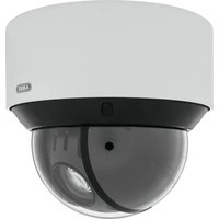
| Product Type | Surveillance Camera |
| Brand | ABUS |
| Model | TVAC14010A |
| Dimensions (L x W x H) | 7.0 x 9.0 x 12.0 cm |
| Weight | 300 g |
| Power Supply | 12 V DC / PoE (Power over Ethernet) |
| Resolution | Full HD 1080p (1920 x 1080 pixels) |
| Viewing Angle | 90° (diagonal) |
| Night Vision | Yes, up to 30 meters (infrared LEDs) |
| Motion Detection | Yes, with push notification |
| Connectivity | Ethernet RJ45, Wi-Fi (optional) |
| Storage | microSD card (up to 128 GB) or NAS |
| Protection | IP66 rating (weatherproof) |
| Operating Temperature | -20°C to +50°C |
| Maintenance and Cleaning | Clean with a soft, dry cloth. Do not use harsh chemicals. |
| Security | Data encryption (HTTPS, AES) |
| Spare Parts and Repairability | Power cable, power adapter, mounting bracket. Repair by ABUS authorized service. |
| General Information | 2-year warranty. Compatible with ABUS video surveillance systems. |
Frequently Asked Questions - TVAC14010A ABUS
User questions about TVAC14010A ABUS
0 question about this device. Answer the ones you know or ask your own.
Ask a new question about this device
Download the instructions for your Surveillance Camera in PDF format for free! Find your manual TVAC14010A - ABUS and take your electronic device back in hand. On this page are published all the documents necessary for the use of your device. TVAC14010A by ABUS.
USER MANUAL TVAC14010A ABUS
natural_image
Black USB security camera with antenna and control panel (no visible text or symbols)D Bedienungsanleitung
UK User guide
© Notice d'utilisation
NL Gebruikershandleiding
① Istruzioni per l'uso
This user guide contains important information on starting operation and using the device.
Make sure that this user guide is handed over when the product is given to other persons.
Keep this user guide to consult later.
A list of contents with the corresponding page number can be found in the index on page 19.
Français
natural_image
Black ARUS 3D camera with visible sensor interface and antenna (no text or symbols on body)Bedienungsanleitung
| 1 | Antenne |
| 2 | IR-LEDs |
| 3 | Power LED |
| 4 | Kamerahalterung |
| 5 | Fix-Objektiv |
| 6 | Link LED |

natural_image
Line drawing of a mechanical device with a hand pointing to a labeled connector (no text or symbols present)natural_image
Technical line drawing of a mechanical assembly with screwdriver and tool, no text or symbols presentnatural_image
Technical line drawing of a mechanical device with a cylindrical component and attached bracket (no text or symbols)natural_image
Black wireless camera with antenna and control panel (no visible text or symbols)User manual
You can find important information and FAQs about this and other products online at:
Thank you for purchasing this product.
This device complies with the requirements of the applicable EU directives. The declaration of conformity can be obtained from:
To ensure this condition is maintained and that safe operation is guaranteed, it is your obligation to observe this user manual.
Read the entire user manual carefully before putting the product into operation, and pay attention to all operating instructions and safety information.
All company names and product descriptions are trademarks of the corresponding owner. All rights reserved.
If you have any questions, please contact your specialist installation contractor or specialist dealer.

Data storage is subject to national data privacy guidelines.

Warning as required by §201 StGB (German Criminal Code):
Whosoever unlawfully makes an audio recording of the privately spoken words of another, and uses or makes a recording thus produced accessible to a third party, shall be liable to imprisonment or a fine. Whosoever unlawfully overhears with an eavesdropping device the privately spoken words of another not intended for his attention, or publicly communicates, verbatim or the essential content of, the privately spoken words of another, recorded or overheard, shall incur the same penalty.

Disclaimer
This user manual has been produced with the greatest of care. Should you discover any omissions or inaccuracies, please contact us in writing under the address provided above.
ABUS Security-Center GmbH does not accept any liability for technical and typographical errors, and reserves the right to make changes to the product and user manuals at any time and without prior warning.
ABUS Security-Center GmbH is not liable or responsible for direct or indirect damage resulting from the equipment, performance and use of this product. No forms of guarantee are assumed for the contents of this document.
Explanation of symbols
 | The triangular high voltage symbol is used to warn of the risk of injury or health hazards (e.g. caused by electric shock). |
 | The triangular warning symbol indicates important notes in this user manual which must be observed. |
 | This symbol indicates special tips and notes on the operation of the unit. |
Important safety information
 | All guarantee claims are invalid in the event of damage caused by non-compliance with this user manual. We cannot be held liable for resulting damage. |
 | In the event of material or personal damage caused by improper operation or non-compliance with the safety information, we cannot be held liable. All guarantee claims are void in such cases. |
This device has been manufactured in accordance with international safety standards.
Please read the following safety instructions carefully.
Safety information
1. Power supply
Only operate the camera through a power source which supplies the mains power specified on the type plate. If you are unsure of the installation location's power supply, contact your power supply company. Disconnect the device from the power supply before carrying out maintenance or installation work.
2. Overloading
Avoid overloading electrical sockets, extension cables, and adapters, as this can result in fires or electric shocks.
3. Cleaning
Only use a damp cloth to clean the camera. Do not use corrosive cleaning materials.
Disconnect the monitor and camera from the power supply before cleaning.
4. Accessories
Only connect accessories that are expressly suitable for their intended purpose. Otherwise, hazardous situations or damage to the monitor or camera may occur.
5. Installation location
The camera is suitable both for operation in protected outdoor areas as well as indoors. The product may be damaged if it is dropped, even from a low height. Install the camera so that the image sensor is not exposed to direct sunlight. Pay attention to the installation instructions in the corresponding section of this user manual. Only operate the camera at locations where temperatures within the permitted ambient temperature range prevail.
Camera -10°\~ +50°C
6. Wireless transmission
The wireless transmission range depends on a variety of environmental factors. The local conditions at the installation location may have a negative impact on the range. When there are no obstructions between the receiver and transmitter, a range of up to 150 m is possible, but this range will be considerably smaller within buildings.
The following environmental conditions compromise both the range and frame rate:
mobile communication masts, high-tension pylons, electrical wires, ceilings and walls, devices with an identical or adjacent wireless frequency.
Warnings
Observe all safety and operating instructions before putting the device into operation for the first time.
-
Observe the following information to avoid damage to the power cable and plug:
-
Do not modify or manipulate the power cable or plug.
- Do not pull the cable when disconnecting the device from the power – always take hold of the plug.
-
Ensure that the power cable is positioned as far away as possible from any heating equipment, as this could otherwise melt the plastic coating.
-
Follow these instructions. Non-compliance with these instructions could lead to an electric shock:
-
Never open the housing or power supply unit.
- Do not insert any metallic or flammable objects into the device interior.
-
Use surge protection to prevent damage caused by overvoltages (e.g. in electrical storms).
-
Disconnect defective devices from the power immediately and contact your specialist dealer.

If in doubt, have a specialist technician carry out assembly, installation and connection of the device. Improper or unprofessional work on the power supply system or domestic installation puts both you and other persons at risk.
Connect the installations so that the mains power circuit and low-voltage circuit always run separately from each other. They should not be connected at any point or become connected as a result of a malfunction.
Avoid the following adverse conditions during operation:
- Moisture or excess humidity
• Temperatures outside the permitted range - Direct sunlight
• Dust or flammable gases, vapours or solvents
• Strong vibrations
• Strong magnetic fields (e.g. next to machines or loudspeakers)
Unpacking the device
Handle the device with extreme care when unpacking it.

If the original packaging has been damaged, you must start by inspecting the device. If the device shows signs of damage, return it in the original packaging and inform the delivery service.
Contents
- Intended use....20
- Scope of delivery.... 20
- Features and functions.... 20
- Camera description 21
- Installation 23
5.1. Pairing the camera and the monitor 23
5.2. Mounting the camera.... 23 - Maintenance and cleaning 25
6.1. Maintenance 25
6.2. Cleaning.... 25 - Disposal 25
- Technical data 26
1. Intended use
This IR 2.4 GHz wireless outdoor camera is an optional accessory for the 7" wireless monitor (TVAC14000A). You have the option to connect up to four cameras with the monitor. With this 2.4 GHz IR wireless outdoor camera, you can easily transmit video signals to the wireless monitor via wireless communication.
Wireless signal transmission is an advantage everywhere cables are not able to be laid: the camera transmits the video signal wirelessly to the monitor. The conversion to digital signals means that malfunctions and interference can be prevented.
2. Scope of delivery

Camera mount including mounting material

IR wireless outdoor camera
2.4 GHz

Antenna
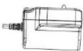

Power supply unit incl. EU and UK 5 V DC/1 A adapter
3. Features and functions
- Wireless outdoor camera for 7" home video surveillance set (TAVC14000A)
- Robust, weather-proof wireless outdoor cameras (IP66) with infrared night vision function and VGA resolution
• Recording via motion detection, following a time schedule or continuously - Up to four wireless cameras can be used with each home video surveillance set
4. Camera description
Front view:

| 1 | Antenna |
| 2 | IR LEDs |
| 3 | Power LED |
| 4 | Camera mount |
| 5 | Fixed lens |
| 6 | Link LED |
| LED | Status | Meaning |
| Power LED 3 | On (red) | Camera on |
| Off | Camera off | |
| Link LED 6 | Flashing | Camera is in the "pairing mode" |
| On (green) | Camera is connected to the monitor | |
| Off | Camera is in standby |
Back view:

| 1 | SMA connection |
| 2 | Microphone |
| 3 | Pairing button |
| 4 | Power supply connection |
5. Installation
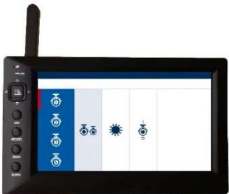
5.1. Pairing the camera and the monitor

natural_image
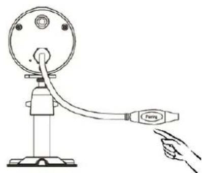
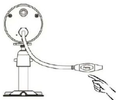
Line drawing of a hand operating a mechanical device with a connecting rod labeled 'Ferry' (no text or symbols on the device itself)To connect a camera with the monitor, proceed as follows:
- Connect the camera and the monitor to the power supply units.
- In the monitor menu, select "Camera settings", then the required camera. Now select the "Pair camera" option and press the menu button.
- Then press the PAIRING button on the camera cable. The green link LED starts to flash.
- Once the connection is established, the link LED on the camera illuminates for 2 seconds and then goes out. The message "Pairing successful" appears on the monitor.

Important:
Please note that the connection can take up to 60 seconds.
5.2. Mounting the camera
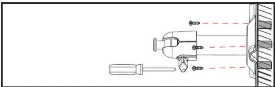
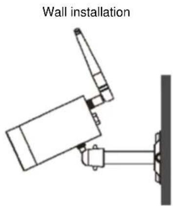
Use the camera mount to help you find a suitable installation location. Now mark the drill holes on the surface, and drill the holes. Insert the screw anchors supplied before you attach the mount with the screws.

Important:
Before you begin installing, make sure that the wireless transmission range is adequate at the site of the required installation.
To do this, first screw in the antenna supplied.
natural_image
Technical line drawing of a mechanical assembly with screwdriver and tool, no text or symbols presentYou can also swivel the mount by 90^ into a particular position. First loosen the screw on the side and set the required angle. Then tighten the screw to secure the required position.
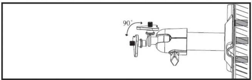
Then screw the camera onto the mount and connect the power supply unit with the camera.

natural_image
Technical line drawing of a mechanical device with a vertical rod and attached bracket (no text or symbols)Mounting options:

6. Maintenance and cleaning
6.1. Maintenance
Regularly check the technical safety of the product, e.g. check the housing for damage.
If it seems that it may no longer be possible to operate the device safely, stop using the product and secure it to prevent unintentional use.
It is likely that safe operation is no longer possible in the event that:
• the device shows signs of visible damage
- the device no longer works correctly.

Please note:
You do not need to perform any maintenance on the product. There are no components to service and nothing inside the product which requires verification. Never open it.
6.2. Cleaning
Clean the product with a clean, dry cloth. The cloth can be dampened with lukewarm water if there is dirt that is hard to remove.

Do not allow any liquids to enter the device.
Do not use any chemical cleaning products as they could damage the surface of the housing and screen (discolouration).
7. Disposal

Important: EU Directive 2002/96/EC regulates the proper return, treatment and recycling of used electronic devices. This symbol means that in the interest of environmental protection, the device must be disposed of separately from household or industrial waste at the end of its service life in accordance with applicable local legal guidelines. Used devices can be disposed of at official recycling centres in your country. Obey local regulations when disposing of material. Further details on returns (also for non-EU countries) can be obtained from your local authority. Separate collection and recycling conserves natural resources and ensures that all the provisions for protecting health and the environment are observed when recycling the product.
8. Technical data
| Model number TVAC14010A | |
| Resolution 640 x 480 pixels | |
| Image sensor 1/4" CMOS | |
| Lens | 3.6 mm (fixed lens) |
| Angle of view 60° (horizontal)/43° (vertical) | |
| Number of high-power IR LEDs 6 | |
| IR swivel filter Yes | |
| Range of night vision function | Max. 5 metres |
| Frequency 2.4 GHz | |
| Wireless range | 150 m* |
| Transmission power | 15 +/-2 dBm |
| Sensitivity -80 dBm | |
| Modulation FHSS | |
| IP protection class 66 | |
| Max. operating temperature -10°C to +50°C | |
| DC voltage supply | 5 V DC |
| Power consumption | 550 mA (max.) |
| Dimensions | 150 x 74 x 68 |
| Weight | 390 g |
| Certifications | CE |
* The range is dependent on environmental factors (e.g. mobile communication masts, high-tension pylons, electrical wires, ceilings and walls, etc.).
If conditions are not favourable, the range will be limited.
TVAC14010A

natural_image
Black USB security camera with antenna and control panel (no visible text or symbols)www.abus.com/fr/Securite-a-installer-soi-meme
6. Transmission radio

natural_image
Line drawing of a mechanical device with a hand pointing to a labeled connector (no text or symbols present)natural_image
Technical line drawing of a mechanical assembly with screwdriver and housing (no text or symbols)natural_image
Technical line drawing of a security camera mounted on a wall-mounted bracket (no text or symbols)natural_image
Black ARUS 3D camera with antenna and control panel (no visible text or symbols)| 1 | Antenne |
| 2 | IR-LED's |
| 3 | Power-LED |
| 4 | Camerasteun |
| 5 | Vast objectief |
| 6 | Link-LED |
natural_image
Line drawing of a mechanical device with a hand pointing to a labeled connector (no text or symbols present)natural_image
Technical line drawing of a mechanical assembly with screwdriver and tool, no text or symbols presentnatural_image
Technical line drawing of a mechanical device with attached bracket and vertical wall (no text or symbols)natural_image
Black ARUS 3D camera with visible sensor interface and antenna (no text or symbols on body)Telecamera -10°\~ +50 °C
6. Trasmissione radio
natural_image
Line drawing of a hand pulling a mechanical device labeled 'Ferry' from a stand (no text or symbols on the device itself)natural_image
Technical line drawing of a mechanical assembly with screwdriver and tool, no text or symbols presentnatural_image
Technical line drawing of a mechanical device with a vertical rod and attached bracket (no text or symbols)These operating instructions are published by ABUS Security-Center GmbH & Co.KG, Linker Kreuthweg 5, 86444 Affing, Germany. No reproduction (including translation) is permitted in whole or part e.g. photocopy, microfilming or storage in electronic data processing equipment, without the express written consent of the publisher.
The operating instructions reflect the current technical specifications at the time of print.
We reserve the right to change the technical or physical specifications.
- Bedienungsanleitung
- User manual
- Warning as required by §201 StGB (German Criminal Code):
- Disclaimer
- Safety information
- Power supply
- Overloading
- Cleaning
- Accessories
- Installation location
- Wireless transmission
- Warnings
- Unpacking the device
- Contents
- Intended use
- Scope of delivery
- Features and functions
- Camera description
- Installation
- Pairing the camera and the monitor
- Important:
- Mounting the camera
- Maintenance and cleaning
- Maintenance
- Cleaning
- Disposal
- Technical data
- TVAC14010A
- Transmission radio
- Trasmissione radio
Brand : ABUS
Model : TVAC14010A
Category : Surveillance Camera