
L04308004 - Range hood INDESIT - Free user manual and instructions
Find the device manual for free L04308004 INDESIT in PDF.
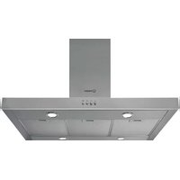
| Product type | Wall-mounted range hood |
| Brand | Indesit |
| Model | L04308004 (equivalent HIP6 IX / HIP9 IX) |
| Dimensions (W x H x D) | 59.8 x 68–119 x 49 cm (60 cm model) |
| Exhaust duct diameter | 150 mm |
| Gross weight | 16.8 kg (60 cm model) |
| Power supply | 230 V ~ 50 Hz |
| Total absorbed power | 215 W (60 cm model) |
| Motor power | 135 W |
| Lighting | 2 bulbs of 40 W max (type E14) |
| Max air flow | 430 m³/h |
| Grease filter suction surface | 1487 cm² |
| Number of speeds | 3 motor speeds + lighting |
| Controls | 4 push buttons (lighting, on/off, speeds 2 and 3) |
| Installation modes | Suction version (extraction) or filtering version (recirculation) |
| Grease filter | Washable metal (hand or dishwasher) |
| Charcoal filter (optional) | To be replaced every 6 months (for filtering version) |
| Maintenance | Exterior cleaning with a damp cloth and mild detergent; interior with denatured alcohol |
| Minimum distance to cooking surface | 65 cm (or more according to the hob instructions) |
| Insulation class | Class II (double insulation, no grounding) |
| Warranty and repairability | Spare parts available via Indesit after-sales service |
Frequently Asked Questions - L04308004 INDESIT
User questions about L04308004 INDESIT
0 question about this device. Answer the ones you know or ask your own.
Ask a new question about this device
Download the instructions for your Range hood in PDF format for free! Find your manual L04308004 - INDESIT and take your electronic device back in hand. On this page are published all the documents necessary for the use of your device. L04308004 by INDESIT.
USER MANUAL L04308004 INDESIT
Technical information, 12
Electrical connection
Technical data
Description, 13
Filtering version
Ducting version
Operation, 14
Controls
Maintenance,15
Cleaning the hood
Cleaning the grease filters
Replacing the charcoal filter
Replacing the lamps
Precautions and tips, 16
General safety
Air vent
Disposal
Assembly
Before proceeding with the assembly operations, remove the grease filters so that the hood is easier to handle (for the instructions see the paragraph "Cleaning the grease filters" in the chapter on "Maintenance").
Fixing to the wall
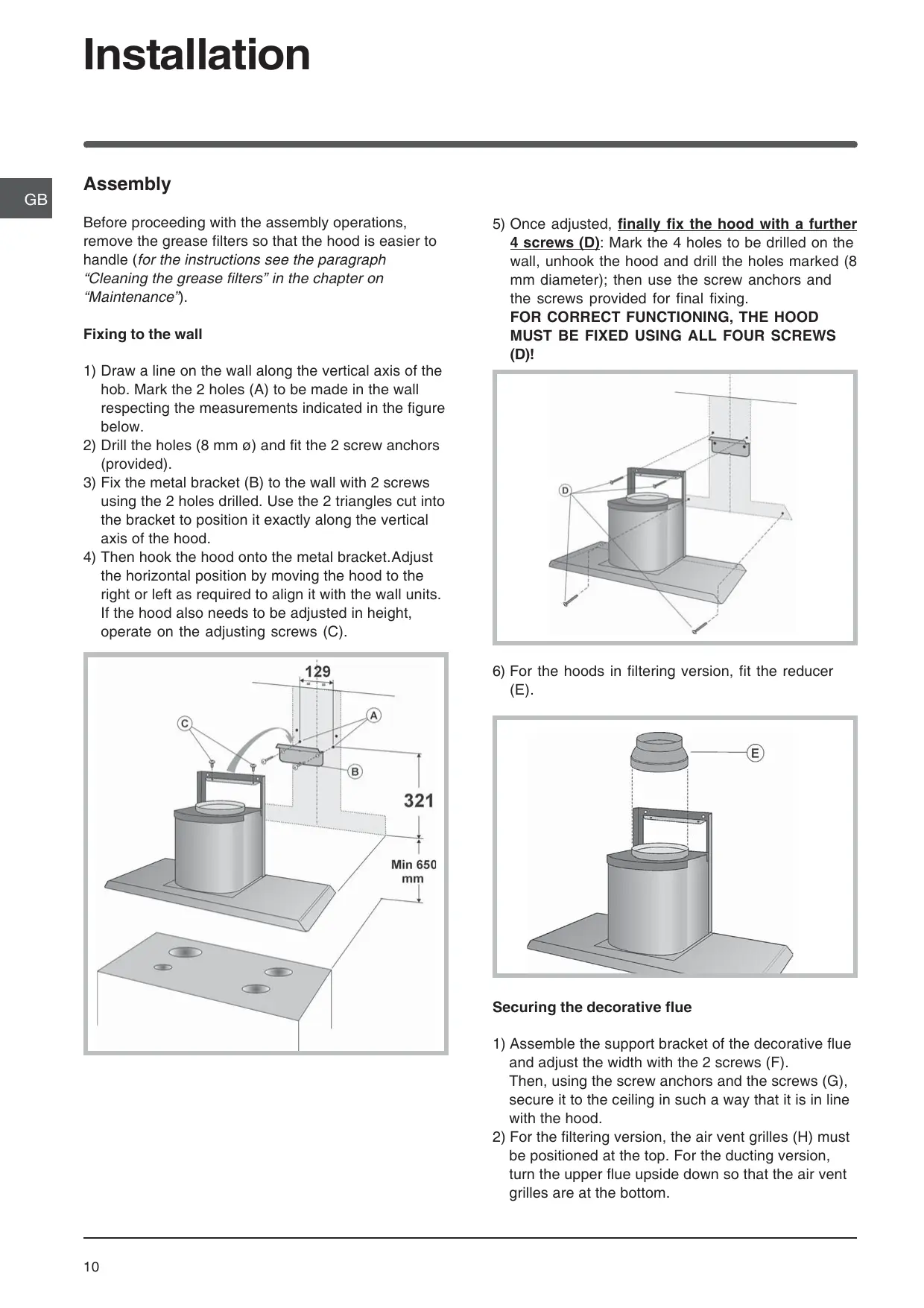
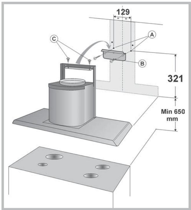
1) Draw a line on the wall along the vertical axis of the hob. Mark the 2 holes (A) to be made in the wall respecting the measurements indicated in the figure below.
2) Drill the holes (8 mm Ø) and fit the 2 screw anchors (provided).
3) Fix the metal bracket (B) to the wall with 2 screws using the 2 holes drilled. Use the 2 triangles cut into the bracket to position it exactly along the vertical axis of the hood.
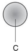
4) Then hook the hood onto the metal bracket. Adjust the horizontal position by moving the hood to the right or left as required to align it with the wall units. If the hood also needs to be adjusted in height, operate on the adjusting screws (C).
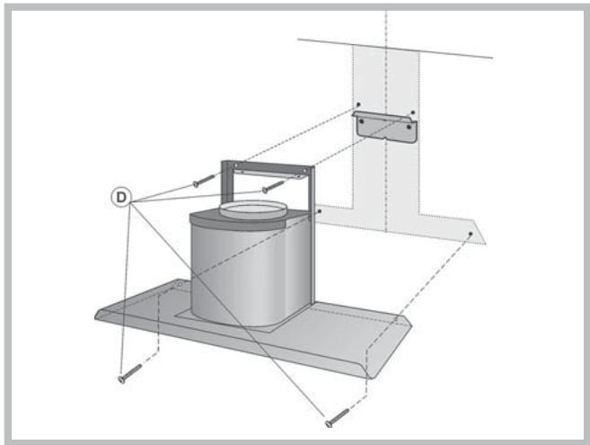
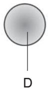
5) Once adjusted, finally fix the hood with a further 4 screws (D): Mark the 4 holes to be drilled on the wall, unhook the hood and drill the holes marked (8 mm diameter); then use the screw anchors and the screws provided for final fixing. FOR CORRECT FUNCTIONING, THE HOOD MUST BE FIXED USING ALL FOUR SCREWS (D)!
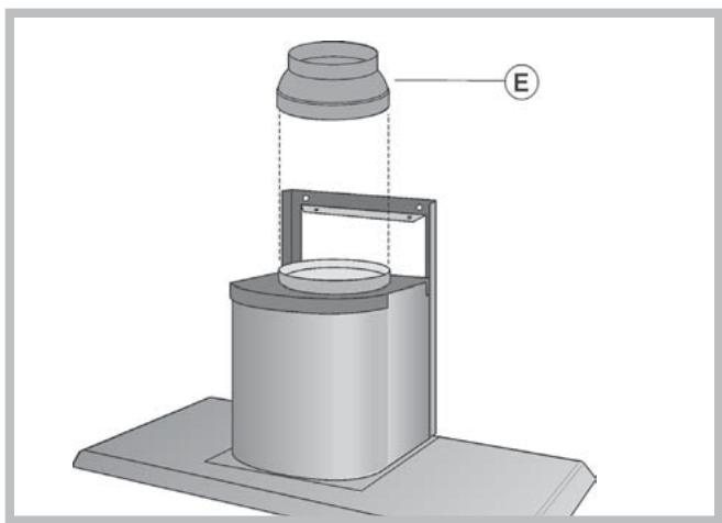
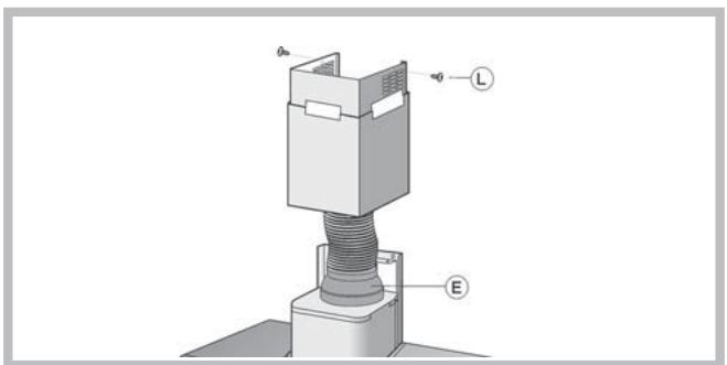
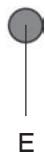
6) For the hoods in filtering version, fit the reducer (E).
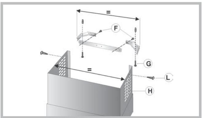
Securing the decorative flue
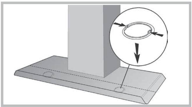
1) Assemble the support bracket of the decorative flue and adjust the width with the 2 screws (F).
Then, using the screw anchors and the screws (G), secure it to the ceiling in such a way that it is in line with the hood.
2) For the filtering version, the air vent grilles (H) must be positioned at the top. For the ducting version, turn the upper flue upside down so that the air vent grilles are at the bottom.
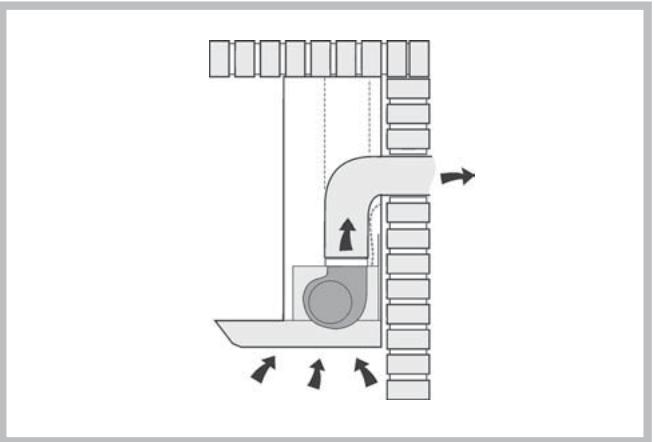
3) Ducting version:
a) Connect the air vent of the hood to the air vent hole using a flexible hose of 15cm diameter. Lock the flexible hose with hose clamps (hose and clamps not provided).
b) Make the electrical connection of the hood by means of the power cable (refer to the paragraph "Electrical connection").
c) Fit the decorative flue resting it on the hood. Lift the upper flue up to the ceiling and secure it by means of the 2 screws (L).
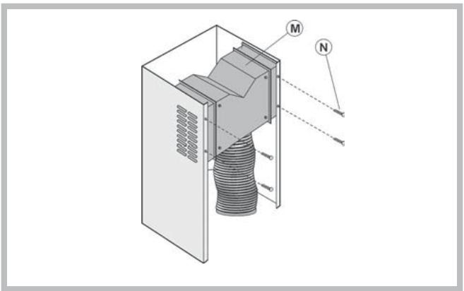
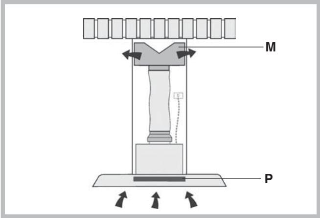
4) Filtering version:
a) Fit the baffle (M) to the upper flue using 4 flatheaded screws (N). Connect a flexible hose of 12.5cm diameter to the baffle locking it with a hose clamp (hose and clamp not provided).
b) Take the decorative flue and rest it on the hood. Lift the upper flue up to the ceiling and secure it using the 2 screws (L).
c) Lift the lower flue holding it firm with some adhesive tape and connect the flexible hose to the reducer (E) with a hose clamp (not provided).
d) Make the electrical connection of the hood by means of the power cable (refer to the paragraph "Electrical connection").
e) Lower the lower flue resting it on the hood.
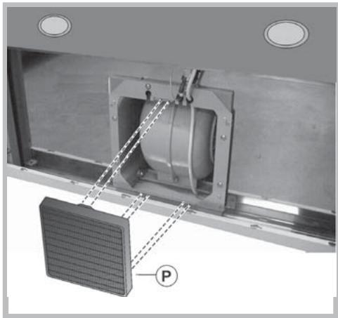
f) Check if the charcoal filter (P) has been installed. If not yet installed, proceed by sliding the 2 filter clips into their seats and turn the filter upwards.
Electrical connection
! Arrange the electrical power supply within the decorative flue dimensions.
! When making the electrical connections, check that the voltage values correspond to those indicated on the data plate inside the appliance itself.
! In case your appliance is not furnished with a non separating flexible cable and has no plug, or has not got any other device ensuring omnipolar disconnection from the electricity main, with a contact opening distance of at least 3mm , such separating device ensuring disconnection from the main must be included in the fixed installation.
If your unit features a power lead and plug, position this so the plug is accessible.
Technical data
| Model | HIP6 IX / HIP6 F IX | HIP9 IX / HIP9 F IX |
| Dimensions | width 59.8 cm | width 89.8 cm |
| height 68/119 cm | height 68/119 cm | |
| depth 49 cm | depth 49 cm | |
| Outlet pipe diameter 15 cm | Outlet pipe diameter 15 cm | |
| Gross weight | 16.8 Kg | 17.9 Kg |
| Absorption | Total 215 W | Total 215 W |
| Motor 1x135 W | Motor 1x135 W | |
| Lamps 2x40 W | Lamps 2x40 W | |
| Flow rate | 430 m³/h | 430 m³/h |
| Grease filters | ||
| Suction | ||
| surface area | 1487 cm² | 2287 cm² |
| Model | HIP6 P IX | HIP9 P IX |
| Dimensions | width 59.8 cm | width 89.8 cm |
| height 68/119 cm | height 68/119 cm | |
| depth 49 cm | depth 49 cm | |
| Outlet pipe diameter 15 cm | Outlet pipe diameter 15 cm | |
| Gross weight | 17.8 Kg | 18.9 Kg |
| Absorption | Total 270 W | Total 270 W |
| Motor 1x190 W | Motor 1x190 W | |
| Lamps 2x40 W | Lamps 2x40 W | |
| Flow rate | 585 m³/h | 585 m³/h |
| Grease filters | ||
| Suction | ||
| surface area | 1487 cm² | 2287 cm² |
The hood may be in the filtering or ducting version. Decide from the outset which type is to be installed. For better efficiency, we recommend installing the hood in the ducting version (if possible).
Filtering version
The hood aspirates air from the kitchen impregnated with fumes and smells, purifies it through the grease filters and the charcoal filter, and then circulates clean air back into the room.
This version requires an air baffle (M) and a charcoal filter (P).
In order to maintain constant efficiency, the charcoal filter must periodically be replaced.
If the hood is not fitted with the charcoal filter, request one from the dealer.
Ducting version
The hood aspirates air from the kitchen impregnated with fumes and smells, passes it through the grease filters and then expels it to the outside through an exhaust duct.
For this version the charcoal filter does not need to be used.
Controls
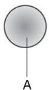
A - Light button
Turns the lights on/off.
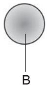
B - Motor ON/OFF button
Activates/deactivates the motor.
The motor is activated at first speed.
C - Second speed button
Activates the motor at second speed
D - Third speed button
Activates the motor at third speed
E - Motor operation light
! Always switch off the electricity supply before carrying out any cleaning or servicing operations on the appliance.
! To avoid possible risks of fire always comply with the indicated instructions when cleaning grease filters and when removing grease deposits from the appliance.
Careful maintenance will assure good functioning and good efficiency over time.
Cleaning the hood
Any fat deposits should be removed from the appliance periodically depending on amount of use (at least every 2 months). Avoid using abrasive or corrosive products. To clean painted appliances on the outside, use a cloth dipped in lukewarm water and neutral detergent. To clean steel, copper or brass appliances on the outside, it is always best to use specific products, following the instructions on the products themselves. To clean the inside of the appliance, use a cloth (or brush) dipped in denatured ethyl alcohol.
Cleaning the grease filters
To remove the grease filters, push the catch near the handle towards the inside and pull the filter downwards.
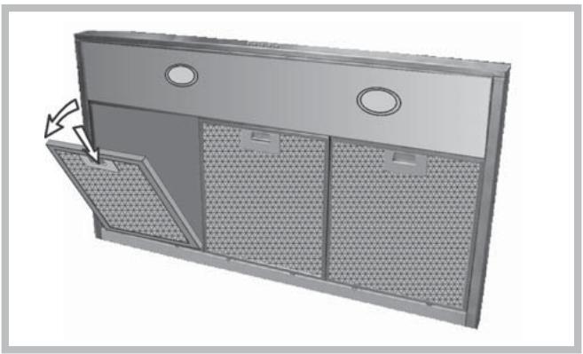
Wash the filters by hand or in the dishwasher using a neutral detergent. If they are washed in the dishwasher, any loss of colour will not jeopardise functioning of the filters in any way.
Clean the grease filters every 2 months on average depending on how heavily the hood is used.
Replacing the charcoal filter
If using the hood in the filtering version, the charcoal filter (P) will periodically have to be replaced. First of all, remove the metal grease filters. Push the catch towards the inside and remove the charcoal filter from its seat.
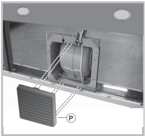
Replace the charcoal filter with one of the same type by carrying out the operations in reverse order.
Replace the charcoal filter on average every 6 months depending on how heavily the hood is used.
Replacing the lamps
Pay particular ATTENTION when carrying out this operation and remember to remove the voltage. After having removed the grease filters, remove the light fitting, operating manually from inside the hood.
Apply light pressure to the mobile part of the 2 retainers and release it from the outside.
Unscrew the bulb and replace it with a bulb of the same type.
Re-assemble the light fitting by pushing it into its seat from the outside.
General safety
! The distance between the supporting surface for the cooking vessels on the hob and the lower part of the hood must be at least 65 cm. If the instructions for installation for the hob specify a greater distance, this has to be taken into account.
! This appliance has such technical particulars that it belongs to class II insulation, therefore it must not be earthed.
! Avoid using materials which could cause spurts of flame (flambées) near the appliance.
! When frying, take particular care to prevent oil and grease from catching fire. Already used oil is especially dangerous in this respect.
! Do not use uncovered electric grates.
! This appliance is not intended for use by persons (including children) with reduced physical, sensory or mental capabilities, or lack of experience and knowledge, unless they have been given supervision or instruction concerning use of the appliance by a person responsible for their safety. Children should be supervised to ensure that they do not play with the appliance.
! Caution: accessible parts may become hot when used with cooking appliances.
! This kitchen hood is intended for installation in domestic kitchens above cooktops, cooking devices and similar kitchen equipment.
Do not place weights above the hood.
Air vent
Should you install the ducting version, prepare the air vent hole and duct.
In the Ducting version, to get optimal conditions the air venting pipe should: be as short as possible, have the lowest number of bends (max bende angle: 90irc , be made of material approved by local authorities (according to the State), have its inner side as regular and smooth as possible. It is moreover recommended to avoid drastic changes of pipe cross section (recommended diameter: 150 mm).
! The air collected must not be conveyed into a duct used to blow off smokes from appliances fed with an energy other than electricity (central heating systems, thermosiphons, water-heaters, etc.).
! Comply with the official instructions provided by the competent authorities in merit when installing the disposal duct. In addition, exhaust air should not be discharged into a wall cavity, unless the cavity is designed for that purpose.
The room must be well aerated in case a hood
and some other heat equipment fed with an energy other than electricity (gas, oil, coal heaters, etc) operate at the same time. In fact the ducting hood, disposing of air, could create a vacuum in the room. The vacuum should not exceed 0,04mbar.
This prevents the gas exhausted by the heat source from being intaken again. It is therefore advisable to ensure the room contains air taps able to ensure a steady flow of fresh air.

Disposal
The European Directive 2002/96/EC on Waste Electrical and Electronic Equipment (WEEE), requires that old household electrical appliances must not be disposed of in the normal unsorted municipal waste stream.
Old appliances must be collected separately in order to optimise the recovery and recycling of the materials they contain and reduce the impact on human health and the environment.
The crossed out "wheeled bin" symbol on the product reminds you of your obligation, that when you dispose of the appliance it must be separately collected.
Consumers should contact their local authority or retailer for information concerning the correct disposal of their old appliance.

Italiano, 1

English, 9

Deutsch, 17

Français, 25

Espanol, 33

Portogues, 41
NL
Nederlandsl,49
Ligaçao electrolytica
Acende / Apaga as luzes


- Assembly
- Fixing to the wall
- Securing the decorative flue
- 3) Ducting version:
- 4) Filtering version:
- Electrical connection
- Filtering version
- Ducting version
- Controls
- Cleaning the hood
- Cleaning the grease filters
- Replacing the charcoal filter
- Replacing the lamps
- General safety
- Air vent
- Disposal
- Ligaçao electrolytica
Brand : INDESIT
Model : L04308004
Category : Range hood