
TEG1020UC6 - Boiler GORENJE - Free user manual and instructions
Find the device manual for free TEG1020UC6 GORENJE in PDF.


| Product type | Wall-mounted condensing gas boiler |
| Brand | Gorenje |
| Model | TEG1020UC6 |
| Dimensions (H x W x D) | 700 x 400 x 300 mm |
| Weight | 30 kg |
| Electrical supply | 230 V - 50 Hz |
| Gas supply | Natural gas (G20) or propane (G31) |
| Nominal heating power | 24 kW |
| Nominal DHW power | 28 kW |
| Seasonal efficiency (energy class) | A+ (94%) |
| Heating temperature range | 30 - 80 °C |
| DHW temperature range | 35 - 60 °C |
| Domestic hot water flow rate (ΔT 30°C) | 13 l/min |
| Expansion vessel | 8 litres |
| Flue gas connection | Concentric 60/100 mm |
| Protection rating | IPX4 |
| Main functions | Central heating and instantaneous domestic hot water production |
| Maintenance and cleaning | External cleaning with damp cloth; annual maintenance by a professional mandatory |
| Spare parts and repairability | Available through Gorenje after-sales service; repairability index: 8/10 |
| General information | User manual available in several languages; compatible with room thermostat |
Frequently Asked Questions - TEG1020UC6 GORENJE
User questions about TEG1020UC6 GORENJE
0 question about this device. Answer the ones you know or ask your own.
Ask a new question about this device
Download the instructions for your Boiler in PDF format for free! Find your manual TEG1020UC6 - GORENJE and take your electronic device back in hand. On this page are published all the documents necessary for the use of your device. TEG1020UC6 by GORENJE.
USER MANUAL TEG1020UC6 GORENJE
TEG
Instructions for Use 16
Upute za upotrebu 20
Návod k obsluze 24

The image is too blurry to recognize any text content.
![graph TD A["Top Left Valve"] --> B["Top Right Valve"] B --> C["Bottom Left Valve"] C --> D["Bottom Right Valve"] D --> E["Bottom Left Valve"] E --> F["Bottom Right Valve"] F --> G["Bottom Left Valve"] style A fill:#f9f,stroke:#333 style G fill:#f9f,stroke:#333 note1["4a"] --> B note2["3"] --> B note…](/content/2026/06/1266443/images/817073181dd541894884e444bc72476a6e1e3df9f788f169343efc2decf48255.jpg)
ANSCHLUß AN DAS ELEKTRONETZ
The image is too blurry to recognize any text content.
VORSICHT:

Dear buyer, we thank you for purchase of our product.
PRIOR TO INSTALLATION AND FIRST USE, PLEASE CAREFULLY READ THESE INSTRUCTIONS.
This water heater has been manufactured in compliance with the relevant standards and tested by the relevant authorities as indicated by the Safety Certificate and the Electromagnetic Compatibility Certificate. The technical characteristics of the product are listed on the label affixed between the inlet and outlet pipes. The installation must be carried out by qualified staff. All repairs and maintenance work within the water heater, e.g. lime removal or inspection/replacement of the protective anticorrosion anode, must be carried out by the authorised maintenance service provider.
BUILDING-IN
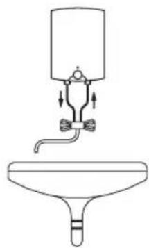
The water heater shall be built in according to the drawing and table with dimensions in a premise where there is no frost, as close as possible to the water outlets.
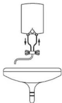
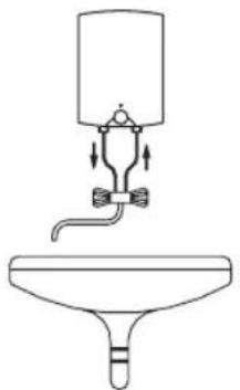
With regard to the needs, you can chose execution above the sink (TEG 1020 O/A) or an execution under the sink (TEG 1020 U/A).
TECHNICAL PROPERTIES OF THE APPLIANCE
| Type TEG 1020 O/A TEG 1020 U/A | ||
| Model TEG 10 ON TEG 10 UN | ||
| Volume [I] 10 | ||
| Weight / Filled with water [kg] 4/14 | ||
| Connection power [W] 2000 | ||
| Voltage [V ~ ] 230 | ||
| Heating time to 75°C1) [min] 22 | ||
| Quantity of mixed water by 40°C [I] 17,2 16,4 | ||
| Energy consumption 2) [kWh/24h] 0,50 0,52 | ||
1) Time for heating of the whole volume of heater with electric immersion heater by entering temperature of cold water from water supply 10° C.
2) Energy consumption to maintain stable temperature of water in the water heater 65° C at surrounding temperature 20° C, measured according to DIN 44532.
| A | B | C | D | E | |
| TEG 1020 O/A | 500 398 | 350 265 | |||
| TEG 1020 U/A | 500 122 | 350 265 |
Connection and installation dimensions of the water heater [mm]

Execution above the sink
Execution under the sink
CONNECTION TO THE WATER SUPPLY
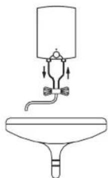
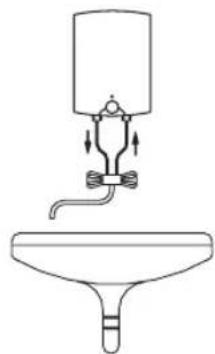
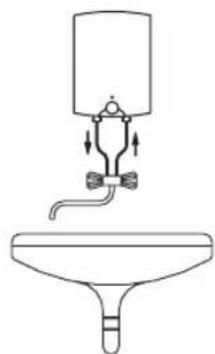
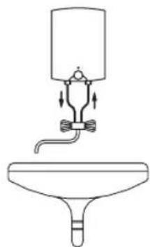
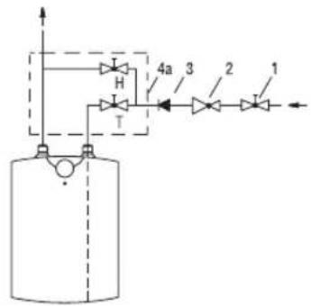
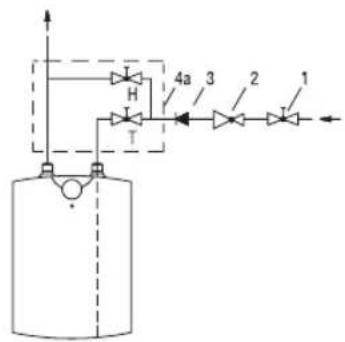
The water heater is constructed for cross-flow (non-pressure) system of installation. This system enables supply of water only at one outlet point. The connection must be performed correspondingly to the diagram of the water supply.
For cross-flow system of installation an adequate mixing tap must be purchased. For the execution above sink is needed a mixing tap above sink, and for execution under the sink the mixing tap under the sink. Inlet of cold water is marked with blue colour and the outlet of hot water is marked with red colour. Upon the inlet pipe before the mixing tap it is mandatory to built-in a non-return valve preventing the running of water of the tank if the water in the network runs short. If the pressure in water supply network surpasses 5 bar, before the mixing tap also a reduction valve must be built in.
By choice of the cross-flow mixing tap, particular attention must be paid to the data of supplier about reduction of pressure by the resistance appearing by flow of water through the mixing tap. By entirely open outlet valve this must not surpass 0,2 bar. To the outlet pipe of mixing tap no device driven by water or spray nozzle may be connected, which could cause the increase of pressure in the tank of the water heater. If these instructions shall not be respected during the operation, a damage of the heater may occur.
B
![graph TD A["Water Tank"] --> B["Valve 1"] B --> C["Valve 2"] C --> D["Valve 3"] D --> E["Valve 4"] E --> F["Return Line"] G["Return Line"] --> H["Return Line"] I["Return Line"] --> J["Return Line"] K["Return Line"] --> L["Return Line"]](/content/2026/06/1266443/images/47a5efcf28438034096cdb7fc427dfd13d84c0bc53fd38194d6a1b16ac74fe21.jpg)
Execution above the sink

Execution under the sink
Legend:
1 - Closing valve
2 - Reduction valve
3 - Non-return valve
4 – Cross-flow mixing tap - above sink H – Cold water
4a - Cross-flow mixing tap - under sink T - Hot water


Prior to the electric connection, the heater must be obligatorily filled with water. By first filling the faucet for the hot water upon the mixing tap must be opened. The heater is filled with water when the water starts to run through the outlet pipe of the mixing tap. If the heater at connection would not be filled with water, at first switching-on the damage of thermal fuse shall occur and the heater shall not operate at all.
CONNECTION OF THE WATER HEATER TO THE ELECTRIC NETWORK
Connection of the water heater to the electric network must be performed according to standards for electric installation. The heater shall be connected to electric power supply over electric cable with plug. If the built-in cable shall be replaced with a new longer, the built-in cable may be removed and the new connecting cable inserted where the cable wires shall be screwed to the connection terminal. In order to do this the plastic lining of the water heater must be removed. This is done so that at first the plate is removed, inserted in the front side of the plastic lining. The plate is released so that in the slot between the inserted plate and the plastic lining at first at the thermostat knob and on the side in front of the knob cautiously a screwdriver is pushed in. When the plate is released at both sides, it can then be removed by hand. Than the thermostat knob is removed and the screw under the knob is unscrewed. At last also all four screws for fixing of plastic lining are unscrewed and the lining removed.
Legenda:
1 - Thermostat
2 - Thermal fuse
3 - Immersion heater
4 - Pilot lamp
5 - Connection terminal
L - Live conductor
N - Neutral conductor
± - Earthing conductor

Electric installation
CAUTION: Prior to each reach in the inner of the heater you must absolutely disconnect it from electric network!
USE AND MAINTENANCE
After the connection to water and electric network the heater is ready for use. By turning the knob of thermostat at the front side of the protecting cover, the wished temperature of water 75° C is chosen. We recommend the adjustment of the knob to the position "E". Such an adjustment is the most economic, with it the temperature of water shall be approximately 55° C, the excretion of lime-stone and thermal loss shall be smaller as by adjustment to higher temperature.
The operation of electric immersion heaters is shown by pilot light which is lit during the time until the water in the heater is heating to the chosen temperature or to the intended switch off. During the heating the volume of water in the heater is increasing, which causes the dropping of water from the mixing valve. By strong squeezing of the mixing valve the dropping can not be stopped but the mixing valve can be damaged.
When the heater shall not be used during a longer time, its contents must be protected against freezing so that the electricity shall not be switched off, but the thermostat knob shall be adjusted to the position "*". With this adjustment the heater shall maintain the water temperature by approximately 9°C. But when the heater is switched-off the electric network, at risk for freezing, the water must be emptied from it.
The outside of the heater is cleaned by mild solution of detergent. The solvents or rough cleaning means should not be used. By regular service check impeccable operation shall be assured and a long lifetime of the heater. The first check must be performed by authorised service workshop after approximately two years after the first connection. At check, it necessary lime stone must be cleaned which with regard to the quality, quality and temperature of the water used is gathered in the inside of the water heater. Service workshop shall after check recommend also the date of next check.
Never try to repair any possible faults of the heater by yourself, but inform about it the nearest authorised service workshop.

Prije priključenja grijalice na elektičnu mrežu kotao grijalice moramo obvezno napuniti vodom. Pri prvomu punjenju otvorimo ručicu za toplu vodu na bateriji; kotao je pun, kad voda počne istjecati kroz odvodnu cijev baterije. Ukoliko to ne učnimo, pri prvomu će uključenju doći do kvara toplotnog osigurača te grijalica neće funkcionirati.
PRIKLJUČENJE NA ELEKTRIČNU MREŽU
Монтаж над мивка

Монтаж под мивка


Prije priključenja grijalice na elektičnu mrežu kotao grijalice moramo obvezno napuniti vodom. Pri prvomu punjenju otvorimo ručicu za toplu vodu na bateriji; kotao je pun, kad voda počne istjecati kroz odvodnu cijev baterije. Ukoliko to ne učnimo, pri prvomu će uključenju doći do kvara toplotnog osigurača te grijalica neće funkcionirati.
PRIKLJUČENJE NA ELEKTRIČNU MREŽU
Mbi vendin e harxhimit

Nën vendin e harxhimit
Legjenda:
KUQJA NË RRJETIN ELEKTRIK

Fixarea boilerului deasupra chiuvetei
BRANŞAREA LA REȚEAUA ELECTRICĂ

KOPPLING TILL ELNÄTET

ZAPOJENIE DO ELEKTRICKEJ SIETE
![graph TD A["Top Left Valve"] --> B["Top Right Valve"] B --> C["Bottom Left Valve"] C --> D["Bottom Right Valve"] D --> E["Bottom Left Valve"] E --> F["Bottom Right Valve"] F --> G["Bottom Left Valve"] style A fill:#f9f,stroke:#333 style G fill:#f9f,stroke:#333 note1["4a"] --> B note2["3"] --> B note…](/content/2026/06/1266443/images/43dad4ca413a0ac567d74a93f0c90fc811fb60275b31af217690c58e13b6c766.jpg)




- TEG
- ANSCHLUSS AN DAS ELEKTRONETZ
- VORSICHT
- PRIOR TO INSTALLATION AND FIRST USE, PLEASE CAREFULLY READ THESE INSTRUCTIONS
- BUILDING-IN
- CONNECTION TO THE WATER SUPPLY
- B
- LEGEND
- CONNECTION OF THE WATER HEATER TO THE ELECTRIC NETWORK
- LEGENDA
- CAUTION: PRIOR TO EACH REACH IN THE INNER OF THE HEATER YOU MUST ABSOLUTELY DISCONNECT IT FROM ELECTRIC NETWORK
- USE AND MAINTENANCE
- PRIKLJUČENJE NA ELEKTRIČNU MREŽU
- LEGJENDA
- KUQJA NË RRJETIN ELEKTRIK
- BRANŞAREA LA REȚEAUA ELECTRICĂ
- KOPPLING TILL ELNÄTET
- ZAPOJENIE DO ELEKTRICKEJ SIETE
Brand : GORENJE
Model : TEG1020UC6
Category : Boiler