
UFO 333/MX - Audio/video converter KATHREIN - Free user manual and instructions
Find the device manual for free UFO 333/MX KATHREIN in PDF.


| Product Type | Audio/video converter |
| Brand | Kathrein |
| Model | UFO 333/MX |
| Dimensions (L x W x H) | Approximately 15 x 10 x 3 cm |
| Weight | Approximately 200 g |
| Power supply | 12V DC, 500 mA power adapter |
| Video inputs | 1 x HDMI, 1 x Composite (RCA) |
| Video outputs | 1 x HDMI, 1 x Composite (RCA) |
| Audio inputs | 1 x HDMI (built-in), 1 x Stereo RCA (L/R) |
| Audio outputs | 1 x HDMI (built-in), 1 x Stereo RCA (L/R) |
| Supported video formats | PAL, NTSC, SECAM |
| Maximum resolution | 1080p |
| Main features | HDMI to Composite conversion and vice versa, audio extraction, scaling |
| Housing material | ABS plastic |
| Operating temperature | 0 °C to 40 °C |
| Maintenance and cleaning | Clean with a soft, dry cloth. Do not use solvents. |
| Safety | Do not expose to moisture or shocks. Use only the supplied adapter. |
| Spare parts and repairability | Repairability index not provided. Contact Kathrein customer service. |
| General information | Manual available in multiple languages. Visit Kathrein website for more information. |
Frequently Asked Questions - UFO 333/MX KATHREIN
User questions about UFO 333/MX KATHREIN
0 question about this device. Answer the ones you know or ask your own.
Ask a new question about this device
Download the instructions for your Audio/video converter in PDF format for free! Find your manual UFO 333/MX - KATHREIN and take your electronic device back in hand. On this page are published all the documents necessary for the use of your device. UFO 333/MX by KATHREIN.
USER MANUAL UFO 333/MX KATHREIN
■ DVB-S/HDTV channel unit for installation in UFO®compact base units or UFG 3xx, UFG 4xx expansion units
■ For processing two HDTV Sat or DVB Sat transponders in a COFDM output signal
Permits the removal of individual channels from two 8PSK-modulated DVB-S signals (or QPSK-modulated DVB-S signals), the multiplexing of the two transport streams and their conversion into one COFDM-modulated output signal
■ Two inputs A/B, settable via the central controller of up to 8 Sat signals (e.g. for H/V switching and creating the cable NIT for two polarities)
DiSEqC™ to control external DiSEqC™ multi-switches (one can only use DiSEqC™ matrices with eight Sat-IF inputs (two satellites))
■ All essential transmission parameters can be set using the central controller
■ Output level can be set and switched off via the central controller
■ Adjacent channel compatible
■ MPEG transport stream processor
• To set a constant output data rate (stuffi ng) with PCR correction
• With channel filter to remove individual TV and radio channels (easy setting using the USW 30 and UFX 31x)
- For NIT matching (cable NIT; additionally a UFX 31x is required)
• For CAT matching, e.g. to set the operator ID
■ Extendable using a UFZ 394 Common Interface retrofit kit to add two CA modules
■ COFDM modulator with 2K IFFT for QPSK, 16/64 QAM (factory pre-set to 64 QAM)
Output (F connector socket)
Panel for enclosed label
Socket for connecting controller (Mini-DIN)
Connection for power supply bus Sat-IF input B (F connector socket)
Sat-IF input A (F connector socket)

■ MPEG transport stream processor and COFDM modulator as FPGA solution
■ Software update possible via control interface
■ Permissible ambient temperature when used in:
• base unit with fan (UFG 412): -20°C to +50°C
• and extension unit without fan (UFG 3xx): -20°C to +40°C
■ Required controller software version: from V9.40
■ Dimensions (W x H x D) in mm: 265 x 27 x 170
■ Packing unit/weight (pc./kg): 1 / 0.8
Technical Specification
| TypeOrder no. | Frequency range(MHz) | Input level3) | InputData rate | Outputdata rate4) | Modulation ErrorRate | Max. outputlevel | Setting range/Output level | Currentconsumption | |
| Input1)950-2150 | Output2)47-862 | (dBμV) | (MS/s) | (MBit/s) | (dB) | (dBμV) | (dBμV) | (V/mA) | |
| UFO 333/MX20610110 | Ch Ch | ■ | 55-85 | 2-45 (S1)2-30 (S2) | 4.98-31.67 | 33.5 (< 400 MHz)32 (> 400 MHz) | 91 81-91 | 5 V/120012.5 V/75031 V/7 | |
1 Settable in 1 MHz steps
2) Settable in 7 or 8 MHz channel plan, fi ne tuning in 250 kHz steps
3) If both inputs A and B are connected, ensure that the input levels are about equal for each
4) Depending on COFDM parameter Guard Interval, code rate and modulation
Note: The most up-to-date version of these user instructions can be found on the Kathrein homepage under: "www.kathrein.de" → Service → Operating instructions
Setup instructions
The DVB-S(2) trans-modulator/multiplexer (2 x QPSK/8PSK on COFDM) is set up using the controller on the base unit UFG 404 or UFG 412 or UFG 412/R.
Required controller software version: from version V9.40
For setup, connect the controller to the module. The buttons listed below refer to the controller (see also the user instructions for the UFG 404, etc. base units and the UFG 300 controller).
Note: The settings and numerical values shown below are intended as an example and do not necessarily match the delivery status.
Select the desired parameter using the "<" and "> " buttons.
The selected parameter flashes in the display.
The setting is performed using the "+" and "-" buttons and where necessary using the "Change setting mode" button
The sub-menus are activated and deactivated by pressing the "Sub-menu" button
Finally, press "M" to save the setting in the module.
Note: If the controller is disconnected from the module by pressing the "M" button without saving the settings, the settings originally stored in the module are reactivated.
The following representation shows the appearance of the display after plugging in the controller.
Note: The indicator (“*”) flashes at top right during channel unit initialisation.

Main menu (all symbols shown)
Displays
“*” Left of “TP”:
Indicates "desired operating mode not yet reached", displayed permanently in case of error. If the indicator is flashing, the channel unit cannot operate properly.
Reasons for this include:
- Input frequency or symbol rate set incorrectly - No input signal
Right of "Outp."
The channel unit output is switched off
If the front end is not clicked into place (no Sat input signal), the following display appears:

Main menu (front end not clicked into place)
The modulation type of the satellite input signal can be seen on the main menu display. It is always QPSK in operating mode DVB-S1. Both QPSK and 8PSK are available in DVB-S2 mode.

Main menu (example for DVB-S1)
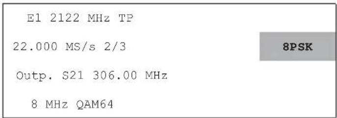
Main menu (example of DVB-S2)
1. Configuration of the channel unit
1.1 Selection of the input tuner
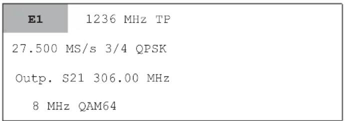
The main menu permits the selection and setting of the two input tuners. The changeover is performed using "+" and "-"

Main Menu
The following settings are available: E1 or E2
1.2 Selecting the input socket
The socket A or B to be used for the input can be selected in the sub-menu for the selected input tuner. Press the "Sub-menu" button to activate the sub-menu; press the "Sub-menu" button again to deactivate it.

Main Menu
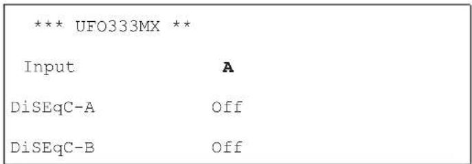
Sub-menu for the input tuner E1
1.3 DiSEqC TM setting
The DiSEqC™ controller for a matrix can be set in the sub-menu for the input socket that was selected. Press the "Sub-menu" button 📋 to activate the sub-menu; press the "Sub-menu" button 📋 again to deactivate it.
Main Menu

Sub-menu for channel unit |
Select the desired level using the "+" and "-" buttons. The following settings are available:
DiSEqCTM-A or -B
| off | The DiSEqCTM controller is switched off |
| Ver-Low-1 | In connection with a matrix: Vertical low band position 1 |
| Hor-Low-1 | In connection with a matrix: Horizontal low band position 1 |
| Ver-High-1 | In connection with a matrix: Vertical high band position 1 |
| Hor-High-1 | In connection with a matrix: Horizontal high band position 1 |
| Ver-Low-2 | In connection with a matrix: Vertical low band position 2 |
| Hor-Low-2 | In connection with a matrix: Horizontal low band position 2 |
| Ver-High-2 | In connection with a matrix: Vertical high band position 2 |
| Hor-High-2 | In connection with a matrix: Horizontal high band position 2 |
Note: When the DiSEqCTM controller is switched on, a DC voltage of approx. 12 V is present at the input sockets! If no matrix is used, the DiSEqCTM controller cannot be switched on.
The DiSEqC ™ controller can be set up only in the sub-menu for the input tuner 1 (E1). The selected information available in the sub-menu for the input tuner 2 (E2) is displayed solely for information. It cannot be selected there. The DiSEqC ™ controller applies to both E1 and E2. Each of inputs A and B can be plugged into either input tuner.
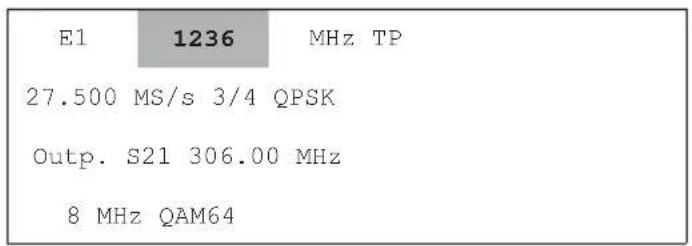
1.4 Selecting input frequency
The input frequency in the active channel unit is selected using the “<” and “>” buttons. The input frequency can be set continuously from 950 MHz to 2150 MHz in 1 MHz steps using the “+” and “-” buttons.

Main Menu
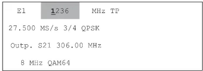
Main menu (example for digit-by-digit setting)
The setting can also be made on a digit-by-digit basis:
- Press the "Change setting mode" button 🎨 (starts the mode)
- The first digit flashes and can be input directly using the numeric pad on the keyboard
• After the first digit has been input, the second flashes, and so on - To make a correction, press the "Back" button to skip one place to the left.
- After the last digit has been set, press the "Change setting mode" button ⏻ to end the mode.
The current SNR and the automatically detected operating mode, DVB-S or DVB-S2 of the front end are displayed in the input frequency sub-menu.
Press the "Sub-menu" button to activate the sub-menu; press the "Sub-menu" button again to deactivate it.
Main Menu

Sub-menu for "Input frequency" (no signal)
The displays of SNR and DVB operating modes are valid only in regular operation with the front end clicked into place.
Note: For the SNR display, all parameters must be set and the indicator “*” must not be flashing. Trouble-free operation of the systems requires SNR > 12 dB.
1.5 Selecting the input symbol rate
Main Menu

Main menu (example for digit-by-digit setting)
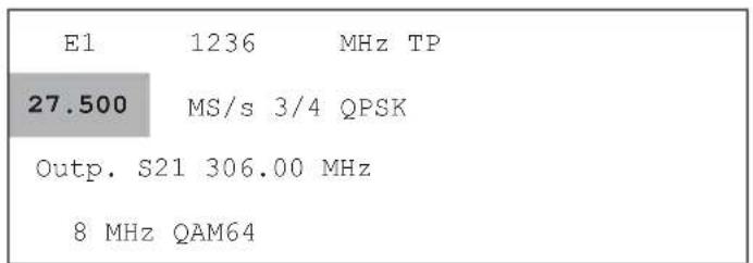
The input symbol rate is selected using the "<" and "> " buttons.
The input symbol rate can be adjusted continuously from 2.0 MS/s to 45 MS/s (DVB-S) or 2.0 MS/s to 30 MS/s (DVB-S2) in 0.1 MS/s steps using the "+" and "-" buttons.
The digits can also be entered individually to an accuracy of 0.001 MS/s:
- Press the "Change setting mode" button ⚪ (starts the mode)
- The first digit flashes and can be input directly using the numeric pad on the keyboard
• After the first digit has been input, the second flashes, and so on - To make a correction, press the "Back" button to skip one place to the left
- After the last digit has been set, press the "Change setting mode" button ⚪ to end the mode.
Note: The code rate (e.g. 3/4) is automatically determined once the channel unit has locked on to the set transponder.
1.6 Selecting output channel or output frequency
The output channel unit is selected using the "<" and "> " buttons.
You can use the "+" and "-" buttons to adjust the channel from 48 to 96 MHz and 114 to 858 MHz in 8 MHz increments 1 .

Main Menu

"Output channel" sub-menu
1) We recommend the use of frequencies only up to 834 MHz (K66). If higher channels are used this can lead to picture distortion on some receivers.
Fine adjustments can be made to the output frequency in the output channel sub-menu in 250 kHz steps. Press the "Sub-menu" button 📋 to activate the sub-menu; press the "Sub-menu" button 📋 again to deactivate it.
1.7 Selecting the output level
The output channel unit is selected using the "<" and ">" buttons.

Main Menu

"Output channel" sub-menu
The output level of the output channel can be adjusted in 40 steps from a maximum level "0" to a minimum level of "-40" using the output channel sub-menu. Press the "Sub-menu" button ☐ to activate the sub-menu; press the "Sub-menu" button ☐ again to deactivate it. The output level is selected using the "<" and ">” buttons and adjusted using the "+" and "-" buttons.
1.8 Switching the output on/off
The output channel unit is selected using the "<" and ">" buttons.
Main menu (output I switched off)

"Output channel" sub-menu
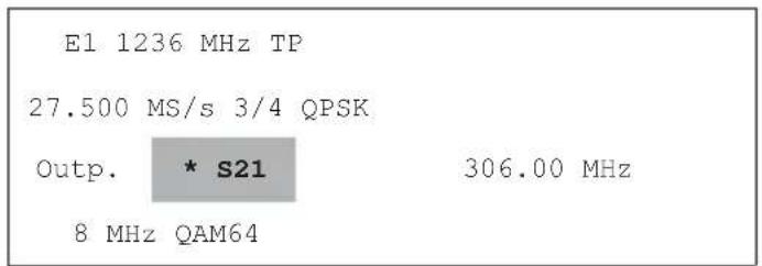
The output can be switched on and off using the output channel sub-menu.
The following settings are available: on or off
Press the "Sub-menu" button to activate the sub-menu; press the "Sub-menu" button again to deactivate it.
The output is selected using the "<" and "> " buttons and adjusted using the "+" and "-" buttons.
When the output is switched off an indicator “*” is shown in the main menu, on the left beside the output channel.
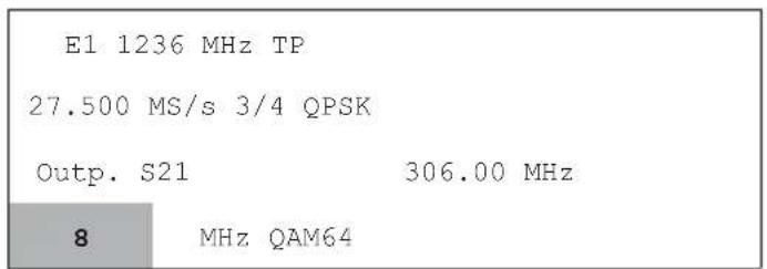
1.9 Selecting the output channel bandwidth
The output channel bandwidth is selected using the "<" and ">" buttons.
Main Menu
Use the “+” or “-” keys to set the output channel bandwidth to the values 6 MHz, 7 MHz, or 8 MHz.
1.10 Selecting the COFDM mode
The COFDM mode of the output signal is selected using the "<" and "> " buttons.
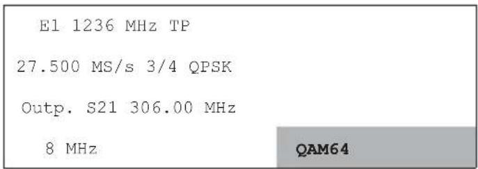
Main Menu
Use the “+” or “-” keys to set the modulation type of the COFDM carriers to the values QPSK, QAM16, or QAM64 defined in the DVB-T specification.
Note: Since the possible output data rate for COFDM-modulated signals is normally lower than the input data rate, it is recommended to use the highest QAM stage (QAM64) if possible. The lower QAM stages QAM16 and QPSK offer a higher interference resistance but a lower transmissible data rate. Table 1 in the appendix shows the connection between modulation type, code rate, guard interval and the possible maximum data rate.
1.11 Selecting the operating mode for the COFDM modulator
In the sub-menu of the COFDM mode you can select the operating mode (source signal) for the COFDM modulator.
Press the "Sub-menu" button ☐ to activate the sub-menu; press the "Sub-menu" button ☐ again to deactivate it. The modes are selected using the "<" and ">” buttons and adjusted using the "+" and "-" buttons.

Main Menu
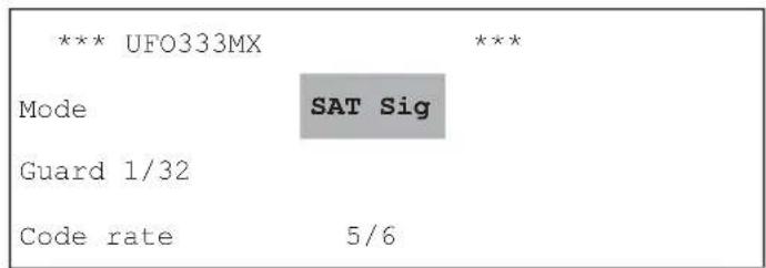
Sub-menu for "COFDM modes"
The following settings are available:
| Mode | SAT-Sig | Normal mode,the SAT input signal is transmodulated, in the case of input signal interferences only full bytes (0xFF) are modulated |
| PRBS | Test mode: the COFDM signal is modulated with a PRBS-23 sequence, normal mode is not available in this setting | |
| CW | Test mode: sine wave signal for levelling using simple measurement devices, normal mode is not available in this setting |

Main menu (display in PRBS mode)
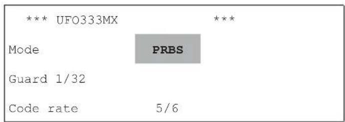
"COFDM mode" sub-menu (for setting the PRBS)
Note: In PRBS mode you can set the COFMD parameter guard interval and code rate. The CW mode can be used for output level measurement.

Main menu (display in the CW mode)

"COFDM mode" sub-menu (for setting CW)
1.12 Selecting the COFDM parameters
In the PRBS mode sub-menu you can set the COFMD parameter guard interval and code rate. The parameters can only be selected if SAT-Sig or PRBS operating mode has been selected.
The output signal parameters are selected using the "<" and "> " buttons and adjusted using the "+" and "-" buttons.

Main Menu

"QAM stage" sub-menu
The following settings are available:
Guard 1/4, 1/8, 1/16, 1/32 Code rate 1/2, 2/3, 3/4, 5/6, 7/8
Lower values permit higher data rates Higher values permit higher data rates at the cost of reduced error protection
1.13 Transport stream processor: Channel multiplex
Note: The Electronic Programme Guide (EPG) shows only the programmes that are available on the E1 input tuner. This should be recognised when scheduling.

Main Menu

"Transport stream processor" sub-menu
The setting of the channel multiplex "filter" is performed in the "TP" (transport stream processor) sub-menu. The "TP" transport stream processor is selected using the "<" and ">” buttons and the sub-menu is called up using the "Sub-menu" button. This sub-menu can be exited only when the cursor is on the "Back" parameter. To do this, use the "<" and ">” buttons to select the parameters "on" and "off" and press the "Sub-menu" button to return to the main menu.
The channel multiplex "filter" is selected using the "<" and "> " buttons.
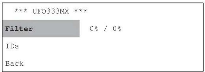
"Transport stream processor" sub-menu

When changing to the "Filter" sub-menu
To process the channel list for the channel filter, press the "Sub-menu" button 📋 on the "Filter" parameter in the channel filter. This reads in the current channel table from the transponder. A progress bar appears while this is done.
As soon as the channel unit has successfully determined this information, the sub-menu for adjustment is displayed.
If a CI retrofit kit is fitted an additional parameter is shown in the second line, see also the next chapter.
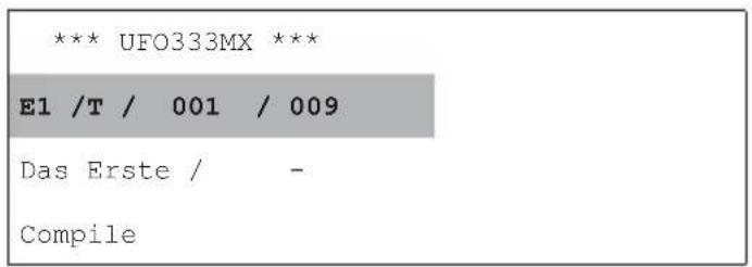
The first line shows the type of the programme that was selected, together with the number of the channel and the number of channels on the transponder.
T = TV channel
R = Radio channel
D = Data service
Channel no. (e.g. 001)
/ Quantity (e.g. 009)
of the selected channel
of the channels in the transponder
The second line shows the channel name, together with its filter status (+ or -).
The default setting for the status of the channels that are displayed is “-”, i.e. no channels are transmitted when the channel filter is switched on, but the channel list is not being processed.
The "Compile" button in the third line starts the compilation of the channel list, which then becomes effective.
The selection of the channels carried over is performed using the "+" and "-" buttons, where the status "+" means the channel will be carried over and the status "-" means it will be removed. The "Status" parameter is selected using the "<" and "> " buttons.
The settings become effective when the filter table is compiled. This is done using the "<" and "> " buttons; select the "Compile" parameter and use the "+" or "-" buttons to initiate the compilation of the channel table.

On compiling the channel filter
If the channel multiplex filter is compiled, a display appears next to the parameter indicating the current output data rate. Since the data rate can vary depending on the channel content, the instantaneous and maximum values are displayed. The value range runs from 0 to 100 percent, where 100 percent indicates that the channel unit is overloaded.
Note: For safe scheduling, the maximum possible data rate for the desired channels should be requested from the relevant satellite signal playout centre.
Since the channels are selected for 2 tuners and only one COFDM channel is used as output, this can lead to the maximum available data rate being exceeded if too many channels are selected in the channel multiplex filter.
Note: Only average values that can vary based on channels are displayed. To ensure error-free operation you should plan for at least 10 to 15 % spare capacity, i.e. the data rate utilisation should not be greater than 85 to 90 %.
Each of the two input tuners can pass through a maximum of 20 channels, so the output channel can accommodate a maximum of 40 channels.
Note: If the maximum possible number of channels carried over is exceeded, an error message appears.
The "channel fi Iter" sub-menu is exited using the "Sub-menu" button. To do this, select the "<" or "> " on the parameter "Back".
1.14 Transport stream processor: changing IDs


Main Menu "Transport stream processor" sub-menu
The setting of the "ID" is performed in the TP (Transport stream processor) sub-menu.
The "TP" transport stream processor is selected using the "<" and ">” buttons, and the sub-menu is called up using the "Sub-menu" button.
The "IDs" function is called up using the "<" and ">” buttons, and the sub-menu is called up using the "Sub-menu" button. Here you can edit the operator ID, the transport stream ID and the original network ID as required.

"Transport stream processor" sub-menu

Sub-menu for "IDs"
1.14.1 Operator ID (OID)
The "OID" CAT operator ID can be set in the IDs sub-menu. To do so, use the "<" or "> " keys to select "orig" next to the OID parameter and then use the "+" or "-" to set the "edit" value. The OID value now appears in hexadecimal notation. In the "edit" setting you can modify the value. To do this, select the value using the "> " key. Use the "+" or "-" key to change the current value in ± 1 increments. Alternatively you can also select numeric setting mode by pressing the button. In numeric mode each digit can be modified by pressing the "+" or "-" keys in ± 1 increments. The values available are "00h" to "FFh".
1.14.2 Transport stream ID (TSID) and original network ID (ONID)
As the data rate of a COFDM-modulated transport stream is normally lower than the data rate of the received transport stream, it may be necessary to distribute the services of an individual transport stream at the input to several transport streams at the output. In their search mode some receivers do then not detect all channels that were originally compiled in the original transport stream. In this case they require the "TSID" transport stream ID to be adjusted and/or "ONID" original network ID.
Note: The TSID and the ONID are 16-bit numbers. A transport stream can be differentiated from all other transport streams in a DVB-T system by a unique combination of TSID and ONID. For DVB the ONID normally describes the original location of a transport streams.
Menus are available for editing the TSID and the ONID. The values can be modified by selecting the corresponding "orig" entry using the "<" or ">” buttons and set to the "edit" value by using the "+" or "-" buttons. The current values of the TSID and ONID from the processed transport stream are displayed in hexadecimal notation. In the "edit" setting you can modify the values of the corresponding IDs. To do this, select the value using the ">” button. Use the "+" or "-" key to change the current value in ± 1 increments. Alternatively you can also select numeric setting mode by pressing the 🎨 button. In numeric mode each digit can be modified by pressing the "+" or "-" keys in ± 1 increments. All IDs should be entered in hexadecimal format. Possible values are "00h" to "FFh" for the OID and "0000h" to "FFFFh" for the TSID and the ONID.
Note: Only experienced users should modify the TSID or ONID. If several channels (services) of a SAT transport stream are distributed to multiple COFDM transport streams, it is possible that the receiver cannot automatically detect all channels because in this case the uniqueness of the TSID / ONID pair is lost. In this case please proceed as follows:
- Preferably the ONID should be modified. If possible, set it to a value between FF00h and FFEEh. This range is reserved for private use and is not used by public network operators.
- If the channel search is unsuccessful despite the ONID adjustment, the TSID can be modified. Please ensure that all TSIDs in a system are adjusted to guarantee uniqueness for each transport stream.
This sub-menu can be exited only when the cursor is on the "OID" parameter. To do this, use the "<" and "> " buttons to select "OID" and press the "Sub-menu" button to return to the main menu.
Note: Modifying the TSID and the ONID requires that the channel filter is active.
1.15 Conditional Access with it CI retrofit kit (only if CI retrofit kit fitted)
The UFZ 394 CI retrofit kit (200610097) can be fitted to enable decoding of encrypted channels. Fitting is described in the documentation. If the UFZ 394 CI retrofit kit is fitted, the software detects this automatically and modifies the menu contents accordingly.

Main Menu
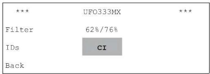
"Transport stream processor" sub-menu
The transport stream processor "TP" is selected using the "<" and ">” buttons and the sub-menu is called up using the "Sub-menu" button. If the UFZ 394 CI retrofit kit is detected, the "CI" parameter will appear.
“CI” is selected using the “<” and “>” buttons and the sub-menu below is called up using the “Sub-menu” button ☐.
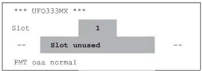
Sub-menu for "CI"
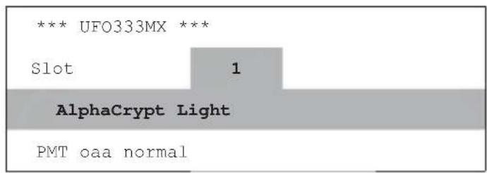
Sub-menu for "CI"
You can select between the CI module slot "1" display and slot "2" display by setting the slot number using the "<" or "> key, and by setting "1" or "2" using the "-" and "+" buttons. If a CI module is plugged into the respective slot (1 or 2), its name is displayed; otherwise a message that the slot is empty is displayed.
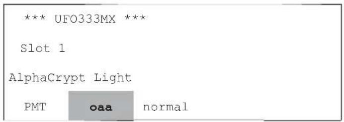
Sub-menu for "CI"

Sub-menu for "CI"
If more than one channel is decoded using a CAM (Conditional Access Module), there are different ways by which CAMs manage the list of these channels. If the first parameter in the bottom line is selected using the "<" and "> " buttons, the "+" and "-" buttons can be used to select between "Only Add Add", "oaa" and "First More More Last" "fmml".
The second parameter in the bottom line relates to the updating of the PMT if there have been changes to the management information. When the "<" and "> " buttons have been selected, the "+" and "-" buttons can be used to select between "Update the complete channel list", "normal" and "List update", "optimised". Whilst practically all CAMs support the "normal" setting, there are some CAMs that do not permit the "optimised" setting.
Note: An inappropriate "normal" or "optimised" setting can cause loss of all encrypted channels; it may be necessary to switch the module off and on again to recover from this.
Note: The selection of the channels to be decoded is performed in the Channel filter menu.
The "TP" transport stream processor is selected using the "<" and ">” buttons and the sub-menu is called up with the "Sub-menu" button.
The "Filter" channel filter is selected if necessary using the "<" and "> " buttons and is called up using the "Sub-menu" button".
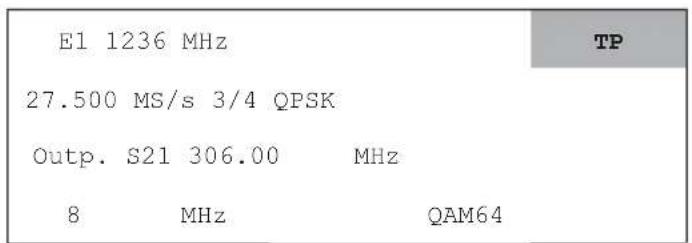
Main Menu

"Transport stream processor" sub-menu
In addition, for the "1.13 Transport stream processor: Channel filter", if the CI retrofit kit is fitted a selection facility appears in the top line at the far right. This is for decoding the module slot provided (1 or 2), and offers the following selection options:
“-” = No decoding
“1” = Decoding via CAM 1
“2” = Decoding via CAM 2
Note: Only channels (T, R or D) from the E2 input tuner can be decoded.
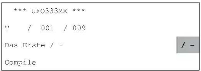
"Filter" sub-menu

"Filter" sub-menu
For this the "<" and ">" buttons may be used to select the parameters and the "+" and "-" buttons to select between "-", "1" and "2". The settings become effective when the filter table is compiled. This is done using the "<" and "> " buttons; select the "Compile" parameter and use the "+" or "-" buttons to initiate the compilation of the channel table. The menu is exited by pressing the "Sub-menu" button. If this brings you back to "Transport stream processor" in the sub-menu, this can be exited only when the cursor is on the filter's "On/Off" parameter.
2. Appendix
2.1 Use data rate (Mbit/s) for all combinations of code rate, modulation procedure and guard interval
| Mapping Code rate R | Guard interval Δ/T | U | |||
| 1/4 1/8 1/16 1/32 | |||||
| QPSK | 1/2 4.98 5.53 5.85 6.03 | ||||
| 2/3 6.64 7.37 7.81 8.04 | |||||
| 3/4 7.46 8.29 8.78 9.05 | |||||
| 5/6 8.29 9.22 9.76 10.05 | |||||
| 7/8 8.71 9.68 10.25 10.56 | |||||
| 16 QAM | 1/2 9.95 11.06 | 11.71 | 12.06 | ||
| 2/3 13.27 14.75 15.61 | 16.09 | ||||
| 3/4 14.93 16.59 17.56 | 18.10 | ||||
| 5/6 16.59 18.43 19.52 | 20.11 | ||||
| 7/8 17.42 19.35 20.49 | 21.11 | ||||
| 64 QAM | 1/2 14.93 16.59 17.56 | 18.10 | |||
| 2/3 19.91 22.12 23.42 | 24.13 | ||||
| 3/4 22.39 24.88 26.35 | 27.14 | ||||
| 5/6 24.88 27.65 29.27 | 30.16 | ||||
| 7/8 26.13 29.03 30.74 | 31.67 | ||||
Table 1: Output data rate for various COFDM parameters
3. Notes
Note: When expanding existing systems (still using power supply unit BN 1681794) with UFO 371/TP, note that this power supply unit has a lower power rating. Therefore check the power consumption information on the power supply unit label.
If the UFG 404 base unit is used, check that the maximum permissible loading of the power supply unit is not exceeded.
Note: A description of the extended functions such as configuration von "Pass-Drop-PID lists" can be found in the user instructions for the control elements used, such as UFG 300 or USW 30.

Electronic equipment is not domestic waste - in accordance with directive 2002/96/EC OF THE EUROPEAN PARLIAMENT AND THE COUNCIL dated 27 th January 2003 concerning used electrical and electronic appliances, it must be disposed of properly.
At the end of its service life, take this unit for disposal to an appropriate official collection point.
936.3940/A/ZWT/1211/e - Technical data subject to change.
Caractéristiques
R = programme radio


- SETUP INSTRUCTIONS
- DISPLAYS
- CONFIGURATION OF THE CHANNEL UNIT
- 1.1 SELECTION OF THE INPUT TUNER
- 1.2 SELECTING THE INPUT SOCKET
- 1.3 DISEQC TM SETTING
- 1.4 SELECTING INPUT FREQUENCY
- 1.5 SELECTING THE INPUT SYMBOL RATE
- 1.6 SELECTING OUTPUT CHANNEL OR OUTPUT FREQUENCY
- 1.7 SELECTING THE OUTPUT LEVEL
- 1.8 SWITCHING THE OUTPUT ON/OFF
- 1.9 SELECTING THE OUTPUT CHANNEL BANDWIDTH
- 1.10 SELECTING THE COFDM MODE
- 1.11 SELECTING THE OPERATING MODE FOR THE COFDM MODULATOR
- 1.12 SELECTING THE COFDM PARAMETERS
- 1.13 TRANSPORT STREAM PROCESSOR: CHANNEL MULTIPLEX
- 1.14 TRANSPORT STREAM PROCESSOR: CHANGING IDS
- 1.14.1 OPERATOR ID (OID)
- 1.14.2 TRANSPORT STREAM ID (TSID) AND ORIGINAL NETWORK ID (ONID)
- 1.15 CONDITIONAL ACCESS WITH IT CI RETROFIT KIT (ONLY IF CI RETROFIT KIT FITTED)
- APPENDIX
- 2.1 USE DATA RATE (MBIT/S) FOR ALL COMBINATIONS OF CODE RATE, MODULATION PROCEDURE AND GUARD INTERVAL
- NOTES
- CARACTÉRISTIQUES
Brand : KATHREIN
Model : UFO 333/MX
Category : Audio/video converter