
UFO 340 - Audio/video converter KATHREIN - Free user manual and instructions
Find the device manual for free UFO 340 KATHREIN in PDF.


| Product type | Audio/video converter |
| Brand | Kathrein |
| Model | UFO 340 |
| Dimensions (W x D x H) | 200 x 150 x 50 mm |
| Weight | 0.5 kg |
| Power supply | 12 V DC, 500 mA |
| Power consumption | 6 W |
| Video inputs | 1 x Composite (RCA), 1 x S-Video |
| Video outputs | 1 x Composite (RCA), 1 x S-Video |
| Audio inputs | 2 x RCA (L/R) |
| Audio outputs | 2 x RCA (L/R) |
| Supported video formats | PAL, NTSC, SECAM |
| Maximum resolution | 720 x 576 (PAL) |
| Main functions | Audio/video conversion, source switching, signal amplification |
| Operating temperature | 0 °C to 40 °C |
| Operating humidity | 20% to 80% (non-condensing) |
| Housing material | ABS plastic |
| Maintenance and cleaning | Clean with a soft dry cloth. Do not use chemical products. |
| Safety | Use only the provided power adapter. Do not expose to moisture. |
| Spare parts and repairability | Repairability index: 6.0/10. Parts available on request. |
Frequently Asked Questions - UFO 340 KATHREIN
User questions about UFO 340 KATHREIN
0 question about this device. Answer the ones you know or ask your own.
Ask a new question about this device
Download the instructions for your Audio/video converter in PDF format for free! Find your manual UFO 340 - KATHREIN and take your electronic device back in hand. On this page are published all the documents necessary for the use of your device. UFO 340 by KATHREIN.
USER MANUAL UFO 340 KATHREIN
Stereo 7,02/7,20 MHz
Vol 3 Vid 2 AV
Stereo 7,02/7,20 MHz
Vol 3 Vid 2 AV
Stereo 7,02/7,20 MHz
Vol 3 Vid 2 AV
Hauptmenü
***
UFO 340
Stereo 7,02/7,20 MHz
Vol 3 Vid 2 AV
***
UFO 340
***
Stereo 7,02/7,20 MHz
Vol 3 Vid 2 AV
***
UFO 340
***
Stereo 7,02/7,20 MHz
Vol 3 Vid 2 AV
Stereo 7,02/7,20 MHz
Vol 3 Vid 2 AV
Stereo 7,02/7,20 MHz
Vol 3 Vid 2 AV
Stereo 7,02/7,20 MHz
Vol 3 Vid 2 AV
UFO® compact Processing System Twin Sat TV channel unit
●Twin Sat TV channel unit for use in UFO®compact base and extension units UFG 3xx
●For processing of two independent satellite signals in conventional TV standards (PAL, SECAM) with analogue subcarriers and conversion to the output frequency range from 110 MHz to 862 MHz
●Adjacent channel compatible
●For TV standards B/G, D/K, I
●Noise-reducing Sat subcarrier processing, compatible with Wegener Panda I
●Audio operating mode: Mono, stereo, dual sound
●Data line decoder for automatic selection of the audio operating mode (mono, stereo, dual sound)
●C-band compatible
●FM threshold: 7 dB
●Output level is adjustable via the control unit of the base module carrier
●Output signal can be disengaged via the control unit
●A Sat TV signal enables generation of a black screen for a channel (Twin A)
(e.g. for reproduction of Sat radio programmes via a TV channel)
●Decoder interface for one channel (Twin A). A/V signal is switchable by means of external switching voltages (decoder, video recorder). Configuration is possible via the control unit
CE A

Electronic equipment is not household waste – in accordance with directive 2002/96/EC OF THE EUROPEAN PARLIAMENT AND THE COUNCIL of 27th January 2003 on used electrical and electronic equipment, it must be disposed of properly. At the end of its service life, take this unit for disposal at a relevant official collection point.

Technical data
| Frequency Level/Impedance Decoder or AV interface | RF band- FM- Sat- Supply voltage/ Amb. | SAT | hold | carrier frequency | current drain (V/mA) 12 | ature limit | |||||||
| Input Output | 2) Input Output Level/Impedance width thres- Audio voltage/typ. temper- | ||||||||||||
| Channel in the range of 920–2150 MHz 1) | 110–862 MHz 3) | 48–80 dBμV/75 Ohm | 93 dBμV 4) /75 Ohm | Comp. colour | BB | Audio | Comp. colour | Audio | |||||
| 1 Vss/75 Ohm 5) | 1 Vss/75 Ohm 5) 6) 0.3 Vss75 Ohm 5) 7) | 1 Veff10 kOhm 8) asymm. | 1 Vss/75 Ohm | 1 Veff/10 kOhm 9) asymm. | 27–36 MHz | 7 dB 10) | 5.5–9 MHz 1) | 5/11602.5/39031/9 | -20 °Cto50 °C | ||||
1) Independently adjustable in 1 MHz steps for channel unit twin A and twin B
2 Standards B/D, G/K and I are selectable. Standard M is also selectable (4.5 MHz video/audio carrier spacing, channel plan is selectable according to the standard B/G)
3) Adjustable in the 7 MHz or 8 MHz channel plan (each according to the standard), Fine tuning is possible in 250 kHz steps within the output channel which was set. The setting is carried out on channel unit twin A. The output frequency of channel unit twin B is always 7 MHz or 8 MHz higher than the output frequency of twin A.
a The level is adjusted on the channel unit twin A and is the same for twin A and twin B. Output level from 92–100 dB µ V (16 channels) or 92–98 dB µ V (24 channels) on the system output is adjustable
5) Adaptable to video FM deviations 13.5/16/20/25 MHz
6 ) With de-emphasis
7) Without de-emphasis, between synchronous and white level of the video signal which is not equalised
8) Adaptable to the deviations 50 kHz-420 kHz, required de-emphasis (50, 75μs, J17) can be selected
9) 50 kHzp for deviation of the accompanying audio carriers on the output
10 Static
11) Audio carrier frequencies can be set in 10 kHz steps
12 From version C00 on, the power consumption changes at 5 V to 10 mA, and at 12.5 V to 460 mA. Changing the maximum equipment is not necessary.
Setting instructions
The Twin Sat TV channel unit is adjusted via the control unit of the base module carrier UFG 308 or UFG 312.
Required software version of the control unit: at least 7.00
Required software version of the control unit from version C00 on: at least 8.01
For adjustment, it is necessary to connect the control unit to the module (consists of channel unit twin A and twin B).
The following listed keys are on to the control unit (also refer to operating instructions for the base module carriers UFG 308, UFG 312).
Note: The settings and values shown are just examples and do not necessarily coincide with the delivery status of the unit.
The desired parameter is selected with the "←" and "→" keys.
The selected parameter flashes in the display.
The setting is carried out with the “+” or “-” key.
After all parameters have been set, the setting is saved in the module with the M key. When disconnecting the control unit from the module without having saved the setting, the settings which had been saved before, become active again.
1. Selecting the channel unit twin A or twin B
The display always refers to one of the two channel units integrated in the module (A or B).
The channel unit in which the settings are to be carried out is called up first.
Note:
The channel unit with the lower output frequency is twin A.
Twin A is competent for setting the output frequency and the output level.
Twin A 1744 MHz
Outp. Ch12 224.25 MHz
Stereo 7.02/7.20 MHz
Vol 3 Vid 2 AV
"Twin A" or "Twin B" is selected with the >> or << key.
2. Configuration of the channel units twin A and twin B
Selection of input connector A or B for channel unit twin B and switch-off of a channel unit is effected in the submenu for channel unit selection. For this purpose, enter the submenu by pressing the ☐ key.
Twin A 1744 MHz
Outp. Ch12 224.25 MHz
Stereo 7.02/7.20 MHz
Vol 3 Vid 2 AV
Main menu Submenu output
***
UFO 340
Input
Input
A/B
Output Twin A
On
< Return: Submenu.. >
Twin B 1744 MHz
Outp. Ch13 232.25 MHz
Stereo 7.02/7.20 MHz
Vol 3 Vid 2 AV
Main menu
***
UFO 340
Input
Twin
***
Output Twin B On
< Return: Submenu.. >
Submenu output
The desired parameter is selected with the "←" and "→" key.
This parameter is the same for both channel units. Settable in the submenu of Twin A or Twin B. There are three different setting possibilities:
A/A = Twin A and Twin B are switched to input A
A/B = Twin A is switched to input A and Twin B to input B
B/B = Twin A and Twin B are switched to Twin B
This allows for the operation of channel units Twin A and Twin B on different polarities at the same time.
Note: Sat IF signals from different polarisation planes are to be connected to the inputs A and B with the same level (tolerance ± 2 dB).
“RF on” or “RF off” can be selected with the “+” or “-” keys.
Switching off a channel unit causes it to shut down and no output signal is produced.
The setting of the output frequency (see below) and the level setting is only possible, if twin A is selected. This also applies when the channel unit twin A is switched off.
If a channel unit is switched off, the main menu shows the following display:
| Twin A 1744 MHz Outp. *Ch12 224.25 MHz stereo 7.02/7.20 MHz Vol 3 Vid 2 AV | or | Twin B OFF |
Main menu twin A (switched off) Main menu twin B (switched off)
The channel unit twin A can be used as a demodulator with A/V output (decoder interface) for the disengaged output signal. All parameters for channel unit twin A are still displayed, and the output channel display is marked with a * (indicator for disconnected output signal).
3. Selecting the input frequency
| Twin A 1744 MHz Outp. Ch12 224.25 MHz stereo 7.02/7.20 MHz Vol 3 Vid 2 AV |
The input frequency is selectable in 1 MHz steps between 950 MHz and 2150 MHz with the "+" or "-" key.
Changing the entry by numeric character entry is also possible:
- Press and release the "←" and "→" keys at the same time (mode starts).
- Select the position with the “←” and “→” keys (the selected position flashes).
- Set the position with the "+" or "-" key. In this manner, all the positions are selected and set.
- Press and release the "←" and "→" keys at the same time (mode ends).
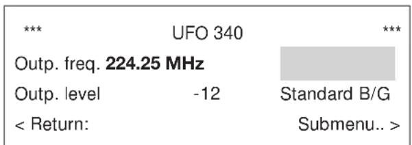
4. Selecting the output frequency or output channel

Main menu
other
| Metric | Value | | :--- | :--- | | ***, **UFO 340 | *** | | Outp. freq. 224.25 MHz | | Outp. level | -12 | | < Return: | Standard B/G Submenu.. > |Submenu output
Can be adjusted in 7 MHz or 8 MHz steps (depending on the standard) between 111.25 MHz and 847.25 MHz with the "+" or "-" key. For standards D/K and I, the channel display for special channels is shown as „----“.
The fine tuning of the output frequency in 250 kHz steps is possible in the submenu of the output frequency. Enter the submenu with the ☐ key, and set the desired frequency with the “+” or “−” key.
Exit the submenu again by pressing the key.
Note:
This setting is only possible, if the channel unit twin A is selected.
The output frequency of the channel unit twin B is determined once the output frequency of the channel unit twin A is set and cannot be adjusted separately: fOutputB = fOutputA + 7 MHz (Standard B).
foutputB = foutputA + 8 MHz (Standard G, D, K, I)
5. Selecting the output level
Twin A 1744 MHz
Outp. Ch12 224.25 MHz
Stereo 7.02/7.20 MHz
Vol 3 Vid 2
AV
***
UFO 340
***
Outp. freq. 224.25 MHz
Outp. level -15 Standard B/G
< Return: Submenu..>
Submenu outputMain menu
The output level can be adjusted in 40 steps with the “+” or “−” key. The adjustment limits are marked with “Min” and “Max” (comparable to the left and right stopping point of a conventional variable attenuator).
The setting of the output level is possible in the submenu of the output frequency. To do this, enter the submenu with the and set the desired level with the “+” or “-” key.
Exit the submenu by pressing the key again.
Note:
The setting is only possible if channel unit twin A is selected. The output level of the channel unit twin B is determined once the output level of the channel unit twin A is set and is practically identical to the set value.
6. Selecting the TV standard
Twin A: 1744 MHz
Outp. Ch12 224.25 MHz
Stereo 7.02/7.20 MHz
Vol 3 Vid 2
AV
***
UFO 340
***
Outp. freq. 224.25 MHz
Outp. level -12 Standard I
< Return: Submenu.. >
Submenu outputMain menu
Select the TV standard in the submenu with the “+” or “-” key on the control unit. The TV standards B/G,D/K and I can be selected. In addition, the standard M can also be set, however, only in the channel plan according to the standard B or G with 4.5 MHz video/audio carrier spacing.
7. Selecting the audio operating mode
Twin A: 1744 MHz
Outp. Ch12 224.25 MHz
Stereo 7.02/7.20 MHz
Vol 3 Vid 2 AV
The operating mode can be changed via the control unit with the “+” or “-” key (Selection “mono,” “stereo,” “dual sound” or “auto”).
In the audio operating mode “mono”, the Sat audio carrier operating mode can be selected (“sub” or “main,” see item 9).
Instructions regarding the operating mode "auto"
●Only use for Sat programmes with VPS signals (data line).
● Representation depends on the contents of the data line "Auto S" (Stereo), "Auto Z" (dual sound), "Auto M" (mono).
- If the VPS signal is missing, automatic switch-over to operating mode “dual sound” is effected (displayed as “Auto*Z”).
●The Sat audio carrier frequencies cannot not be changed in the operating mode "Auto."
For all programmes in German with teletext, the VPS signal is also transmitted. For these programmes, it is recommended to set the operating mode “auto.” Automatic switch-over in the module according to the set operating mode is effected.
Note regarding operating mode "dual sound":
In the operating mode "dual sound", the Sat audio carrier frequencies can be changed in the submenu.
Purpose: Switching between sound 1 and sound 2 for multilingual programmes (e.g. Eurosport).
Twin A: 1744 MHz
Outp. Ch12 224.25 MHz
Dual sound 7.02/7.20 MHz
Vol 3 Vid 2 AV
***
UFO 340
***
Audio carrier swap:
7.20/7.02 MHz
< Return: Submenu.. >
Submenu dual soundMain menu
Note regarding the TV standards:
The processing of the TV accompanying sound is only possible in stereo, if standard B/G is selected.
If another TV standard (D/K, I or M) is selected, the processing of the accompanying sound is effected in mono. If the Sat accompanying sound is in stereo, the processing of the mono signal on the output side is automatically effected per summation ((L+R)/2) from the Sat stereo signal for the setting "stereo" or "auto" ("Auto S").
8. Selecting the Sat audio carrier frequency
Twin A: 1744 MHz
Outp. Ch12 224.25 MHz
Stereo 7.02/7.20 MHz
Vol 3 Vid 2 AV
The second Sat audio carrier frequency has a fixed spacing of 180 kHz to the first carrier in the operating mode “stereo” and “dual sound.”
The Sat audio carrier frequency (5.5 - 9 MHz) can be adjusted via the control unit with the “+” or “-” key.
9. Selecting the Sat audio carrier operating mode
Twin A: 1744 MHz
Outp. Ch12 224.25 MHz
Stereo 7.02 MHz Sub
Vol 3 Vid 2 AV
Switch-over of the operating mode is carried out via the control unit with the "+" or "-" key. Select between:
●Operating mode "Sub" (setting for Panda I subcarrier).
- Operating mode "Main" (setting for main audio carrier, e.g. EUTELSAT).
The setting is only possible in the operating mode “mono.” In the audio operating modes, “stereo,” “dual sound” and “auto,” the operating mode “Sub” is always automatically set.
10. Selecting the volume or the Sat audio carrier deviation
Twin A: 1744 MHz
Outp. Ch12 224.25 MHz
Stereo 7.02/7.20 MHz
Vol 3 Vid 2 AV
Setting is carried out via the control unit with the “+” or “-” key. To correct the volume in the audio operating modes “mono sub,” “stereo,” “dual sound” and “auto:”
"Vol 1" = -6 dB
"Vol 2" = -3 dB
"Vol 3" = 0 dB
"Vol 4" = +3 dB
For matching the Sat audio carrier deviation in the audio operating mode "Main:"
"Vol 1" = 420 kHz
"Vol 2" = 140 kHz
"Vol 3" = 85 kHz
11. Selecting the audio de-emphasis
Twin A: 1744 MHz
Outp. Ch12 224.25 MHz
Stereo 6.65 MHz Main
50 μs Vol 3 Vid 2 AV
This setting is only possible in the Sat audio carrier operating mode "Main:"
The setting can be adjusted via the control unit with the “+” or “-” key (“50μs,” “75μs” or “J17”).
12. Selecting the video deviation
Twin A: 1744 MHz
Outp. Ch12 224.25 MHz
Stereo 7.02/7.20 MHz
Vol 3 Vid 2 AV
The setting can be adjusted via the control unit with the “+” or “-” key.
For adjustment to the following FM deviations:
"Vid 1" = 13.5 MHzp
"Vid 2" = 16 MHzp
"Vid 3" = 20 MHzp
"Vid 4" = 25 MHzp
13. Selecting the video polarity
Twin
A:
1744 MHz
Outp. Ch12 224.25 MHz
Dual sound

Vol 3
Vid 2 AV
Main menu
***
UFO 340
***
Video polarity positive
< Return:
Submenu.. >
Submenu Vid 2
"Negative" (normal) or "positive" (C-band transponder) can be set via the control unit with the "+" or "-" key.
14. Operating mode of the AV or decoder interface
Twin A: 1744 MHz
Outp. Ch12 224.25 MHz
Dual sound 7.02/7.20 MHz
Vol 3 Vid 2 AV
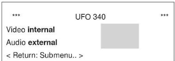
Submenu A/VMain menu
The setting is carried out via the control unit with the “+” or “-” key. The following operating modes are selectable:
● “internal” Video and audio signal are circuited together within the unit. By means of external switching voltages (+12 V), e.g. from a decoder or a video recorder, the decoder interface can be switched over (interruption of the signal path within the unit).
Examples: - Operation with decoder
- Operation with video recorder or video camera
● „external“ Signal path within the unit is interrupted, external breaking voltages have no effect. Intended for A/V signal sources which cannot supply a switching voltage.
Both operating modes can be separately selected for video and audio.
Moreover, the status "Black screen" can be selected for the parameter "video." From version C00 also possible at Twin B. A black screen can be produced from a received Sat TV signal, in order
● to transmit Sat radio signals via a TV channel
● to transmit audio signals fed-in via the A/V interface (e.g. CD-player), via a TV channel
Wiring of the Submin D connector
| Pin | 1 | 2 | 3 | 4 | 5 | 6 | 7 | 8 | 11 | 12 | 13 |
| Signal | Audio input left | Comp. colour input; Video weighted | Video switching signal 0/12 V | Base-band output | Comp. colour output | Audio input right | Audio switching signal 0/12 V | Earth | Earth | Audio output left | Audio output right |
Mixed operation of UFO 340 with UFO 335/365 in older base and extension units
1) For the UFO 340, the upper adjacent channel is already pre-set once the lower channel is selected (forced adjacent channel assignment).
In existing systems, the following situation can occur:
| Channel 7 | Channel 8 | Channel 9 | Channel 10 |
| Occupied with UFO 335 | Should be occupied | Occupied with UFO 335 | Should be occupied |
Solution with UFO 340:
| Channel 7 | Channel 8 | Channel 9 | Channel 10 |
| Occupied with UFO 335 | UFO 340 | UFO 340 | UFO 335 |
One UFO 335 must be reprogrammed from channel 9 to channel 10. If only channel 8 is occupied, the corresponding output signal of the UFO 340 must be disengaged.
2) When extending existing systems (equipped with the power supply unit, order no. 1681794) with UFO 340, take into consideration, that the power supply unit has a reduced power consumption. Please observe the information regarding the power consumption on the sticker on the power supply unit!
Installation
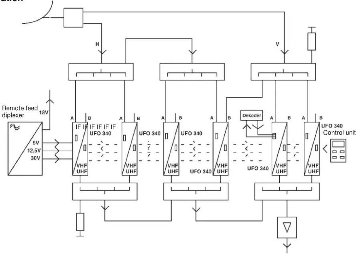
flowchart
graph TD
    A["Remote feed diplexer"] -->|5V/12.5V/30V| B["IF IF UFO 340"]
    B --> C["VHF UHF"]
    C --> D["Control Unit"]
    D --> E["Dekoder"]
    E --> F["UFO 340"]
    F --> G["VHF UHF"]
    G --> H["Control Unit"]
    H --> I["Dedging Valve"]
    I --> J["UFO 340 Control unit"]
    style A fill:#f9f,stroke:#333
    style J fill:#bbf,stroke:#333

flowchart
graph TD
    A["Remote feed diplexer"] -->|5V 12.5V 30V| B["IF IF UFO 340"]
    B --> C["VHF UHF"]
    C --> D["Control unit"]
    D --> E["Dekoder"]
    E --> F["UFO 340"]
    F --> G["VHF UHF"]
    G --> H["Control unit"]
    H --> I["Dedicated Signal"]
    I --> J["Output"]
    K["H"] --> L["Internal Control Unit"]
    L --> M["UFS340"]
    M --> N["Internal Control Unit"]
    N --> O["UFS340"]
    O --> P["Internal Control Unit"]
    P --> Q["UFS340"]
    Q --> R["Internal Control Unit"]
    R --> S["UFS340"]
    S --> T["Internal Control Unit"]
    T --> U["UFS340"]
    U --> V["Control Unit"]
    V --> W["Dedicated Signal"]
    W --> X["Output"]
Freq. sort. 224.25 MHz
Niveau sort. -15 Standard B/G
< Retour: Touche Menu.. >
Freq. sort. 224.25 MHz
Niveau sort. -12 Standard I
< Retour: Touche Menu.. >
Stereo 6.65 MHz Main
50 μs Vol 3 Vid 2 AV
Stereo 7,02/7,20 MHz
Vol 3 Vid 2 AV
Solution with UFO 340:


- UFO® compact Processing System Twin Sat TV channel unit
- CE A
- Setting instructions
- Note: The settings and values shown are just examples and do not necessarily coincide with the delivery status of the unit.
- Selecting the channel unit twin A or twin B
- Note:
- Configuration of the channel units twin A and twin B
- Selecting the input frequency
- Selecting the output frequency or output channel
- Selecting the output level
- Selecting the TV standard
- Selecting the audio operating mode
- Instructions regarding the operating mode "auto"
- Note regarding operating mode "dual sound":
- Note regarding the TV standards:
- Selecting the Sat audio carrier frequency
- Selecting the Sat audio carrier operating mode
- Selecting the volume or the Sat audio carrier deviation
- Selecting the audio de-emphasis
- Selecting the video deviation
- Selecting the video polarity
- Operating mode of the AV or decoder interface
- Mixed operation of UFO 340 with UFO 335/365 in older base and extension units
Brand : KATHREIN
Model : UFO 340
Category : Audio/video converter