
UFO 372/TP - Audio/video converter KATHREIN - Free user manual and instructions
Find the device manual for free UFO 372/TP KATHREIN in PDF.


| Product Type | Audio/Video Converter |
| Brand | Kathrein |
| Model | UFO 372/TP |
| Dimensions (L x W x H) | 120 x 80 x 30 mm |
| Weight | 200 g |
| Power Supply | 5 V DC via USB port (cable included) |
| Power Consumption | 2.5 W max |
| Video Inputs | 1 x HDMI, 1 x VGA |
| Video Outputs | 1 x HDMI, 1 x Composite (RCA) |
| Audio Inputs | 1 x 3.5 mm stereo jack, 1 x stereo RCA |
| Audio Outputs | 1 x 3.5 mm stereo jack, 1 x stereo RCA |
| Supported Resolutions | 480p, 576p, 720p, 1080i, 1080p |
| Supported Audio Formats | PCM, stereo 2.0 |
| Main Functions | Conversion of HDMI signals to VGA and composite, audio extraction, scaling |
| Housing Material | ABS plastic |
| Operating Temperature | 0 °C to 40 °C |
| Operating Humidity | 20% to 80% RH (non-condensing) |
| Maintenance and Cleaning | Unplug the device, clean with a soft dry cloth. Do not use chemicals. |
| Safety | Use only the supplied adapter. Do not expose to moisture or extreme temperatures. |
| Spare Parts and Repairability | Spare parts are not available individually. Contact Kathrein after-sales service. |
| General Information | 2-year warranty. Made in China. |
Frequently Asked Questions - UFO 372/TP KATHREIN
User questions about UFO 372/TP KATHREIN
0 question about this device. Answer the ones you know or ask your own.
Ask a new question about this device
Download the instructions for your Audio/video converter in PDF format for free! Find your manual UFO 372/TP - KATHREIN and take your electronic device back in hand. On this page are published all the documents necessary for the use of your device. UFO 372/TP by KATHREIN.
USER MANUAL UFO 372/TP KATHREIN
- Twin DVB-S-/HDTV channel unit for fi tting in the UFO® compact UFG 3xx base and extension units and UFG 4xx base units
- For processing two DVB-Sat or two HDTV transponders in community antenna networks
- Converts two QPSK-modulated DVB-S signals or two 8PSK-modulated DVB-S2 signals into two QAM-modulated output signals
● The entire channel unit is integrated in a single module - Two inputs A/B, settable via the central controller (e.g. for H/V switching and for generating the cable NIT for two polarisations)
- DiSEqCTM1.0 for controlling external multi-switches
● All essential transmission parameters can be set via the central controller
● The two output channels can be set individually
● The two output levels can be individually adjusted and switched off using the controller - Adjacent channel compatible
- MPEG transport stream processor:
- To set a constant output data rate (stuffi ng) with PCR correction
- With programme fi iter to remove individual TV and radio programmes (easy setting using the USW 30 and UFX 312)
- For NIT matching (cable NIT; additionally UFX 31x required)
- For CAT matching, e.g. to set the operator-ID
● QAM modulator for 16/32/64/128/256 QAM (factory setting: 64 QAM)
● MPEG transport stream processor and QAM modulator as FPGA solution with outstanding values for MER and shoulder attenuation
● Software update available via control interface - Permissible ambient temperature when used in:
- base unit with fan (UFG 412): -20 to +50 °C
- base and extension unit without fan (UFG 3xx): -20 to +40 °C
● Required central controller software version: at least V 9.30
● Dimensions (W x H x D) in mm: 265 x 27 x 170
● Packing unit/weight (pc./kg): 1/0.8

| TypeOrder no. | Frequency range(MHz) | Input level1 | Input data rate | Output data rate3) | Modulation Error Rate MER | Max. output level | Output level setting range | Current consumption | |
| Input 950-21501) | Output 47-100/110-8622) | (dBμV) (MS/s) (MS/s) | (dB) (dBμV) | (dBμV) (V/mA) | |||||
| UFO 372/TP20610084 | Ch Ch | Ch Ch | 55-85 | 2-45 (S1)2-30 (S2) | 2.275-7.15 43 | 91 (QAM 256)85 (QAM 64) | 81-91 (QAM 256)75-85 (QAM 64) | 5/120012.5/76031/7 | |
11 Settable in 1 MHz steps
a Settable in the 8 MHz grid, £ ne tuning on the 250 kHz grid
3 Settable (stuffi ng)
4) If both inputs A and B are connected, take care that the input level is about the same
■ Setup instructions
The twin DVB-S2-QAM (QPSK/8PSK on QAM) transmodulator is set up using the controller on the base unit UFG 404 or UFG 412 or UFG 412/R.
Required software version for the controller: at least version V 9.30
For setup, connect the controller to the module (contains channel units I and II).
The buttons specified below apply to the controller (also see instructions for the base units UFG 404 or UFG 412 or UFG 412/R).
Note: The settings and numerical values shown below are intended as an example and do not necessarily match the delivery status.
The desired channel unit (I or II) is selected using the “<<” or “>>” buttons.
The desired parameter is selected using the "<" and ">" buttons.
The selected parameter flashes in the display.
The setting is performed using the "+" and "-" buttons and where necessary using the "Change setting mode" button.
The sub-menus are activated and deactivated by pressing the "Sub-menu" button.
Finally, press the "M" button to save the setting in the module.
Note: If the controller is disconnected from the module without saving the settings by pressing the "M" button, the settings originally stored in the module are reactivated.
■ Setting the language and interrogating the version numbers
Pressing the "F" button brings you to the System menu, where the language can be set and the version numbers interrogated.

System menu

"Set language" sub-menu
The “+” and “-” buttons in the system menu can be used to choose between “Set language” and “Version numbers”.
Pressing the "Sub-menu" button activates the sub-menu; pressing the "Sub-menu" button again deactivates it.
In the "Set language" sub-menu the "+" and "-" buttons can be used to select the desired language.
The following settings are available: German, English, French or Spanish

System menu
| Boot loader | 4.00 |
| Controller | 9.30 |
"Version numbers" sub-menu
In the "Version numbers" sub-menu the data listed above can be called up.
Then press the "Sub-menu" button to deactivate the sub-menu again. Press the "F" button to exit the system menu again.
The following representation shows the display after plugging in the controller:
Note: An indicator (*) flashes at top right during channel unit initialisation.
| I 1236 MHz | * P TP |
| 27.500 MS/s 3/4 QPSK | |
| Outp. * S21 306.00 MHz | |
| 6.900 MS/s ! | 256 QAM |
Main menu (all symbols shown)
■ Displays
(\*) Left of "TP":
Indicates "desired operating mode not yet reached", displayed continuously in the event of an error. If the indicator (*) is flashing, the channel unit cannot reach its proper operating mode.
This may be because of the following reasons (among others):
- Input frequency or symbol rate set incorrectly
- No input signal
Right of "Outp.":
The channel unit output is switched off.
(!) The exclamation mark indicates that the settings of the output symbol rate and QAM stage are not sufficient for processing the input data rate (i.e. the input data rate is greater than the output data rate).
- without the programme filter, a defective output signal will be output - with the programme filter, the data rate can be sufficiently reduced by filtering out individual programmes.
The exclamation mark indicates here that the user should check the correct operation
(P) Just to the left of „TP“:
The „P“ indicates that the programme filter is activated and that some programmes may be removed from the transponder stream.
If the front end is not clicked into place (no Sat input signal), the following display appears:

Main menu (front end not clicked into place)
The modulation type of the satellite input signal can be seen on the main menu display.
This is always QPSK for operating mode DVB-S1. Both QPSK and 8PSK can apply in mode DVB-S2.
| I | 1236 | MHz | TP | |
| 27.500 | MS/s | 3/4 | QPSK | |
| Outp. | S21 | 306.00 | MHz | |
| 6.900 | MS/s | 256 | QAM |
Main menu (example of DVB-S1)
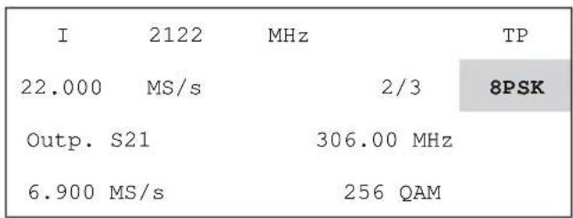
Main menu (example for DVB-S2)
1 Configuring the channel unit
1.1 Selecting the channel unit I or II
The display always refers to one of the two channels processed by the module (I or II).
First select the channel for which you wish to change the settings.
| I | 1236 | MHz | * | TP |
| 27.500 | MS/s | 3/4 | QPSK | |
| Outp. | S21 | 306.00 | MHz | |
| 6.900 | MS/s | 256 | QAM |
Main menu
Pressing the “<<” or “>>” buttons selects “I” or “II”.
1.2 Selecting the input socket
The socket A or B to be used for the input can be selected in the sub-menu for the selected channel unit.
Pressing the "Sub-menu" button ☑ activates the sub-menu; pressing the "Sub-menu" button again deactivates it.
| I | 1236 MHz TP |
| 27.500 MS/s 3/4 QPSK | |
| Outp. S21 306.00 MHz | |
| 6.900 MS/s 256 QAM | |
Main menu
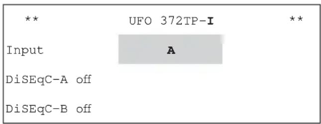
Sub-menu for channel unit I
The following settings are available: A or B
1.3 DiSEqC TM controller
The DiSEqC™ controller for a matrix can be set in the sub-menu for channel unit I.
Pressing the "Sub-menu" button ☑ activates the sub-menu; pressing the "Sub-menu" button again deactivates it.
| I | 1236 MHz TP |
| 27.500 MS/s 3/4 QPSK | |
| Outp. S21 306.00 MHz | |
| 6.900 MS/s 256 QAM | |
Main menu

Sub-menu for channel unit I
Use the “<” or “>” buttons to select DiSEqC-A (DiSEqC level at input socket A) or DiSEqC-B (DiSEqC level at input socket B), and use the “+” and “-” buttons to make adjustments. The following settings are available:
DiSEqC-A or -B off The DiSEqC controller is switched off
Ver-Low-1 In connection with a matrix: Vertical low band position 1
Hor-Low-1 In connection with a matrix: Horizontal low band position 1
Ver-High-1 In connection with a matrix: Vertical high band position 1
Hor-High 1 In connection with a matrix: Horizontal high band position 1
Ver-Low-2 In connection with a matrix: Vertical low band position 2
Hor-Low-2 In connection with a matrix: Horizontal low band position 2
Ver-High-2 In connection with a matrix: Vertical high band position 2
Hor-High 2 In connection with a matrix: Horizontal high band position 2
Note: When the DiSEqC controller is switched on, a DC voltage of approx. 12 V is present at the input sockets! If no matrix is used, the DiSEqC controller cannot be switched on.
The DiSEqC controller can be set up only in the sub-menu for channel unit I.
The selected settings are displayed in the sub-menu for channel unit II only for information - they cannot be selected there.
The DiSEqC settings are applicable to both channel units I and II.
Each of inputs A and B can be plugged into either channel unit.
1.4 Selecting input frequency
The input frequency in the active channel unit is selected using the “<” and “>” buttons. The input frequency can be set continuously from 950 MHz to 2150 MHz in 1 MHz steps using the “+” and “-” buttons.
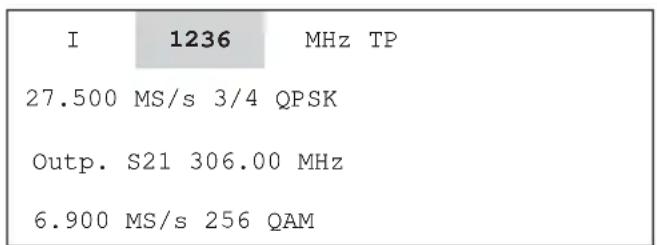
Main menu
| I | 1236 | MHz TP |
| 27.500 MS/s | 9/10 QPSK | |
| Outp. S21 306.00 MHz | ||
| 6.900 MS/s 256 QAM | ||
Main menu (example for digit-by-digit setting)
The setting can also be made on a digit-by-digit basis:
- Press the "Change setting mode" button 🎨 (starts mode)
- The first digit flashes and can be input directly using the buttons on the keyboard
• After the first digit has been input, the second flashes, and so on - To make a correction, press the "Back" button to skip one place to the left
- After the last digit has been set, press the "Change setting mode" button ☐ to end the mode
The current SNR and the automatically detected operating mode, DVB-S or DVB-S2 of the front end are displayed in the input frequency sub-menu.
Pressing the "Sub-menu" button ☐ activates the sub-menu; pressing the "Sub-menu" button again deactivates it.

Main menu

Sub-menu for "Input frequency" (no signal)
The displays of SNR and DVB operating modes are valid only in regular operation with the front end clicked into place.
Note: For the SNR display, all parameters must be set and the indicator (*) must not be flashing.
Trouble-free operation of the systems requires: SNR > 12 dB
1.5 Selecting the input symbol rate
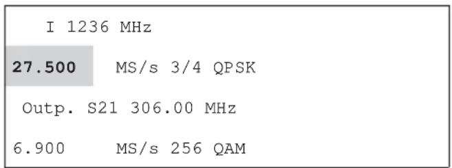
Main menu

Main menu (example for digit-by-digit setting)
The input symbol rate is selected using the "<" and "> " buttons.
The input symbol rate can be adjusted continuously from 2.0 MS/s to 45 MS/s (DVB-S) or 2.0 MS/s to 30 MS/s (DVB-S2) in 0.1 MS/s steps using the "+" and "-" buttons.
The digits can also be entered individually to a resolution of 0.001 MS/s:
- Press the "Change setting mode" button 🎨 (starts mode)
- The first digit flashes and can be input directly using the buttons on the keyboard
• After the first digit has been input, the second flashes, and so on
- To make a correction, press the "Back" button to skip one place to the left
- After the last digit has been set, press the "Change setting mode" button ☐ to end the mode
Note: The code rate (e.g. 3/4) is automatically determined once the channel unit has locked on to the set transponder. If an exclamation mark “!” is displayed for the output symbol rate, the output symbol rate or QAM stage must be changed to ensure proper operation of the unit.
1.6 Selecting output channel or output frequency
The output channel unit is selected using the "<" and "> " buttons. You can use the "+" and "-" buttons to adjust the channel from 48 to 62.25 MHz and 114 to 858 MHz in 7 or 8 MHz increments.
| Inp. | 1568 MHz | ||
| 27.500 | MS/s | 3/4 | TP |
| Outp. | S21 | 306.00 | MHz |
| 6.900 MS/s | 256 QAM | ||
Main menu

"Output frequency" sub-menu
Fine adjustments can be made to the output frequency in the output channel sub-menu in 250-kHz steps.
Pressing the "Sub-menu" button ☑ activates the sub-menu; pressing the "Sub-menu" button again deactivates it.
1.7 Selecting the output level
The output level is selected using the "<" and "> " buttons.

Main menu

"Output frequency" sub-menu
The output signal rate can be adjusted in 40 steps from level maximum ("0") to minimum ("-40") using the output channel sub-menu.
Pressing the "Sub-menu" button ☑ activates the sub-menu; pressing the "Sub-menu" button again deactivates it. The output level is selected using the "<" and ">” buttons and adjusted using the "+" and "-" buttons.
1.8 Switching output on/off
The output channel unit is selected using the "<" and "> " buttons.
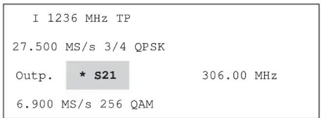
Main menu (output I switched off)
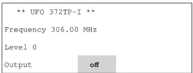
"Output channel" sub-menu
The output can be switched on and off using the output channel sub-menu.
The following settings are available: on or off
Pressing the "Sub-menu" button ☑ activates the sub-menu; pressing the "Sub-menu" button again deactivates it.
The output is selected using the "<" and "> " buttons and adjusted using the "+" and "-" buttons.
When the output is switched off an indicator (*) is shown in the main menu, on the left beside the output channel.
If any channel unit (I or II) is not used, its output signal must be switched off.
1.9 Selecting the output symbol rate
The output symbol rate is selected using the "<" and ">" buttons.

Main menu
The output symbol rate can be adjusted continuously from 2.275 MS/s to 7.150 MS/s in 0.001 MS/s steps using the “+” and “-” buttons.
The digits can also be entered individually to a resolution of 0.001 MS/s:
- Press the "Change setting mode" button 📋 (starts mode)
- The first digit flashes and can be input directly using the buttons on the keyboard
• After the first digit has been input, the second flashes, and so on - To make a correction, press the "Back" button to skip one place to the left
- After the last digit has been set, press the "Change setting mode" button ☐ to end the mode
1.10 Selecting the QAM stage
The output signal QAM stage is selected using the "<" and "> " buttons.
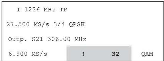
Main menu
Select the desired QAM using the "+" and "-" buttons. QAM stages 16, 32, 64, 128 and 256 are available.
Note: If different QAM stages are available, it is advantageous to select the lower stage (e.g. if 256 and 64 are available, select 64). If an exclamation mark “!” is shown beside the output symbol rate (i.e. the input data rate is too large for the output data rate setting), the output symbol rate or the QAM stage must be increased to ensure correct operation.
1.11 Selecting the modulation signal for the QAM modulator
The modulation signal (mode) for the QAM modulator is selected in the QAM stage sub-menu.
The output signal QAM stage is selected using the "<" and ">" buttons.
Pressing the "Sub-menu" button activates the sub-menu; pressing the "Sub-menu" button again deactivates it.
The QAM mode is selected using the "<" and "> " buttons and adjusted using the "+" and "-" buttons.

Main menu

"QAM stage" sub-menu
The following settings are available:
| Mode | SAT Sig | Normal mode, the satellite input signal is transmodulated. If there is a fault on the input signal, only fill bytes (0xFF) will be modulated |
| PRBS | Test mode. The QAM signal is modulated with the PRBS-23 sequence.Normal mode is unavailable in this setting | |
| CW | Test mode. Sine-wave signal for levelling using simple signal meters.Normal mode is unavailable in this setting |

Main menu (display in PRBS mode)

"QAM stage" sub-menu for setting PRBS)
| Note: | The output symbol rate can be set in PRBS mode.Simple signal meters can be used to measure the output level in CW mode. |

Main menu (display in CW mode)
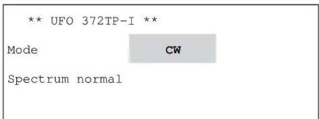
"QAM stage" sub-menu (for setting CW)
1.12 Selecting the position of the output spectrum
The position of the output spectrum can be inverted in the QAM stage sub-menu.
The output signal QAM stage is selected using the "<" and "> " buttons.
Pressing the "Sub-menu" button activates the sub-menu; pressing the "Sub-menu" button again deactivates it.
The output spectrum is selected using the "<" and "> " buttons and adjusted using the "+" and "-" buttons.
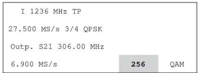
Main menu
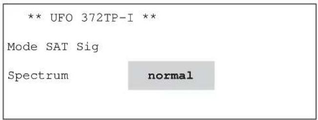
"QAM stage" sub-menu
The following settings are available:
Spectrum normal
The output signal is output in the control position
inverse
The output signal is output with an inverted spectrum
1.13 Transport stream processor: Programme & Iter

Main menu
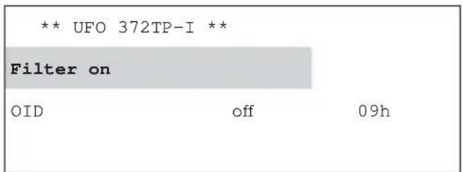
"Transport stream processor" sub-menu
"Filter" programme filter operating mode is selected in the TP (Transport stream processor) sub-menu.
The "TP" transport stream processor is selected with the "<" or "> " buttons and the sub-menu is called up with the "Sub-menu" button.
The "Filter" programme filter is selected with the "<" or "> " buttons and is activated/deactivated with the "+" and "-" buttons.
The settings available are Filter "on" / "off".
This sub-menu can be exited only when the cursor is on the "OID" parameter.
To do this, use the "<" and "> " buttons to select "OID" and press the "Sub-menu" button to return to the main menu.
When Programme filter is set to "on", a "P" appears at the top right of the main menu.

"Transport stream processor" sub-menu

When changing to the "Filter" sub-menu
To process the programming list for the programme filter, the current programme table is read from the transponder pressing the "Sub-menu" button at the "on"/"off" parameter in the programme filter. A progress bar appears whilst this is being done. As soon as the channel unit has successfully determined this information, the sub-menu for adjustment is displayed.

"Filter" sub-menu
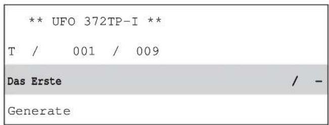
"Filter" sub-menu
The first line shows the type of the programme that was selected, together with the number of the programme and the number of programmes on the transponder.
T=TV programme
R=Radio programme
D=Data service
Programme no. (e.g. 001)
Quantity (e.g. B. 009)
of the selected programme
of the programmes in the transponder
The second line shows the programme name, together with its filter status (+ or -).
The default setting for the status of the programmes that are displayed is “-”, i.e. no programmes are transmitted when the programme filter is switched on, but the programming list is not being processed.
The "Generate" button in the third line starts the compilation of the programme list, that then is effective.
The selection of the programmes carried over is performed using the “+” and “−” buttons, where the status “+” means the programme will be carried over and the status “−” means it will be removed.
The "Status" parameter is selected using the "<" and "> " buttons.
The settings become effective when the filter table has been compiled. This is done using the “<” and “>” buttons; select the “Generate” parameter and use the “+” or “-” buttons to initiate the compilation of the programme table.
Note:
The programme filter can be processed even if it is not activated ("off"). This means that the operation can be checked or temporarily deactivated without waiting times or reprogramming.
If the programming list was not processed but the programme filter was switched on, the previously saved list will be active, or in the absence of any list no programmes will be transmitted.
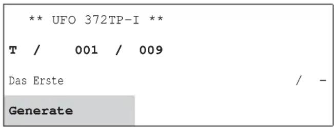
"Filter" sub-menu

On generating the programme filter
The "Programme fi Iter" sub-menu is exited using the "Sub-menu" button.
Note:
If the maximum possible number of programmes carried over is exceeded, an error message appears.
1.14 Transport stream processor: Operator ID
| I 1236 MHz TP | ||
| 27,500 MS/s 3/4 QPSK | ||
| Outp. S21 306.00 MHz | ||
| 6,900 MS/s | 64 | QAM |
Main menu
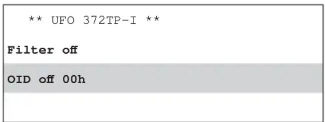
"Transport stream processor" sub-menu
The setting of the Operator ID "OID" is performed in the TP (Transport stream processor) sub-menu.
The "TP" transport stream processor is selected with the "<" or "> " buttons and the sub-menu is called up with the "Sub-menu" button.
The Operator ID function is selected with the “<” or “>” buttons and is activated/deactivated with the “+” and “-” buttons.
The settings available are OID "on" / "off".
The Operator ID can be entered; to do this use the “<” and “>” buttons to select the numeric value and the “+” and “-” to change it correspondingly. The values available are “00h” to “FFh”.
This sub-menu can be exited only when the cursor is on the "OID" parameter.
To do this, use the “<” and “>” buttons to select “OID” and press the “Sub-menu” button to return to the main menu.
2 Settings at system level
Note: The use of the controller bus demultiplexer UFX 314 (BN 20610071) is an essential requirement for making the following settings.
The central controller is selected by pressing the double arrow buttons “<<” and “>>”. The procedure is exactly the same as for the channel units; when selected the controller has the same priority as a channel unit. When the central controller is selected, its LED lights up yellow.
2.1 Setting the language and interrogating the version numbers
Pressing the "F" button brings you to the system menu, where the language can be set and the version numbers interrogated, the system password set and the cable NIT settings made.


Main menu "Set language" sub-menu
The instructions for this can be found at the start of the setup instructions, since these menus are accessible at and relevant to the channel unit level.
2.2 Setting the system password
Use the "+" and "-" buttons to select the "System password" menu item and press the "Sub-menu" button to call it up. The first digit of the PIN flashes and can be input directly using the buttons on the keyboard. Then the next digit flashes, and so on. Correction can be made by pressing the "Back" button.
Exit the "System password" menu by pressing the "Change setting mode" button
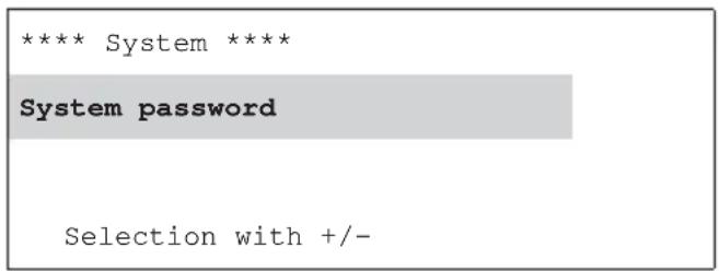

Main menu "System password" sub-menu
2.3 Settings for generating the cable NIT
Pressing the "F" button brings you to the system menu, where the cable NIT settings can be made. Press the "+" and "-" "Cable NIT" buttons in the system menu.
Pressing the "Sub-menu" button ☐ activates the sub-menu; pressing the "Sub-menu" button again deactivates it.


System menu "Cable NIT" sub-menu
Press the "<" and "> " buttons to select the desired parameter "off/on", "Generate", "Name" or "ID". Press the "Sub-menu" button to activate the selected parameter and open the respective sub-menu.
2.3.1 Setting the name and the network ID for the cable NIT
Press the "<" and "> " buttons to select the desired parameter "on", "Generate", "Name" or "ID".
Press the "Sub-menu" button to activate the selected parameter and open the respective sub-menu.
The network name is set by adding “+” or removing “-” characters at the flashing cursor in the third (name) line. The character to be added is selected by using the “<” and “>” buttons to move the cursor within the first two lines. The maximum number of characters is 40.
Exit the menu by pressing the "Sub-menu" button; this saves the set value.
The network ID should only be set if the operator applied for and was granted the ID by the ETSI.
The preset value (FF01) is intended for networks without a specific network ID.
The network ID is selected digit-by-digit using the "<" and "> " buttons and is changed using the "+" and "-" buttons.
Exit the menu by pressing the "Sub-menu" button; this saves the set value.

"Name" sub-menu "ID" sub-menu

2.3.2 Generating the cable NIT, switching the cable NIT on and off
The controller completes the NIT generation process after it is started manually with the "+" button.
The new cable NIT is created and then sent to the channel units (with QAM output). The procedure can be aborted by pressing the “-” button (leading to the error message shown below). A progress bar is displayed in the bottom line of the display during the generation process.
When the cable NIT is complete it is saved and can now be switched on and off as required. This is done by using the "<" and ">” buttons to select the "Cable NIT" "on/off" sub-menu and using the "+" and "-" to make the change-over.
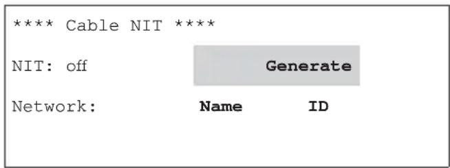
"Cable NIT" sub-menu

"Cable NIT" sub-menu (display during NIT generation)

"Cable NIT" sub-menu (display during abort)

"Cable NIT" sub-menu
The following error messages may appear during cable NIT generation:
| NIT error |
| Not all channel |
| units registered |
| < Further: Button > |
"Cable NIT" sub-menu

"Cable NIT" sub-menu
The following conditions must be fulfilled to generate the NIT successfully:
• The system must be fully set up
- All digital channel units must be in operation with their front ends clicked into place
Note: The NIT compilation cannot be performed if the HF output signal is switched on at an unused channel unit.
2.3.3 Planning a system with cable NIT
When planning a system with cable NIT, the following should be noted regarding the position of the modules:
Case 1: All modules control the functioning of the cable NIT.
In this case the position of the individual modules in the system is immaterial and irrelevant.
Case 2: UFO® compact system made up of different module types
If not all of the modules in use are capable of generating a cable NIT, the insert position specification described below must be complied with.
Insert position speci cation:
For the NIT generation to function properly, each satellite frequency plane must be reached by at least one channel unit that is capable of generating a NIT.
a) Generation with an input distributor row
![graph TD subgraph LeftPanel A1["•e.g. UFO 372/TP"] --> A2["A"] A2 --> A3["•e.g. UFO390"] A3 --> A4["•e.g. UFO390"] A4 --> A5["•e.g. UFO390"] A5 --> A6["•e.g. UFO390"] end subgraph RightPanel B1["•e.g. UFO390"] --> B2["•e.g. UFO390"] B2 --> B3["•/×"] B3 --> B4["•/×"] B4 --> B5["•/×"] B5 --> B6["•/×"]…](/content/2026/06/1263217/images/51300eec10f9f180cea07134e8ecac82b67f7ecb3bf92c03ea3341e5e690c651.jpg)
b) Two polarisations
![graph TD subgraph System A A1["e.g. UFO390"] --> A2["Block"] A3["e.g. UFO390"] --> A4["Block"] A5["e.g. UFO390"] --> A6["Block"] A7["e.g. UFO390"] --> A8["Block"] end subgraph System B B1["e.g. UFO 372TP"] --> B2["Block"] B3["e.g. UFO 390"] --> B4["Block"] B5["e.g. UFO 390"] --> B6["Block"] B7["e.g.…](/content/2026/06/1263217/images/3c306270d338bd205121d5d57d356582995da4f85226a6543f484fcf01dbb012.jpg)
c) Two input distributor rows, several polarisations (with option UFS 340)
![graph TD subgraph_Inputs_A["Input A"] A1["Pin 1: P1237C0-1.9e"] --> A2["to inputs A"] A3["Pin 2: UFO390"] --> A4["to inputs A"] A5["Pin 3: UFO390"] --> A6["to inputs A"] A7["Pin 4: UFO390"] --> A8["to inputs A"] end subgraph_Inputs_B["Input B"] B1["Pin 1: P1237C0-1.9e"] --> B2["to inputs B"] B3["Pin…](/content/2026/06/1263217/images/02bf86b47b7ed7b10b693b0c3e77965ac4e57c42fac2c1bce9abbbb66b8175cd.jpg)
Note:
The cable NIT can be used only on transponders that are fitted with an NIT-capable channel unit.
3 Notes and typical application
When using in older base and expansion units, see following note.
Note:
- When expanding existing systems (still using power supply BN 1681794) with UFO 372/TP, note that the power supply has a lower current rating. Therefore study the power consumption information on the power supply label.
- If it is fitted in the UFG 404 base unit, check that the maximum permissible loading on the power supply unit is not exceeded.
![graph TD PC["PC"] --> Controller_Bus_Demultiplexer_UFX_314["CONTROLLER BUS DEMULTIPLEXER UFX 314"] Controller_Bus_Demultiplexer_UFX_314 --> RF_out["RF output"] RF_out --> Controller["CONTROLLER"] Controller_Bus_Demultiplexer_UFX_314 --> VHF_UHF["VHF UHF"] VHF_UHF --> UFX_314_UFX_314_UFX_314_UFX_314_…](/content/2026/06/1263217/images/344435bfeb7d0e31ec9f0a867739207f8846eb14494e4d39e121c05e0dff01fb.jpg)

Electronic equipment is not household waste - in accordance with directive 2002/96/EC OF THE EUROPEAN PARLIAMENT AND THE COUNCIL of 27th January 2003 on used electrical and electronic equipment, it must be disposed of properly. At the end of its service life, take this unit for disposal to an appropriate official collection point.


Sottomenu del «Nome» Sottomenu della «ID»


- SETUP INSTRUCTIONS
- SETTING THE LANGUAGE AND INTERROGATING THE VERSION NUMBERS
- DISPLAYS
- (\*) LEFT OF "TP
- RIGHT OF "OUTP
- JUST TO THE LEFT OF „TP
- 1 CONFIGURING THE CHANNEL UNIT
- 1.1 SELECTING THE CHANNEL UNIT I OR II
- 1.2 SELECTING THE INPUT SOCKET
- 1.3 DISEQC TM CONTROLLER
- 1.4 SELECTING INPUT FREQUENCY
- 1.5 SELECTING THE INPUT SYMBOL RATE
- 1.6 SELECTING OUTPUT CHANNEL OR OUTPUT FREQUENCY
- 1.7 SELECTING THE OUTPUT LEVEL
- 1.8 SWITCHING OUTPUT ON/OFF
- 1.9 SELECTING THE OUTPUT SYMBOL RATE
- 1.10 SELECTING THE QAM STAGE
- 1.11 SELECTING THE MODULATION SIGNAL FOR THE QAM MODULATOR
- 1.12 SELECTING THE POSITION OF THE OUTPUT SPECTRUM
- 1.13 TRANSPORT STREAM PROCESSOR: PROGRAMME & ITER
- 1.14 TRANSPORT STREAM PROCESSOR: OPERATOR ID
- 2 SETTINGS AT SYSTEM LEVEL
- 2.1 SETTING THE LANGUAGE AND INTERROGATING THE VERSION NUMBERS
- 2.2 SETTING THE SYSTEM PASSWORD
- 2.3 SETTINGS FOR GENERATING THE CABLE NIT
- 2.3.1 SETTING THE NAME AND THE NETWORK ID FOR THE CABLE NIT
- 2.3.2 GENERATING THE CABLE NIT, SWITCHING THE CABLE NIT ON AND OFF
- 2.3.3 PLANNING A SYSTEM WITH CABLE NIT
- INSERT POSITION SPECI CATION
- NOTE
- 3 NOTES AND TYPICAL APPLICATION
Brand : KATHREIN
Model : UFO 372/TP
Category : Audio/video converter