
REV24RF - Thermostat SIEMENS - Free user manual and instructions
Find the device manual for free REV24RF SIEMENS in PDF.


| Product type | Wireless room thermostat |
| Brand | Siemens |
| Model | REV24RF |
| Dimensions (W x H x D) | 85 x 85 x 30 mm |
| Weight | 150 g |
| Power supply | 2 AA batteries (1.5 V) |
| Communication type | Radio frequency (RF) |
| Temperature setting range | 5 °C to 35 °C |
| Accuracy | 0.5 °C |
| Programming | 7 days, 4 time periods per day |
| Display | LCD with backlight |
| Main functions | Day/night mode, frost protection mode, holiday mode, timer, window open detection |
| Maintenance and cleaning | Clean with a soft, dry cloth. Do not use chemical products. |
| Safety | Low battery indicator, frost protection |
| Mounting | On wall base with supplied plugs and screws |
| Protection rating | IP20 |
| Operating temperature | 0 °C to +50 °C |
| Repairability | Batteries replaceable by user. No specific spare parts available. |
Frequently Asked Questions - REV24RF SIEMENS
User questions about REV24RF SIEMENS
0 question about this device. Answer the ones you know or ask your own.
Ask a new question about this device
Download the instructions for your Thermostat in PDF format for free! Find your manual REV24RF - SIEMENS and take your electronic device back in hand. On this page are published all the documents necessary for the use of your device. REV24RF by SIEMENS.
USER MANUAL REV24RF SIEMENS
natural_image
Close-up of a hand using a screwdriver to adjust or install a white plastic enclosure with a small component (no text or symbols visible)
natural_image
Two-step installation of an electrical switch panel, showing hand positioning and mounting mechanism (no text or symbols visible)
natural_image
3D rendering of a white rectangular electronic device with a curved cutout, labeled 'E' in the top-left corner (no other text or symbols)
natural_image
Diagram of a mechanical component with arrows indicating directional movement, no text or symbols present
natural_image
Two views of a battery pack being inserted, showing the left panel with a black arrow and the right panel with a tool (no text or symbols visible)

natural_image
White plastic optical device with internal components and a labeled part 'L' (no text or symbols on the device itself)
natural_image
Diagram of a device with a rotating knob and a dial indicator, mounted on a stand (no text or symbols)
natural_image
White rectangular device with a curved top and circular button, mounted on a black stand with a rotational arrow indicator (no text or symbols)
natural_image
White plastic electrical fuse box with green connectors and a white arrow indicating a component (no text or symbols visible)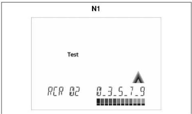
natural_image
Interior view of an electronic device casing with green connectors and mounting holes (no text or symbols visible)


line
| Time | Duration (h) | | :--- | :--- | | 12:00 | 3 min. | | 12:00 | Off | | 12:00 | Off | ④ / 1.1.5 24 h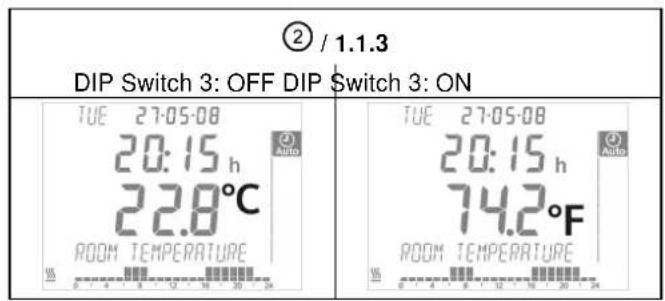

line
| Time (hours) | Temperature (°C) | | ------------ | ---------------- | | -4 | 19 | | -3 | 18 | | -2 | 17 | | -1 | 16 | | P.1 | 20 |
line
| PID Model | Timeframe | Value | | --------------- | ----------------------------- | --------- | | PID self-learning | t | 221216 | | PID 6 | 6 min | - | | PID 6 | 12 min | - | | PID 12 | t | 221216 | | PID 12 | 12 min | - | | t 2-Point | t | - | | t 2-Point | 0.5 °C | - |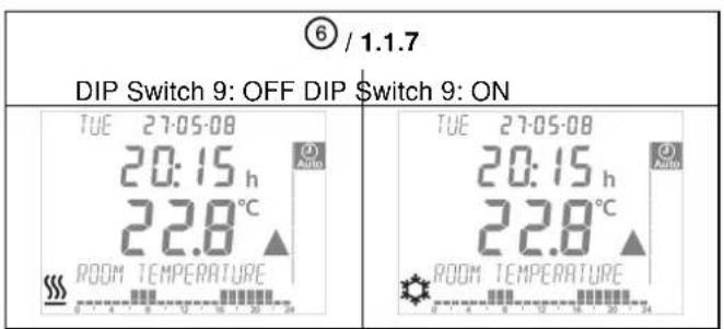


line
| Time (h) | Temperature (°C) | |----------|------------------| | 1h | 19 | | -4 | 18 | | -3 | 17 | | -2 | 18 | | -1 | 18 | | P.1 | 20 |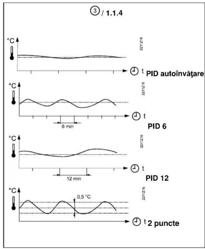
Mounting notes REV24RF.. and RCR10/868
1 Placement of units
1.1 REV24RF.. and RCR10/868
- The units must be placed such that transmitted and received signals will be disturbed as little as possible. For this reason, the following points must be observed with both the REV24RF.. and RCR10/868:
- Do not mount the units on metal surfaces
- Do not mount the units near electrical wires or electronic equipment such as PCs, TV sets, microwave equipment, etc.
- Do not mount the units in the vicinity of large metal structures or other construction elements with fine metal meshes like special glass or special concrete
- The distance between controller / transmitter and receiver must not exceed 20 m or 2 floors
1.2 REV24RF.. (controller / transmitter)
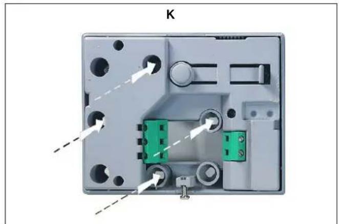
- The controller / transmitter should be mounted in the main living room (wall mounting according to Fig. C, free standing according to Fig. E with stand)
- The REV24RF.. must be located such that it can acquire the room temperature as accurately as possible, without getting affected by direct solar radiation or other heat or refrigeration sources Wall mounting:

1.3 RCR10/868 (receiver)
- The receiver and switching unit should preferably be mounted near the actuating device
- Make certain that the mounting location is dry and protected from splash water
- The unit can be fitted to most commercially available recessed conduit boxes or directly on the wall
2 Checking the wiring
For electrical connections, refer to "Connection diagram".
Note: Do not use stranded wires, only solid wires or stranded wires with ferrules!

3 Notes
• The local regulations for electrical installations must be complied with
- If the reference room is equipped with thermostatic radiator valves, they must be set to their fully open position
• External preliminary protection with max. C 16 A circuit breaker is required in all cases
- If you wish to check the radio link, press the TEST button at the rear of the REV24RF..
- LED_1 is lit red if the RCR10/868 receives very weak or corrupted control telegrams, or no control telegrams at all for about 65 minutes. In this case, check the display of the REV24RF.. to see if there is an error message
- As long as the RCR10/868 receives control telegrams, the receiver works normally. If a control telegram is not correctly received, the relay will maintain the position assumed last.
As soon as the RCR10/868 receives another correct control telegram from the REV24RF..., the receiver continues to work normally
- If, for 60 minutes, the RCR10/868 receives no control telegram, or no correct control telegram, the relay will be deenergized. Hence, the controlled device is switched off. LED_1 is lit red.
As soon as the RCR10/868 receives another correct control telegram from the REV24RF., the receiver continues to work normally
• In the event of a power failure at the RCR10/868, the relay is switched OFF
- Should the REV24RF.. become faulty, the relay of the RCR10/868 can be controlled manually. As soon as the REV24RF.. resumes correct operation, its control telegrams will overwrite the relay's manual control. This process can take up to 130 minutes
- Press override button ⏻ to manually energize and deenergize the relay. LED_1 indicates manual control by blinking at high frequency. LED_2 is lit when Lx-L1 is closed (Lx-L2 open). LED_2 is dark when Lx-L1 is open (Lx-L2 closed)
Commissioning RF set
1 Switching on the REV24RF..
- Remove the black battery transit tab (Fig. F); as soon as the tab is removed, the unit is ready to operate
2 Selecting the language
- When starting up, the display shows the type of controller at top left and "THANK YOU ..." in all available languages on the text line
- Press one of the buttons to stop the running display. The choice of languages starts with "ENGLISH" (factory setting). Press + or - until the language you require appears. Press move the slider to confirm the selected language (also refer to Fig. G)
3 Mounting the RCR10/868 temporarily
- If possible, mount the receiver temporarily (e.g. using double-sided adhesive tape), thus allowing you to find the location with the best reception conditions
- Wire completely the RCR10/868. For steps to be followed, refer to Figs. H through M (close the front also)
4 RCR10/868 and REV24RF..
• The units are supplied interconnected
- For manual connection, refer to operating instructions
5 Mounting and setting up the REV24RF..
• Refer to "Mounting instructions REV24RF.. and RCR10/868"
- Mount or set up the REV24RF.. at your preferred location:
Remove the unit from its baseplate; for procedure, refer to Fig. A
- For wall mounting, refer to Figs. B, C and D
- For setting up, refer to Fig. E
6 Finding the best place for reception
a) Switch on the RCR10/868
b) Set up the REV24RF.. at your preferred location.
Test the radio link by pressing the TEST button at the rear of the controller (refer to Fig. N1)
c) The display of the REV24RF... shows the quality of the radio link. The longer the bar below the numbers 0...9, the better the quality of the radio link. If the bar only appears below number 0, there is no secure radio link (refer to operating instructions)


d) On the receiver, LED_1 indicates the quality of the radio link (refer to Fig. N2):
$$ \begin{array}{l} \text { Red } = \text { insufficient or no connection } \ \text { Orange } = \text { good } \ \text { Green } = \text { very good } \ \end{array} $$
e) If the quality of the radio link is insufficient, reduce the distance between controller and receiver. Then, repeat the test
7 Mounting the RCR10/868 in its final place
a) Switch power off
b) Mark the place where the RCR10/868 is located
c) If necessary, remove wiring
d) Mount the receiver at the place previously identified (refer to H through M), complete wiring and close the housing Figs.
e) Switch power on
Configuration and function check REV24RF..
1 Configuration
1.1 DIP switches
| △ ON / OFF 1 2 | 3 | 4 | 5 | 6 | 7 | 8 | 9 | 10 | See | |||||
| See 1.1.1 | Sensor calibration on | △ | △ | Periodic pump run on | 1.1.5 | |||||||||
| Sensor calibration off Periodic pumprun | off | ▽ | ||||||||||||
| 1.1.2 | Setpoint limitation 16...35 °C | △ | △ | △ | Optimum start control:1 h/°C | 1.1.6 | ||||||||
| Setpoint limitation 3...35 °C | ▽ | △ | ▽ | Optimum start control: 1⁄4 h/°C | ||||||||||
| 1.1.3 | Temperature display °F | △ | ▽ | △ | Optimum start control: 1⁄2 h/°C | |||||||||
| Temperature display °C | ▽ | ▽ | ▽ | Optimum start control: Off | ||||||||||
| 1.1.4 | PID self-learning | △ | △ | △ | (Cooling on) | 1.1.7 | ||||||||
| PID 6 | △ | ▽ | ▽ | (Heating on) | ||||||||||
| PID12 | ▽ | △ | △ | Quartz | 1.1.8 | |||||||||
| 2-Point | ▽ | ▽ | ▽ | Radio clock | ||||||||||
| 1.1.9 | DIP switch resetWhen changing one or several DIP switch positions, a DIP switch reset must be made by pressing the DIP switch reset button (also refer to Fig. 8). Otherwise, the previous settings will be maintained! | 1.1.9 | ||||||||||||
| Note: The factory setting of all DIP switches is ▼OFF | ||||||||||||||
1.1.1 Sensor calibration: DIP switch 1
Set the DIP switch to ON and press the DIP switch reset button:
The display shows CAL. The room temperature currently acquired blinks.
Press + or - to make a recalibration of max. ± 5 °C. To save the entry,
set the DIP switch to OFF and press the DIP switch reset button (also refer to
Fig. ①
1.1.2 Setpoint limitation: DIP switch 2
DIP switch ON: Setpoint limitation 16...35 °C
DIP switch OFF: Setpoint limitation 3...35 °C
(factory setting)
Save the entry by pressing the DIP switch reset button.
1.1.3 Temperature display in °C or °F: DIP switch 3
DIP switch ON: Temperature display in °F
DIP switch OFF: Temperature display in °C
(factory setting)
Save the entry by pressing the DIP switch reset button (also refer to Fig. ②).
1.1.4 Control action: DIP switches 4 and 5
DIP switch 4 ON and 5 ON:
PID self-learning
Adaptive control for all types of application.
DIP switch 4 ON and 5 OFF:
PID 6
For fast controlled systems, applications at locations with temperature variations.
great
DIP switch 4 OFF and 5 ON:
PID 12
For normal controlled systems, applications at locations
with normal temperature variations.
DIP switch 4 OFF and 5 OFF:
2-Point
For difficult controlled systems, 2-position controller with
a switching differential of 0.5 °C (factory setting).
Save the entry by pressing the DIP switch reset button
(also refer to Fig. ③).
1.1.5 Periodic pump run: DIP switch 6
Can only be used when circulating pump or valve is controlled!
This function protects the pump or valve against seizing during longer off periods. Periodic pump run is activated for 3 minutes every 24 hours at 12:00 (display showing symbol ▲).
DIP switch ON:
Periodic pump run on (also refer to Fig.
④)
2 Accessing the expert level
Move the selector slider to the RUN position and press simultaneously + and - for 3 seconds, then release the buttons and, within 3 seconds, press simultaneously ○ and □ for 3 seconds, release □ and keep ○ depressed for another 3 seconds. This enables you to access the expert level for making the settings on that level. Install on display (also refer to Fig. G).
Starting with code 00, the display shows the choice of languages. Navigation on the expert level is made possible with + and -. Confirm the settings by pressing
DIP switch OFF: Periodic pump run off (factory setting)
Save the entry by pressing the DIP switch reset button.
1.1.6 Optimum start control: DIP switches 7 and 8
Optimum start control shifts switch on point P.1 such that the adjusted setpoint will be reached at the required point in time. The setting depends on the type of controlled system, that is, on heat transmission (piping network, radiators), building dynamics (building mass, insulation) and heat output (boiler output, flow temperature)
(also refer to graph in Fig. 5 / 1.1.6).
DIP switch 7 ON and 8 ON: 1 h/°C
For slow controlled systems
DIP switch 7 ON and 8 OFF: 14 h/°C
For fast controlled systems
DIP switch 7 OFF and 8 ON: 12 h/°C
For medium controlled systems
DIP switch 7 OFF and 8 OFF: OFF
Off, no impact (factory setting)
Save the entry by pressing the DIP switch reset button.
Legend to graph in Fig. .⑤.:
t Temperature (°C)
t Forward shift of switch on point (h)
TRx Actual value of room temperature
Pon Start point for optimum start control
1.1.7 Heating or cooling mode: DIP switch 9
DIP switch 9 ON:

Cooling
DIP switch 9 OFF:

Heating mode (factory setting)
Save the entry by pressing the DIP switch reset button
(also refer to Fig. 6).
1.1.8 Radio clock: DIP switch 10
Can only be used if receiver DCF77 is integrated (time signal from Frankfurt)!
DIP switch ON: Clock runs on built-in quartz


DIP switch OFF:


The expert level is quit by pressing the operating mode selection button.
Code list

| Function block | Code | Name | Factory setting | Your setting |
| Basic settings | 00 Language English | |||
| 01 Sensor calibration off | ||||
| 02 Switching differential 0.5 °C | ||||
| LCD settings | 10 Illumination time 10 seconds | |||
| 11 Background brightness 0 | ||||
| 12 Contrast 0 | ||||
| Clock settings | 30 | Time zoneDeviation from time signal received from Frankfurt(Central European Time CET) (refer to Note 1) | 0 hours | |
| 31 | Start of summer time (refer to Note 2) | March 31 (31-03) | ||
| 32 | End of summer time (refer to Note 3) | October 31 (31-10) | ||
Note 1: If the radio clock is not active or not present, this setting has no impact.
With the radio clock active, the time signal received from Frankfurt is shifted by the value set under code 30 (time zone).
Note 2: If the radio clock is not active or not present, the time change always takes place at 02:00 on the Sunday before the set date.
With the radio clock active, the time change is shifted by the value set under code 30 (time zone).
Note 3: If the radio clock is not active or not present, the time change always takes place at 03:00 on the Sunday before the set date.
With the radio clock active, the time change is shifted by the value set under code 30 (time zone).
3 Function check
a) Check the display. If there is no display, check the batteries
b) "Continuously Comfort mode" read the temperature displayed
c) REV.. in heating mode: Set the temperature setpoint to a level above the displayed room temperature (see operating instructions).
REV.. in cooling mode: Set the temperature setpoint to a level below the displayed room temperature (see operating instructions).
d) The relay and thus the actuating device must respond within 1 minute. Symbol ▲ appears on the display. If not:
• Check actuating device and wiring
- In heating mode, the room temperature is possibly higher than the adjusted temperature setpoint, in cooling mode possibly lower
e) Set temperature setpoint of "Continuously Comfort mode" to the required level
f) Select the required operating mode
4 Reset
User-defined settings:
Press simultaneously ○, + and - for 3 seconds:
All temperature and time settings of the slider positions are reset to their default values (refer to section "Factory settings" in the operating instructions). The settings made on the expert level will remain unchanged.
The clock starts at 12:00, the date on 01-01-08
(01 - January - 2008). During the reset time, all sectors of the display are illuminated and can thus be checked.
All user-defined settings plus those made on the expert level:
Press simultaneously the DIP switch reset button, + and - for 5 seconds:
After this reset, all factory settings will be reloaded. This applies to both the slider settings and the settings made on the expert level.
Notes
- The controller is classified as a device of software class A and designed for use in environments with normal degree of pollution
- REV24RF/SET is a set of units consisting of electronic room temperature controller with 7-day time switch, RF transmitter (REV24RF..) and RF receiver (RCR10/868)
Commutateurs DIP 4 ON et 5 ON: PID self-learning
Interruptor PLD 9 ON:

Interruptor PLD 9 OFF:

Interruptor DIP 4 ON e 5 OFF: PID 6
Interruptor DIP 9 ON:

1.2 REV24RF.. (regulator/sender)

- Mounting notes REV24RF.. and RCR10/868
- Placement of units
- REV24RF.. and RCR10/868
- REV24RF.. (controller / transmitter)
- RCR10/868 (receiver)
- Checking the wiring
- Notes
- Commissioning RF set
- Switching on the REV24RF..
- Selecting the language
- Mounting the RCR10/868 temporarily
- RCR10/868 and REV24RF..
- Mounting and setting up the REV24RF..
- Finding the best place for reception
- Mounting the RCR10/868 in its final place
- Configuration and function check REV24RF..
- Configuration
- DIP switches
- Sensor calibration: DIP switch 1
- Setpoint limitation: DIP switch 2
- Temperature display in °C or °F: DIP switch 3
- Control action: DIP switches 4 and 5
- Periodic pump run: DIP switch 6
- Accessing the expert level
- Optimum start control: DIP switches 7 and 8
- Heating or cooling mode: DIP switch 9
- Radio clock: DIP switch 10
- Function check
- Reset
- User-defined settings:
- All user-defined settings plus those made on the expert level:
- Notes
- REV24RF.. (regulator/sender)
Brand : SIEMENS
Model : REV24RF
Category : Thermostat