RAS 180 E - Sander FESTOOL - Free user manual and instructions
Find the device manual for free RAS 180 E FESTOOL in PDF.

User questions about RAS 180 E FESTOOL
0 question about this device. Answer the ones you know or ask your own.
Ask a new question about this device
Download the instructions for your Sander in PDF format for free! Find your manual RAS 180 E - FESTOOL and take your electronic device back in hand. On this page are published all the documents necessary for the use of your device. RAS 180 E by FESTOOL.
USER MANUAL RAS 180 E FESTOOL
natural_image
Close-up of a black and white industrial power tool with meshing and a rotary knob (no visible text or symbols)
text_image
1-2 1-3 1-4 1-5 1 1-1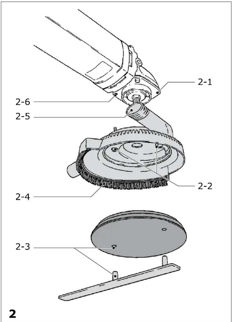
text_image
2-1 2-6 2-5 2-2 2-4 2-3 2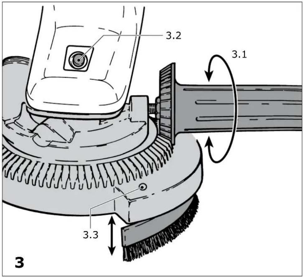
text_image
3.2 3.1 3.3 35 Safety instructions
5.1 General safety instructions
5.2 Machine-related safety instructions
5.3 Emission levels
6 Commissioning
7 Machine settings
7.1 Electronics
7.2 Replacing the brush insert
7.3 Changing sanding pads
7.4 Changing the abrasive
7.5 Dust extraction
8 Working with the machine
9 Service and maintenance
10 Disposal
11 Accessories
12 Warranty
13 Declaration of Conformity
The specified illustrations are at the beginning of this operating manual.
1 Symbols

Warning of general danger

Electric shock

Wear ear protection.

eye protection.

Read the operating instructions/notes
2 Technical data
| Power consumption | 1500 W |
| Rotational speed | 800 – 4000 rpm |
| Tool dia. | 180 mm |
| Spindle thread | M 14 |
| Dust extractor connection diameter | 27 mm |
| Protection class | 回/II |
| Weight | 4.2 kg |
3 Machine features
[1-1] On/off switch
[1-2] Switch-on lock
[1-3] LED
[1-4] Speed control
[1-5] Additional handle
4 Intended use
As specified, the machines are designed for sanding wood, plastic, composite, paintwork, filler, metal and similar materials.
The user bears the responsibility for damage and accidents caused by improper use.
5 Safety instructions
5.1 General safety instructions
WARNING! Read all safety warnings and all instructions. Failure to follow the warnings and instructions may result in electric shock, fi re and/or serious injury.
Save all warnings and instructions for future reference.
The term „power tool“ in the warnings refers to your mains-operated (corded) power tool or battery-operated (cordless) power tool.
- Never allow children to use the machine.
5.2 Machine-related safety instructions
- This power tool is intended to function as a sander. Read all safety warnings, instructions, illustrations and specifications provided with this power tool. Failure to follow all instructions listed below may result in electric shock, fire and/or serious injury.
- Operations such as grinding, wire brushing, polishing or cutting-off are not recommended to be performed with this power tool. Operations for which the power tool was not designed may create a hazard and cause personal injury.
- Do not use accessories which are not specifically designed and recommended by Festool. Just because the accessory can be attached to your power tool, it does not assure safe operation.
- The rated speed of the accessory must be at least equal to the maximum speed marked on the power tool. Accessories running faster than their rated speed can break and fly apart.
- The outside diameter and the thickness of your accessory must be within the capacity rating of your power tool. Incorrectly sized accessories
cannot be adequately guarded or controlled.
- The arbour size of wheels, flanges, backing pads or any other accessory must properly fit the spindle of the power tool. Accessories with arbour holes that do not match the mounting hardware of the power tool will run out of balance, vibrate excessively and may cause loss of control.
- Do not use a damaged accessory. Before each use inspect the accessory such as abrasive wheels for chips and cracks, backing pad for cracks, tear or excess wear, wire brush for loose or cracked wires. If power tool or accessory is dropped, inspect for damage or install an undamaged accessory. After inspecting and installing an accessory, position yourself and bystanders away from the plane of the rotating accessory and run the power tool at maximum no-load speed for one minute. Damaged accessories will normally break apart during this test time.
- Wear personal protective equipment. Depending on application, use face shield, safety goggles or safety glasses. As appropriate, wear dust mask, hearing protectors, gloves and workshop apron capable of stopping small abrasive or workpiece fragments. The eye protection must be capable of stopping fl ying debris generated by various operations. The dust mask or respirator must be capable of fil trating particles generated by your operation. Prolonged exposure to high intensity noise may cause hearing loss.
- Keep bystanders a safe distance away from work area. Anyone entering the work area must wear personal protective equipment. Fragments of workpiece or of a broken accessory may fly away and cause injury beyond immediate area of operation.
- Hold the power tool by insulated gripping surfaces only, when performing an operation where the cutting accessory may contact hidden wiring or its own cord. Cutting accessory contacting a "live" wire may make exposed metal parts of the power tool "live" and shock the operator.
- Position the cord clear of the spinning accessory. If you lose control, the cord may be cut or snagged and your hand or arm may be pulled into the spinning accessory.
- Never lay the power tool down until the accessory has come to a complete stop. The spinning accessory may grab the surface and pull the power tool out of your control.
- Do not run the power tool while carrying it at
your side. Accidental contact with the spinning accessory could snag your clothing, pulling the accessory into your body.
- Regularly clean the power tool's air vents. The motor's fan will draw the dust inside the housing and excessive accumulation of powdered metal may cause electrical hazards.
- Do not operate the power tool near flammable materials. Sparks could ignite these materials.
- Do not use accessories that require liquid coolants. Using water or other liquid coolants may result in electrocution or shock.
Kickback and Related Warnings
Kickback is a sudden reaction to a pinched or snagged rotating wheel, backing pad, brush or any other accessory. Pinching or snagging causes rapid stalling of the rotating accessory which in turn causes the uncontrolled power tool to be forced in the direction opposite of the accessory's rotation at the point of the binding.
For example, if an abrasive wheel is snagged or pinched by the workpiece, the edge of the wheel that is entering into the pinch point can dig into the surface of the material causing the wheel to climb out or kick out. The wheel may either jump toward or away from the operator, depending on direction of the wheel's movement at the point of pinching. Abrasive wheels may also break under these conditions.
Kickback is the result of power tool misuse and/or incorrect operating procedures or conditions and can be avoided by taking proper precautions as given below.
- Maintain a firm grip on the power tool and position your body and arm to allow you to resist kickback forces. Always use auxiliary handle, if provided, for maximum control over kickback or torque reaction during start-up. The operator can control torque reactions or kickback forces, if proper precautions are taken.
- Never place your hand near the rotating accessory. Accessory may kickback over your hand.
- Do not position your body in the area where power tool will move if kickback occurs. Kick-back will propel the tool in direction opposite to the wheel's movement at the point of snagging.
- Use special care when working corners, sharp edges etc. Avoid bouncing and snagging the accessory. Corners, sharp edges or bouncing have a tendency to snag the rotating accessory and cause loss of control or kickback.
- Do not attach a saw chain woodcarving blade or
toothed saw blade. Such blades create frequent kickback and loss of control.
Safety warnings specific for sanding operations
- Do not use excessively oversized sanding disc paper. Follow manufacturers recommendations, when selecting sanding paper. Larger sanding paper extending beyond the sanding pad presents a laceration hazard and may cause snagging, tearing of the disc or kickback.
5.3 Emission levels
Levels determined in accordance with EN 60745 are typically:
Sound pressure level 84 dB(A)
Noise level 95 dB(A)
Measuring uncertainty allowance K = 3 dB


WARNING
The noise produced during work may damage your hearing.
Always use ear protection. ▶
Vibration emission value a_h (vector sum for three directions) and uncertainty K measured in accordance with EN 60745:
| Sanding: | a_h = 3,5 m/s^2 |
| K = 2,0 m/s | 2 |
The emission values specified (vibration, noise) were measured in accordance with the test conditions stipulated in EN 60745 and are intended for machine comparisons. They are also used for making preliminary estimates regarding vibration and noise loads during operation.
The emission values specified refer to the main applications for which the power tool is used. If the electric power tool is used for other applications, with other tools or is not maintained sufficiently prior to operation, however, the vibration and noise load may be higher when the tool is used. Take into account any machine idling times and downtimes to estimate these values more accurately for a specified time period. This may significantly reduce the load during the machine operating period.
6 Commissioning

WARNING
Risk of accident if the machine is operated using unauthorised voltages or frequencies.
- The mains voltage and the frequency of the power source must correspond with the specifications on the machine's name plate.
- In North America, only Festool machines with a voltage specification of 120 V/60 Hz may be used.
The tool is fitted with an on/off switch [1-1] with switch-on lock [1-2] . Press the switch-on lock to release the switch. Pressing and holding the switch-on lock briefly after the machine starts locks the switch while the motor is running. The motor switches off when you press the on/off switch again.
Attaching the additional handle
The additional handle (1-5) can be secured on either the right or left side of the gear head on the rotary sander.
Attaching extraction hood AH-RAS D 180
The extraction hood can only be used in combination with sanding pads STF D 180 and 2F D 180.
▶ Remove the two Allen screws [2-1 and 2-6] from the bearing cover on the machine first of all.
▶ Push the extraction hood onto the machine fl ange and secure the hood with the two Allen screws [2-2].
7 Machine settings


WARNING
Risk of accident, electric shock
▶ Always pull the plug out of the socket before performing any type of work on the machine.
7.1 Electronics
The machine features full-wave electronics with the following features:
Smooth start-up
The electronically controlled smooth start-up ensures that the machine starts up jolt-free.
Speed control
You can regulate the rotational speed steplessly between 800 and 4000 rpm using the adjusting wheel [1-4].
The following table serves as a guideline to help you select the best electronics setting for the working material. The transition between each speed setting is smooth.
| Processed materialWorking procedure | Electronics setting |
| Sanding off dry,cracked paint 6 | |
| Sanding paint that "smears" 2 - 4 | |
| Sanding thin layers of varnish 3 - 5 | |
| Removing anti-fouling coats 3 - 6 | |
| Sanding hard GRP parts 4 - 6 | |
| Sanding thermoplastics 2 - 3 | |
| Sanding wood 6 | |
| Cleaning sandstone, concrete,shuttering material 4 | |
| Removing rust from paintedmetal parts (6) |
() = suitable to a limited extent
Constant speed
The preselected motor speed remains constant through electronic control. This ensures a uniform cutting speed even when under strain.
Overload safety device
In extreme applications, the current consumption may far exceed the permitted nominal value. A "safety coupling" integrated in an electronic overload safety device switches off the motor and prevents it from burning out. Motor operation resumes immediately after the load is relieved.
Temperature cut-out
To protect against overheating (burning out of motor), an electronic temperature monitoring system has been installed. Prior to reaching a critical motor temperature, the safety electronics switches off the motor. After a cooling time of approx. 3-5 minutes, the machine can be operated again at full load. The machine requires less time to cool down when idling.
LED indicator
The rotary sander is fitted with an electronic adjusting wheel and a green and red LED [1-3] . A green lit LED indicates that the rotary sander is operating in normal mode. A red lit LED indicates that the motor is operating at approx. 70% overload. The overload or temperature cut-out switches off the motor if overloaded for longer periods.
However, alternately flashing green and red LEDs indicate that the brushes are completely worn (remaining working hours max. 10 hours). In this case, have an authorised after-sales service workshop replace the carbon brushes the next day. Always replace with special carbon brushes available in pairs otherwise the LED indicators will not work.
7.2 Replacing the brush insert
▶ Insert a screwdriver through the square opening [3-3] to remove the brush insert.
▶ Insert the new brush strip into the groove, adapt the radius by bending slightly and push in firmly until the brush strip is seated on the base of the cover.
The bristles must be inclined towards the outside.
Two different brush inserts are available
- AH-RAS D 180 Poly (replacement for worn insert)
- AH-RAS D 180 Metall (for use with materials that generate sparks)
7.3 Changing sanding pads

WARNING
Risk of injury
- Do not press the spindle stop until the drive spindle comes to a halt.
- Do not switch on the motor when the spindle stop is pressed in.
Sanding pads STF D 180, 2F D 180
Sanding pads STF D 180 and 2F D 180 are fitted with an M14 thread so that the components can be screwed directly onto the drive spindle.
▶ Usually the sanding pad can be unscrewed from the drive spindle by hand after the spindle stop [3-2] is pressed. If the sanding pad cannot be loosened by hand, use the special face pin wrench [2-3].
Always screw the sanding pad onto the drive spindle by hand as this will invariably make disc removal easier.
Sanding pad Elastik D 180
The Elastik D 180 sanding pad is secured to the drive shaft with a clamping nut and tightened with the face pin wrench.
7.4 Changing the abrasive
Stickfi x abrasives
Self-adhesive abrasives, such as Stickfi x sandpaper and sanding cloths can be affixed to the Stickfi x sanding pad STF D 180. The abrasives are simply
pressed onto the sanding pad and removed after use.
Note
▶ Only use sanding pads if the Stickfix adhesive coating is undamaged.
Before using, check whether the burr layer has not been damaged (e.g. melted) due to improper use.
Fiberfi x abrasives
Fiberfi x abrasives can be used on 2F D 180 and Elastik D 180 sanding pads. Extraction hood AH-RAS D 180 can be used in combination with sanding pad 2F D 180 and Fiberfi x abrasives.
7.5 Dust extraction


CAUTION
Breathing in dust damages the respiratory passage.
- Always connect the machine to a dust extractor.
- When performing work that generates dust, always wear a dust mask.
You can connect a Festool extractor to the extractor connector [2-5]. The extractor hose in the Festool extractor is 27 mm in diameter.
You can adapt the brush ring [2-4] to the respective working position using the additional rotary hand grip [3-1] .
Always turn the brush ring in the direction of dust discharge.
8 Working with the machine
Hold the machine with two hands, one on the motor housing and one on the gear head or additional handle to ensure safe guidance. Do not overload the machine by pressing with excessive force! The best sanding results are achieved with moderate application pressure. The sanding capacity and quality are mainly dependent on the selection of the correct abrasive.
9 Service and maintenance


WARNING
Risk of accident, electric shock
- Always pull the plug out of the socket before performing any type of work on the machine.
- All maintenance and repair work which requires the housing to be opened must only be carried out by an authorised service workshop.
To ensure constant air circulation, always keep the ventilation openings clean and free of blockages. The machine is equipped with self-disconnecting special carbon brushes. If they are worn, power is interrupted automatically and the machine comes to a standstill (see Chapter "Electronics").
10 Disposal
Do not throw the power tool in your household waste! Dispose of the machine, accessories and packaging at an environmentally responsible recycling centre! Observe the valid national regulations.
EU only: European Directive 2002/96/EC stipulate that used electric power tools must be collected separately and disposed of at an environmentally responsible recycling centre.
11 Accessories
Use only original Festool accessories and Festool consumable material intended for this machine because these components are designed specifically for the machine. Using accessories and consumable material from other suppliers will most likely affect the quality of your working results and limit any warranty claims.
Machine wear or your own personal workload may increase depending on the application. Protect yourself and your machine, and preserve your warranty claims by always using original Festool accessories and Festool consumable material!
The order numbers of the accessories and tools can be found in the Festool catalogue or on the Internet under "www.festool.com".
12 Warranty
For our tools, we give warranty for material and production defects in accordance with the locally applicable legal provisions, but in any case for at least 12 months. Within the EU member states, the warranty period is 24 months (verification through invoice or delivery note). Damage caused by the operator, natural wear, overloading, incorrect handling or through the use of the equipment not specified in the operating manual, or damage which was known at the time of purchase, is not covered by the warranty. Furthermore, damage caused by the use of non-original Festool accessories and consumable material (e.g. sanding pads) is also excluded. Complaints can only be recognised if the tool is returned while still assembled to the supplier or an authorised Festool Customer Service workshop. Keep the operating manual, safety instructions, spare parts list and purchase receipt in a safe place. Otherwise the respective, current warranty conditions of the manufacturer shall apply.
Note
Due to continuous research and development work, we reserve the right to make changes to the technical content of this documentation.
13 Declaration of Conformity
Rotary sander Serial no.
RAS 180.03 E-AH 495350
Year of CE mark 2003
We declare under sole responsibility that this product complies with the following norms or normative documents:
EN 60745-1, EN 60745-2-3, EN 55014-1, EN 55014-2, EN 61000-3-2, EN 61000-3-3 in accordance with the regulations stipulated in Directives 98/37/EC (until 28 Dec. 2009), 2006/42/EC (from 29 Dec. 2009), 2004/108/EC.
ppa. Dr. Johann Stainel
Head of Research, Development and Technical Documentation
CE Festool GmbH
Wertstr. 20
D-73240 Wendlingen
REACH for Festool products, their accessories and consumables
REACH is a European Chemical Directive that came into effect in 2007. As “downstream users” and product manufacturers, we are aware of our duty to provide our customers with information. We have set up the following website to keep you updated with all the latest news and provide you with information on all the materials used in our existing products: www.festool.com/reach