Inventa 100 - Sewing machine TERMOZETA - Free user manual and instructions
Find the device manual for free Inventa 100 TERMOZETA in PDF.

User questions about Inventa 100 TERMOZETA
0 question about this device. Answer the ones you know or ask your own.
Ask a new question about this device
Download the instructions for your Sewing machine in PDF format for free! Find your manual Inventa 100 - TERMOZETA and take your electronic device back in hand. On this page are published all the documents necessary for the use of your device. Inventa 100 by TERMOZETA.
USER MANUAL Inventa 100 TERMOZETA
text_image
TERMOZETA®
Inventa 100
natural_image
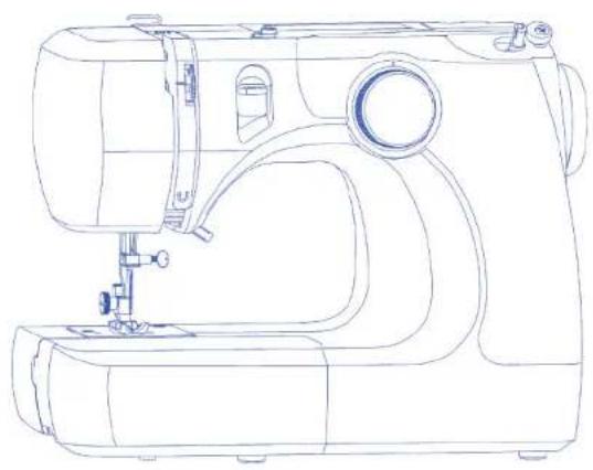
Line drawing of a sewing machine with handle, spout, and buttons (no text or labels)LIBRETTO ISTRUZIONI
▶ INSTRUCTION MANUAL
MODE D'EMPLOI
LIBRO DE INSTRUCCIONES
TERMOZETA®
ITALIANO
text_image
Diagram showing five labeled parts of a mechanical or electrical component, including rollers, tools, and a pencil.text_image
Diagram of a device connection setup with labeled components including power source, cable, and terminal block
text_image
Technical diagram of a sewing machine with numbered parts and directional arrows indicating motion or assembly.text_image
Technical diagram showing a mechanical assembly with numbered components, likely illustrating a turning or cutting process.Piano estraibile
text_image
Diagram of a medical or laboratory procedure with labeled parts including a tool, tubing, and a probe.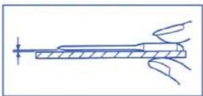
natural_image
Pure technical line drawing of a mechanical component without any text, numbers, or symbolsnatural_image
Line drawing of a sewing machine needle and base with a hand operating the mechanism (no text or symbols)
text_image
Technical diagram showing a mechanical assembly with labeled parts, including a crown and three numbered components.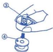
text_image
Diagram showing a hand holding a small mechanical component with numbered parts labeled ③ and ④.Avvolgimento bobina
text_image
Technical diagram of a mechanical assembly with numbered components and exploded views5

6


text_image
Technical diagram of a mechanical device with numbered components and directional arrows indicating movement or assembly.1
2

3
4 5
text_image
Diagram illustrating a mechanical or robotic manipulation process with labeled parts and directional arrowsnatural_image
Technical line drawing of a sewing machine with no visible text or symbolstext_image
Technical diagram of a mechanical assembly with numbered components and a magnified view showing measurement markings.text_image
Technical diagram of a sewing machine with labeled parts and a hand pointing to the base parttext_image
Technical diagram showing a mechanical assembly with numbered components and an arrow indicating direction, alongside a separate labeled scale.Tensione eccessiva
natural_image
Line drawing of a sewing machine needle and base (no text or symbols)text_image
Technical diagram showing labeled components of a mechanical component with numbered parts and a directional arrow indicating motion.natural_image
Illustration of a person using a cart with motion lines and a magnified inset showing hand positioning (no text or symbols)Iniziare a cucire
natural_image
Diagram of a sewing machine needle stitching a fabric, with no visible text or symbolsnatural_image
Technical line drawing of a sewing machine with an inset close-up showing a detail (no text or symbols)natural_image
Line drawing of a sewing machine needle and chain (no text or symbols)natural_image
Line drawing of a sewing machine stitching a piece, with an inset showing the same mechanical component (no text or symbols)NOTA:
text_image
Technical diagram showing three-step sewing process with labeled steps and corresponding fabric pieces▶ PARAGRAFO 4. PUNTI DECORATIVI

text_image
Technical diagram showing three-step assembly steps of a mechanical device with labeled componentstext_image
Technical diagram of a mechanical device with labeled parts (A) and (B), showing spring assembly steps.text_image
Technical diagram of a sewing machine with labeled parts and two views of the base3

▶ Occhiello a coste
text_image
Technical diagram of a mechanical assembly with numbered components and directional arrows indicating motion or assembly.natural_image
Technical line drawing of a mechanical assembly with no visible text or symbols
▶ SAFETY REQUIREMENT

- This booklet is an integral part of the appliance and must be carefully read before use, since it provides important information on the installation, safety, use and maintenance of the appliance. Keep in a safe place.
• After removing the packaging make sure the appliance is undamaged and that no parts ng. If in doubt, do not use and contact an authorised Termozeta service centre.
- Do not leave parts of packaging (plastic bags, foam polystyrene, nails, etc) within reach of children or unqualified persons since they are potential sources of danger.
- If the appliance comes with an earth plug, the electrical safety is ensured only when this plug is correctly connected to an effective earthing system in compliance with the existing electrical safety standards. Termozeta shall not be held responsible for any damages caused by the lack of a correct earthing system.
- Before connecting the plug to the power outlet check that the operating voltage of the appliance corresponds to the voltage of your mains supply. If in doubt, contact a qualified technician.
- Do not use adaptors, multiple plugs and extension leads. If necessary, only use devices that conform to the current safety standards making sure they are compatible with the power of the appliance. If in doubt, contact a qualified technician.
- Any installation not conforming to the above instructions may compromise your safety and cancel the guarantee.
• The machine is exclusively for domestic use for sewing fabrics. - For safety reasons:
- do not use the appliance with bare feet and with wet hands or feet - do not use the appliance outside the home
- do not leave the appliance exposed to atmospheric agents (sun, rain...)
- do not allow the machine to be used by children or by anyone with reduced physical or mental abilities or without experience unless they are supervised and instructed on its use.
- never pull on the power cord or on the appliance itself to disconnect the plug from the power outlet - do not leave the appliance unattended when it is plugged into the main power supply - never immerse the appliance in water or other liquids.
- The power cord of the appliance must not be replaced by the user. If necessary, contact an authorised TERMOZETA service centre or qualified technician.
- Switch off and do not tamper with the appliance should it breakdown and/or not function properly. Contact an authorised TERMOZETA service centre for any repairs and ask for original spare parts.
- Make the appliance unserviceable at the end of its running life by unplugging it from the power outlet and cutting the power cord. Abide by the existing standards in your country for instructions on its disposal.
- Termozeta cannot be held responsible for any damages to people animals or things caused by incorrect installation or due to improper, incorrect or negligent use.
- Do not put fingers near the moving parts. Pay particular attention to the area around the sewing machine needle.
• Always use the correct needle plate otherwise the needle could break. - Do not use bent needles.
- Do not push or pull the fabric during sewing. The needle could bend and break.
- Switch off the sewing machine ("0") whenever any adjustments have to be made in the needle area, e.g. change needle, thread a bobbin or change the foot etc.

INDEX
▶ SECTION 1. NAMES OF PARTS
Names of Parts pag. 14
Connecting machine to power supply pag. 14
Reverse stitch control pag. 14
Presser foot lifter pag. 14
Changing presser foot pag. 15
Extension table
Stitch selector
Changing needle pag. 15
Selecting needle and thread
Bobbin winding
. Removing bobbin case
Threading the machine
Threading the machine
Drawing up bobbin thread
Adjusting the needle thread tension
. Balanced tension
. Tension is too tight
. Tension is too loose
▶ SECTION 3. BASIC SEWING
| Straight stitch | pag. 19 |
| Turn a square corner | pag. 19 |
| Basic zigzag | pag. 19 |
| Overcasting stitch | pag. 19 |
| Multiple zigzag stitch | pag. 19 |
| Blind hem stitch | pag. 20 |
▶ SECTION 4. DECORATIVE STITCHES
| Shell tuck | pag. 20 |
| SECTION 5. BUTTONHOLES | |
| Buttonhole | pag. 20 |
| Corded buttonhole | pag. 21 |
▶ SECTION 6. CARE OF YOUR MACHINE
| Clearing the feed dog | pag. 21 |
| Clearing the hook race area | pag. 21 |
| Replacing the light bulb | pag. 22 |
| Troubleshooting | pag. 22 |
▶ ENGLISH
▶ SECTION 1. NAMES OF PARTS

Names of Parts
① Stitch selector
② Bobbin winder stopper
③ Bobbin winder spindle
④ Bobbin winding tension disk
⑤ Thread take-up lever
⑥ Upper thread guide
⑦ Thread tension dial
⑧ Needle
⑨ Needle plate
⑩ Extension table
⑪ Presser fool
⑫ Reverse stitch control
⑬ Carrying handle
⑭ Spool pin
⑮ Handwheel
⑯ Power switch
⑰ Machine socket
⑯ Free-arm
⑲ Presser foot lifter
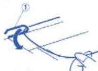
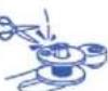
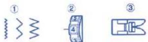
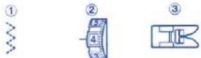
Standard Accessories
① Bobbin
② Seam ripper
③ Felt
④ Sliding buttonhole foot
⑤ Need le set
▶ SECTION 2. GETTING READY TO SEW
text_image
Diagram of a device connection setup with labeled parts including power supply, cable, and terminal block
text_image
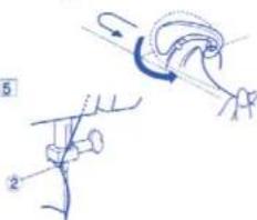
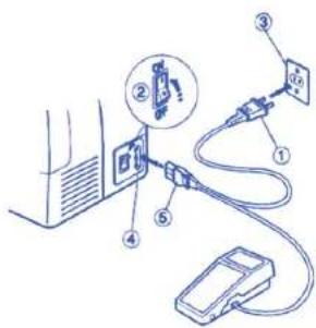
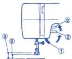
Technical diagram of a sewing machine with numbered parts and directional arrows indicating motion or assembly.Connecting Machine to Power Supply
① Power supply plug
② Power switch (1 / 0)
③ Outlet
④ Machine socket
⑥ Machine plug
Before connecting the power cord, make sure the voltage and the frequency shown on the machine conform to your electrical power.
- Turn off the power switch.
- Insert the machine plug into the machine socket.
- Insert the power supply into the power outlet.
- Turn on the power switch to turn on the power and sewing light.
Caution:
This appliance has a polarized plug (one blade is wider than the other). To reduce the risk of electric shock, this plug will fit in a polarized outlet only one way. If the plug does not fit fully in the outlet, reverse the plug. If it still does not fit, contact a qualified electrician. Do not modify the plug in any way.
▶ Reverse stitch sewing
Press down on the reverse sewing lever and the machine will start sewing reverse.
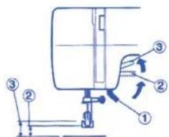
Presser Foot Lifter
① Presser Foot Lifter
② Normal up position
① Highest position
The presser foot lifter raises and lowers the presser foot.
You can raise it about 0.6 cm higher than the normal up position for easy removal of the presser foot or to allow you to place heavy fabric under the presser foot.
ENGLISH
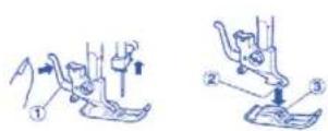
▶ Changing the Presser Foot
① Lever
② Groove
③ Pin
To remove
Turn the handwheel towards you to raise the needle to its highest position. Raise the presser foot. Press the presser foot release lever on the back of the foot holder. The presser foot will drop.
To attach
Place the new presser foot so that the pin on the top of the foot lines up directly below the groove of the foot holder. Lower the foot holder to lock the foot in place.

text_image
Technical diagram showing a mechanical assembly with numbered components and directional arrows indicating motion or force.Extension table
To detach the extension table
Pull the extension table away from the sewing machine. Use the free-arm for sewing cuffs and sleeves. You can use the extension table as a storage container to store all of the accessories.
To attach the extension table
Push the extension in until it snaps into place.
① Extension table
② Tab
① Hole
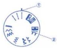
▶ Choosing your stitch pattern
① Stitch selector reference
② Stitch selector
Raise the needle above the fabric.
Turn the stitch selector dial to the desired stitch pattern.
NOTE:
To avoid damaging the needle or your fabric, make sure that the needle is up and out of the fabric before selecting a stitch.

text_image
Diagram of a medical or laboratory device with numbered parts labeled ①, ②, and ③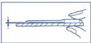
natural_image
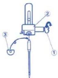
Pure technical line drawing of a mechanical component without any text, numbers, or symbols▶ Changing the needle
① Needle clamp screw
② Needle clamp
③ Flat side
Turn the power switch to the "O" (Off) position before inserting or removing the needle.
Raise the needle to its highest position by turning the handwheel counterclockwise.
Loosen the needle clamp screw (a) by turning it counterclockwise. Remove the needle from the needle clamp.
Insert a new needle into the needle clamp making sure that the flat side of the needle is facing away from you. When inserting the needle into the needle clamp, push it up as far as it will go. Tighten the needle clamp screw firmly by turning it clockwise.
To check if a needle is bent, place the flat side of the needle onto a flat surface (i.e. needle plate or glass). The gap between the needle and the flat surface should be consistent. Never use a bent or blunt needle because a damaged needle can cause permanent snags or runs in knits, fine silks and silk-like fabrics.
| Selecting needle and threadFabric Thread Needle | |||
| Light Weight Crepe de Chine 80 to 100 fine silk 9 (65)Volle, Lawn, 80 to 100 fine cotton orOrgandy, 80 to 100 fine polyester 11 (75)Georgette, Tricot 50 Silk | |||
| Medium Weight | Linen, Cotton | 60 to 80 cotton | 11 (65) |
| Piqué, Serge, | 50 to 80 Ssynthetic | or | |
| Double Knit | Cotton covered polyester | 14 (90) | |
| Percalle | 50 cotton | 14 (90) | |
| Heavy Weight | Denim, Tweed, | 50 silk | |
| Gabardine, | 40 to 50 cotton | 14 (90) | |
| Coating, | 40 to 50 synthetic | or | |
| Drapery and Upholstery | Cotton covered polyester | 16 (100) | |
| Fabric, Canvas | 30 silk | ||
For general sewing, use needle size 11 or 14. A fine thread and needle should be used for sewing lightweight fabrics so that the fabric will not crinkle. Heavy fabrics require a needle large enough to pierce the fabric without fraying the fabric.
▶ ENGLISH
text_image
Diagram showing a sewing machine needle stitching fabric, with labeled component '①' indicating the mechanism.
text_image
Technical diagram showing a mechanical assembly with labeled parts, including a crown and three numbered components.
text_image
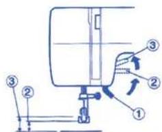
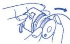
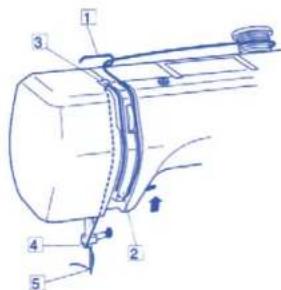
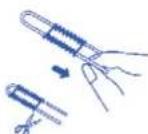
Diagram showing a mechanical assembly with numbered parts, likely illustrating a turning or disassembly process.Bobbin Winding
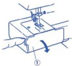
To remove the bobbin case
Remove the extension table from the sewing machine by pulling it to the left. Open the shuttle cover by pulling down the tab that is on the left side of the cover. Raise the needle to its highest position by turning the handwheel towards you.
① Shuttle cover
Hold the bobbin case by the hinged latch and pull the bobbin case straight out of the shuttle.
Bobbin case
③ Hinged latch
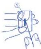
To remove the bobbin
Release the latch of the bobbin case and the bobbin will drop out as illustrated on the left.
Bobbin
text_image
Technical diagram of a mechanical assembly with numbered components and exploded views5

6

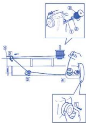
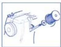
To wind the bobbin
The spool pin is used to hold the spool of thread in order to feed the thread to the machine. The spool pin is found in the back of the sewing machine.
To use:
① Spool pin
② Felt
② Spool of thread
1 Release the clutch by pulling the handwheel out. This will stop the needle from moving while you wind the bobbin.
② Pull the thread from the spool and guide the thread around the thread guide.
④ Thread guide
3 Pass the thread between the tension disks. Thread the bobbin by passing the thread through the hole in the bobbin from the inside to the outside.
4 Wind the thread a few times by hand around the empty bobbin in a clockwise direction.
5 Push the bobbin winder spindle to the right.
6 Press the foot control gently to wind the bobbin. The machine will stop automatically when it is full. Return the bobbin winder spindle to its original position by pushing it to the left and cut the thread.
7 Push the handwheel in to engage the clutch. The sewing machine will not function if the clutch is not engaged. Return the bobbin winder spindle to its original position by pushing it to the left and cut the thread.
8 Push the handwheel in to engage the clutch. The sewing machine will not function if the clutch is not engaged.

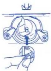
To insert the bobbin
[1] Place the bobbin (a) into the bobbin case making sure that the thread feeds clockwise from the bobbin.
②Draw the thread through the bobbin case slot.
[3]Draw the thread under the tension spring and into the delivery eye. Pull out about 10 cm of thread. ① Tension spring
4 Holding the bobbin case from the latch, position the bobbin case into the shuttle and then release the latch. The case should lock into place when the latch is released.
▶ Threading the upper thread
Threading the upper thread
- Place a spool of thread on the spool pin with the thread coming off in a clockwise direction
- Raise the thread take up lever to its highest position by turning the handwheel counterclockwise.
- Raise the presser foot.
text_image
Technical diagram of a mechanical device with numbered components and directional arrows indicating movement or assembly.1

2
3
4 5

text_image
Diagram illustrating a mechanical or robotic manipulation process with labeled parts and directional arrows①Draw the end of the thread around the thread guide
① Thread guide
②While holding the thread near the spool, draw the end of the thread down along the right channel and around the bottom of the guide plate.
③ Firmly draw the thread up along the left channel and slip the thread into the slit of the thread take up lever from right to left and down into the take up lever eye.
④ Slide the thread behind the needle bar thread guide on the left.
② Needle bar thread guide
5 Thread the needle from front to back.
▶ ENGLISH
1
natural_image
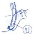
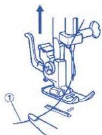
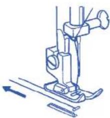
Technical line drawing of a sewing machine with no visible text or symbolsDrawing up the bobbin thread
1 Raise the presser foot and hold the needle thread
① Needle thread
2
text_image
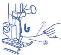
Technical diagram of a sewing machine with labeled parts and a hand pointing to the base2 Bring the bobbin thread up by pulling the needle
Thread ② Bobbin thread
3
natural_image
Line drawing of a sewing machine needle and base (no text or symbols)3 Pull about 15 cm of both threads back and under the presser foot
text_image
Technical diagram of a mechanical assembly with numbered components and a magnified view showing a scale.- Adjusting the needle thread tension
Balanced tension
The ideal straight stitch has threads locked between
two layers of fabric as shown
① Needle thread (top thread)
② Bobbin thread (under thread)
Right side (top side) of fabric
④ Wrong side (under side) of fabric
To adjust the tension, turn the tension dial up to loose and down to lighten.
To loosen
⑥ To tighten
The tension requires adjustment depending on:
- Stiffness and thickness of fabric
- Number of fabric layers
- Type of stitch
text_image
Diagram showing a mechanical assembly with numbered components and an arrow indicating direction, alongside a separate labeled component.Tension is too tight:
① Needle thread (top thread)
② Bobbin thread (under thread)
① Right side (top side) of fabric
② Wrong side (under side) of fabric
To loosen
If the bobbin thread shows through on the right side (top side) of the fabric, turn the tension dial to a lower tension setting to loosen the needle thread tension.

text_image
Technical diagram showing labeled components of a mechanical or electronic component with numbered parts and an arrow indicating direction.Tension is too loose
① Needle thread (top thread)
② Bobbin thread (under thread)
Right side (top side) of fabric
④ Wrong side (under side) of fabric
⑥ To tighten
If the needle thread shows through on the wrong side (under side) of the fabric, turn the tension dial to a higher tension setting to tighten the needle thread.
▶ SECTION 3. BASIC SEWING


▶ Straight stitch sewing
① Stitch selector: 1-3
2 Needle thread tension: from 2 to 6
③ Presser foot: All purpose foot

natural_image
Illustration of a sewing machine with a close-up inset showing the base (no text or symbols)Select the straight stitch
Raise the presser foot and position the fabric next to a seam guide line on the needle plate.
Turn the handwheel to lower the needle to the point where you want to start sewing.
Lower the presser foot and pull the threads to the back. Depress the foot control and gently guide the fabric along the seam guide line letting the fabric feed naturally.
NOTE: 1,6 cm seam allowance is most common.
Securing a seam
To fasten the beginning of a seam, press the reverse stitch lever and sew several reverse stitches first and then release the reverse stitch lever and start sewing forwards. At the end of the seam, repeat the process again.
Turning a square corners
The coner guide is useful to maintain 1.6 cm dseam allowance when turing a square corner.
- Stop stiching when the front edge of the fabric reaches the cornering guide lines.
- Lower the needle turning the handwheel counterclockwise.
- Raise the presser foot and turn the fabric counterclockwise 90°.
- Lower the presser foot and continue sewing in the new direction.
Finish sewing a seam
To fasten the ends of a seam, press the reverse stitch lever and sew several reverse stitches. Raise the foot control and remove the fabric.
ENGLISH
▶ Basic Zigzag
① Stitch selector: 4-6
② Needle thread tension: from 2 to 5
③ Presser foot: All purpose foot
The zigzag stitch is another stitch that is very versatile. It can be a utility stitch for sewing a button, making a buttonhole, hemming, overcasting, mending and darning. It can also be used to decorate with trims, appliques and cut work, or as a decorative stitch.


Overcasting Stitch
① Stitch selector: 6
② Needle thread tension: from 1 to 4
① Presser foot: All purpose foot
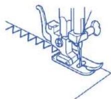
natural_image
Line drawing of a sewing machine needle and base (no text or symbols)This stitch is useful in garment construction and in finishing raw edges of any sewing project. Start overcasting from about 0.3 cm inside the raw corner of a seam. The right tip of the stitch should just clear the seam edge.
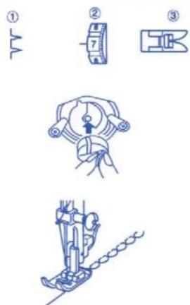
▶ Multiple zigzag stitch
① Stitch selector: 7
② Needle thread tension: from 1 to 4
③ Presser foot: All purpose foot
This stitch is used to finish the seam allowance on synthetics and other fabrics that tend to pucker. Place your fabric to allow a 1.6 cm seam. Trim the seam allowance after sewing.
NOTA:
Be careful not to cut the stitches when trimming the seam allowance
It is also handy for darning and mending.
▶ ENGLISH

Blind Hem Stitch
① Stitch selector: 8 o 9
② Needle thread tension: from 1 to 4
③ Presser foot: All purpose foot
On heavyweight fabrics that ravel, the raw edge should be overcast first. Fold the fabric along the desired edge of the hem, leaving 0.7 cm of the hem edge showing
Raise the presser foot and position the fabric so that the needle is at its left most position just pierces the edge of the fold.
After hemming is completed, press together both sides of the finished hem. The top side of the fabric should show only the blind stitches.
▶ SECTION 4. DECORATIVE STITCHES


Shell Tuck
① Stitch selector: 10
② Needle thread tension: from 6 to 8
③ Presser foot: All purpose foot
Use a light weight fabric such as a tricot. Fold and slich on bias.
Place the folded edge along the slot of foot. The needle should fall off the edge of the fabric on the right forming a suck.

▶ SECTION 5. BUTTONHOLES


Buttonhole
① Stitch selector: 📄
② Needle thread tension: 1 to 5
③ Presser foot: Sliding buttonhole
foot
i
text_image
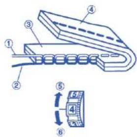
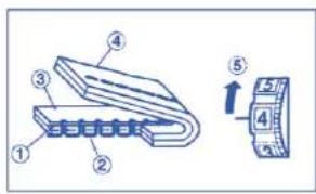
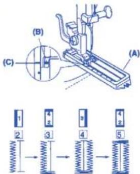
(A) (B) (C) 1 2 3 4 5Starting to sew
[1] Attach the buttonhole foot Carefully mark the buttonhole length on the fabric. Place the fabric under the foot, with the button hole marking running toward you. Move the slider (A) toward you so the top mark (C) on the slider aligns with the start mark (B). Lower the presser foot.
2 Set the stitch selector at 1.
Sew forward until you reach the front mark of your buttonhole. Stop sewing at a left stitch.
3 Set the stitch selector at 1 Sew four (4) to six (6) stitches. Stop sewing at a right stitch.
4 Set the stitch selector at Sew until you return to the start mark of the buttonhole. Stop sewing at a right stitch.
5 Set the stitch selector at Sew four (4) to six (6) stitches. Stop sewing at a left stitch.
6 Remove the fabric and place a pin just before the bartack at each end to prevent cutting bartacks. Cut the opening with the buttonhole opener.
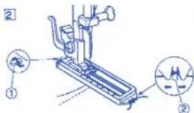
NOTE:
When sewing a buttonhole at the edge of a fabric, set the sliding buttonhole foot as illustrated and sew in reverse

1 2
text_image
Technical diagram of a sewing machine with labeled parts and two views of the base3

▶ Corded buttonhole
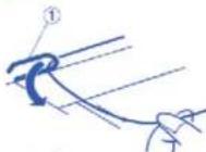
1 With the buttonhole foot raised, hook the filler cord on the spur at the back of the buttonhole foot. Bring the ends toward you under the buttonhole foot, clearing the front end. Hook the filler cord into the forks on the front of the buttonhole foot to hold them tight.
① Spur
② Forks
② Sew the buttonhole over the cord in the same procedure as above, Remove the fabric from the machine and cut the sewing threads only.
3 Pull the left end of the filler cord to lighten it. Thread the end through a darning needle, draw to the wrong side of the fabric and cut.
▶ SECTION 6. CARE OF YOUR MACHINE
1

2

1

2

3

text_image
Technical diagram of a mechanical assembly with numbered components and directional arrows indicating motion or assembly.WARNING: Switch off and unplug the machine before carrying out any maintenance or adjustment.
NOTE:
Turn off the power switch and/or unplug the machine before cleaning the machine. Do not dismantle the machine other than as explained in this section.
▶ Cleaning the Feed Dog
Remove the needle and the presser foot. Remove the needle plate set screw and remove the needle plate.
② With a brush, clean out dust and lint clogging the feed dog teeth. Reset the needle plate.
- Cleaning the hook race area To dismantle hook race unit:
① Raise the needle to its highest position and open the hook cover.
② Open the hinged latch of bobbin case and take it out of the machine.
Open the hook race ring holders and remove the hook race ring.
Remove the hook.
Clean the hook race with a brush and a soft dry cloth.
① Bobbin case
2 Hook race ring holders
③ Hook race ring
② Hook
⑤ Hook race
To assemble hook race unit:
3 Hold the hook by the center pin and fit it carefully back into the hook race^ forming a perfect circle with the shuttle driver.
Attach the hook race ring making sure the bottom pin fits into the notch.
Lock the hook race ring by turning the holders back into position, Insert the bobbin case.
⑤ Pin
⑦ Notch
▶ ENGLISH

natural_image
Technical line drawing of a mechanical component with a dashed line indicating a dimension (no text or symbols present)
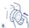
▶ Replacing the Light Bulb
CAUTION:
As the light bulb could be HOT. Protect your fingers when you handle it.
Unplug the machine.
Remove the setscrew and face cover.
- Turn the bulb counterclockwise to remove.
- Replace with a new bulb and turn it clockwise.
WARNING: Switch off and unplug the machine before carrying out any maintenance or adjustment
NOTE:
Do not store the machine in a high-humidity area, near a heat radiator or in direct sunlight.
Clean the outside of the machine with a soft cloth and mild soap.
Troubleshooting
Condition Cause Reference
| The needle 1. The needle thread is not threaded properly Page 17thread breaks 2. The needle thread tension is too light Page 183. The needle is incorrectly inserted Page 154. The needle is incorrectly inserted. Page 155. The needle thread and the bobbin thread Page 19are not set properly under the presser footat the beginning of sewing6. The threads are not drawn to the rear Page 19after finishing sewing7. The thread is too heavy, or too fine for the needle. Page 15 | |
| The bobbinthread breaks properly in the bobbin case and shuttle2. Lint has collected in the shuttle area Page 163. The bobbin is damaged and doesn'tturn smoothly Change the bobbin | |
| The needle breaks | 1. The needle is incorrectly inserted Page 152. The needle is bent or blunt Page 153. The needle clamp screw is loose Page 154. The needle thread tension is too tight Page 185. The threads are not drawn to the rear Page 19after the finishing sewing6. The needle is too fine for the fabric Page 15being sewn being sewn |
| Skipped stitches | 1. The needle is incorrectly inserted Page 152. The needle is bent or blunt Page 153. The needle and/or threads are not suitablePage 15for the work being sewn4. The needle thread is not threaded properly Page 175. The wrong needle is being used Change the needle |
| Seam puckering | 1. The needle thread tension is too light Page 182. The needle thread is not threaded properly Page 173. The needle is too heavy for the fabric Page 15being sewn |
ENGLISH
Condition Cause Reference
The fabric is not fed 1. The feed dog is packed with lint Page 18
The machine 1. The machine is not plugged in Page 14 does not run 2. A thread is caught in the shuttle race Page 22 3. The push-clutch is disengaged Page 15
The machine is 1. There is thread caught in the hook race Page 22 noisy 2. Lint has built up in the shuttle or the Page 22 shuttle race
INVENTA 100
Type 80300
220-240 V \~ 50 Hz - 85 W
Made in P.R.C

Termozeta S.p.A. reserves the right to introduce technical and/or aesthetic changes to its products intended to improve performance. Termozeta is an international trademark. Copyright © 1905. All rights reserved.
Improve performances. Termozeta is an international trademark. Copyright © 1995. All rights reserved. Termozeta S.p.A. - Via Magenta, 41/43 - 20010 Bareggio (MI) Italy
→ UNITED KINGDOM
INFORMATION FOR USERS
In accordance with European Directives 2002/95/CE, 2002/96/CE and 2003/108/CE on the restriction of
the use of dangerous substances in electric and electronic equipment as well as their waste disposal.
- The barred symbol of the rubbish bin shown on the equipment indicates that, at the end of its useful life, the product must be collected separately from other waste.
• Therefore, any products that have reached the end of their useful life must be given to waste disposal centres specialising in separate collection of waste electrical and electronic equipment, or given back to the retailer at the time of purchasing new similar equipment, on a one for one basis.
• The adequate separate collection for the subsequent start-up of the equipment sent to be recycled, treated and disposal of in an environmentally compatible way contributes to preventing possible negative effects on the environment and health and optimises the recycling and reuse of components making up the apparatus.
- Abusive disposal of the product by the user involves application of the administrative sanctions according to the laws in force.

▶ FRANÇAIS
▶ PRESCRIPTION POUR LA SÉCURITÉ

text_image
Diagram showing five labeled parts of a mechanical or electrical component, including rollers, tools, and a pen-like device.text_image
Diagram of a device connection setup with labeled components including power source, cable, and terminal block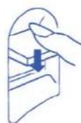

text_image
Technical diagram showing a mechanical assembly with numbered components and directional arrows indicating motion or force.text_image
Technical diagram showing a mechanical assembly with numbered components, likely illustrating a turning or cutting process.Tablette extensible
text_image
Diagram of a medical or laboratory procedure with labeled parts including a tool, pen, and tubing
natural_image
Pure technical line drawing of a mechanical component without any text, numbers, or symbols▶ Changez l'aiquille
text_image
Diagram showing a sewing machine needle stitching fabric, with labeled component '①' indicating the mechanism.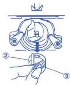
text_image
Technical diagram showing a mechanical assembly with labeled parts, including a crown and three numbered components.
text_image
Diagram showing a hand holding a small mechanical component with numbered parts labeled ③ and ④.text_image
Technical diagram of a mechanical assembly with numbered components and exploded views5

6


text_image
Technical diagram of a mechanical device with numbered components and directional arrows indicating movement or assembly.1

2

3
natural_image
Technical line drawing of a sewing machine with no visible text or symbolstext_image
Technical diagram of a sewing machine with labeled parts and a hand pointing to the base partnatural_image
Line drawing of a sewing machine needle and base (no text or symbols)text_image
Technical diagram of a mechanical assembly with numbered components and a magnified view showing a scale.text_image
Diagram showing a mechanical assembly with numbered components and an arrow indicating direction, alongside a separate labeled component.text_image
Technical diagram showing a mechanical component with numbered parts and a magnified view of a cylindrical component with labeled parts.natural_image
Line drawing of a sewing machine needle and chain (no text or symbols)text_image
Technical diagram showing three-step sewing process with labeled steps and corresponding fabric piecesPARTIE 4. POINTS DÉCORATIFS
text_image
Diagram showing three-step mechanical assembly steps with labeled parts and directional arrowstext_image
Technical diagram of a mechanical device with labeled parts (A) and (B), showing spring assembly steps.text_image
Technical diagram of a sewing machine with labeled parts and two views of the base3
Boutonnière gansées
text_image
Technical diagram of a mechanical assembly with numbered components and directional arrows indicating motion or flow.ATTENTION:
natural_image
Technical line drawing of a mechanical component with a dashed line indicating a dimension (no text or symbols present)
text_image
Diagram of a device connection setup with labeled parts including power supply, cable, and terminal block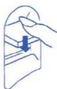
text_image
Technical diagram of a sewing machine with numbered parts and directional arrows indicating motion or assembly.text_image
Diagram of a medical or laboratory procedure with labeled parts including a tool, device, and probe.
natural_image
Pure technical line drawing of a mechanical component without any text, numbers, or symbolstext_image
Diagram showing a sewing machine needle stitching fabric, with labeled component '①' indicating the mechanism.text_image
Technical diagram showing a mechanical assembly with labeled parts, including a crown and three numbered components.text_image
Diagram showing a hand holding a small mechanical component with numbered parts labeled ③ and ④.text_image
Technical diagram of a mechanical device with numbered components and exploded views, likely illustrating a turning or assembly process.text_image
Technical diagram of a mechanical device with numbered components and directional arrows indicating movement or assembly.1
2

4 5

natural_image
Technical line drawing of a sewing machine with no visible text or symbolstext_image
Technical diagram of a sewing machine with labeled parts and hand gesturenatural_image
Line drawing of a sewing machine needle and screwdriver (no text or symbols)text_image
Technical diagram of a mechanical assembly with numbered components and a magnified view showing internal structure.text_image
Diagram illustrating a mechanical or electrical component with numbered parts and an arrow indicating direction, alongside a circular scale.text_image
Technical diagram showing labeled components of a mechanical or electronic component with numbered parts and a directional arrow indicating movement.Demaslada tensión
natural_image
Line drawing of a sewing machine needle and chain (no text or symbols)text_image
Technical diagram showing three-step sewing process with labeled steps and corresponding fabric piecestext_image
Diagram showing four different mechanical or electrical component configurations with numbered labels.text_image
Technical diagram of a mechanical device with labeled parts (A) and (B), showing spring assembly steps.text_image
Technical diagram of a sewing machine with labeled parts and two views of the base3
Ojales acordonados
text_image
Technical diagram of a mechanical assembly with numbered components and directional arrows indicating motion or flow.natural_image
Technical line drawing of a mechanical component with a dashed line indicating a dimension (no text or symbols present)