
DH 25PA - Drill HITACHI - Free user manual and instructions
Find the device manual for free DH 25PA HITACHI in PDF.


| Product type | Rotary hammer (hammer drill) |
| Brand | Hitachi |
| Model | DH 25PA |
| Supply voltage | 110-240 V (depending on region) |
| Power consumption | 650 W |
| No-load speed | 0 – 1100 rpm |
| Impact frequency at full load | 0 – 4000 bpm |
| Drilling capacity - Concrete | 3.4 – 25 mm |
| Drilling capacity - Steel | 13 mm |
| Drilling capacity - Wood | 32 mm |
| Weight (without cord nor side handle) | 3.4 kg |
| Operating modes | Rotation + impact |
| Tool holder | SDS-plus |
| Sound power level (LWA) | 101 dB(A) |
| Sound pressure level (LpA) | 90 dB(A) with uncertainty K=3 dB(A) |
| Vibration (root mean square) | 9.5 m/s² |
| Supplied accessories | Plastic case, side handle, depth gauge, dust cap |
| Optional accessories | 13 mm drill chuck (for PB), tapered shank bits, core bits, screw adapter |
| Recommended lubricant | Grease A for hammer (Hitachi) |
| Brush maintenance | Check and replace carbon brushes when they reach the wear limit |
| Safety instructions | Wear hearing protection, safety glasses, avoid loose clothing, disconnect before adjustment |
| Reference standard | EN60745 |
| Destination countries | Europe (WEEE compliant) |
Frequently Asked Questions - DH 25PA HITACHI
User questions about DH 25PA HITACHI
0 question about this device. Answer the ones you know or ask your own.
Ask a new question about this device
Download the instructions for your Drill in PDF format for free! Find your manual DH 25PA - HITACHI and take your electronic device back in hand. On this page are published all the documents necessary for the use of your device. DH 25PA by HITACHI.
USER MANUAL DH 25PA HITACHI
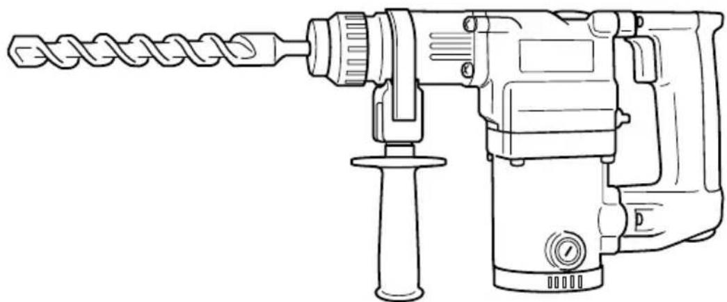
Rotary Hammer Bohrhammer Perforateur percussion Martello perforatore Boorhamer Martillo perforador Martelo perfurador Σφυροδραπανο περιζτροφικο
DH 25PA · DH 25PB
natural_image
Line drawing of a drill bit with a coiled drill, no text or symbols presentRead through carefully and understand these instructions before use. Diese Anleitung vor Benutzung des Werkzeugs sorgfältig durchlesen und verstehen. Lire soigneusement et bien assimiler ces instructions avant usage. Prima dell'uso leggere attentamente e comprendere queste istruzioni. Deze gebruiksaanwijzing s.v.p. voor gebruik zorgvuldig doorlezen. Leer cuidadosamente y comprender estas instrucciones antes del uso. Antes de usar, leia com cuidado para assimilar estas instruções. Διαβάστε προσεκτικά και κατανοήσετε αυτές τις οδηγίες πριν τη χρήση.

Handling instructions Bedienungsanleitung Mode d'emploi Istruzioni per l'uso Gebruiksaanwijzing Instrucciones de manejo Instruções de uso Οδηγίες χειρισμού
1
2
3

4
natural_image
Technical line drawing of a mechanical component with mounting holes and a bracket (no text or symbols)5

6

natural_image
Line drawing of a hand using a drill bit with a dot pattern on the right side (no text or symbols)7
8





natural_image
Line drawing of a hand operating a drill bit with a tool, no text or symbols present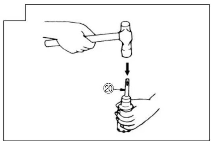
18

| a26 | ||
| 27 | 5mm 21 | |
| 28- | 7 | 0 |
| English Deutsch | Français Italiano | |||
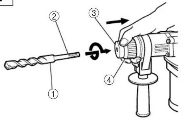
| 1Drill bit Bohrer Foret de pergage | Punta del trapano | |||
| 2Part of SDS-plus shank | Teii des SDS-plus Elément de la tige SDS Schaftes plus | Parte dell'asta SDS plus | ||
| 3Front cap Vordere Abdeckung | Capuchon avant | Protezione davanti | ||
| 4Grip Spannbacke | Attache coulissante | Presa davanti | ||
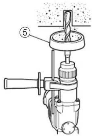
| 5 | Dust cup | Staubschale | Godet à poussière | Contenitore a polvere |
| 6Dust collector (B) | Staubfänger (B) | Collecteur à poussière (B) | Camera a polvere (B) | |
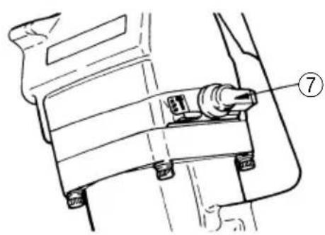
| 7Change lever | Wahlhebel | Sélecteur | Leva di selezione | |
| 8 | Drill chuck | Bohrfutter | Mandrin porte-foret | Mandrino |
| 9Chuck adapter (DH25PB) | Bohrfutteradapter (DH25P) | Raccord de mandrin (DH25PB) | Adattatore per mandrino (DH25PB) | |
| 10Bit | Bohrerspitze | Mèche | Punta | |
| 11Socket | Fassung | Prise | Presa | |
| 12 | Chuck adapter (D) (DH25PB) | Bohrfutteradapter (D) (DH25PB) | Raccord (D) de mandrin (DH25PB) | Adattatore (D) per mandrino (DH25PB) |
| 13 | Side handle | Handgriff | Poignée laterale | Laterale |
| 14Stopper | Anschlag | Quenouille | Fermo | |
| 15 | Mounting hole | Befestigungsöffnung | Orifice de montage | Foro d'inserimento della bacchetta di arresto |
| 16Tape shank adapter Kegelschaftadapter | Raccord de queue conique | Adattatore per gambo conico | ||
| 17Cotter | Dorn | Clavette | Coppiglia | |
| 18Rests | Auflage | Support | Appoggio | |
| 19Core bit | Bohrkrone | Couronne | Corona | |
| 20Core bit shank | Bohrkronenzapfen Queue de couronne | Gambo della corona | ||
| 21Thread | Gewinde | Filetage | Filettatura | |
| 22 | Center pin | Mittelstift | Goujon central | Punta della corona |
| 23 | Guide plate | Führungsplatte | Plaque de guidage | Piastra guida |
| 24 | Core bit tip | Bohrkronenspitze | Bout de couronne | Punta della corona |
| 25 | Wear limit | Verschleißgrenze | Limite d'usure | Limite di usura |
| 26 | No. of carbon brush | Nr. der Kohlebürste | No. de balai en carbone | N. della spazzola di carbone |
| 27Usual carbon brush | Gewöhnliche Kohlebürste | Balai en carbone ordinaire | Spazzola di carbonecomune | |
| 28Auto-stop carbon brush | Auto-Stop Kohlebürste | Balai en carbone à arrêt automatique | Spazzolz di carbone ad arresto automatico | |
| Nederlands Español | Português Ελληνικά | |||
| 1Boorstuk Broca | Broca | Λεπίδα τρυπανιού | ||
| 2 | Onderdeel van SDS Plus schacht vástago | Parte del SDS más | Cabo de peça SDS-plus | Τμήμα του SDS-plus στελέχους |
| 3Voorkap Cubierta frontal | Tampa da frente | Μπροστινό περίβλημα | ||
| 4Greep Sujetador | Mordente | Λαβή | ||
| 5Stofvangkap Capa de polvo | Receptáculo para poeira | Κύπελλο σκόνης | ||
| 6Stofverzamelaar (B) Colector | de polvo (B) | Coletor de poeira (B) | Συλλέκτης σκόνης (B) | |
| 7Keuzeschakelaar Palanquita selectora | Seletor | Μοχλός αλλαγής | ||
| 8Boorkop Portabrocas | Mandril | Σφικτήρας τρυπανιού | ||
| 9 | Boorkopadaptor Adaptador del (DH25PB) portabrocas (DH25PB) | Adaptador do mandril (DH25PB) | Προσαρμογέας σφικτήρα (DH25PB) | |
| 10Boorstuk Broca | Palhetão | Λεπίδα | ||
| 11Aansluithuls Cubo | Encaixe | Υποδοχή | ||
| 12 | Boorkopadaptor (D) Adaptador (D) del (DH25PB) portabrocas (DH25PB) | Adaptador do mandril (D) (DH25PB) | Προσαρμογέας σφικτήρα (D) (DH25PB) | |
| 13Zijgreep Mango lateral | Empunhadura lateral | Πλευρική λαβή | ||
| 14Stopper | Tope | Tampão | Στόπερ | |
| 15Montagegat | Agujero de montaje | Orifício de montagem | Τρύπα στερέωσης | |
| 16 | Vernauwde schachtadaptor | Adaptador de la espiga ahusada | Adaptador de cabo cônico | Κωνικός προσαρμογέας στελέχους |
| 17Cotter Chaveta | Cavilha | Κόφτης | ||
| 18Steun | Apoyo | Suporte | Στήριγμα | |
| 19Kernstuk | Barrena tubular | Coroa | Κυλινδρικό κοπτικό τμήμα | |
| 20Kernstukschacht | Espiga de la barrena tubular | Cabo de coroa | Άξονας κυλινδρικού κοπτικού τμήματος | |
| 21Schroefdraad | Rosca | Rosca | Σπείρωμα | |
| 22Middenpin | Pasador central | Pino central | Κεντρική περόνη | |
| 23Pasplaatje | Placa guía | Placa-guía | Οδηγητική πλάκα | |
| 24Top van kernstuk | Punta de barrena tubular | Cabo da coroa | Άκρη κυλινδρικού κοπτικού τμήματος | |
| 25Slijtagegrens | Límite de desgaste | Limite de desgaste | Όριο φθοράς | |
| 26Nr. van koolborstel | No. de escobilla de carbón | No da escova de carvão | Αρ. καρβουνακίων | |
| 27Normale koolborstel | Escobilla de carbón usual | Escova de carvão normal | Συνηθισμένο καρβουνάκι | |
| 28Auto-stop koolborstel | Escobilla de carbón de parada automática | Escova de carvão de parada automática | Καρβουνάκι αυτόματης διακοπής | |
GENERAL SAFETY RULES
WARNING!
Read all instructions
Failure to follow all instructions listed below may result in electric shock, fire and/or serious injury.
The term "power tool" in all of the warnings listed below refers to your mains operated (corded) power tool or battery operated (cordless) power tool.
SAVE THESE INSTRUCTIONS
1) Work area
a) Keep work area clean and well lit.
Cluttered and dark areas invite accidents.
b) Do not operate power tools in explosive atmospheres, such as in the presence of flammable liquids, gases or dust.
Power tools create sparks which may ignite the dust of fumes.
c) Keep children and bystanders away while operating a power tool.
Distractions can cause you to lose control.
2) Electrical safety
a) Power tool plugs must match the outlet.
Never modify the plug in any way.
Do not use any adapter plugs with earthed (grounded) power tools.
Unmodified plugs and matching outlets will reduce risk of electric shock.
b) Avoid body contact with earthed or grounded surfaces such as pipes, radiators, ranges and refrigerators. There is an increased risk of electric shock if your body is earthed or grounded.
c) Do not expose power tools to rain or wet conditions. Water entering a power tool will increase the risk of electric shock.
d) Do not abuse the cord. Never use the cord for carrying, pulling or unplugging the power tool. Keep cord away from heat, oil, sharp edges or moving parts. Damaged or entangled cords increase the risk of electric shock.
e) When operating a power tool outdoors, use an extension cord suitable for outdoor use.
Use of a cord suitable for outdoor use reduces the risk of electric shock
3) Personal safety
a) Stay alert, watch what you are doing and use common sense when operating a power tool.
Do not use a power tool while you are tired or under the influence of drugs, alcohol or medication. A moment of inattention while operating power tools may result in serious personal injury.
b) Use safety equipment. Always wear eye protection. Safety equipment such as dust mask, non-skid safety shoes, hard hat, or hearing protection used for appropriate conditions will reduce personal injuries.
c) Avoid accidental starting. Ensure the switch is in the off position before plugging in. Carrying power tools with your finger on the switch or plugging in power tools that have the switch on invites accidents.
d) Remove any adjusting key or wrench before turning the power tool on.
A wrench or a key left attached to a rotating part of the power tool may result in personal injury.
e) Do not overreach. Keep proper footing and balance at all times.
This enables better control of the power tool in unexpected situations.
f) Dress properly. Do not wear loose clothing or jewellery. Keep your hair, clothing and gloves away from moving parts.
Loose clothes, jewellery or long hair can be caught in moving parts.
g) If devices are provided for the connection of dust extraction and collection facilities, ensure these are connected and properly used.
Use of these devices can reduce dust related hazards.
4) Power tool use and care
a) Do not force the power tool. Use the correct power tool for your application.
The correct power tool will do the job better and safer at the rate for which it was designed.
b) Do not use the power tool if the switch does not turn it on and off.
Any power tool that cannot be controlled with the switch is dangerous and must be repaired.
c) Disconnect the plug from the power source before making any adjustments, changing accessories, or storing power tools.
Such preventive safety measures reduce the risk of starting the power tool accidentally.
d) Store idle power tools out of the reach of children and do not allow persons unfamiliar with the power tool or these instructions to operate the power tool.
Power tools are dangerous in the hands of untrained users.
e) Maintain power tools. Check for misalignment or binding of moving parts, breakage of parts and any other condition that may affect the power tools operation.
If damaged, have the power tool repaired before use.
Many accidents are caused by poorly maintained power tools.
f) Keep cutting tools sharp and clean.
Properly maintained cutting tools with sharp cutting edges are less likely to bind and are easier to control.
g) Use the power tool, accessories and tool bits etc., in accordance with these instructions and in the manner intended for the particular type of power tool, taking into account the working conditions and the work to be performed.
Use of the power tool for operations different from intended could result in a hazardous situation.
5) Service
a) Have your power tool serviced by a qualified repair person using only identical replacement parts.
This will ensure that the safety of the power tool is maintained.
PRECAUTION
Keep children and infirm persons away. When not in use, tools should be stored out of reach of children and infirm persons.
PRECAUTIONS ON USING ROTARY HAMMER
- Wear earplugs to protect your ears during operation.
-
Do not touch the bit during or immediately after operation. The bit becomes very hot during operation and could cause serious burns.
-
Before starting to break, chip or drill into a wall, floor or ceiling, thoroughly confirm that such items as electric cables or conduits are not buried inside.
- Always hold the body handle and side handle of the power tool firmly. Otherwise the counterforce produced may result in inaccurate and even dangerous operation.
SPECIFICATIONS
| Model DH25PA DH25PB | ||
| Voltage (by areas)* (110V, 115V, 120V, 127V, 220V, 230V, 240V) | ||
| Power Input 650W* | ||
| No-load speed 0 – 1100/min. | ||
| Full-load impact rate 0 – 4000/min. | ||
| Capacity: concretesteelwood | 3.4 – 25 mm13 mm32 mm | |
| Weight (without cord and side handle) | 3.4 kg | |
| Function | Rotation + Striking | Rotation + Striking, Rotation only |
*Be sure to check the nameplate on product as it is subject to change by areas.
STANDARD ACCESSORIES
(1) Case (Molded plastic) 1
(2) Side handle 1
(3) Stopper 1
(4) Dust cup 1
Standard accessories are subject to change without notice.
OPTIONAL ACCESSORIES (sold separately)
- Drilling anchor holes (Rotation + Striking)
○ Drill bit (Slender shaft)

| Drill bit (slender shaft) | ||
| Outer diameter | Effective length | Overall length |
| 3.4 mm | 45 mm | 90 mm |
| 3.5 mm | ||

natural_image
Line drawing of a mechanical drill press with no visible text or symbols○Drill bit (Taper shank) and taper shank adapter

Drill bit (Taper shank)

Taper shank adapter (SDS-plus shank)

natural_image
Line drawing of a mechanical drill bit with no text or symbols
Cotter
| Outer diameter |
| 11.0 mm |
| 12.3 mm |
| 12.7 mm |
| 14.3 mm |
| 14.5 mm |
| 17.5 mm |
| 21.5 mm |
| Taper mode Applicable | drill bit | |
| Morse taper (No.1) Drill | bit (taper shank) 11.0 – 17.5 mm | |
| Morse taper (No.2) Drill | bit (taper shank) 21.5 mm | |
| A-taper Taper shank adapter formed A-taper or B-taper is provided as an optional accessory, but the drill bits for them are not provided. | ||
| B-taper | ||
○13 mm Hammer drill chuck (DH25PB only)
For drilling operations when using a straight shank bit for impact drilling with a hammer drill.

- Anchor setting (Rotation + Striking)
○Anchor setting adapter (for a rotary hammer)

| Anchor size |
| W1/4" |
| W5/16" |
| W3/8" |
| W1/2" |

natural_image
Line drawing of a drill bit with handle and screw base (no text or symbols)○Anchor setting adapter (for a manual hammer)
| Anchor size |
| W1/4" |
| W5/16" |
| W3/8" |
| W1/2" |
| W5/8" |

Anchor setting adapter (for a manual Hammer)


3. Large hole boring (Rotation + Striking)
○Center pin, core bit, core bit shank and guide plate.

| Center pin Core bit (outer diameter) Core bit shank | |||
| -25 mm | (A) 32 mm | 29 mm | |
| Center pin (A) 35 mm | Core bit shank (A)38 mm | ||
| Center pin (B) (B) 65 mm Core | bit shank (B) | 45 mm50 mm80 mm90 mm | |
| Do not use core bits with with outer diameter of 25 mm (The guide plate is not equipped with core bits and 29 mm. with outer diameters of 25 mm and 29 mm.) | |||
4. Bolt placing operation with Chemical Anchor. (Rotation + Striking)

5. Drilling holes (Rotation only) (DH25PB only)
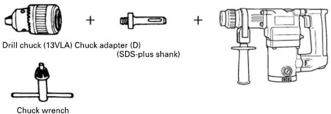
○ 13 mm drill chuck ass'y (includes chuck wrench) and chuck (for drilling in steel or wood).
6. Driving Screws (rotation only) (DH25PB only)


natural_image
Line drawing of a drill bit with no text or symbols| Bit No. Screw Size Length | |
| No. 2 3 – 5 mm 25 mm | |
| No. 3 6 – 8 mm 25 mm |
7. Dust cup and Dust collector (B)
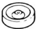
Dust cup

Dust collector (B)
Optional accessories are subject to change without notice.
APPLICATIONS
Rotation and striking function
○Drilling anchor holes
○Drilling holes in concrete
○Drilling holes in tile
Rotation only function
○Drilling in steel or wood (with optional accessories)
○Tightening machine screws, wood screws (with optional accessories)
PRIOR TO OPERATION
1. Power source
Ensure that the power source to be utilized conforms to the power requirements specified on the product nameplate.
2. Power switch
Ensure that the power switch is in the OFF position. If the plug is connected to a receptacle while the power switch is in the ON position, the power tool will start operating immediately, which could cause a serious accident.
3. Extension cord
When the work area is removed from the power source, use an extension cord of sufficient thickness and rated capacity. The extension cord should be kept as short as practicable.
4. Mounting the drill bit (Fig. 1)
(1) To attach a drill bit (SDS-plus shank), fully pull the grip in the direction of the arrow as shown in Fig. 1 and insert the drill bit as far as it will go while manually turning.
(2) By releasing the grip, the drill bit will be secured.
(3) To remove the drill bit, fully pull the grip in the direction of the arrow and pull out the drill bit.
8. Hammer grease A
500 g (in a can)
70 g (in a green tube)
30 g (in a green tube)
- Installation of dust cup (standard accessory) or dust collector (B) (Optional accessory) (Fig. 2, Fig. 3)
When using a rotary hammer for upward drilling operations attach a dust cup or dust collector (B) to collect dust or particles for easy operation.
○Installing the dust cup
Use the dust cup by attaching to the drill bit as shown in Fig. 2.
When using a bit which has big diameter, enlarge the center hole of the dust cup with this rotary hammer.
○Installing dust collector (B)
When using dust collector (B), insert dust collector (B) from the tip of the bit by aligning it to the groove on the grip. (Fig. 3)
CAUTION:
The dust cup and dust collector (B) are for exclusive use of concrete drilling work. Do not use them for wood or metal drilling work.
○Insert dust collector (B) completely into the chuck part of the main unit.
When turning the rotary hammer on while dust collector (B) is detached from a concrete surface, dust collector (B) will rotate together with the drill bit. Make sure to turn on the switch after pressing the dust cup on the concrete surface. (When using dust collector (B) attached to a drill bit that has more than 190 mm of overall length, dust collector (B) cannot touch the concrete surface but rotates. Therefore please use dust collector (B) by attaching to drill bits which have 166 mm, 160 mm, and 110 mm overall length.
○Dump particles after every two or three holes drilling.
○Please replace the drill bit after removing dust collector (B).
6. Selecting a driver bit
Screw heads or bits will be damaged should an inappropriate bit for the screw diameter be employed to drive in the screws.
HOW TO USE
CAUTION:
To prevent accidents, make sure to turn the switch off and disconnect the plug from the receptacle when the drill bits and other various parts are installed or removed. The power switch should also be turned off during a work break and after work.
1. Switch operation
The rotation speed of the drill bit can be controlled steplessly by varying the amount that the trigger switch is pulled. Speed is low when the trigger switch is pulled slightly and increases as the switch is pulled more.
This rotary hammer can be set to rotation and striking mode by rotating the change lever (DH25PB only) fully counter-clockwise to mark. (Fig. 5)
(1) Mount the drill bit.
(2) Pull the trigger switch after applying the drill bit tip to the drilling position. (Fig. 6)
(3) Pushing the rotary hammer forcibly is not necessary at all. Pushing slightly so that drill dust comes out gradually is sufficient.
CAUTION:
When the drill bit touches a rebar, the bit will stop immediately and the rotary hammer will react to revolve. Therefore grip the side handle and handle tightly as shown in Fig. 6.
3. Rotation only (DH25PB)
The rotary hammer can be set to rotation only mode by rotating the change lever fully clockwise to mark. (Fig. 7)
To drill wood or metal material using the drill chuck and chuck adapter (optional accessory), carry out as follows.
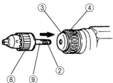
Installing drill chuck and chuck adapter: (Fig. 8)
(1) Mount the drill chuck to the chuck adapter.
(2) The part of the SDS-plus shank is the same as the drill bit. Therefore, refer to the item of "Mounting the drill bit" for attaching it.
CAUTIONS:
○Application of force more than necessary will not only decelerate the working efficiency, but it will deteriorate the tip edge of the drill bit and reduce the service life of the rotary hammer as well.
○Do not attempt to drill anchor holes or holes in concrete with the machine set in the rotation only function.
☐Do not attempt to use the rotary hammer in the rotation and striking function with the drill chuck and chuck adapter attached. This would seriously shorten the service life of each component of the power tool.
4. When driving machine screws (Fig. 9)
First, insert the bit into the socket in the end of chuck adapter (D).
Next, mount chuck adapter (D) on the main unit using procedures described in 4 (1), (2), (3), put the tip of the bit in the slots in the head of the screw, grasp the main unit and tighten the screw.
CAUTIONS:
Exercise care not to excessively prolong driving time, otherwise, the screws may be damaged by excessive force.
○Apply the rotary hammer perpendicularly to the screw head when driving the screw; otherwise, the screw head or bit will be damaged, or driving force will not be fully transferred to the screw.
○Do not attempt to use the rotary hammer in the rotation and striking function with the chuck adapter and bit attached.
5. When driving wood screws (Fig. 9)
(1) Selecting a suitable driver bit Recommended to employ cross-recessed screws, since the driver bit easily slips off the heads of slotted-head screws.
(2) Driving in wood screws
○Prior to driving in wood screws, make pilot holes suitable for them in the wooden board. Apply the bit to the screw head recesses and gently drive the screws into the holes.
○After rotating the rotary hammer at low speed for a while until the wood screw is partly driven into the wood, squeeze the trigger more strongly to obtain the optimum driving force.
CAUTION:
Exercise care in preparing a pilot hole suitable for the wood screw taking the hardness of the wood into consideration. Should the hole be excessively small or shallow, requiring much power to drive the screw into it, the thread of the wood screw may sometimes be damaged.
6. Using the stopper (Fig.10)
(1) Loosen the knob on the side handle, and insert the stopper into the mounting hole on the side handle.
(2) Adjust the stopper position according to the depth of the hole and tighten the knob securely.
7. How to use the drill bit (taper shank) and the taper shank adapter
(1) Mount the taper shank adapter to the rotary hammer. (Fig. 11)
(2) Mount the drill bit (taper shank) to the taper shank adapter. (Fig. 11)
(3) Turn the switch ON, and drill a hole in prescribed depth.
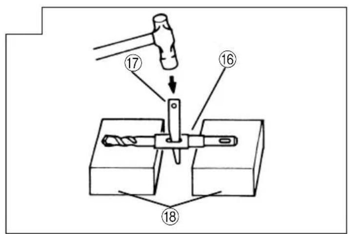
(4) To remove the drill bit (taper shank), insert the cotter into the slot of the taper shank adapter and strike the head of the cotter with a manual hammer supporting on the rests. (Fig. 12)
HOW TO USE THE CORE BIT (FOR LIGHT LOAD)
When boring penetrating large holes use the core bit (for light loads). At that time use with the center pin and the core bit shank provided as optional accessories.
1. Mounting CAUTION
Be sure to turn power OFF and disconnect the plug from the receptacle.
(1) Mount the core bit to the core bit shank. (Fig. 13). Lubricate the thread of the core bit shank to facilitate disassembly.
(2) Mount the core bit to the rotary hammer (Fig. 14).
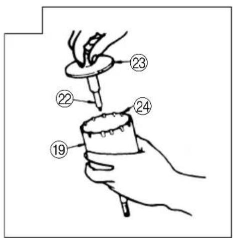
(3) Insert the center pin into the guide plate until it stops.
(4) Engage the guide plate with the core bit, and turn the guide plate to the left or the right so that it does not fall even if it faced downward. (Fig. 15).
2. How to bore (Fig. 16)
(1) Connect the plug to the power source.
(2) A spring is installed in the center pin.
Push it lightly to the wall or the floor perpendicularly. Connect the core bit tip flush to the surface and start operating.
(3) When boring about 5 mm in depth the position of the hole will be established. Bore after that removing the center pin and the guide plate from core bit.
(4) Application of excessive force will not only decelerate the working efficiency, but it will deteriorate the tip edge of the drill bit, resulting in reduced service life of the rotary hammer.
CAUTION
When removing the center pin and the guide plate, turn OFF the switch and disconnect the plug from the receptacle.
3. Dismounting (Fig. 17)
Remove the core bit shank from the rotary hammer and strike the head of the core bit shank strongly two or three times with a manual hammer holding the core bit, then the thread becomes loose and the core bit can be removed.
LUBRICATION
Low viscosity grease is applied to this rotary hammer so that it can be used for a long period without replacing the grease. Please contact the nearest authorized service center for grease replacement when any grease is leaking from a loosened screw.
Further use of the rotary hammer with incorrect grease will cause the machine inefficiency and reduce the service life.
CAUTION:
A special grease is used with this machine, therefore, the normal performance of the machine may be badly affected by use of other grease. Please be sure to let one of our authorized service center undertaking replacement of the grease.
MAINTENANCE AND INSPECTION
1. Inspecting the drill bits
Since use of a dull tool will cause motor malfunctioning and degraded efficiency, replace the drill bit with new ones or resharpen them without delay when abrasion is noted.
2. Inspecting the mounting screws:
Regularly inspect all mounting screws and ensure that they are properly tightened. Should any of the screws be loose, retighten them immediately. Failure to do so could result in serious hazard.
3. Maintenance of the motor
The motor unit winding is the very "heart" of the power tool. Exercise due care to ensure the winding does not become damaged and/or wet with oil or water.
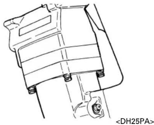
4. Inspecting the carbon brushes (Fig. 18)
The motor employs carbon brushes which are consumable parts. When they become worn to or near "wear limit", it could result in motor trouble. When an auto-stop carbon brush is equipped, the motor will stop automatically.
At that time, replace both carbon brushes with new ones which have the same carbon brush numbers shown in Fig. 18.
In addition, always keep carbon brushes clean and ensure that they slide freely within the brush holders.
5. Replacing carbon brushes:
Disassemble the brush caps with a slotted-head screwdriver. The carbon brushes can then be easily removed.
6. Service parts list
A: Item No.
B: Code No.
C: No. Used
D: Remarks
CAUTION
Repair, modification and inspection of Hitachi Power Tools must be carried out by an Hitachi Authorized Service Center.
This Parts List will be helpful if presented with the tool to the Hitachi Authorized Service Center when requesting repair or other maintenance.
In the operation and maintenance of power tools, the safety regulations and standards prescribed in each country must be observed.
MODIFICATIONS
Hitachi Power Tools are constantly being improved and modified to incorporate the latest technological advancements.
Accordingly, some parts (i.e. code numbers and/or design) may be changed without prior notice.
NOTE:
Due to HITACHI's continuing program of research and development, the specifications herein are subject to change without prior notice.
IMPORTANT
Correct connection of the plug
The wires of the mains lead are coloured in accordance with the following code:
Blue: -Neutral
Brown: -Live
As the colours of the wires in the mains lead of this tool may not correspond with the coloured markings identifying the terminals in your plug proceed as follows: The wire coloured blue must be connected to the terminal marked with the letter N or coloured black. The wire coloured brown must be connected to the terminal marked with the letter L or coloured red. Neither core must be connected to the earth terminal.
NOTE:
This requirement is provided according to BRITISH STANDARD 2769: 1984.
Therefore, the letter code and colour code may not be applicable to other markets except The United Kingdom.
Information concerning airborne noise and vibration The measured values were determined according to EN60745 and declared in accordance with ISO 4871.
Measured A-weighted sound power level: 101 dB (A) Measured A-weighted sound pressure level: 90 dB (A) Uncertainty KpA: 3 dB (A).
Wear ear protection.
The typical weighted root mean square acceleration value: 9.5 m/s2 .
natural_image
Line drawing of a mechanical drill bit with no text or symbolsnatural_image
Line drawing of a mechanical drill bit with no text or symbols
Dorn
| Ankergröße |
| W1/4" |
| W5/16" |
| W3/8" |
| W1/2" |

natural_image
Line drawing of a mechanical drill bit with no text or symbols| Ankergröße |
| W1/4" |
| W5/16" |
| W3/8" |
| W1/2" |
| W5/8" |

natural_image
Line drawing of a mechanical drill press with handle and screw base (no text or symbols)natural_image
Line drawing of a mechanical drill bit with a cylindrical base and screw head (no text or symbols)natural_image
Line drawing of a drill bit with handle and screw (no text or symbols)natural_image
Line drawing of a drill bit with no text or symbols| Dimension de l'ancrage |
| W1/4" |
| W5/16" |
| W3/8" |
| W1/2" |

natural_image
Line drawing of a mechanical drill bit with no text or symbols| Dimension del'ancrage |
| W1/4" |
| W5/16" |
| W3/8" |
| W1/2" |
| W5/8" |

natural_image
Line drawing of a drill bit with handle and screw (no text or symbols)natural_image
Line drawing of a mechanical drill bit with no text or symbols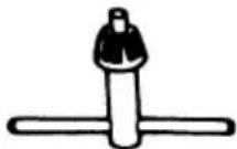
Clé de mandrin
natural_image
Line drawing of a mechanical drill bit with a cylindrical base and adjustment knob (no text or symbols)natural_image
Line drawing of a mechanical drill bit with no visible text or symbols| Anker formaat |
| W1/4" |
| W5/16" |
| W3/8" |
| W1/2" |

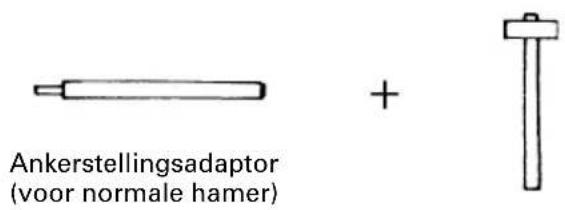
○Ankerstellingsadaptor (voor normale hamer)
| Anker formaat |
| W1/4" |
| W5/16" |
| W3/8" |
| W1/2" |
| W5/8" |
natural_image
Line drawing of a mechanical drill bit with no visible text or symbols
Sleutel
natural_image
Line drawing of a drill bit with handle and screw (no text or symbols)natural_image
Line drawing of a mechanical drill bit with no text or symbolsnatural_image
Line drawing of a drill bit with handle and screw base (no text or symbols)
Chaveta
| Diámetro externo |
| 11,0 mm |
| 12,3 mm |
| 12,7 mm |
| 14,3 mm |
| 14,5 mm |
| 17,5 mm |
| 21,5 mm |
natural_image
Line drawing of a mechanical drill bit with no visible text or symbols| Medida de ancla |
| W1/4" |
| W5/16" |
| W3/8" |
| W1/2" |

natural_image
Line drawing of a drill bit with no visible text or symbols| Medida de ancla |
| W1/4" |
| W5/16" |
| W3/8" |
| W1/2" |
| W5/8" |

natural_image
Line drawing of a mechanical drill bit with no visible text or symbolsnatural_image
Line drawing of a mechanical drill bit with no text or symbolsnatural_image
Line drawing of a drill bit with a handle and screw base (no text or symbols)
Cavilha
| Diâmetro externo |
| 11,0 mm |
| 12,3 mm |
| 12,7 mm |
| 14,3 mm |
| 14,5 mm |
| 17,5 mm |
| 21,5 mm |
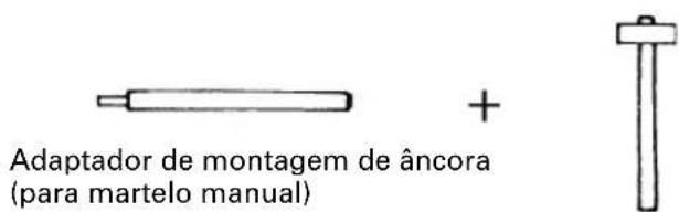
| Tamanho da âncora |
| W1/4" |
| W5/16" |
| W3/8" |
| W1/2" |
| W5/8" |
natural_image
Line drawing of a mechanical drill bit with a cylindrical base and handle (no text or symbols)(cabo SDS-plus)
natural_image
Line drawing of a drill bit with handle and screw (no text or symbols)
Chave de mandril
natural_image
Line drawing of a mechanical drill bit with no text or symbolsnatural_image
Line drawing of a mechanical drill press with no visible text or symbolsnatural_image
Line drawing of a mechanical drill bit with no text or symbolsnatural_image
Line drawing of a mechanical drill bit with a handle and screw base (no text or symbols)natural_image
Line drawing of a drill bit with no visible text or symbols(SDS-plus στέλεχος)
natural_image
Line drawing of a mechanical drill bit with no text or symbolsnatural_image
Line drawing of a quill pen with inkwell (no text or symbols)| English | Nederlands | ||
| GUARANTEE CERTIFICATE1Model No.2Serial No.3Date of Purchase4Customer Name and Address5Dealer Name and Address(Please stamp dealer name and address) | GARANTIEBEWIJS1Modelnummer2Serienummer3Datum van aankoop4Naam en adres van de gebruiker5Naam en adres van de handelaar(Stempel a.u.b. naam en adres vande de handelaar) | ||
| Deutsch | GARANTIESCHEIN1Modell-Nr.2Serien-Nr.3Kaufdaturn4Name und Anschrift des Kunden5Name und Anschrift des Händlers(Bitte mit Namen und Anschrift des Handlers abstempeln) | Español | |
| CERTIFICADO DE GARANTIA1Número de modelo2Número de serie3Fecha de adquisición4Nombre y dirección del cliente5 Nombre y dirección del distribudor(Se ruega poner el sellú del distribudor con su nombre y dirección) | |||
| Français | Português | ||
| CERTIFICAT DE GARANTIE1No. de modèle2No. de série3Date d'achat4Nom et adresse du client5Nom et adresse du revendeur(Cachet portant le nom et l'adresse du revendeur) | CERTIFICADO DE GARANTIA1Número do modelo2Número do série3Data de compra4Nome e morada do cliente5Nome e morada do distribuidor(Por favor, carímbe o nome e morada do distribuidor) | ||
| Italiano Ελληνικά | |||
| CERTIFICATO DI GARANZIA1Modello2N° di serie3Data di acquisto4Nome e indirizzo dell'acquirente5Nome e indirizzo del rivenditore(Si prega di apporre il timbro con questi dati) | ΠΙΣΤΟΠΟΙΗΤΙΚΟ ΕΓΓΥΗΣΗΣ1Αρ. Μοντέλου2Αύξων Αρ.3Ημερομηνία αγοράς4 ́Ονομα και διεύθυνση πελάτη5 ́Ονομα και διεύθυνση μεταπωλητή(Παρακαλούμε να χρησιμοποιηθεί σφραγίδα) | ||
HITACHI
| 1 | |
| 2 | |
| 3 | |
| 4 | |
| 5 |

natural_image
Symbol of a trash bin crossed with two crossed lines, representing no waste or discharge (no text or labels)English
Only for EU countries
Do not dispose of electric tools together with household waste material!
In observance of European Directive 2002/96/EC on waste electrical and electronic equipment and its implementation in accordance with national law, electric tools that have reached the end of their life must be collected separately and returned to an environmentally compatible recycling facility.
Deutsch
Nur für EU-Länder
- DH 25PA · DH 25PB
- GENERAL SAFETY RULES
- WARNING!
- Read all instructions
- SAVE THESE INSTRUCTIONS
- 1) Work area
- 2) Electrical safety
- 3) Personal safety
- 4) Power tool use and care
- 5) Service
- PRECAUTION
- PRECAUTIONS ON USING ROTARY HAMMER
- STANDARD ACCESSORIES
- OPTIONAL ACCESSORIES (sold separately)
- Large hole boring (Rotation + Striking)
- Bolt placing operation with Chemical Anchor. (Rotation + Striking)
- Drilling holes (Rotation only) (DH25PB only)
- Driving Screws (rotation only) (DH25PB only)
- Dust cup and Dust collector (B)
- APPLICATIONS
- PRIOR TO OPERATION
- Power source
- Power switch
- Extension cord
- Mounting the drill bit (Fig. 1)
- Hammer grease A
- CAUTION:
- Selecting a driver bit
- HOW TO USE
- Switch operation
- Rotation only (DH25PB)
- CAUTIONS:
- When driving machine screws (Fig. 9)
- When driving wood screws (Fig. 9)
- Using the stopper (Fig.10)
- How to use the drill bit (taper shank) and the taper shank adapter
- HOW TO USE THE CORE BIT (FOR LIGHT LOAD)
- Mounting CAUTION
- How to bore (Fig. 16)
- CAUTION
- Dismounting (Fig. 17)
- LUBRICATION
- MAINTENANCE AND INSPECTION
- Inspecting the drill bits
- Inspecting the mounting screws:
- Maintenance of the motor
- Inspecting the carbon brushes (Fig. 18)
- Replacing carbon brushes:
- Service parts list
- MODIFICATIONS
- NOTE:
- IMPORTANT
- HITACHI
- English
- Deutsch
Brand : HITACHI
Model : DH 25PA
Category : Drill