
TR 200 - Thermostat BOSCH - Free user manual and instructions
Find the device manual for free TR 200 BOSCH in PDF.


| Product type | Programmable room thermostat |
| Brand | Bosch |
| Model | TR 200 |
| Dimensions (approx.) | 90 x 130 x 30 mm |
| Weight (approx.) | 150 g |
| Power supply | 24 V DC, 0.03 A |
| Setting range | 5 to 30 °C |
| Permissible ambient temperature | 0 to +40 °C |
| Protection type | IP 20 |
| Power reserve | Approx. 2 hours |
| Thermostat output | 2.8 to 21.5 V DC (continuous) |
| Programming | Weekly, 3 day/night cycles per day |
| Operating modes | Automatic, continuous heating, economy, vacation |
| Display | Digital (time, temperature, messages) |
| Built-in sensor | Yes (disconnected if external probe RF1 connected) |
| Compatible accessories | External probe RF1, remote switch |
| Maintenance and cleaning | Soft dry cloth; no abrasive products |
| Safety | Do not connect to 230 V; do not install in damp rooms; cut power before installation |
| General information | For gas boilers with continuous regulation; compatible with Bosch Heatronic |
Frequently Asked Questions - TR 200 BOSCH
User questions about TR 200 BOSCH
0 question about this device. Answer the ones you know or ask your own.
Ask a new question about this device
Download the instructions for your Thermostat in PDF format for free! Find your manual TR 200 - BOSCH and take your electronic device back in hand. On this page are published all the documents necessary for the use of your device. TR 200 by BOSCH.
USER MANUAL TR 200 BOSCH
6 720 604 477 (00.12)
OSW
natural_image
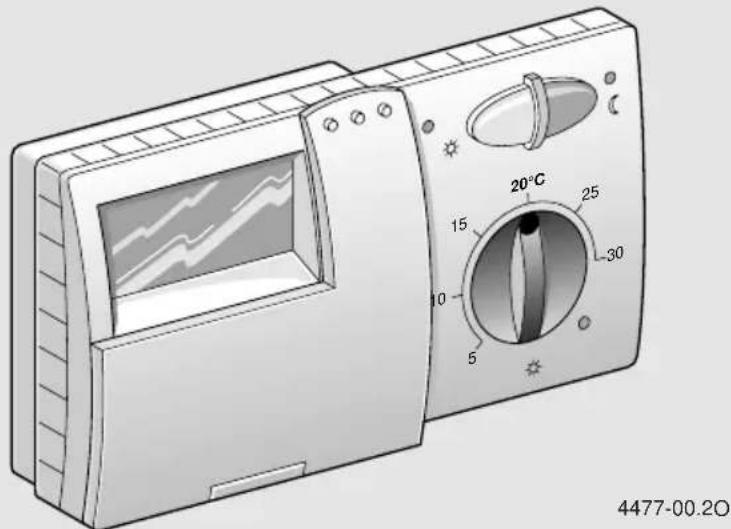
Illustration of a portable electronic device with a 20°C rotary dial and a screen showing thermal data (no text or symbols on the device itself)Deutsch
Correct function of this appliance can only be guaranteed if these instructions are observed. Please hand this document over to the customer.
Français
natural_image
Line drawing of an open book with blank pages (no text or symbols)1

2
4

3
5

Deutsch
1 Safety Instructions 16
2 Application 16
3 Technical Data 16
4 Mounting 16
5 Mains Connection 17
6 Operation 17
Setting the language 23
7 Regulator Malfunction Message 25
8 General Information 25
9 Elimination of malfunctions 26
10 Individual Heating Times 132
Français
1 Safety Instructions
The regulator is to be used only in connection with the listed gas heating units. The respective circuit diagram must be observed.
The regulator must under no circumstances be connected to the 230 V mains.
Before installing the regulator, the voltage supply (230 V, 50 Hz) to the heating unit must be interrupted.
The regulator is not suited for installation in damp rooms.
2 Application
TR 200 is a room temperature regulator with a digital time switch (weekly programme; three heating and one reduction starting times per day) for controlling the gas heating units with continuous control listed below.
| Heating unit Mains | connection | Malfunction remote indicator active |
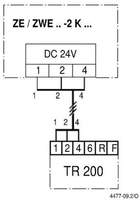
| ZE/ZWE .. - 2 K... | Illustr. 9 | no |
| ZE/ZWE .. - 2 A... | Illustr. 10 | no |
| ZR/ZWR/ZSR...-3 | Illustr. 10 | no |
| ZR/ZWR/ZSR...-4 | Illustr. 10 | no |
| Heating equipment with Bosch Heatronic Illust. yes11 | ||
TR 200 is in accordance with the regulations and is recommended for floor-areas up to approx. 80 m ^4 .
Room temperature regulators like TR 200 are not suited for buildings with underfloor heating systems. In those buildings we recommend the use of a regulator controlled by atmospheric conditions.
2.1 Scope of delivery
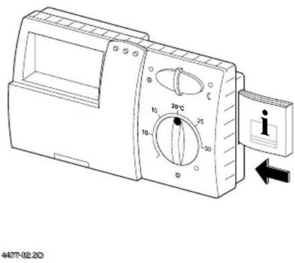
TR 200 includes the room temperature regulator with inserted brief operating instructions (illustration 2).
2.2 Accessory
An external room temperature sensor RF 1 in addition to TR 200 is available as accessory. For example, the use of this temperature sensor is of advantage when the mounting location of the regulator is not suited for measurement of temperature (see chapter 4).
Furthermore, a remote control switch (e.g. a telephone commander) can be connected by customers (see chapter 6.8).
The remote control switch must be equipped with a potential-free contact which is suited for 5 V DC.
3 Technical Data
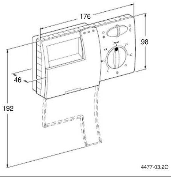
| Dimensions | see illustration 3 |
| Rated voltage 24 V DC | |
| Rated current 0.03 A | |
| Regulating range 5 to 30 °C | |
| Regulator output | constant, 2.8 to 21.5 V DC |
| Permissible ambient temperature 0 to +40 °C | |
| Operating reserve approx. 2 hrs. | |
| Protection class IP 20 | |
| CE | |
4 Mounting
Before mounting the regulator, the voltage supply (230 V, 50 Hz) to the heating unit must be interrupted.
4.1 Selecting the mounting location
It is important for the regulation quality of TR 200 to select a suitable mounting location. The installation room must be suitable for the temperature regulation of the complete heating system. The radiators installed in those rooms must not be equipped with thermostatic valves. Instead, hand valves with pre-adjustment should be installed so that the heating output of the radiators in the installation room of TR 200 can be set to the lowest possible value.
For the mounting location, select an interior wall if possible and take care that neither draughts nor heat radiation (not from behind the wall, either, e.g. through ducts or hollow walls, etc.) can have effects on the regulator.
Adequate space must be provided above and below the regulator so that the room air can circulate unimpeded through the ventilation openings (hatched area in illustration 4)
If the above mentioned conditions cannot all be met it is recommended to use the external room temperature sensor RF 1 (accessory) and to mount this on a more adequate location.
When connecting the room temperature sensor RF 1 the built-in sensor in the regulator is automatically deactivated.
4.2 Mounting the regulator
- Loosen the top (a) from the base (b) depress the fasteners on the sides (b1) oft the base and pull off the top (a) (illustration 5)
- The base (b) can be mounted either – with two screws (c) to a standard flush connection box (d) dia. 55 mm
or
- with 4 dowels (6 mm) and tallow-drop screws (dia. 3,5 mm) directly to the wall (illustration 6);
Take care that the regulator is mounted in the right position (the clip must be legible)!
- Connect with the mains accordingly (see chapter 5).
- Fit the regulator top (a).
4.3 Mounting the accessories
The accessories external room temperature sensor RF 1 and remote control switch (if existing) must be mounted according to the regulations and the respective mounting instructions.
5 Mains Connection
The following conductor cross sections from TR 200 to the heating unit must be used:
Length up to 20 m 0.75 mm ^2 up to 1.5 mm ^2 Length up to 30 m 1.0 mm ^2 up to 1.5 mm ^2 Length over 30 m 1.5 mm ^2
Considering the regulations, at least cables of the construction type H05 VV-... must be used for mains connection.
All 24 V cables (test current) must be laid separated from cables leading 230 V or 400 V so that no inductive influencing can take place (minimum distance 100 mm).
In case that inductive external influences e.g. from power current cables, contact wires, transformer towers, radio and television sets, amateur radio sets, microwave equipment, or similar are to be expected the cables leading test signals must be shielded.
The corresponding electrical connection plan (illustration 9 to 11s be followed.
5.1 Accessory mains connection
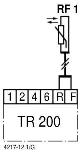
Connect the external room temperature sensor RF 1 (if existing) as shown in illustration 7.
If required, the cables of RF 1 can be extended with a cable with twisted twin conductors. This will make sure that the measured values of the sensor will not be influenced.
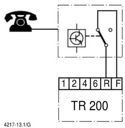
Connect the remote control switch (if existing) as shown in illustration 8 For minimum requirements see chapter 2.2 accessories.
When the switching contact of the remote control switch is deactivated the heating system will switch to economical operating mode, "F" is displayed. When the switching contact is activated the mode of operation set at the regulator is also activated (illustration 8
6 Operation
TR 200 has some operating elements which are not needed often after installation and initial operation.
Therefore all operating elements which are not needed often are covered with a lid.
The operating elements visible when the lid is closed are part of the so-called “1 ^st operating level”. All other operating elements make up the so-called “2 ^nd operating level” and the “3 ^rd operating level” res. “service level” for the expert.
All special operating states are indicated by a displayed text or by control lights. This also applies for the malfunction indicator (only for heating equipment with Bosch Heatronic).
When the lid is closed the time is shown and the measured room temperature is indicated (in 0.5 °C steps).
6.1 The "1 st operating level"
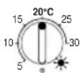
6.1.1 Control knob ⚙(k)
The room temperature to which the regulator will keep in standard heating mode is set with the control knob ⚙(k).
The regulator will always regulate the temperature to this value when the respective red control light (I) is on.
If the control knob ⚙(k) is set to “5”, the respective red control light (l) is off. The regulator will then set the temperature to approx. 5°C so that frost protection in this room is guaranteed. This means that the heating system is switched off when the temperature exceeds 6°C.
6.1.2 The operating conditions
Automatic operating mode
The basic setting of the regulator is automatic operating mode.
Automatic operating mode means automatic changeover between standard heating operation and economical operation at the times pre-set with the time switch (e).
During standard heating operation (=“day”), the regulator regulates the room temperature to the value set with the control knob (k), the respective red control light (l) is on.
During economical heating operation (=“night”), the regulator regulates the room temperature to the set economic temperature, the respective red control light (I) is off. (Pre-setting of economic temperature see chapter 6.2.1)
Note: Each time the automatic operating mode is switched off a control light comes on or a text is displayed. The operating mode can be switched back to automatic operation at any time.

Button
"Continuous heating mode" (g)
When this button is depressed ⚙(g) continuous heating operation is activated.
The regulator continuously regulates the room temperature to the value set with the control knob ⚙ (k).
The respective red control light (f) is on.
The respective red control light (l) is also on (unless the control knob (k) is set to "5").
The economical operating mode set at the time switch is ignored.
The operating mode “continuous heating” will be activated until:
- the button (g) is depressed again; the regulator will switch back to the automatic operating mode
or
- the button (h) is depressed again; the regulator will switch back to economical operating mode.
In both cases the respective red control light (f) turns off and the regulator will regulate the room temperature to the set value.
Depress this button if you exceptionally go to bed late (e.g. because of a party). Switch back to automatic operating mode later.
In case of an illness it might be more comfortable to have a higher room temperature (continuous heating operation). In this case, do not forget to switch the regulator back to the automatic operating mode.
During a winter holiday or during the summer, a low room temperature for a longer period can be selected by depressing the button "continuous heating" and additionally reducing the temperature with the control knob ⚙ (k).
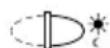
Button
"Economical operating mode" (h)
When the button (h) is depressed the economical operating mode is switched on.
The regulator continuously regulates the room temperature to the value set with the control knob “economic temperature” (setting the economic temperature see chapter 6.2.1).
The respective yellow control light (i) is on.
The respective red control light (I) is off.
The standard heating mode set at the time switch is ignored.
The economical operating mode will be active until
• midnight (0000 hours)
or
- the button (h) is depressed again;
the regulator is set back to automatic operating mode
or
- the button (g) is depressed;
the regulator is set to continuous operating mode.
In all cases the respective yellow control light (i) will turn off and the regulator will regulate the temperature to the set values.
Use this mode if you exceptionally leave your house (e.g. for shopping) and the house should not be heated for this time. As soon as you are back depress the button (h) again, the regulator is operating in automatic mode again and will heat according to the set temperature.
If you leave the house in the evening or if you would like to go to bed early depress the button (h). The regulator terminates the economical heating mode at midnight and will switch back to the usual automatic operating mode the next morning.
6.2 The "2 ^nd operating range"
The “2 ^nd operating range” is accessible after opening the lid.
When the lid is opened the programming mode is switched on automatically. The display depends on the setting of the control knob (n).

6.2.1 Control knob "economic temperature" (m)
With this control knob (m) the temperature to which the regulator must regulate in the automatic operating mode when set to “economic”, as well as in “economical operation mode” (h).
6.2.2 General information on the timer
The time switch makes it possible to automatically switch on the heating system up to three times a day at a pre-determined time and to automatically switch it off three times a day a pre-determined time.
Those times can be determined individually for each day.
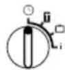
6.2.3 Control knob set to "Setting the clock"
Setting the time
Turn the control knob (n) to Ⓤ
Note: At initial operation or after a longer power failure the symbol Select day +/- is displayed. In this case set the present day, then depress the button ▷(q).
The display (e) shows:
Set clock +/- 12:00
The time is set by depressing the buttons “-” (o) or “+” (p).
Briefly depressing the button alters the time by 1 minute, when the button is depressed for a longer period the time runs faster forward or backward. The seconds are always set to "0". As soon as the button is released the clock will operate normally.
Times before 1200 hrs. (12 noon) can be set faster with the “—” button (o).
When no more alterations are necessary close the lid.
The display (e) shows:
17:53 21.5°C
Setting the day
Turn the control knob (n) to Ⓜ
When Set clock +/- is displayed depress the button ▷ (q). The upper line of the display (e) shows:
Select day +/-
The present day is set by depressing the buttons “−” (o) or “+” (p).
If afterwards you wish to set the time, depress the button □(q).
When no more alterations are necessary close the lid.

6.2.4 Control knob set to "Heating"
Setting the heating programme
The time switch makes it possible to automatically switch on the heating system up to three times a day at a pre-determined time and to automatically switch it off three times a day a pre-determined time.
Those times can be determined individually for each day.
It is also possible to set the same times for each day.
To make programming more effective it is useful to fill in the heating times into the table provided (see chapter 10). The heating programme which is used for most days of the week (also applicable if the times deviate slightly) should be filled in for all days in the first step. The deviating times can later be effortlessly altered.
Turn the control knob (n) to ☐ The display (e) shows:
Select day +/-
Depress the button “—” (o) or “+” (p). All days (or the present day) is displayed in the upper line.
In the setting All days both “heating operation” and “economic operation” will start at the respective times each day.
If only one day of the week (e.g. Thursday) was selected, the set programme for this day always starts at the pre-set time on this day, i.e. each Thursday both “heating operation” and “economic operation” will start at the set times.
One single day can be set by depressing the buttons “−” (o) or “+” (p).
Between Sunday and Monday All days is displayed.
The heating times can be set for the displayed day/all days. For this, depress the button ▷(q).
The display (e) shows:
- Start heating 6:00
The required first starting time for heating is set by depressing the button “−” (o) or “+” (p). Briefly depressing the button alters the starting time by 10 minutes, when the button is depressed for a longer period the time runs faster forward or backward.
When the required starting time is selected depress the button □(q).
Now the respective first starting time for economic operation must be set.
The display (e) shows:
- Start econom. 22:00
The required first starting time for economic operation is set by depressing the button “−” (o) or “+” (p).
Briefly depressing the button alters the starting time for economic operation by 10 minutes, when the button is depressed for a longer period the time runs faster forward or backward.
As soon as the required starting time for economic operation is selected depress the button ▷ (q).
The display (e) shows:
- Start heating --:--
Note: --: means that this starting time was not programmed, i.e. only one starting time for heating operation and one for economic operation is programmed at initial operation (factory pre-setting) or after a longer power failure.
If required, the second starting time for heating operation can now be set as described above, in the chapter “setting the first starting time”.
For the second starting time for economic operation, as well as for the third starting times for heating and economic operation (if required), please proceed as before.
In case that certain starting times are not required, depress the button ▷(q) without making any alterations.
If a displayed starting time is to be cancelled, briefly depress the cancel button C (r) with the tip of a pen. The display shows -:- .
When the required starting times are programmed depress the button □(q).
The display shows Select day +/-. Now select a day as described above and enter the respective times.
Note: If the programme for one single day was altered after having programmed all days of the week, the display shows -- at all starting times when the programme "All days" is recalled. If one starting time is now altered for all days of the week, the original programme for the various days is deleted and must be re-programmed as described above.
The various starting times for one day do not have to be entered in chronological sequence. In the mode Select day +/- the regulator arranges the starting times independently.
You can check the programmed starting times by proceeding as described above, but without depressing “−” (o) or “+” (p).
If the heating operation is to exceed midnight, the last economic operation is ignored. Enter this starting time as first starting time for economic operation on the following day. The regulator recognises the correct sequence of the starting times although the first starting time for heating operation is set to a later hour than the first starting time for economic operation.
Should there be a day on which no heating operation is required (permanently, e.g. office which is not busy on Sundays), please enter the required starting time for economic operation (if necessary, the day before) and cancel all further starting times up to the time you wish normal heating operation to commence.
If on one day of the week continuous heating operation is required, please enter the required starting time for heating operation (if necessary, the day before) and cancel all further starting times up to the time you wish economic operation to commence.
If you wish to carry out extensive alterations to the programme, it might be better to start off with the programme pre-set by the factory.
Proceed as described above to delete all individually set starting times, until the display shows Select day +/-. Briefly depress the cancel button C (r).
After this, the programme pre-set by the factory reappears (for all days: 1^st starting time for heating operation 06:00 hrs; 1^st starting time for economic operation 22:00 hrs, further starting times –:-).
When no more alterations are necessary close the lid.

6.2.5 Control knob set to "Holiday"
Setting the period of absence
Turn the control knobr (n) to ☐The display (e) shows:
Days absent */- 0
The number of days absent is set by depressing the buttons “−” (o) or “+” (p).
Briefly depressing the button alters the number of days absent by 1 day, when the button is depressed for a longer period the displayed days run faster.
Note: The present day must be entered as a day absent, i.e. the regulator starts with the holiday programme immediately. The day of return should only be entered if no heating operation is required for that day!
Example: You would like to leave your house for a two weeks' holiday. You leave the house Saturday afternoon. Return is planned for Saturday, two weeks later, and you would like the house to be heated by then.
If you enter the number of days absent shortly before leaving, the number entered must be "14" (Saturday, Sunday, ... Thursday and Friday, since on the Saturday you return you want the regulator to switch the heating system on as usual.
After closing the lid, the display (e) shows:
14 days absent
17:53 16.5°C
The regulator immediately regulates to the temperature set with the control knob (m) . The remaining days until you return are always displayed. After the set number of days (at midnight) the regulator automatically terminates economic operation and returns to automatic operation.
If you would like to carry out further alterations do not yet close the lid.
Please note that the temperature set with the control knob (m) should be harmless to your pets, plants, etc. for the entire course of your absence.
If you intend to return to your house in the morning, it might be better to start heating shortly after midnight instead of waiting for first heating operation in the morning. In this case, depress the button □(q). after having set the number of days absent. The display shows: "Automatic +/-". Now you can set the operating mode required on return with the button "+" (p) or "-" (o), either to continuous heating operation or to automatic operating mode. If you have selected continuous heating operation, the temperature is regulated to the value set with the control knob ⚙(k), beginning at midnight before your return. Do not forget to depress the button ⚙(g) after your return in order to terminate continuous heating operation.
In case that the holiday operating mode should be terminated early, it is possible to either briefly depress the button ⚙(g) twice, or to set the number of days absent to "0" as described above.
Continuous heating operation for several days can also be programmed by setting the number of days as described above and turning up the economic temperature to the required value with the control knob (m) .

6.2.6 Control knob set to i
Having the set values displayed
Turn the control knob (n) to the position i. The upper display line (e) shows the present day.
If the button □(q) is depressed, the following group is displayed. Each value in the group (if entered) is displayed for 5 seconds before the regulator moves to the next value. If you wish to have the next value displayed faster, depress the button (p).
If you wish to have the value displayed for a longer time, briefly depress the button “—” (o) and the display keeps showing this parameter.
By depressing the button ▷(q) the display moves to the next parameter after 5 seconds.
In the first group, the following general values are dis-played (e) in a five-second-time, non-existing values are not considered:
| Display example(5-second-time sequence) | Parameter description |
| Temperatures | Title of the first group |
| Room temp. here21.5 °C | Measured room temperature at the regulator “here” is only displayed if an external sensor (accessory) is connected. |
| Room temp. remote21.0 °C | Measured room temperature at the external sensor (accessory). |
| Room temp. set21.5 °C | The set temperature with which the regulator is operating. |
In the second group the values of the heating programme are displayed in a five-second-time, values which were not entered are not considered::
| Display example(5-second-timesequence) | Parameter description |
| Heating program | Title of the 2^nd group |
| Thursday | Heating programme for this day (or All days) |
| 1. Start heating6:00 | Set 1^st starting time for heating operation for the day |
| 1. Start econom.9:00 | Set 1^st starting time for economic operation for the day |
| 2. Start heating11:30 | Set 2^nd starting time for heating operation for the day |
| 2. Start econom.13:00 | Set 2^nd starting time for economic operation for the day |
| 3. Start heating17:30 | Set 3^rd starting time for heating operation for the day |
| 3. Start econom.22:00 | Set 3^rd starting time for economic operation for the day |
| Friday | Heating programme for the next day etc. |
After this the automatic display starts from the beginning and continues until the control knob (n) is turned to another position or the lid is closed.
Setting the language
Turn the control knob (n) to the position i.
Depress the button “—” (o) and keep it depressed until the following is displayed:
$$ \text { Sprache } + / - $$
Set the required language with the button “+” (p) or “−” (o).
Available languages:
• German/Deutsch • Turkish/Türkce
- English • Polish/Po polsku
• Dutch/Nederlands • Czech/Cesky
• Spanish/Espanol • Slovak/Slovensky
• Italian/Italiano • Hungarian/Magyar
- French/FRANCAIS - Slovenian/Slovensko
- Portuguese/Portugues • Croatian/Hrvatski
- Danish/Dansk - Lettish/Latviski
- Greek/ELLINIKA - Romanian/Romaneste
When no more alterations are necessary close the lid.
6.3 The “3 ^rd operating level” or “service level”
(Only for experts)
The “3 ^rd operating level” or “service level” for the expert becomes accessible when the control knob (n) is set to the position and the button ▶ (q) is depressed for longer than 5 seconds. Non-existing values are left out.
| Display example | Parameter description | Setting |
| Room sensor +/- 21.3 °C | Calibrating the built-in sensor | The dis-played value can be altered with the button “-” (o) or “+” (p) in steps of 0.1 K by max. ±3 K |
| Rem. sensor +/- 21.4 °C | Calibrating the external sensor (accessory) | |
| Econom. temp.+/- 14.6 °C | Calibrating the displayed value to scale settingControl knob (m) | |
| Heating temp.+/- 19.7 °C | Calibrating the displayed value to scale settingControl knob (k) |
With the button □(q) the next parameter is displayed. If the button □is depressed again when “Heating temp. +/-” is displayed the “service level” is left.
Note: It is important to know that the sensors must not be influenced by external heating sources (body heat) before calibration. As soon as the lid is opened the measured values of the sensors are recorded for calibration.
In order to cancel a calibration, the cancel button C (r) must be briefly depressed in the "service level" when the respective value is displayed. Now the original value is reactivated.
When no more alterations are necessary close the lid.
6.4 Operating reserve
The time switch has an operating reserve of approx. 2 hours after having been in continuous operation for at least one day. In case of a power failure the display is no longer functioning. If the power supply returns within the operating reserve, the display of the time, and of the starting times for heating and economical operation returns.
Take care that the power supply is never interrupted for longer than 2 hours (do not switch off the heating system in the summer but select a low temperature at the regulator; see chapter 6.1.2 tips for continuous heating).
6.5 Setting the summer and the standard times
Proceed as described in the chapter ⚙setting the time"!
Do not alter the settings "start heating" and "start economical operation"!
6.6 Brief operating instructions
The brief operating instructions where all important functions are briefly described are in the compartment at the right side of the base (illustration 2)
6.7 Regulator with connected room temperature sensor RF 1 (accessory)
If a room temperature sensor RF 1 is connected the built-in sensor in the regulator is ineffective. Now the temperature conditions surrounding the external room temperature sensor are decisive for temperature regulation.
Use the room temperature sensor RF1 when the mounting location of the regulator has unfavourable measuring conditions which are not applicable for the entire house e.g. in-solation, a tiled stove nearby, etc.
6.8 Regulator with connected remote control switch (by customers)
With this remote control switch (not included in the delivery range) the heating system can be activated from afar.
The most common application is probably the use of a telephone commander. With this appliance the heating system can be switched on via any telephone with aid of a personal identification code.
Before leaving the house the regulator is set to the mode required at return (automatic operation mode or continuous heating operation).
Then the switching contact of the remote control switch is deactivated, the regulator is operating in the economical operating mode. The respective red control light ⚙(1) is off.
The display (e) shows:
Remotely locked
17:53 16.5°C
If the switching contact is activated (e.g. by a coded telephone signal) the regulator operates in the pre-set operating mode.
It will be warm in the house late at night/ early in the morning if the regulator is set to the position (continuous heating) (g) before leaving the house, and the switch is deactivated afterwards. Do not forget to set the regulator back to "automatic operating mode" after returning to the house.
If the house is left for a longer period you should consider that it could become a lot cooler (walls could cool down etc.) and therefore it will take a longer time to heat up. Do switch the heating system on in time.
6.9 Reprogramming
If you would like to carry out extensive alterations to the programme it might be better to set the regulator back to the programme preset by the factory and to re-enter all starting times.
Turn the control knob (n) to the position ∥ until the display (e) shows Select day +/- then briefly depress the cancel button C (r).
If all settings, even the time and the day (and the display language) are to be deleted together with the starting times, the cancel button C(r) must be depressed for longer than 10 seconds.
7 Regulator Malfunction Message
Malfunction remote indicator
(not available with all heating systems)
For heating equipment with Bosch Heatronic, a malfunction in the heating equipment is routed to the regulator.
In case of a malfunction of the heating unit the control light ⚙Heating” (I) indicates.
The display (e) shows:
Check System
17:53 18.0°C
Note: In this case please proceed as stated in the operating instructions of the heating unit or contact your local expert for heating systems.
8 General Information
... and hints on saving energy:
When the regulator settings are altered the regulator reacts with a time lag. Every 20 seconds the processor compares all desired and actual values and carries out all necessary corrections with the necessary speed.
The room in which the room temperature regulator is mounted (control room) determines the temperature for all other rooms.
i.e. the room temperature in the control room acts as a control input for the entire heating network.
For this reason all thermostat regulated radiators located in the control room must be opened completely at all times. Otherwise the thermostat valves would reduce the heat supply although the regulator constantly requires more heat (see also chapter 4.1).
If in the adjoining rooms a lower temperature is wanted or if the radiator should be turned off completely, the (thermostatic) radiator valves must be set accordingly.
Since the room where the room temperature regulator is mounted acts as a control room, any external heating sources (e.g. insolation, tiled stove, etc.) can result in insufficient heating of the remaining rooms (the radiators stay cold). In order to avoid this the room temperature sensor RF 1 can be used according to the notes in chapter 2.2, chapter 5.1 and chapter 6.7.
When the room temperature is reduced during the day or during the night a lot of energy can be saved.
If the room temperature is reduced by 1 K (°C) this can save up to 5% of energy.
It is not recommended to let the temperature of daily heated rooms drop below +15°C. When the room is heated up again the comfortableness is diminished by the walls which are cooled down. So if one wants a real comfortable room temperature the regulator must be turned up and so a lot more energy is used up than is in case of an even heat supply.
If the building has good thermal insulation it is possible that the set economic temperature is not reached. But even in this case energy is saved since the heating system is not activated.
In this case the starting time for economical operating mode can be set earlier.
Do not let windows stand ajar for airing the rooms since this would constantly withdraw heat from the room without improving the air in the room considerably. Do avoid continuous airing!
It is better to air the room briefly but properly (open the windows completely).
Set the temperature regulator to a lower value during airing.
9 Elimination of malfunctions
| Malfunction Cause | Elimination | |
| the set room temperature is not reached | thermostat valve(s) are installed in the room where the regulator is mounted | have the thermostat valve replaced by a hand valve or completely open the thermo-stat valve(s) |
| the flow temperature of the heating unit is set too low | set the flow temperature to a higher value | |
| the pre-set room temperature is exceeded | the mounting location of the regulator is inappropriate, e.g. outside wall, close to a window, draught,... | select a more appropriate mounting location (see chap-ter mounting) or use an exter-nal temperature sensor (accessory) |
| too high variation in room temperature | temporary influence of external heating sources on the regulator e.g. by insola-tion, room lighting, TV, fire-place, etc. | select a more appropriate mounting location (see chap-ter mounting) or use an exter-nal temperature sensor (accessory) |
| rise in temperature instead of reduction | the time of day is set incor-rectly at the time switch | check the setting |
| too high room tempera-ture in economic operat-ing mode | high regenerative capacity of the building | select an earlier starting time for economic operating mode |
| wrong or no regulation wrong | wiring of the regulator check | the wiring according to the circuit diagram and correct if necessary |
| no display or the display does not react | very short power failure switch | off and on the heating unit main switch |
Zile conceded. +/- 0
Individual Heating Times
7
8
9
10

11


BOSCH
Bosch Thermotechniek B.V.
Postbus 379
7300 AJ Apeldoorn
Tel: +31 (0) 55 - 543 43 43
Fax: +31 (0) 55 - 543 43 44
www.boschcvketels.nl
infott@nl.bosch.com

- Deutsch
- Français
- Safety Instructions
- Application
- Scope of delivery
- Accessory
- Technical Data
- Mounting
- Selecting the mounting location
- Mounting the regulator
- Mounting the accessories
- Mains Connection
- Accessory mains connection
- Operation
- The "1 st operating level"
- Control knob ⚙(k)
- The operating conditions
- Automatic operating mode
- Button
- "Continuous heating mode" (g)
- "Economical operating mode" (h)
- The "2 nd operating range"
- Control knob C "economic temperature" (m)
- General information on the timer
- Control knob set to "Setting the clock"
- Setting the time
- Setting the day
- Control knob set to "Heating"
- Setting the heating programme
- Control knob set to "Holiday"
- Setting the period of absence
- Control knob set to i
- Having the set values displayed
- Setting the language
- Available languages:
- The “3 rd operating level” or “service level”
- Operating reserve
- Setting the summer and the standard times
- Brief operating instructions
- Regulator with connected room temperature sensor RF 1 (accessory)
- Regulator with connected remote control switch (by customers)
- Reprogramming
- Regulator Malfunction Message
- Malfunction remote indicator
- General Information
- BOSCH
Brand : BOSCH
Model : TR 200
Category : Thermostat