
NV-U70T - GPS Navigator SONY - Free user manual and instructions
Find the device manual for free NV-U70T SONY in PDF.


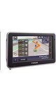
| Product Type | GPS Navigator |
| Brand | Sony |
| Model | NV-U70T |
| Dimensions (W × H × D) | approx. 104.7 × 87.5 × 42.9 mm |
| Weight | approx. 310 g |
| Power Supply | 5 V DC (AC adapter) or 5.2 V DC (car battery adapter); built-in rechargeable lithium-ion battery |
| Display | 3.5-inch TFT LCD (4:3), 960 × 240 pixels (230,400 dots) |
| GPS Receiver | 12 parallel channels |
| Pre-installed Maps | Europe (NV-U70T) |
| Voice Guidance | 15 selectable languages |
| Main Features | Touch screen, RDS-TMC (traffic information), automatic brightness control, battery operation, address search, special destination, favorites |
| Operating Temperature | 5 to 45 °C |
| Battery Charging | Possible only between 5 and 45 °C |
| Maintenance | Replace car adapter fuse with one of same rating; clean surfaces before installation; avoid condensation |
| Safety | Install without obstructing driver's view; do not use while driving; remove device from car to prevent theft and excessive heat |
| Spare Parts and Reparability | Optional accessories: external GPS antenna VCA-41, mount kit NVA-CU3T/CU3, installation kit XA-49FM, European map kit NVD-DU3 |
| General Information | Warranty does not cover loss or deterioration of data; disposal in accordance with WEEE standards |
Frequently Asked Questions - NV-U70T SONY
User questions about NV-U70T SONY
0 question about this device. Answer the ones you know or ask your own.
Ask a new question about this device
Download the instructions for your GPS Navigator in PDF format for free! Find your manual NV-U70T - SONY and take your electronic device back in hand. On this page are published all the documents necessary for the use of your device. NV-U70T by SONY.
USER MANUAL NV-U70T SONY
Personal Navigation System
NV-U70T NV-U50T NV-U50
© 2005 Sony Corporation
2-663-630-12 (1)
Quick Start Guide
GB
- This Quick Start Guide contains instructions for installation, connections and basic operations. For more information, see the PDF manual on the supplied Application Disc.
- Contents of this manual are written for users with knowledge of using the Microsoft® Windows® operating system. For details about computer operation, see the manual for your computer.
- Illustrations in this manual may differ from the actual device.
- Retain this manual in a place where you can refer to at any future time.

Disposal of Old Electrical & Electronic Equipment (Applicable in the European Union and other European countries with separate collection systems)
This symbol on the product or on its
packaging indicates that this product shall not be treated as household waste. Instead it shall be handed over to the applicable collection point for the recycling of electrical and electronic equipment. By ensuring this product is disposed of correctly, you will help prevent potential negative consequences for the environment and human health, which could otherwise be caused by inappropriate waste handling of this product. The recycling of materials will help to conserve natural resources. For more detailed information about recycling of this product, please contact your local Civic Office, your household waste disposal service or the shop where you purchased the product.
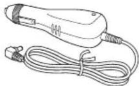
Applicable accessories: Car battery adapter/AC power adapter
No guarantee for lost data or damaged data
Sony does not provide any guarantee for lost or damaged data.
Caution
IN NO EVENT SHALL SONY BE LIABLE FOR ANY INCIDENTAL, INDIRECT OR CONSEQUENTIAL DAMAGES OR OTHER DAMAGES INCLUDING WITHOUT LIMITATION LOSS OF PROFITS, LOSS OF REVENUE, LOSS OF DATA, LOSS OF USE OF THE PRODUCT OR ANY ASSOCIATED EQUIPMENT, DOWNTIME, AND PURCHASER'S TIME RELATED TO OR ARISING OUT OF THE USE OF THIS PRODUCT, ITS HARDWARE AND/OR ITS SOFTWARE.
Welcome!
Thank you for purchasing this Sony Personal Navigation System. Before operating this system, read this manual thoroughly and retain it for future reference.
FEATURING:
- Plug & Play capability
• Pre-installed European map (NV-U70T) - Pre-installed regional map (NV-U50T/U50)
- 15 languages selectable for voice guidance and on-screen display
• 3.5-inch high quality display with touch screen - Advanced 12ch parallel GPS receiver
• High-quality speaker - RDS-TMC (Traffic Message Channel) compatible (NV-U70T/U50T)
- Battery operation
• Auto dimmer function
Table of Contents
Important notice....4
Getting Started 6
Checking the contents 6
Installing the unit. 7
Installing the TMC aerial (NV-U70T/U50T only)....9
Location of controls....10
Turning the unit on 11
Starting up the navigation ..... 11
Receiving GPS signals 11
Basic Operations 12
Menu operations 12
Keyboard operations ..... 12
Route Searching 13
Setting the destination and starting guidance....13
Setting the destination in other ways. . . . . . . 14
Guidance displays 15
System Settings 16
Using the Supplied Software 17
Connecting to your computer.... 17
Software features 18
Additional Information 18
Precautions 18
Note on LCD panel.... 18
Maintenance 18
Notes on unit disposal. 18
Specifications 19
Troubleshooting 20
Resetting the unit 20
Important notice
To avoid the risk of accident or injury, read the following warning before installing and operating the unit.
On handling
- Do not let foreign objects get inside the cradle connector of the unit, as it may cause malfunction.

- Turn the unit off by pressing I/☐, take it out of the cradle, then disconnect the car battery adapter, otherwise car battery drain may occur. Note the following.
- Turning the ignition off does not turn off the unit, which continues to draw power from the lithium-ion rechargeable battery (built-in).
- If your car's cigarette lighter socket is not connected to the ignition switch ACC position, power continues to be supplied to the built-in battery, even if you turn the ignition off.
- Check the CHG indicator at the bottom right of the unit which lights up during charging.

natural_image
Line drawing of a rectangular electronic device with a screen and two ports, no text or symbols present- Do not expose the unit to fire, as it may cause malfunction.
- Do not let water or rain get into the unit, as it may cause malfunction.
- If you leave the unit in direct sunlight, the LCD may darken and not display clearly. This is not a malfunction, and it will return to normal as temperature decreases.
- Note that the built-in battery cannot be charged at temperatures outside 5 - 45^ (41 - 113^) .
- Do not leave the unit in high ambient temperature as the built-in battery capacity will deteriorate, or it will become unchargeable.
On safety
General
- Do not apply excessive force to the unit or cradle as it may fall under the brake pedal, etc., and cause an accident.
- Observe actual traffic regulations, such as one-way streets, while driving with the route guidance.
- Do not watch the unit while driving. It is dangerous and may cause a traffic accident.
- If you need to operate the unit while driving, be sure to stop the car in a safe place before operating.
- Be sure to take the unit out of the car when leaving your car to prevent theft or high temperature damage inside the car.
- When the car battery adapter is not in use, disconnect it from the cigarette lighter socket, as car battery drain may still occur even with ignition OFF.
- Do not allow any liquid or foreign objects to enter the unit.
- Do not place anything other than the specified unit in the cradle.
- Do not connect any accessory (car battery adapter, AC power adapter, etc.) other than those supplied or optional.
- Do not modify the unit.
- Do not disassemble the unit except when disposing of it.
Installation
- Before installing the unit, check your local traffic laws and regulations.
- Make sure you install the unit properly according to the installation instructions. Improper installation may result in fire or electric shock.
- Before installation, be sure to turn the ignition switch to the OFF position or take out the key. Installing the unit with the ignition on may cause the car battery to drain or short circuit.
- Besure to:
- attach the unit to the cradle properly.
- clean the surface of the suction cup and windscreen before attaching. Also, confirm that the suction cup is securely attached to the windscreen after installation.
- warm up the car interior and then install the cradle and unit if ambient temperature is low. The cup suction is affected at high/low temperatures or sudden changes in temperature.
- wipe the windscreen before installation if there is condensation inside the car. Otherwise, the unit or cradle may fall under the brake pedal, etc., and cause an accident.
- Be sure to place the cables where it does not obstruct driving.
- Do not use the unit in a car with the USB cable connected.
- Connect the car battery adapter only to the cradle.
- Do not damage any pipes, tubes, the fuel tank or electric wiring when installing the unit, as fire or accident may result. If you drill a hole in a car panel, make sure that any hidden car parts will not be damaged.
- Do not use or modify any nuts or bolts of critical devices such as steering linkage, fuel supply or braking systems. This can cause fire or an accident.
• Take care to prevent cords or wires from getting tangled or crimped in the moving portion of a seat rail. - For information about the polarity, battery voltage and location of the airbag of your car, please consult your car dealer.
Installing location
- Please install the unit in a safe place where:
- it does not obstruct the driver's view.
- it does not obstruct the operation of the airbag system.
- it does not obstruct the operation of the car, especially the steering wheel, shift lever, or brake pedal.
- it is not subjected to heat/high temperature.
- Please consult a qualified technician or service personnel if you cannot attach the cradle to the car securely.
On GPS
GPS (Global Positioning System) satellites continuously emit signals for positioning anywhere on the earth. As a GPS aerial receives these signals, users can be informed of their location (latitude, longitude and altitude). Information must be received from 3 satellites in order to obtain two-dimensional fixes (latitude and longitude), and 4 satellites are required for three-dimensional positioning (latitude, longitude and altitude). As GPS satellites are controlled by the U.S. Department of Defense, a deliberate margin of error between a few metres (a few feet) and 10 metres (32.8 feet) exists. As a result, the GPS navigation system may include an error of between 10 metres (32.8 feet) and about 200 metres (656.2 feet), depending on the circumstances.
As GPS information is obtained using signal from satellites, it may be impossible or difficult to obtain the information in the following locations:
- Tunnel or underground

• Under a highway
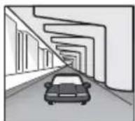
- Between high buildings

- Between tall trees with dense foliage

After the initial installation, park your car in a safe, open place (no high buildings, etc.) for up to 20 minutes to allow for GPS signals to be received before using the navigation system. The system requires signals from a minimum of 3 GPS satellites to calculate the current car position properly.
Note
It takes time to receive a GPS signal when switching the unit ON after switching OFF the main power, after the built-in battery is fully discharged, or after resetting the unit.
On the software
Read the following conditions carefully before use.
• Copyright laws prohibit reproducing the software or the software manual in whole or in part or renting the software without the permission of the
- In the event a problem occurs with this software as a result of defective manufacturing, Sony will replace it at Sony's option or issue a refund. However, Sony bears no other responsibility.
- The software provided with this product cannot be used with equipment other than that which it is designated for use with.
- Please note that, due to continued efforts to improve quality, the software specifications may be changed without notice.
- Roads and names on the map may differ from actual roads and names.
- The warranty does not extend to an exchange or refund due to some typographical errors and omissions, or any other discrepancy in layout found in the software.
- In no way may the map data be copied and used, in whole or in part, without permission of the copyright holder.
- Contents are subject to change without notice. By using the unit, you are agreeing to be bound by the above.

Getting Started
Checking the contents
Check the package contents.
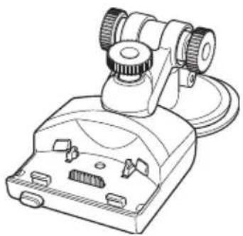
- Main unit (1)

natural_image
Line drawing of a rectangular electronic device with two circular ports and a central screen (no text or symbols)• Crad1(el)*

natural_image
Line drawing of a mechanical device with gears and a base (no text or symbols)• Car battery adapter (1)
natural_image
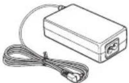
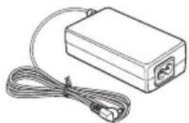
Line drawing of a handheld electric shaver with coiled cable and power plug (no text or symbols)- AC power adapter (1)

natural_image
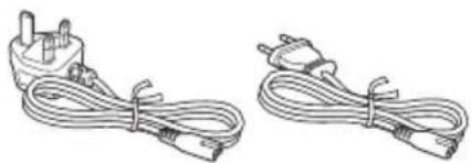
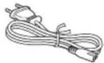
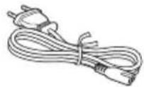
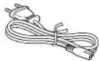
Illustration of a rectangular electronic device with cables and connectors (no text or symbols)- AC power cable(s)
- For NV-U70TW/U70TC*2 (2)
natural_image
Two types of electrical plug wires with connectors, no text or symbols visible- For NV-U50TG/U50G*2 (1)

- For NV-U50F/U50D/U50I/U50A/U50B/U50S/U50N*2 (1)

- USB cable (1)

natural_image
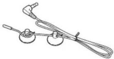
Line drawing of a broadband cable with two connectors (no text or symbols)• TMC antenna (aerial) (1)/suction cups (2) (For NV-U70T/U50T)

natural_image
Line drawing of a medical or laboratory device with three circular components and a coiled cable (no text or symbols)- Adhesive tape (1)
- Pad (1)
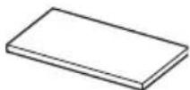
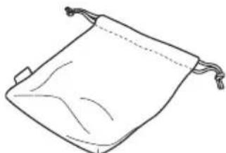
- Carrying pouch (1)

natural_image
Simple line drawing of a folded paper or bag with a handle and rope (no text or symbols)- Application Disc (CD-ROM) (1) (For NV-U50T/U50)

• Application Disc (DVD-ROM) (1) (For NV-U70T)

- Quick Start Guide (1)
- Warranty card (1)
- User registration card (1)
• END-USER LICENSE AGREEMENT (1)
*1 NV-U70T/U50T have a TMC aerial jack on the left side.
*2 The model names are written on the label on the bottom of the main unit.
Installing the unit
About the main power switch
Before installation, switch on the main power by sliding the POWER switch to the ON position.
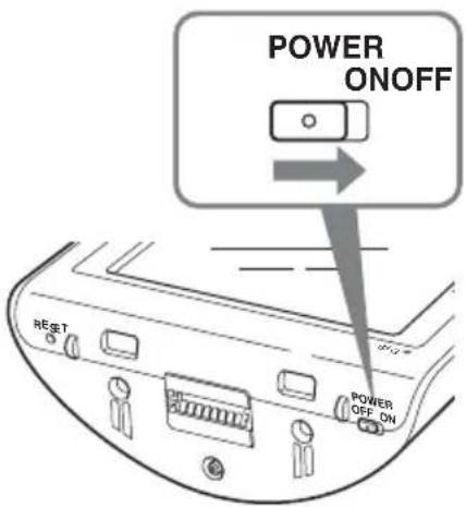
Thereafter, you can turn the unit on/off by pressing I/ ^① on the top right of the unit.
Notes
- Keep main power on unless the unit is not to be used for more than 3 months.
- If you switch off the main power, it may take time to receive GPS signals when switching on again.
About the suction mount
Before you start, choose a position on the windscreen that is clearly visible to the driver without obstructing the road view, and make sure all surfaces are clean and dry.
The optional cradles NVA-CU3T/CU3 can also be installed following the steps below.
Notes
• Install the unit in a safe place where it does not interrupt the GPS signal.
- Detach and reattach the cradle regularly as cup suction is affected by high/low temperature, extended use, etc.
- Be sure to keep a distance between the cradle and dashboard when installing.
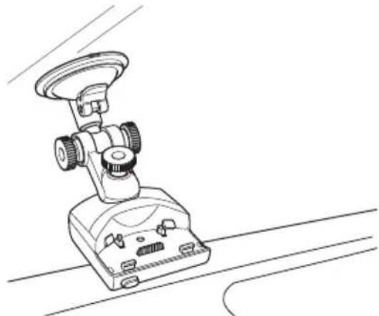
1 Attach the cradle on the windscreen. Figure example of completed cradle installation
natural_image
Line drawing of a mechanical device with a circular head and adjustment knobs (no text or symbols)Follow steps ① - ③ to complete.
① Clean and dry the surface of the suction cup.
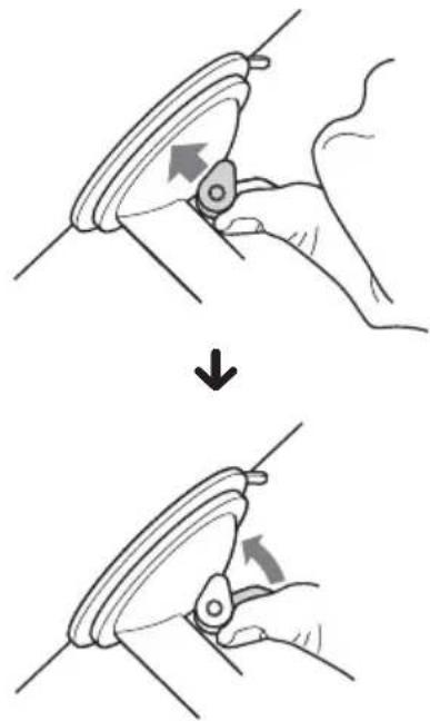
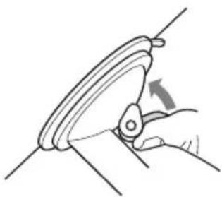
②Press the centre of suction cup firmly against the windscreen to remove the remaining air inside it, then press the lever.
natural_image
Illustration showing a hand holding a circular object with an arrow indicating rotation, before and after a change (no text or symbols present)③Holding the left knob*, loosen the right knob and set the approximate vertical angle, then retighten. *The left knob does not turn.

If you want to fix the cradle on the windscreen permanently
The suction cup is affected in high/low temperatures and may come off. If you want to fix the cradle on the windscreen permanently, use the supplied adhesive tape on the suction cup.
If the bottom of the cradle touches the dashboard
Attach the supplied pad for protection.
Cut the pad to the appropriate size before attaching.
Note
The adhesive tape is difficult to remove once applied.
2 Connect the cradle to the car cigarette lighter socket.
① Plug the car battery adapter into the DC IN 5.2V jack at the rear of the cradle.

natural_image
Technical illustration of a microscope with an inset showing a cable being inserted (no text or symbols present)②Insert the other end of the car battery adapter fully into the car cigarette lighter socket.
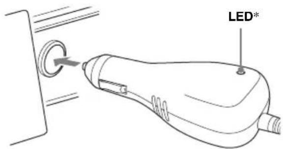
*Lights up when you turn the ignition on after installation.
Note
Depending on the size or shape of the cigarette lighter socket, connection may not be possible.
3 Align the 2 slots on the underside of the unit with the tabs on the cradle, then push to snap the unit into place.

natural_image
Technical line drawing of a microscope with mechanical components and directional arrows indicating motion (no text or symbols)Be sure the unit is securely locked in the cradle (2 clicks).

4 Loosen the centre knob, fine adjust the angle so you can view the monitor properly, then retighten.

Tip
You can also connect the unit to an outlet using the supplied AC power adapter.

To detach the unit from the cradle
1 Holding the unit, press the RELEASE button of the cradle.
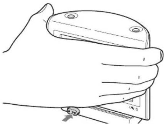
The unit pops out of the cradle.
2 Take the unit out of the cradle.
Installing the TMC aerial (NV-U70T/U50T only)
Install the TMC aerial to obtain traffic information from RDS-TMC (Traffic Message Channel).
1 Plug the TMC aerial cord into the TMC aerial jack on the left side of the cradle.

natural_image
Line drawing of a vacuum cleaner with attached cable and connector (no text or symbols)2 Attach the end suction cup to the windscreen, then attach the other suction cup so as the cord forms 2 straight lines.

natural_image
Line drawing of a car interior with a mounted sensor and steering wheel (no text or symbols)Location of controls
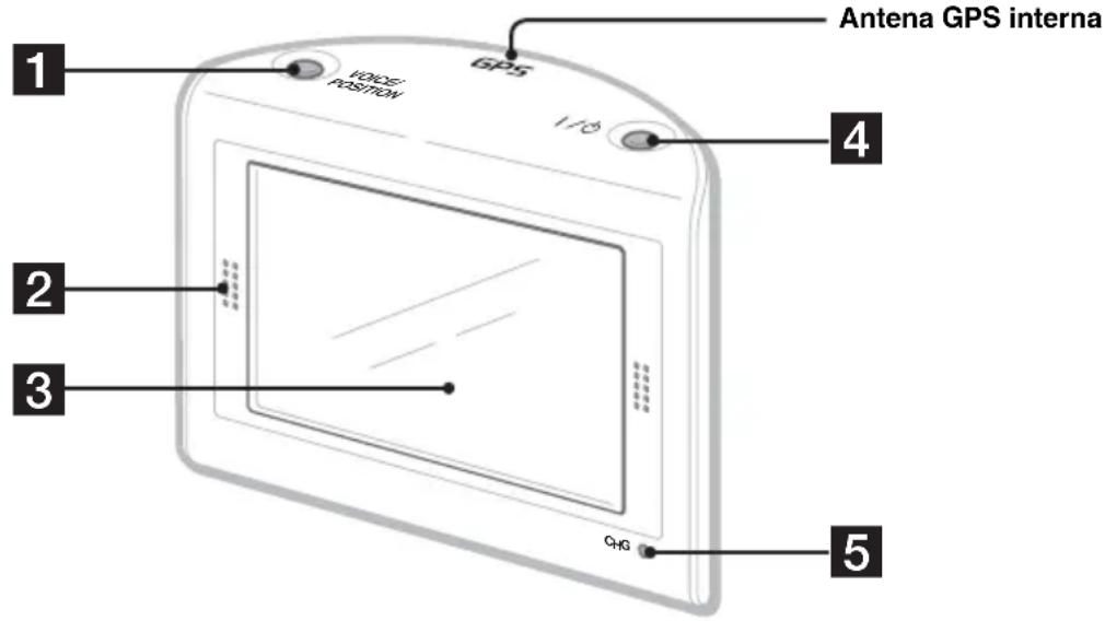
Front:

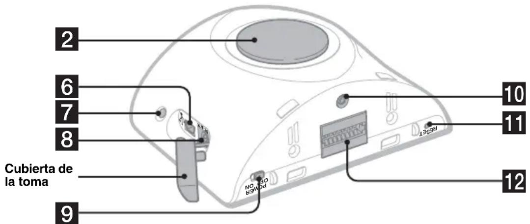
Rear:

Refer to the pages listed for details.
1 VOICE/POSITION button
During route guidance:
To hear the next voice guidance.
In map scrolling mode:
To show your current car position.
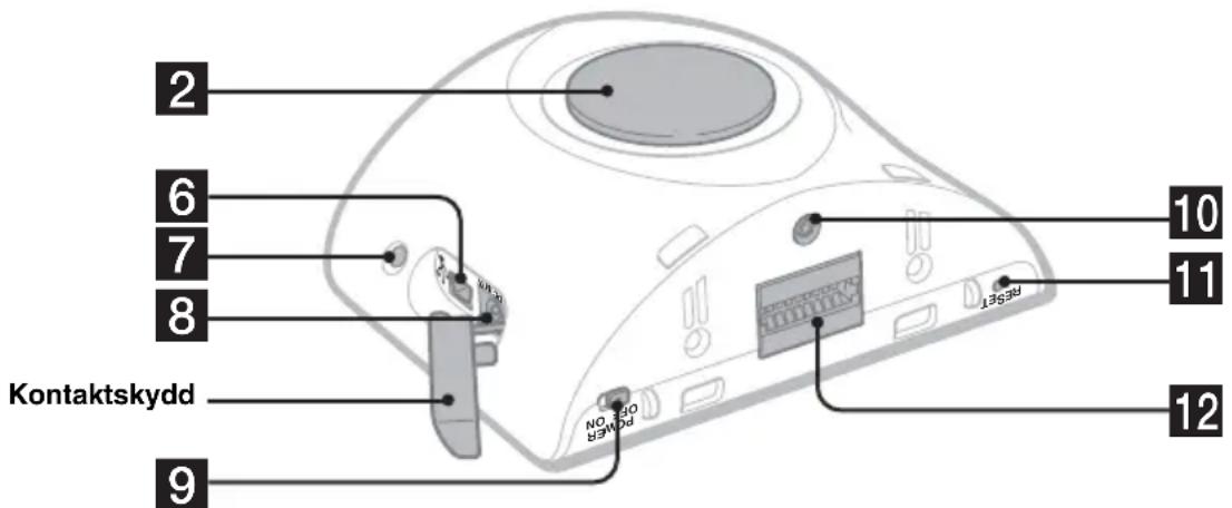
2Speaker
Outputs guidance and warnings.
3 Display window/touch screen
4 I/⏻ (on/standby) button 11
To turn the unit on/off.
5 CHG (battery charge) indicator
Lights up in red while charging.
6 USB jack 17
To connect to a computer with the USB cable.
7 Auto dimmer sensor
For details on auto dimmer function, see the supplied PDF manual.
8 DC IN 5V jack
To connect to the AC power adapter.
9 POWER switch 7,20
To turn the main power on/off.
10 External GPS antenna (aerial)\* jack
11 RESET button 20
12 Cradle connector
* Not supplied
Turning the unit on
Check that the POWER switch on the bottom right of the unit is in the ON position beforehand (page 7).
1 Press I/⏻.

natural_image
Line drawing of a rectangular electronic device with a screen and two ports, no text or symbols presentTo turn the unit off
Press I/☐.
The unit enters standby mode for minimum power consumption.
Note
Be sure to take the unit out of the cradle and disconnect the car battery adapter when the unit is not in use to prevent car battery drain.
Starting up the navigation
1 After turning the unit on, touch the desired language.
The warning display appears.
2 Read the warning display, then touch "Agree."
The tutorial displays appear.
3 Touch ▼ to proceed.
The top menu appears.
Receiving GPS signals
After the initial installation, park your car in a safe, open place (no high buildings, etc.) for up to 20 minutes to allow for GPS signals to be received before using the navigation system. The system requires signals from a minimum of 3 GPS satellites to calculate the current car position properly.
You can check the GPS status on displays.
GPS status indicator*

* Lights up in bright green when signal reception is sufficient for navigation. Lights up in dark green when signal has been lost.
Basic Operations
Common procedures to operate the system are explained.
General operations can be performed on the touch screen. Touch the displayed icons with your finger gently.
Note
Do not press the display with excessive force, or use any sharp article, such as a pen, etc., to tap on the display.
Menu operations
You can set items in the menu by the following procedures.
1 Show the top menu.
In the map display, touch the map. In the menu display, touch to show the map, then touch the map.

2 Touch "Settings," then touch a desired item.

3 Touch ▲/▼ to scroll the list, then touch a desired setting item.
E.g.: Volume setting display

4 Make the desired setting.
Touch and select the desired setting or input characters.
During menu operation:
To return to the previous display, touch . To cancel the menu selection, touch (the current car position display appears).
Note
The items on the menu and setting operations differ depending on the selected menu item.
Keyboard operations
The keyboard display appears when you need to enter text.
You need only enter characters in upper case, as the system automatically converts them to appropriate characters. You can enter special characters when necessary (e.g. when naming a saved destination, etc.).
Mobile phone keyboard display
Candidates
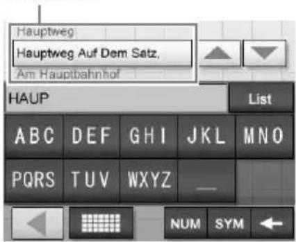
| enter an alphabetical character | the relevant key (e.g. “ABC”) repeatedly until the desired character is highlighted in the line above the keyboard. |
| enter a number “NUM” to switch to the number keyboard, then the desired number key; and “ABC” to switch back. | |
| enter a space “_” | |
| delete a character “←” | |
| select a candidate | ▲/▼ to scroll the list, then the desired candidate to confirm. |
| see the list of all candidates | “List” |
You can select either a mobile phone keyboard or a character keyboard (alphabetical) for the keyboard display.
Touch to switch to character keyboard.
The character keyboard is used in the same way as the mobile phone keyboard, except when:
- entering a character (touch the desired character key).
- entering a special character (touch "SYM" to switch to the special character keyboard; touch "ABC" to switch back).
Touch to switch back to the mobile phone keyboard.
Route Searching
The system searches for routes automatically after setting the destination.
Before starting, check that GPS signals are sufficient for navigation (page 11).
Setting the destination and starting guidance
The procedure for searching for the route and starting route guidance is explained.
As an example, setting the destination by the address is introduced here.
For details on setting the destination in other ways, see “Setting the destination in other ways” on page 14.
For your safety, park your car in a safe place, then enter the destination information before starting a journey.
1 Show the top menu.
In the map display, touch the map. In the menu display, touch to show the map, then touch the map.
2 Select "New Destination" → "Navigation."

3 Select the desired country by touching the "Country" entry field.
Only countries included in the current map data are selectable.
4 Select "Address."

5 Input the address details.
For details on how to input characters, see “Keyboard operations” on page 12.
Touch the respective entry field to input the items below.
"Town or Postcode"
Input the town name or postcode.
"Street"/"-"
Input the street name, and house number (if known).
If no house number is available, the “−” field is deactivated.
"Intersection"
Input the crossroad name if you want it as the destination point.
6 Select "Start navigation."
The route option selection display appears.
For details on selecting route options, see the supplied PDF manual.
7 Select "Start navigation" again.
The map display appears, the route is calculated, and route guidance starts.
Setting the destination in other ways
You can also set the destination and search for routes by the following methods.
From the top menu, select the items in the following order, then “Start navigation” (if necessary).
For details, see the supplied PDF manual.
Search nearby
Searches for routes to a POI, such as restaurant, hotel, etc., near the current car position.
Home
Searches for routes to your home when it is registered.
“New Destination” → “Home”
Point of interest
Searches for routes to a POI, such as restaurant, hotel, etc., by selecting the category(ies) and correct destination from the list.
Select “New Destination” → “Navigation” →
“Point of interest,” then the following options which allow you to specify the search area.
"---nearby"
Searches within the specified radius of the centre of the map.
“---nationwide”
Searches within the specified country.
“---in a town”
Searches within the specified town.
Select on map
Searches for routes by setting the destination directly from the map display.
“New Destination” → “Navigation” → “Select on map”
Recent destinations
Searches for routes to recently searched destinations.
“New Destination” → “Navigation” → “Recent destinations”
Favourites
Searches for routes to a saved destination point.
“New Destination” → “Navigation” →
"Favourites"
Guidance displays
Once a route has been calculated, visual guidance navigates you to the destination along with audio guidance.
Information on map tool menu
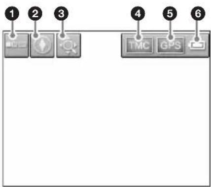
①To show/hide tool menu.
②To switch the map direction (north up/heading up) of the 2D map.
③To switch to map scrolling mode.
④To view TMC information.*
⑤To view detailed GPS information.
⑥Indicates battery condition.
* NV-U70T/U50T only. Lights up in bright orange during reception. Lights up in dark orange during no reception.
2D map display
Straight-ahead driving

Approaching an intersection

Approaching an intersection (closer)
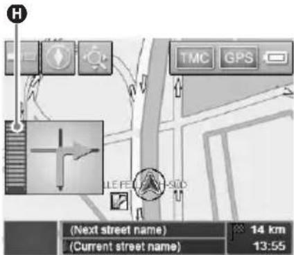
Next guidance immediately after intersection

A Current position
B Distance to next turn
©Next direction
DCurrent street name
ENext street name
FETA (Estimated Time of Arrival)/Distance to destination
GNext turn instruction
HBar indication of distance to next turn
Instruction after next
3D map display
You can set the 3D map display in the setting menu (page 16).
View route display
You can view the entire route to the destination. To display, from the top menu, select "Route" → "View route."
continue to next page →
Map scrolling mode
You can switch to map scrolling mode from map display by touching, whether during route guidance or not.
In map scrolling mode, the cross-hair is displayed on the map, and you can drag the screen to scroll the map.

Touch -/+ to adjust map scale.
Place the intersection of the cross-hair on a desired point, then touch to show the map scrolling mode menu, where you can set the point as a destination, etc.
Touch to return to the current car position display.
System Settings
Various settings related to the system and memory are configurable.
From the top menu, select "Settings," then the desired item below to make each setting. For details, see the supplied PDF manual.
Volume
To adjust the voice guidance volume.
Note
When the unit is powered by the built-in battery, maximum available volume is 70 %, even if set higher (80 %, etc). When it is powered using the car battery adapter or AC power adapter, this does not apply.
Select map
To select a map stored in the unit.
Map information
To show/hide the information bar (displayed at the bottom of the map), POI icons, and street names on the map.
Route information
To show/hide ETA (Estimated Time of Arrival) and distance to final destination on the map.
Signpost information
To show/hide signposts indicating motorway/ highway exits*1 on the map.
Light sensor
To adjust the sensitivity of the auto dimmer sensor.
Graphical look
To set the brightness and map colour.
Touch screen calibration
To calibrate the contact position of the touch screen.
Auto mode
To select the default map display (2D or 3D); automatically change the map scale depending on the driving speed (configurable for 2D and 3D respectively); select the default map direction for 2D map display (north up or heading up).
Routing options
To select the route search preference (time-optimized or distance-optimized); permit/avoid motorways, ferries and toll roads on route.
Itinerary
To automatically proceed to the next destination after reaching the previous destination.
Time zone
To select the time zone of the current region; switch between daylight saving time and standard time.
Although the current time is automatically set by GPS, the time zone needs to be set for ETA (Estimated Time of Arrival) to be displayed accurately.
Format
To select 12/24-hour clock indication; select the distance unit (kilometres/miles).
Select language
To select the desired language for on-screen display and voice guidance.
Home address
To register your home address.
Radio muting ^*2
To attenuate the radio sound.
Demo mode
To start the demonstration.
Product information
To display unit information, such as name, version, etc., and tutorials.
*1 Displayed only if contained in the map information.
*2 Only if the optional Car Install Kit XA-49FM is connected to the "Radio muting" jack of your car audio.
Note
Warnings given according to map information may not always be correct due to road works, etc. Traffic situations and road regulations take absolute precedence over information given by the navigation system.
Using the Supplied Software
Significant functions using the supplied software are introduced here.
For details, see the supplied PDF manual.
Operating system requirements
• OS: Windows 98SE/2000/ME/XP
• CD-ROM/DVD-ROM drive
- USB port
• 150 MHz CPU speed minimum (recommended)
Connecting to your computer
1 Connect the unit to an outlet using the AC power adapter and the AC power cable.
2 Connect the unit to your computer with the USB cable.
Connect the small connector of the USB cable to the USB jack on the unit, then the large connector to a USB port on your computer.

natural_image
Line drawing of a cable inserted into a device with two connectors (no text or symbols)Notes when transferring data
During transfer, do not
– disconnect the USB cable or the AC power adapter.
- turn off the main power of the unit, enter unit standby mode, or reset the unit.
- shut down the computer, enter computer standby mode, or restart the computer.
If you want to cancel transferring mid-way, click the cancel button on the computer screen.
continue to next page →
Software features
Install PC connection software
PC connection software (ActiveSync) can be installed.
Backup and Restore pre-installed map (NV-U50T/U50 only)
The map data pre-installed in the unit can be backed up on your computer and restored to the unit, in case of accidental deletion, etc.
Map Manager
Map data can be added to the unit from the supplied or optional DVD-ROM. When adding, you may need to delete unnecessary map data from the unit to free up memory space.
Language Manager
Language data for on-screen display and voice guidance can be added to the unit from the supplied CD-ROM/DVD-ROM, and unnecessary language data can be deleted from the unit.
Read the manual
You can read the manual in PDF format.
Support link
Easy access to the Sony navigation support site is available.
Visit this site for technical support, such as software and firmware updates, FAQs, etc.
Re-install application
The navigation software pre-installed in the unit can be re-installed from the supplied CD-ROM/DVD-ROM, in case of accidental deletion, etc.
Additional Information
Precautions
If your car has been parked in direct sunlight, allow the unit to cool off before operating it.
Moisture condensation
On a rainy day or in a very damp area, moisture condensation may occur inside the display of the unit. Should this occur, the unit will not operate properly. In such a case, slide the POWER switch on the bottom right of the unit to OFF position, then wait for about an hour until the moisture has evaporated.
Note on LCD panel
Some stationary blue, red or green dots may appear on the monitor. These are called “bright spots,” and can happen with any LCD. The LCD panel is precision-manufactured with more than 99.99 % of its segments functional. However, it is possible that a small percentage (typically 0.01 %) of the segments may not light up properly. This will not, however, interfere with your viewing.
Maintenance
Fuse replacement
When replacing the fuse in the car battery adapter, be sure to use one matching the amperage rating stated on the original fuse. If the fuse blows, check the power connection and replace the fuse. If the fuse blows again after replacement, there may be an internal malfunction. In such a case, consult your nearest Sony dealer.

Warning
Never use a fuse with an amperage rating exceeding the one supplied with the unit as this could damage the unit.
Notes on unit disposal
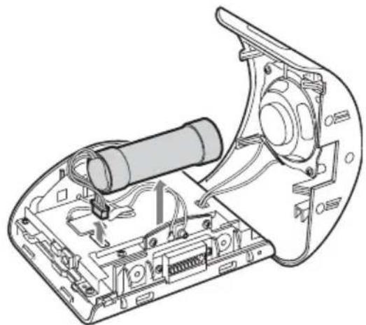
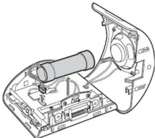
Remove the built-in lithium-ion battery when disposing of the unit, and return the battery to a recycling location.
The procedure for removing the battery is explained below.
Note
Never disassemble the unit except when disposing of it.
1 Switch off the main power by sliding the POWER switch to the OFF position.
2 Remove the jack cover (page 10).
3 Remove the 2 screws on the underside of the unit using a screwdriver.

natural_image
Line drawing of a device rear panel with connectors and ports (no text or symbols)4 Slide the rear cover, then lift to open.

5 Remove the battery.
natural_image
Technical line drawing of an electronic device with internal components and wiring (no text or symbols)6 Insulate the connector terminal by wrapping with a tape.
Notes on the lithium-ion battery
- Keep the battery out of the reach of children.
- Do not hold the battery with metallic tweezers, otherwise a short-circuit may occur.
WARNING
Battery may explode if mistreated. Do not recharge, disassemble, or dispose of in fire.
Specifications
Main unit
Operating temperature: 5 - 45 °C (41 - 113 °F)
Power requirements: DC 5 V (from supplied AC power adapter)
Connection terminals:
Cradle connector DC IN 5V jack USB jack External GPS antenna (aerial) jack
Speaker: 2-way speaker
Consumption current: Approx. 0.5 A
Dimensions: Approx. 104.7 × 87.5 × 42.9 mm (4.1 × 3.5 × 1.8 in) (w × h × d)
Mass: Approx. 310 g (11 oz)
Monitor
System: Transmissive liquid crystal display
Drive system: a-Si TFT active matrix system
Dimensions: 3.5 in (4:3) 70.1 × 52.6, 87.6 mm (2.8 × 2.1, 3.5 in) (h × v, d)
Segment: 230,400 (960 × 240) dots
Cradle
Operating temperature: 5 - 45 °C (41 - 113 °F)
Power requirements: DC 5.2 V (from supplied 12 V car battery adapter (negative earth))
Connection terminals:
Unit connector DC IN 5.2V jack TMC aerial jack (NV-U70T/U50T only)
Reception frequency: 87.5 - 108.0 MHz (NV-U70T/U50T only)
Optional accessories
External GPS Antenna: VCA-41
TMC Car Cradle Kit: NVA-CU3T
Car Cradle Kit: NVA-CU3
Car Install Kit: XA-49FM
European Map Package: NVD-DU3
(for NV-U50T/U50)
Design and specifications are subject to change without notice.

- Lead-free solder is used for soldering.
- Halogenated flame retardants are not used in the certain printed wiring boards.
- Use of rechargeable lithium ion batteries.
- Corrugated cardboard is used for the packaging cushions.
• VOC (Volatile Organic Compound)-free vegetable oil based ink is used for printing the carton. - This manual is printed on 100 % recycled paper using VOC (Volatile Organic Compound)-free vegetable oil based ink.
Troubleshooting
The following checklist will help you remedy problems you may encounter with your unit.
Before going through the checklist below, check the connection and operating procedures.
The operation icons on the display do not function.
An operation may take time while a map is displayed.
The unit does not turn on.
→Check that the POWER switch on the bottom right of the unit is in the ON position.
→Charge the built-in battery.
→Check that the unit is securely attached to the cradle (page 8).
The built-in battery cannot be charged.
→Check that the POWER switch on the bottom right of the unit is in the ON position.
→If the AC power adapter is being used, disconnect it from the outlet, then reconnect.
→The built-in lithium-ion battery can be charged at temperatures between 5 – 45 °C (41 – 113 °F). The battery may not be charged if the temperature inside the unit increases because of direct sunlight exposure, etc. This is not a malfunction.
GPS signal cannot be received.
- The system cannot receive GPS signals due to an obstruction.
→Move your car to a place where signals can be received clearly.
• GPS signal reception is low.
→Check the GPS information.
→The optional External GPS Antenna VCA-41 may be required for a heated or heat reflective windscreen. - There is an obstacle in front of the GPS aerial.
→Install the unit where the signal is not interrupted by the body of the car, etc. For details on the unit installation, see “Installing location” on page 5. - Signal may not be received if a window film is attached. In that case, use the optional External GPS Antenna VCA-41.
The car position on the map does not match the current road.
The error margin of the signal from the GPS satellites is too large. A maximum error margin of a few hundred metres can exist.
Voice guidance cannot be heard.
The volume is set too low.
→Raise the volume in the setting menu (page 16). When the unit is powered by the built-in battery, maximum available volume is 70 %, even if set higher (80 %, etc).
The LCD is not displayed normally.
- In high temperatures, the LCD may darken and not display clearly. In low temperatures, afterimage may occur on the LCD. These are not malfunctions, and the LCD will return to normal when the temperature returns to within the specified operating range.
- The LCD is dark, or the map colour has changed.
→The auto dimmer function may be activated because its sensor (page 10) is covered by a hand, etc.
Resetting the unit
If the navigation software freezes, try resetting the unit.
Press the RESET button with a pointed object, such as a ballpoint pen.
If the problem persists, switch off the main power by sliding the POWER switch to the OFF position, then switch on again after approximately 10 seconds.

Note
After you switch off the main power, it may take time to receive GPS signals when switching on again.
Wichtig!
natural_image
Line drawing of a rectangular electronic device with a power outlet labeled 'I/1' (no text or symbols on the device itself)natural_image
Line drawing of a rectangular electronic device with two ports and a screen (no text or symbols)natural_image
Line drawing of a mechanical device with gears and a base housing (no text or symbols)• Autobatterieadapter (1)

natural_image
Line drawing of a handheld electric shaver with coiled cable (no text or symbols)- Netzteil (1)
natural_image
Line drawing of a rectangular electronic device with attached cables (no text or symbols)- Netzkabel
- Beim NV-U70TW/U70TC*2 (2)

natural_image
Two types of electrical plug wires with metal fittings, no text or symbols visible- Beim NV-U50TG/U50G ^*2 (1)

- Beim NV-U50F/U50D/U50I/U50A/U50B/U50S/U50N*2 (1)

• USB-Kabel (1)

natural_image
Line drawing of a USB cable with two connectors (no text or symbols)natural_image
Line drawing of a coiled cable with two circular components, no text or symbols presentnatural_image
Simple line drawing of a folded paper or bag with visible stitching and straps (no text or symbols)natural_image
Line drawing of a mechanical device with a central hub and mounting base (no text or symbols)natural_image
Illustration showing two-step instructions for adjusting a mechanical component, with no visible text or symbols.natural_image
Technical illustration of a microscope and cable connector (no text or symbols)natural_image
Technical line drawing of a microscope with adjustment knobs and a slide (no text or symbols)natural_image
Line drawing of a hand holding a knife with a handle, showing no text or symbolsnatural_image
Line drawing of a handheld device with ports and connectors, no text or symbols presentnatural_image
Line drawing of a car steering wheel with a mounted sensor (no text or symbols)natural_image
Line drawing of a tablet device with a screen and two buttons, no text or symbols presentnatural_image
Line drawing of a cable inserted into a device with two connectors (no text or symbols)natural_image
Line drawing of a device rear panel with two screws inserted (no text or symbols)natural_image
Technical line drawing of an electronic device with internal components and wiring (no text or symbols)natural_image
Line drawing of a rectangular electronic device with a screen and two ports, no text or symbols present- Appareil principal (1)

natural_image
Line drawing of a rectangular electronic device with two mounting holes and a screen (no text or symbols)natural_image
Technical line drawing of a mechanical device with gears and housing (no text or symbols)natural_image
Line drawing of a handheld electric shaver with coiled cable (no text or symbols)natural_image
Line drawing of a rectangular electronic device with two ports and a coiled cable (no text or symbols)natural_image
Two types of electrical plug wires with metal fittings, no text or symbols visiblenatural_image
Line drawing of a USB cable with two connectors (no text or symbols)- Antenne TMC (1)/ventouses (2) (Pour le NV-U70T/U50T)

natural_image
Line drawing of a medical or electrical device with three circular components and a coiled cable (no text or symbols)- Ruban adhésif (1)

- Tampon (1)

- Etui de transport (1)

natural_image
Simple line drawing of a folded bag or pouch with straps and stitching (no text or symbols)natural_image
Line drawing of a mechanical device with a knob and lever mechanism (no text or symbols)natural_image
Illustration of a hand holding a circular device with an arrow indicating direction (no text or symbols)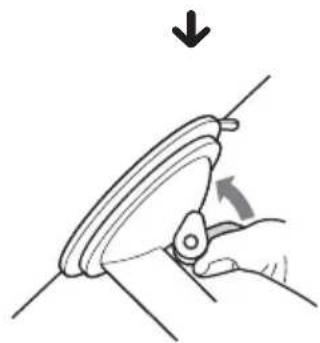
natural_image
Illustration of a hand holding a curved mechanical component with an arrow indicating rotation (no text or symbols)natural_image
Technical illustration of a mechanical device with a close-up view showing internal components (no text or symbols)natural_image
Technical line drawing of a microscope with adjustment arrows indicating mechanical components (no text or symbols)natural_image
Line drawing of a hand holding a flat tool with a dial indicator (no text or symbols present)natural_image
Line drawing of a vacuum cleaner device with attached cable and connector (no text or symbols)natural_image
Line drawing of a car steering wheel with a mounted sensor (no text or symbols)natural_image
Line drawing of a rectangular electronic device with a screen and two ports, no text or symbols presentnatural_image
Line drawing of a cable inserted into a device with two connectors (no text or symbols)natural_image
Line drawing of a device rear panel with connectors and ports (no text or symbols)5 Retirez la batterie.

natural_image
Technical line drawing of an electronic device showing internal components and wiring (no text or symbols)natural_image
Line drawing of a rectangular electronic device with a screen and two ports, connected by a power outlet (no text or symbols)natural_image
Line drawing of a rectangular electronic device with two mounting holes and a screen (no text or symbols)- Supporto*1 (1)
natural_image
Line drawing of a mechanical device with gears and a base (no text or symbols)natural_image
Line drawing of a handheld electric shaver with coiled cable (no text or symbols)natural_image
Line drawing of a rectangular electronic device with two ports and a coiled cable (no text or symbols)natural_image
Two types of electrical plug wires with metal fittings, no text or symbols visible- Per NV-U50TG/U50G*2 (1)

- Per NV-U50F/U50D/U50I/U50A/U50B/U50S/U50N*2 (1)
• Cavo USB (1)

natural_image
Line drawing of a USB cable with two connectors (no text or symbols)- Antenna TMC (1)/ventose (2) (per NV-U70T/U50T)

natural_image
Line drawing of a medical or electrical device with three circular components and a coiled cable (no text or symbols)natural_image
Simple line drawing of a folded bag or pouch with straps and stitching (no text or symbols)natural_image
Line drawing of a mechanical device with a knob and base mount (no text or symbols)natural_image
Illustration of a hand holding a device with an arrow indicating direction (no text or symbols)
natural_image
Illustration of a hand using a tool to lift a curved mechanical component, with an arrow indicating rotation (no text or symbols)natural_image
Technical illustration of a microscope with an inset showing cable connection (no text or symbols)natural_image
Technical line drawing of a microscope with adjustment arrows indicating mechanical components (no text or symbols)natural_image
Line drawing of a hand holding a knife with a triangular handle and a small circular component labeled 'B1500' (no text or symbols on the object itself)natural_image
Line drawing of a mechanical device with a lever and connector, showing internal components (no text or symbols)natural_image
Line drawing of a car with a mounted sensor and connecting rod (no text or symbols)Parte anteriore:

Parte posteriore:

natural_image
Line drawing of a rectangular electronic device with a screen and two ports, no text or symbols presentnatural_image
Line drawing of a cable inserted into a device with two connectors (no text or symbols)natural_image
Line drawing of a device rear panel with connectors and ports (no text or symbols)natural_image
Technical line drawing of an electronic device showing internal components and wiring (no text or symbols)natural_image
Line drawing of a rectangular electronic device with a screen and two ports, connected by a power outlet labeled 'I/1' (no text or symbols on the device itself)natural_image
Line drawing of a rectangular electronic device with two mounting holes and a screen (no text or symbols)- Houder ^*1 (1)

natural_image
Line drawing of a mechanical device with gears and a base (no text or symbols)- Accuadapter (1)

natural_image
Line drawing of a handheld electric shaver with coiled cable (no text or symbols)- Netspanningsadapter (1)
natural_image
Line drawing of a rectangular electronic device with cables and connectors (no text or symbols)natural_image
Two types of electrical plugs tied with coiled wires, no text or symbols visible- Voor NV-U50TG/U50G* (1)

- Voor NV-U50F/U50D/U50I/U50A/U50B/U50S/U50N*2 (1)
- USB-kabel (1)

natural_image
Line drawing of a USB cable with two connectors and a clip, no text or symbols present• TMC-antenne (1)/zuignappen (2) (Voor NV-U70T/U50T)
natural_image
Line drawing of a medical or electrical device with three circular components and a coiled cable (no text or symbols)- Plakstrip (1)
• Kussentje (1)

- Draagtas (1)
natural_image
Simple line drawing of a bag with straps and handles (no text or symbols)natural_image
Line drawing of a mechanical device with a circular head and lever mechanism (no text or symbols)natural_image
Illustration showing a hand holding a device with an arrow indicating rotation (no text or symbols present)natural_image
Technical illustration of a microscope with an inset showing a cable being inserted (no text or symbols present)natural_image
Technical line drawing of a microscope device with adjustment arrows indicating mechanical components (no text or symbols)natural_image
Line drawing of a hand holding a knife with a triangular handle and a circular arrow labeled 'ISO' (no text or symbols on the diagram itself)natural_image
Line drawing of a mechanical device with a lever and attached cable (no text or symbols)natural_image
Line drawing of a car steering wheel with a mounted sensor (no text or symbols)Voorkant:

Achterkant:

natural_image
Line drawing of a rectangular electronic device with a screen and two ports, no text or symbols presentnatural_image
Line drawing of a cable inserted into a device with two connectors (no text or symbols)natural_image
Line drawing of a device rear panel with screws inserted, showing internal components and mounting points (no text or symbols)natural_image
Technical line drawing of an electronic device with internal components and wiring (no text or symbols)natural_image
Line drawing of a rectangular electronic device with a screen and two ports, connected by a power outlet labeled 'I/1' (no text or symbols on the device itself)natural_image
Line drawing of a rectangular electronic device with two mounting holes and a screen (no text or symbols)- Base*1 (1)

natural_image
Line drawing of a mechanical device with gears and a base plate (no text or symbols)natural_image
Line drawing of a handheld electric shaver with coiled cable (no text or symbols)natural_image
Line drawing of a rectangular electronic device with attached cables (no text or symbols)natural_image
Two types of electrical plug wires with metal fittings, no text or symbols visible- Para NV-U50TG/U50G*2 (1)

- Para NV-U50F/U50D/U50I/U50A/U50B/U50S/U50N*2 (1)
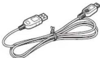
• Cable USB (1)
natural_image
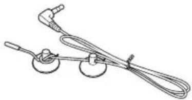
Illustration of two USB connectors tied with a coiled cable (no text or symbols)- Antena TMC (1)/ventosas (2) (Para NV-U70T/U50T)
natural_image
Line drawing of a medical or electrical device with three circular components and a coiled cable (no text or symbols)• Cinta adhesiva (1)

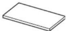
- Almohadilla (1)
• Funda de transporte (1)

natural_image
Simple line drawing of a folded bag or pouch with straps and a handle (no text or symbols)natural_image
Line drawing of a mechanical device with a knob and lever mechanism (no text or symbols)natural_image
Illustration showing a hand holding a device with an arrow indicating the process (no text or symbols present)natural_image
Technical illustration of a mechanical device with a close-up view showing internal components (no text or symbols)natural_image
Technical line drawing of a microscope with adjustment arrows indicating mechanical components (no text or symbols)natural_image
Line drawing of a hand holding a small electronic device with a button labeled 'USB' and 'CHS' (no text or symbols beyond labels)natural_image
Line drawing of a vacuum cleaner device with attached cable and connector (no text or symbols)natural_image
Line drawing of a vehicle with a steering wheel and attached sensor device on a road (no text or symbols)Parte delantera:

Parte trasera:
natural_image
Line drawing of a rectangular electronic device with a screen and two circular ports, no text or symbols present.natural_image
Line drawing of a cable inserted into a device with two connectors (no text or symbols)natural_image
Line drawing of a device rear panel with screw connectors and ports (no text or symbols)natural_image
Technical line drawing of an electronic device showing internal components and wiring (no text or symbols)natural_image
Line drawing of a rectangular electronic device with a screen and two ports, no text or symbols presentnatural_image
Line drawing of a rectangular electronic device with two mounting holes and a screen (no text or symbols)• F ä s t ^1 e( f ^* )

natural_image
Line drawing of a mechanical device with gears and a base plate (no text or symbols)natural_image
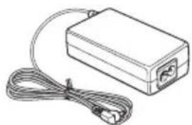
Line drawing of a handheld electric shaver with coiled cable (no text or symbols)- Nätadapter (1)
natural_image
Line drawing of a rectangular electronic device with two ports and a coiled cable (no text or symbols)natural_image
Two types of electrical plug wires with metal fittings, no text or symbols visiblenatural_image
Illustration of two USB connectors tied with coiled cables (no text or symbols)• TMC-antenn (luftantenn) (1)/sugkoppar (2) (För NV-U70T/U50T)

natural_image
Line drawing of a medical or electrical device with three circular components and wires (no text or symbols)• Dubbelhäftande tejp (1)

- Mellanlägg (1)
• Bärväska (1)

natural_image
Simple line drawing of a folded bag or pouch with straps and a handle (no text or symbols)natural_image
Line drawing of a mechanical device with a knob and lever mechanism (no text or symbols)natural_image
Illustration of a hand holding a device with an arrow indicating motion (no text or symbols)
natural_image
Illustration of a hand using a tool to lift a curved mechanical component, with an arrow indicating direction (no text or symbols)natural_image
Technical illustration of a mechanical device with a close-up view showing internal components (no text or symbols)natural_image
Technical line drawing of a microscope device with adjustment arrows indicating mechanical components (no text or symbols)natural_image
Line drawing of a hand holding a small electronic device with a button labeled 'USB' (no text or symbols on the device itself)natural_image
Line drawing of a vacuum cleaner's internal components with a cable inserted (no text or symbols)natural_image
Line drawing of a vehicle steering wheel with a mounted sensor and guide rails (no text or symbols)Framsida:

Baksida:
natural_image
Line drawing of a rectangular electronic device with a screen and two ports, no text or symbols present"Ny destination" → "Hem"
Intressanta Platser
Välj "Ny destination" → "Navigation" →
"Ny destination" → "Navigation" → "Favoriter"
Anvisningsskärmar
natural_image
Line drawing of a cable inserted into a device with two connectors (no text or symbols)natural_image
Line drawing of a device rear panel with connectors and ports (no text or symbols)5 Ta bort batteriet.

natural_image
Technical line drawing of an electronic device with internal components and wiring (no text or symbols)natural_image
Line drawing of a rectangular electronic device with a screen and two ports, no text or symbols presentnatural_image
Line drawing of a rectangular electronic device with two ports and a screen (no text or symbols)- Suporte*1 (1)

natural_image
Line drawing of a mechanical device with gears and a base plate (no text or symbols)natural_image
Line drawing of a handheld electric shaver with coiled cable (no text or symbols)- Transformador de CA (1)

natural_image
Line drawing of a rectangular electronic device with two ports and a coiled cable (no text or symbols)natural_image
Two types of electrical plugs tied with coiled wires, no text or symbols visible- NV-U50TG/U50G*2(1)

- NV-U50F/U50D/U50I/U50A/U50B/U50S/U50N*2 (1)

- Cabo USB (1)

natural_image
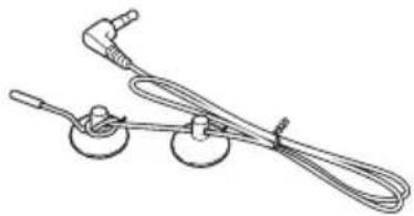
Coiled cable with two connectors and a connector pin (no text or symbols visible)- Antena TMC (1)/ventosas (2) (NV-U70T/U50T)
natural_image
Line drawing of a medical or electrical device with three circular components and a coiled cable (no text or symbols)- Fita adesiva (1)

- Almofada (1)
- Estojo de transporte (1)

natural_image
Simple line drawing of a folded bag or pouch with straps and a handle (no text or symbols)natural_image
Line drawing of a mechanical device with a curved base and lever (no text or symbols)natural_image
Illustration showing a hand holding a circular object with an arrow indicating rotation, before and after a change (no text or symbols present)natural_image
Technical illustration of a microscope with an inset showing a cable being inserted (no text or symbols present)natural_image
Technical line drawing of a microscope with adjustment knobs and a screen (no text or symbols)natural_image
Line drawing of a hand holding a small electronic device with a button labeled 'USB' and 'CHS Q' (no text or symbols beyond labels)natural_image
Line drawing of a vacuum cleaner with attached sensor and connector (no text or symbols)natural_image
Line drawing of a vehicle steering wheel with a mounted sensor and connecting rod (no text or symbols)Parte da frente:
Parte de trás:

natural_image
Line drawing of a rectangular electronic device with a screen and two ports, no text or symbols presentnatural_image
Line drawing of a cable inserted into a device with two connectors (no text or symbols)natural_image
Line drawing of a device rear panel with connectors and ports (no text or symbols)5 Retire a pilha.
natural_image
Technical line drawing of an electronic device showing internal components and wiring (no text or symbols)Nota
natural_image
Line drawing of a rectangular electronic device with a screen and two ports, no text or symbols presentnatural_image
Line drawing of a rectangular electronic device with two mounting holes and a screen (no text or symbols)natural_image
Line drawing of a mechanical device with gears and a base housing (no text or symbols)natural_image
Line drawing of a handheld electric shaver with coiled cable (no text or symbols)natural_image
Line drawing of a rectangular electronic device with two cables, no text or symbols presentnatural_image
Two types of electrical plug wires with black connectors, coiled in a row (no text or symbols visible)natural_image
Illustration of two USB connectors tied with a coiled cable (no text or symbols)natural_image
Line drawing of a coiled cable with two circular components, no text or symbols presentnatural_image
Simple line drawing of a folded bag or pouch with straps and a handle (no text or symbols)natural_image
Line drawing of a mechanical device with a central hub and mounting base (no text or symbols)natural_image
Illustration of a hand holding a circular device with an arrow indicating direction (no text or symbols)X
natural_image
Illustration of a hand holding a mechanical clamp or bracket, with an arrow indicating direction (no text or symbols present)natural_image
Technical illustration of a microscope with an inset showing a cable being inserted (no text or symbols present)natural_image
Technical line drawing of a microscope with adjustment knobs and a slide (no text or symbols)natural_image
Line drawing of a hand holding a knife with a button labeled 'B5.02' and 'CHG Q' (no text or symbols beyond labels)natural_image
Line drawing of a vacuum cleaner's internal components with a cable inserted (no text or symbols)natural_image
Line drawing of a car steering wheel with a mounted sensor (no text or symbols)natural_image
Line drawing of a rectangular electronic device with a screen and two ports, no text or symbols presentnatural_image
Line drawing of a cable inserted into a device with two connectors (no text or symbols)natural_image
Line drawing of a device rear panel with two screws inserted (no text or symbols)natural_image
Technical line drawing of an electronic device showing internal components and wiring (no text or symbols)natural_image
Line drawing of a rectangular electronic device with a screen and two ports, no text or symbols presentnatural_image
Line drawing of a rectangular electronic device with two mounting holes and a screen (no text or symbols)•Bàση* 1(1)

natural_image
Line drawing of a mechanical device with gears and a base plate (no text or symbols)natural_image
Line drawing of a handheld electric shaver with coiled cable (no text or symbols)natural_image
Line drawing of a rectangular electronic device with two ports and a coiled cable (no text or symbols)natural_image
Two types of electrical plugs tied with coiled wires, no text or symbols visiblenatural_image
Coiled cable with two connectors and a connector pin (no text or symbols visible)natural_image
Line drawing of a medical or electrical device with three circular components and wires (no text or symbols)natural_image
Simple line drawing of a folded bag or pouch with straps and a handle (no text or symbols)natural_image
Line drawing of a mechanical device with a knob and lever mechanism (no text or symbols)natural_image
Illustration of a hand holding a device with an arrow indicating direction (no text or symbols)
natural_image
Illustration of a hand using a tool to lift a curved mechanical component, with an arrow indicating direction (no text or symbols)natural_image
Technical illustration of a microscope and cable connector assembly (no text or symbols)natural_image
Technical line drawing of a microscope with adjustment arrows indicating mechanical components (no text or symbols)natural_image
Line drawing of a hand holding a small electronic device with a knob and adjustment knob (no text or symbols)natural_image
Line drawing of a handheld device with attached cable and connector (no text or symbols)natural_image
Line drawing of a car with a steering wheel and navigation device (no text or symbols)Εμπρός:

natural_image
Line drawing of a rectangular electronic device with a screen and two ports, no text or symbols presentnatural_image
Line drawing of a cable inserted into a device with two connectors (no text or symbols)Install PC connection software
Backup and Restore pre-installed map
natural_image
Line drawing of a device rear panel with connectors and ports (no text or symbols)natural_image
Technical line drawing of an electronic device showing internal components and wiring (no text or symbols)- Microsoft and Windows are registered trademarks of Microsoft Corporation.
- All other trademarks are trademarks of their respective owners.


V-Trafic Information in France is provided by Mediamobile company.

Traffic Information in the UK is provided by ITIS Holdings Plc.
© 1993 NAVTEQ. All Rights Reserved.
Ausw/Italy © 1994
Austria © 1996
Belgium © 1995
Benelux © 1993
Central Europe © 1993
Czech Republic © 2002
Denmark © 1997
Finland © 2001
France © 1993
Germany © 1993
Great Britain © 1993
Italy © 1994
Luxembourg © 1996
Mediterranean Coast © 1993
Norway © 2001
Portugal © 1997
Spain © 1997
Sweden © 1994
Switzerland © 1996
The Netherlands © 1993
Austria
Based on Ordnance Survey electronic data and used with the permission of the Controller of Her Majesty's Stationary Office © Crown Copyright, 1995.
Greece
© EuroGeographics; Copyright Geomatics Ltd.
Hungary
Copyright © 2003; Top-Map Ltd.
Italy
Copyright © 2000; Norwegian Mapping Authority
Portugal
Source: IgeoE – Portugal
Spain
Based upon electronic data © National Land Survey Sweden.
Switzerland
If you have any questions or for the latest support information on navigation, visit the website below:
http://www.sonydigital-link.com/navigation/


- Personal Navigation System
- Disposal of Old Electrical & Electronic Equipment (Applicable in the European Union and other European countries with separate collection systems)
- No guarantee for lost data or damaged data
- Caution
- Welcome!
- FEATURING:
- Table of Contents
- Getting Started 6
- Basic Operations 12
- Route Searching 13
- System Settings 16
- Using the Supplied Software 17
- Additional Information 18
- Important notice
- On handling
- On safety
- General
- Installation
- Installing location
- On GPS
- Note
- On the software
- Getting Started
- Checking the contents
- Installing the unit
- About the main power switch
- Notes
- About the suction mount
- Attach the cradle on the windscreen. Figure example of completed cradle installation
- If you want to fix the cradle on the windscreen permanently
- If the bottom of the cradle touches the dashboard
- Connect the cradle to the car cigarette lighter socket.
- Align the 2 slots on the underside of the unit with the tabs on the cradle, then push to snap the unit into place.
- Loosen the centre knob, fine adjust the angle so you can view the monitor properly, then retighten.
- Tip
- To detach the unit from the cradle
- Holding the unit, press the RELEASE button of the cradle.
- Take the unit out of the cradle.
- Installing the TMC aerial (NV-U70T/U50T only)
- Plug the TMC aerial cord into the TMC aerial jack on the left side of the cradle.
- Attach the end suction cup to the windscreen, then attach the other suction cup so as the cord forms 2 straight lines.
- Location of controls
- Front:
- Rear:
- VOICE/POSITION button
- 2Speaker
- Display window/touch screen
- I/⏻ (on/standby) button 11
- CHG (battery charge) indicator
- USB jack 17
- Auto dimmer sensor
- DC IN 5V jack
- POWER switch 7,20
- External GPS antenna (aerial)\* jack
- RESET button 20
- Cradle connector
- Turning the unit on
- To turn the unit off
- Starting up the navigation
- Receiving GPS signals
- Basic Operations
- Menu operations
- Show the top menu.
- Touch "Settings," then touch a desired item.
- Touch ▲/▼ to scroll the list, then touch a desired setting item.
- Make the desired setting.
- Keyboard operations
- Route Searching
- Setting the destination and starting guidance
- Input the address details.
- Select "Start navigation."
- Select "Start navigation" again.
- Setting the destination in other ways
- Search nearby
- Home
- Point of interest
- "---nearby"
- “---nationwide”
- “---in a town”
- Select on map
- Recent destinations
- Favourites
- Guidance displays
- 2D map display
- 3D map display
- View route display
- Map scrolling mode
- System Settings
- Volume
- Select map
- Map information
- Route information
- Signpost information
- Light sensor
- Graphical look
- Touch screen calibration
- Auto mode
- Routing options
- Itinerary
- Time zone
- Format
- Select language
- Home address
- Radio muting *2
- Demo mode
- Product information
- Using the Supplied Software
- Operating system requirements
- Connecting to your computer
- Notes when transferring data
- Software features
- Install PC connection software
- Backup and Restore pre-installed map (NV-U50T/U50 only)
- Map Manager
- Language Manager
- Read the manual
- Support link
- Re-install application
- Additional Information
- Precautions
- Moisture condensation
- Note on LCD panel
- Maintenance
- Fuse replacement
- Warning
- Notes on unit disposal
- Notes on the lithium-ion battery
- Specifications
- Main unit
- Monitor
- Cradle
- Optional accessories
- Troubleshooting
- The operation icons on the display do not function.
- The unit does not turn on.
- The built-in battery cannot be charged.
- GPS signal cannot be received.
- The car position on the map does not match the current road.
- Voice guidance cannot be heard.
- The LCD is not displayed normally.
- Resetting the unit
- Wichtig!
- Voorkant:
- Achterkant:
- Framsida:
- Baksida:
- Intressanta Platser
- Anvisningsskärmar
- Nota
- Εμπρός:
- Backup and Restore pre-installed map
- Austria
- Greece
- Hungary
- Italy
- Portugal
- Spain
- Switzerland
Brand : SONY
Model : NV-U70T
Category : GPS Navigator