HR4011C - Drill MAKITA - Free user manual and instructions
Find the device manual for free HR4011C MAKITA in PDF.

User questions about HR4011C MAKITA
0 question about this device. Answer the ones you know or ask your own.
Ask a new question about this device
Download the instructions for your Drill in PDF format for free! Find your manual HR4011C - MAKITA and take your electronic device back in hand. On this page are published all the documents necessary for the use of your device. HR4011C by MAKITA.
USER MANUAL HR4011C MAKITA
natural_image
Line drawing of a Maktor drill press with no visible text or symbols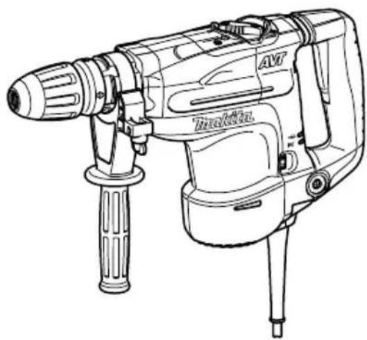
natural_image
Line drawing of a traditional electric drill with a torque selector and handle (no text or symbols)

text_image
ON I 11
text_image
OFF 2 ON ON 12

text_image
33
text_image
HR4001C HR4010C 5 4 64

text_image
HR4011C 5 4 65

text_image
HR4001C HR4010C 6 5 46
text_image
HR4001C HR4010C 5 6 47
text_image
HR4011C 6 5 48

text_image
7 89
natural_image
Pure technical line drawings of mechanical components without any text or symbols10
text_image
9 1011 12
text_image
11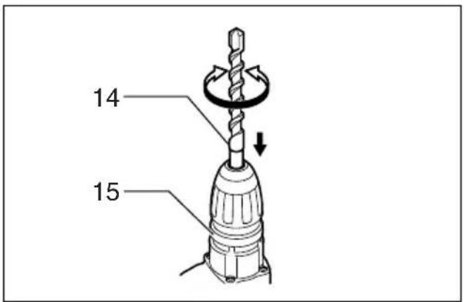
text_image
14 15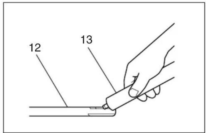
text_image
12 1313 14

text_image
14 1515 16

text_image
HR4001C HR4010C 6 5 4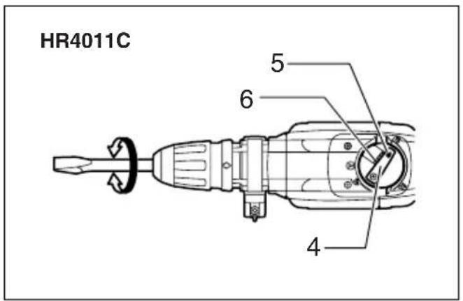
text_image
HR4011C 5 6 4
text_image
HR4001C HR4010C 5 6 417 18
text_image
HR4011C 5 6 4
text_image
16 1719 20
natural_image
Line drawing of a hand holding a drill bit with a tool, positioned in a 3D coordinate system (no text or symbols)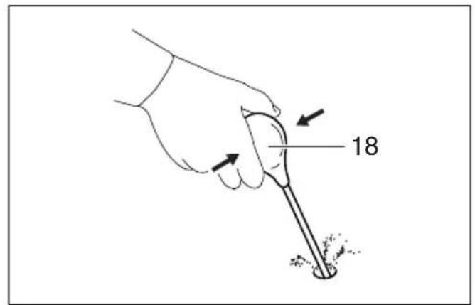
text_image
1821 22
natural_image
Line drawing of a hand using a drill bit to trigger an electric shock wave (no text or symbols)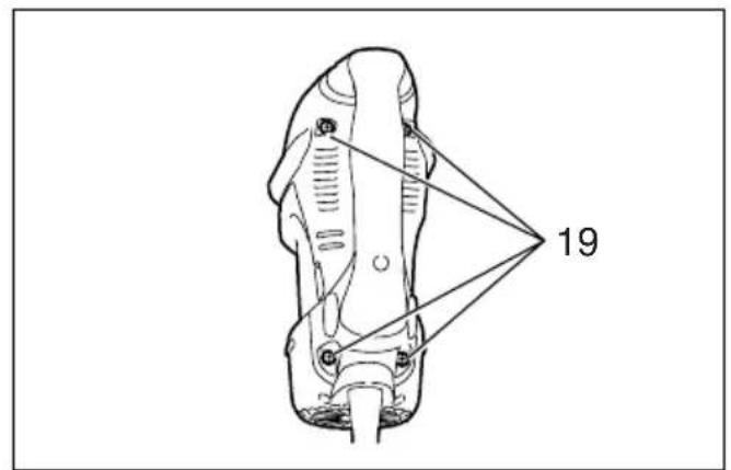
text_image
1923 24

text_image
20 21 22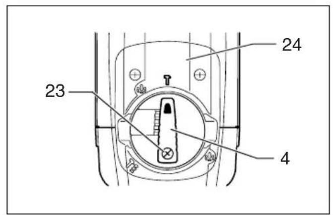
text_image
23 24 425 26
text_image
25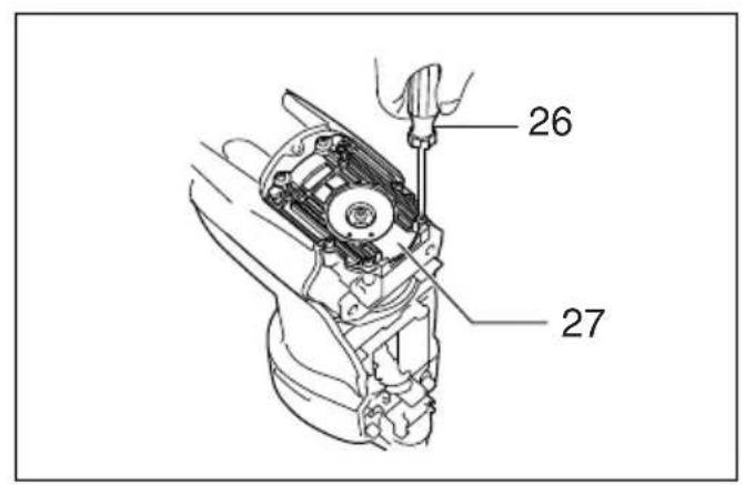
text_image
26 2727 28

text_image
28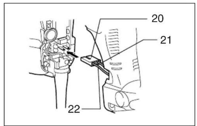
text_image
20 21 2229 30
ENGLISH
| Explanation of general view | ||
| 1 Switch trigger | 10 Clamp nut | 20 Connector |
| 2 Switch lever | 11 Side grip | 21 Black |
| 3 Adjusting dial | 12 Bit shank | 22 White |
| 4 Change lever | 13 Bit grease | 23 Screw |
| 5 Pointer | 14 Bit | 24 Crank cap cover |
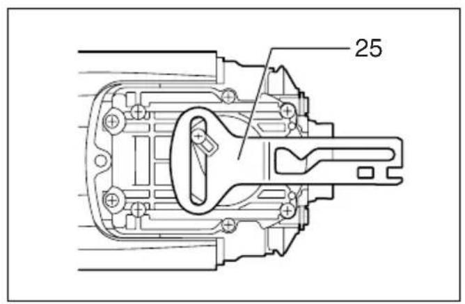
| 6 Lock button | 15 Chuck cover | 25 Control plate |
| 7 Power-ON indicator lamp (green) | 16 Depth gauge | 26 Screwdriver |
| 17 Clamp screw | 27 Crank cap | |
| 8 Service indicator lamp (red) | 18 Blow-out bulb | 28 Hammer grease |
| 9 Side handle | 19 Screws | |
SPECIFICATIONS
| Model HR4001C HR4010C HR4011C | |||
| Capacities | Carbide-tipped bit 40 mm | ||
| Core bit 105 mm | |||
| No load speed (min ^-1 ) 235 – 480 | |||
| Blows per minute | 1,350 – 2,750 | ||
| Overall length | 468 mm | ||
| Net weight | 6.3 kg | 6.7 kg | |
| Safety class | ☐/II | ||
- Due to our continuing program of research and development, the specifications herein are subject to change without notice.
- Specifications may differ from country to country.
• Weight according to EPTA-Procedure 01/2003
Intended use
The tool is intended for hammer drilling in brick, concrete and stone as well as for chiselling work.
Power supply
The tool should be connected only to a power supply of the same voltage as indicated on the nameplate, and can only be operated on single-phase AC supply. They are double-insulated in accordance with European Standard and can, therefore, also be used from sockets without earth wire.
Safety hints
For your own safety, please refer to the enclosed safety instructions.
SPECIFIC SAFETY RULES
GEB007-5
DO NOT let comfort or familiarity with product (gained from repeated use) replace strict adherence to rotary hammer safety rules. If you use this tool unsafely or incorrectly, you can suffer serious personal injury.
- Wear ear protectors. Exposure to noise can cause hearing loss.
-
Use auxiliary handle(s), if supplied with the tool. Loss of control can cause personal injury.
-
Hold power tools by insulated gripping surfaces, when performing an operation where the cutting accessory may contact hidden wiring or its own cord. Cutting accessory contacting a "live" wire may make exposed metal parts of the power tool "live" and could give the operator an electric shock.
- Wear a hard hat (safety helmet), safety glasses and/or face shield. Ordinary eye or sun glasses are NOT safety glasses. It is also highly recommended that you wear a dust mask and thickly padded gloves.
- Be sure the bit is secured in place before operation.
- Under normal operation, the tool is designed to produce vibration. The screws can come loose easily, causing a breakdown or accident. Check tightness of screws carefully before operation.
- In cold weather or when the tool has not been used for a long time, let the tool warm up for a while by operating it under no load. This will loosen up the lubrication. Without proper warm-up, hammering operation is difficult.
- Always be sure you have a firm footing. Be sure no one is below when using the tool in high locations.
- Hold the tool firmly with both hands.
- Keep hands away from moving parts.
- Do not leave the tool running. Operate the tool only when hand-held.
- Do not point the tool at any one in the area when operating. The bit could fly out and injure someone seriously.
-
Do not touch the bit or parts close to the bit immediately after operation; they may be extremely hot and could burn your skin.
-
Some material contains chemicals which may be toxic. Take caution to prevent dust inhalation and skin contact. Follow material supplier safety data.
SAVE THESE INSTRUCTIONS.
WARNING:
MISUSE or failure to follow the safety rules stated in this instruction manual may cause serious personal injury.
FUNCTIONAL DESCRIPTION
CAUTION:
- Always be sure that the tool is switched off and unplugged before adjusting or checking function on the tool.
Switch action
FOR MODEL HR4011C
CAUTION:
- Before plugging in the tool, always check to see that the switch trigger actuates properly and returns to the "OFF" position when released.
To start the tool, simply pull the switch trigger. Release the switch trigger to stop. (Fig. 1)
FOR MODELS HR4010C AND HR4001C
Trigger switch
CAUTION:
- Before plugging in the tool, always check to see that the switch trigger actuates properly and returns to the "OFF" position when released.
- This switch functions when setting the tool in symbol and symbol modes.
To start the tool, simply pull the switch trigger. Release the switch trigger to stop. (Fig. 1)
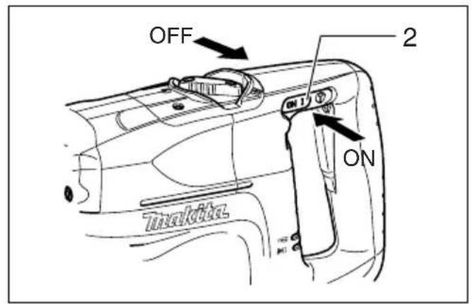
Slide switch
CAUTION:
- Before plugging in the tool, always check to see that the tool is switched off.
- This switch functions only when setting the tool in symbol action mode.
When using the tool in the hammering mode for a long time, the slide switch is available. To start the tool, push the "I (ON)" side of the switch lever. To stop the tool, push the "O (OFF)" side of the switch lever. (Fig. 2)
Speed change (Fig. 3)
The revolutions and blows per minute can be adjusted just by turning the adjusting dial. The dial is marked 1 (lowest speed) to 5 (full speed).
Refer to the table below for the relationship between the number settings on the adjusting dial and the revolutions/blows per minute.
| Number on adjusting dial | Revolutions per minute | Blows per minute |
| 5 480 2,750 | ||
| 4 440 2,550 | ||
| 3 360 2,050 | ||
| 2 270 1,550 | ||
| 1 230 1,350 |
CAUTION:
- If the tool is operated continuously at low speeds for a long time, the motor will get overloaded, resulting in tool malfunction.
- The speed adjusting dial can be turned only as far as 5 and back to 1. Do not force it past 5 or 1, or the speed adjusting function may no longer work.
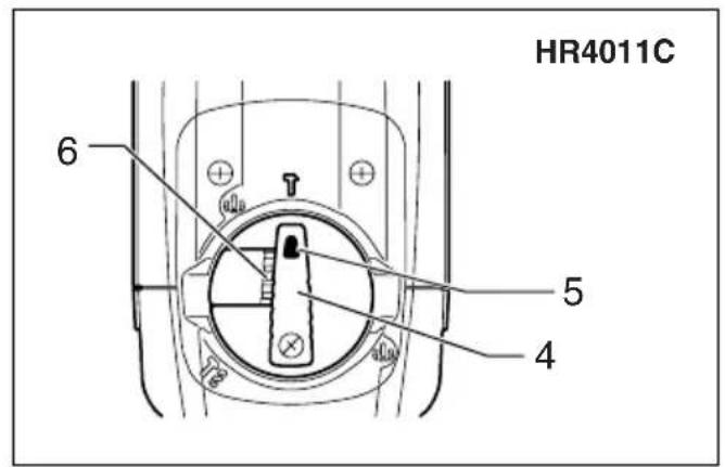
Selecting the action mode
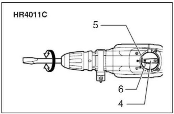
Rotation with hammering (Fig. 4 & 5)
For drilling in concrete, masonry, etc., depress the lock button and rotate the change lever so that the pointer points to the symbol. Use a tungsten-carbide tipped bit.
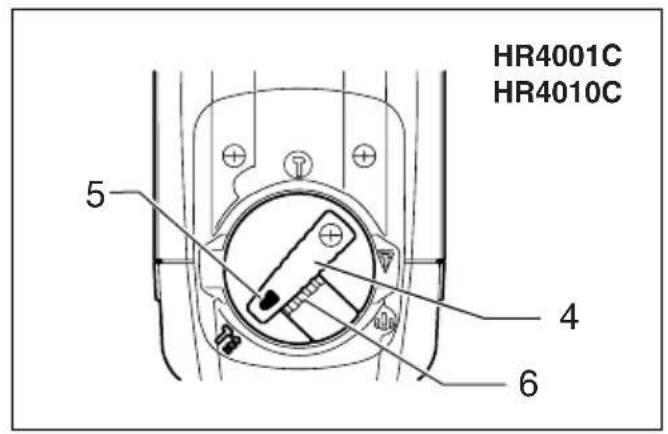
Hammering only
FOR MODELS HR4001C AND HR4010C (Fig. 6)
For chipping, scaling or demolition operations, depress the lock button and rotate the change lever so that the pointer points to the symbol. Use a bull point, cold chisel, scaling chisel, etc.
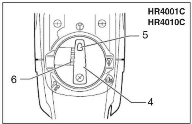
For long time hammering (FOR MODELS HR4001C AND HR4010C ONLY) (Fig. 7)
For chipping, scaling or demolition operations, depress the lock button and rotate the change lever so that the pointer points to the symbol. Use a bull point, cold chisel, scaling chisel, etc.
CAUTION:
- When using the tool in the symbol mode, the switch trigger does not work and only the slide switch works.
FOR MODEL HR4011C (Fig. 8)
For chipping, scaling or demolition operations, depress the lock button and rotate the change lever so that the pointer points to the symbol. Use a bull point, cold chisel, scaling chisel, etc.
CAUTION:
- Do not rotate the change lever when the tool is running under load. The tool will be damaged.
- To avoid rapid wear on the mode change mechanism, be sure that the change lever is always positively located in one of the two or three action mode positions.
Torque limiter
The torque limiter will actuate when a certain torque level is reached. The motor will disengage from the output shaft. When this happens, the bit will stop turning.
CAUTION:
- As soon as the torque limiter actuates, switch off the tool immediately. This will help prevent premature wear of the tool.
Indicator lamp (Fig. 9)
The green power-ON indicator lamp lights up when the tool is plugged. If the indicator lamp does not light up, the mains cord or the controller may be defective. The indicator lamp is lit but the tool does not start even if the tool is switched on, the carbon brushes may be worn out, or the controller, the motor or the ON/OFF switch may be defective.
The red service indicator lamp lights up when the carbon brushes are nearly worn out to indicate that the tool needs servicing. After approx. 8 hours of use, the motor will automatically be shut off.
ASSEMBLY
CAUTION:
- Always be sure that the tool is switched off and unplugged before carrying out any work on the tool.
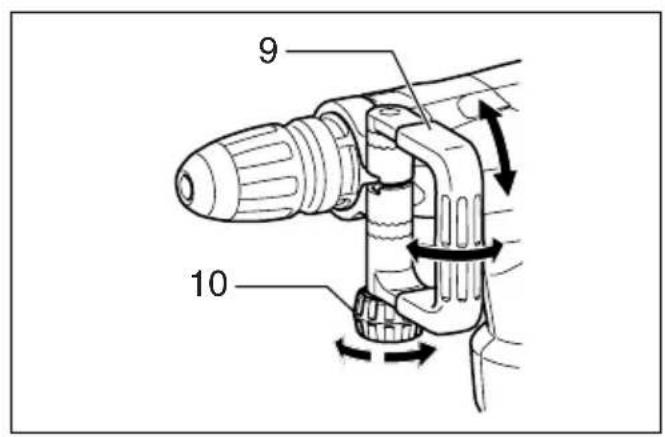
Side handle
CAUTION:
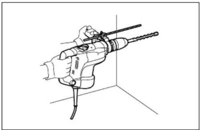
- Use the side handle only when chipping, scaling or demolishing. Do not use it when drilling in concrete, masonry, etc. The tool cannot be held properly with this side handle when drilling. (Fig. 10)
The side handle can be swung 360^ on the vertical and secured at any desired position. It also secures at eight different positions back and forth on the horizontal. Just loosen the clamp nut to swing the side handle to a desired position. Then tighten the clamp nut securely. (Fig. 11)
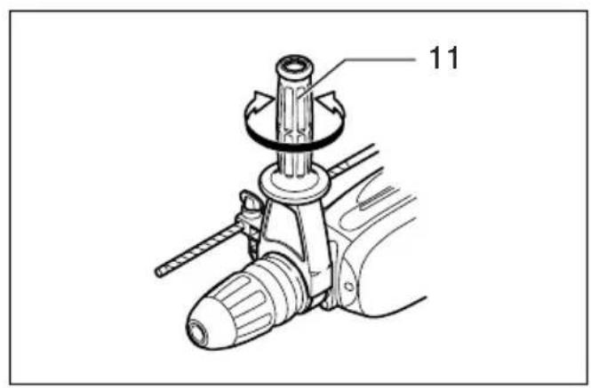
Side grip (Fig. 12)
CAUTION:
- Always use the side grip to ensure operating safety when drilling in concrete, masonry, etc.
The side grip swings around to either side, allowing easy handling of the tool in any position. Loosen the side grip by turning it counterclockwise, swing it to the desired position and then tighten it by turning clockwise.
Installing or removing the bit
Clean the bit shank and apply bit grease before installing the bit. (Fig. 13)
Insert the bit into the tool. Turn the bit and push it in until it engages.
If the bit cannot be pushed in, remove the bit. Pull the chuck cover down a couple of times. Then insert the bit again. Turn the bit and push it in until it engages.
After installing, always make sure that the bit is securely held in place by trying to pull it out. (Fig. 14)
To remove the bit, pull the chuck cover down all the way and pull the bit out. (Fig. 15)
Bit angle (when chipping, scaling or demolishing)
The bit can be secured at 12 different angles. To change the bit angle, depress the lock button and rotate the change lever so that the pointer points to the symbol.
Turn the bit to the desired angle. (Fig. 16 & 17)
Depress the lock button and rotate the change lever so that the pointer points to the symbol. Then make sure that the bit is securely held in place by turning it slightly. (Fig. 18 & 19)
Depth gauge (Fig. 20)
The depth gauge is convenient for drilling holes of uniform depth. Loosen the clamp screw and adjust the depth gauge to the desired depth. After adjusting, tighten the clamp screw firmly.
NOTE:
- The depth gauge cannot be used at the position where the depth gauge strikes against the gear housing/motor housing.
OPERATION
Hammer drilling operation (Fig. 21)
Set the change lever to the symbol.
Position the bit at the desired location for the hole, then pull the switch trigger. Do not force the tool. Light pressure gives best results. Keep the tool in position and prevent it from slipping away from the hole.
Do not apply more pressure when the hole becomes clogged with chips or particles. Instead, run the tool at an idle, then remove the bit partially from the hole. By repeating this several times, the hole will be cleaned out and normal drilling may be resumed.
CAUTION:
- When the bit begins to break through concrete or if the bit strikes reinforcing rods embedded in concrete, the tool may react dangerously. Maintain good balance and safe footing while holding the tool firmly with both hands to prevent dangerous reaction.
Blow-out bulb (optional accessory) (Fig. 22)
After drilling the hole, use the blow-out bulb to clean the dust out of the hole.
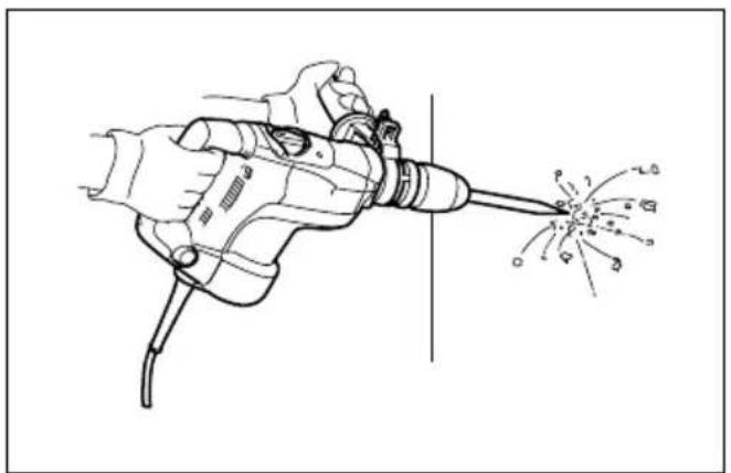
Chipping/Scaling/Demolition (Fig. 23)
Set the change lever to the symbol.
Hold the tool firmly with both hands. Turn the tool on and apply slight pressure on the tool so that the tool will not bounce around, uncontrolled. Pressing very hard on the tool will not increase the efficiency.
MAINTENANCE
CAUTION:
- Always be sure that the tool is switched off and unplugged before attempting to perform inspection or maintenance.
Lubrication
CAUTION:
- This servicing should be performed by Makita Authorized or Factory Service Centers only.
This tool requires no hourly or daily lubrication because it has a grease-packed lubrication system. Lubricate the tool every time the carbon brushes are replaced.
Run the tool for several minutes to warm it up. Switch off and unplug the tool.
Loosen the four screws and remove the handle. Note that the top screws are different from other screws. (Fig. 24)
Disconnect the connector by pulling them. (Fig. 25)
Loosen the screws and remove the change lever.
Remove the crank cap cover. (Fig. 26)
Remove the control plate. (Except for model HR4011C.) (Fig. 27)
Loosen the six screws with a screwdriver and remove the crank cap. Rest the tool on the table with the bit end pointing upwards. This will allow the old grease to collect inside the crank housing. (Fig. 28)
Wipe out the old grease inside and replace with a fresh grease (60 g). Use only Makita genuine hammer grease (optional accessory). Filling with more than the specified amount of grease (approx. 60 g) can cause faulty hammering action or tool failure. Fill only with the specified amount of grease.
Reinstall the crank cap and tighten with the screwdriver. (Fig. 29)
Connect the connector and reinstall the handle. (Fig. 30)
CAUTION:
- Do not tighten the crank cap excessively. It is made of resin and is subject to breakage.
- Be careful not to damage the connector or lead wires especially when wiping out the old grease or installing the handle.
To maintain product SAFETY and RELIABILITY, repairs, any other maintenance or adjustment should be performed by Makita Authorized Service Centers, always using Makita replacement parts.
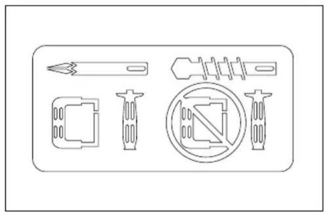
ACCESSORIES
CAUTION:
- These accessories or attachments are recommended for use with your Makita tool specified in this manual. The use of any other accessories or attachments might present a risk of injury to persons. Only use accessory or attachment for its stated purpose.
If you need any assistance for more details regarding these accessories, ask your local Makita service center.
• SDS-MAX Carbide tipped bit
- SDS-MAX bull point
- SDS-MAX cold chisel
• SDS-MAX scaling chisel
- SDS-MAX tile chisel
- SDS-MAX clay spade
- Hammer grease
- Bit grease
- Side handle
- Side grip
- Depth gauge
- Blow-out bulb
- Safety goggle
- Carrying case
Descriptif
EC Declaration of Conformity
We Makita Corporation as the responsible manufacturer declare that the following Makita machine(s):
Designation of Machine: Rotary Hammer
Model No./ Type: HR4001C, HR4010C, HR4011C
are of series production and
Conforms to the following European Directives:
98/37/EC until 28th December 2009 and then with 2006/42/EC from 29th December 2009
And are manufactured in accordance with the following standards or standardised documents:
EN60745
The technical documentation is kept by our authorized representative in Europe who is:
Makita International Europe Ltd,
Michigan, Drive, Tongwell,
Milton Keynes, MK15 8JD, England
FRANÇAISE
Makita International Europe Ltd, Michigan, Drive, Tongwell,
Milton Keynes, MK15 8JD, Angleterre
DEUTSCH
Michigan, Drive, Tongwell,
Milton Keynes, MK15 8JD, England
ITALIANO
Michigan, Drive, Tongwell,
Milton Keynes, MK15 8JD, England
30th January 2009 30. Januar 2009
3-11-8, Sumiyoshi-cho,
Anjo, Aichi, JAPAN
NEDERLANDS
Michigan, Drive, Tongwell,
Milton Keynes, MK15 8JD, Engeland
ESPAÑOL
Michigan, Drive, Tongwell,
Milton Keynes, MK15 8JD, Inglaterra
PORTUGUÊS
Michigan Drive, Tongwell,
Milton Keynes, MK15 8JD, Inglaterra
DANSK
Michigan, Drive, Tongwell,
Milton Keynes, MK15 8JD, England
30 januari 2009 30 de janeiro de 2009
30 de enero de 2009 30. januar 2009

Tomoyasu Kato
Directeur Director
Director Direktør
Makita Corporation
3-11-8, Sumiyoshi-cho,
Anjo, Aichi, JAPAN
ΕΛΛΗΝΙΚΑ
Michigan, Drive, Tongwell,
Milton Keynes, MK15 8JD, England (Aγγλία)
30 lavouapiou 2009
Tomoyasu Kato
Διευθυντής
Makita Corporation
3-11-8, Sumiyoshi-cho,
Anjo, Aichi, JAPAN
ENGLISH
For Model HR4001C
ENG102-2
For European countries only
Noise
The typical A-weighted noise level determined according to EN60745:
Sound pressure level ( L_pA ): 92 dB (A)
Sound power level ( L_WA ): 103 dB (A)
Uncertainty (K): 3 dB (A)
Wear ear protection.
ENG216-1
Vibration
The vibration total value (tri-axial vector sum) determined according to EN60745-2-6:
Work mode: chiseling function with side handle
Vibration emission (a _h, CHeq ): 10.5 m/s ^2
Uncertainty (K): 2.0 m/s ^2
ENG306-1
Work mode: chiseling function with side grip
Vibration emission ( _n, CHeq ): 10.0 m/s ^2
Uncertainty (K): 2.5 m/s²
ENG303-2
Work mode: hammer drilling into concrete
Vibration emission ( a_n, HD ): 12.5 m/s ^2
Uncertainty (K): 1.5 m/s ^2
FRANÇAISE
Incertezza (K): 2,0 m/s²
ENG306-1
For European countries only
Noise
The typical A-weighted noise level determined according to EN60745:
Sound pressure level ( L_pA ): 90 dB (A)
Sound power level ( L_WA ): 101 dB (A)
Uncertainty (K): 3 dB (A)
Wear ear protection.
ENG216-1
Vibration
The vibration total value (tri-axial vector sum) determined according to EN60745-2-6:
Work mode: chiseling function with side handle
Vibration emission ( a_h, CHeq ): 7.0 m/s ^2
Uncertainty (K): 1.5 m/s²
ENG306-1
Work mode: chiseling function with side grip
Vibration emission ( _h, CHeq ): 8.0 m/s ^2
Uncertainty (K): 1.5 m/s²
ENG303-2
Work mode: hammer drilling into concrete
Vibration emission ( a_h, HD ): 9.0 m/s ^2
Uncertainty (K): 1.5 m/s²
FRANÇAISE
Vibrationsemission ( a_h, CHeq ): 7,0 m/s ^2
Vibrationsemission ( a_h, CHeq ): 8,0 m/s ^2
Vibrationsemission ( _h, HD ): 9,0 m/s ^2
Vibrationsafgivelse (a _h, HD ): 9,0 m/s ^2
For European countries only
Noise
The typical A-weighted noise level determined according to EN60745:
Sound pressure level ( L_pA ): 90 dB (A)
Sound power level ( L_WA ): 101 dB (A)
Uncertainty (K): 3 dB (A)
Wear ear protection.
ENG216-1
Vibration
The vibration total value (tri-axial vector sum) determined according to EN60745-2-6:
Work mode: chiseling function with side handle
Vibration emission (a _n, CHeq ): 6.5 m/s ^2
Uncertainty (K): 1.5 m/s ^2
ENG306-1
Work mode: chiseling function with side grip
Vibration emission ( _n, CHeq ): 6.5 m/s ^2
Uncertainty (K): 1.5 m/s²
ENG303-2
Work mode: hammer drilling into concrete
Vibration emission (a _h, HD ): 7.5 m/s ^2
Uncertainty (K): 1.5 m/s ^2