USER MANUAL PDA-V100HD PIONEER
Operating Instructions I Mode d'emploi I Bedienungsanleitung I Istruzioni per I'uso I Handleiding I Manual de instrucciones I Иструкции по зации
HOMI
HIGH-DEFINITION MULTIMEDIA INTERFACE

ME20
HD AV Converter
Convertisseur HD
HD AV Converter
Convertore AV HD
HD AV converter
Conversor AV HD
HD AV KoHBepTep
PDA-V 100HD
Replacement and mounting of an AC plug on the power supply cord of this unit should be performed only by qualified service personnel.
IMPORTANT: THE MOULDED PLUG
This appliance is supplied with a moulded three pin mains plug for your safety and convenience. A 13 amp fuse is fitted in this plug. Should the fuse need to be replaced, please ensure that the replacement fuse has a rating of 13 amps and that it is approved by ASTA or BSI to BS1362.
Check for the ASTA mark or the BSI mark on the body of the fuse.
If the plug contains a removable fuse cover, you must ensure that it is refitted when the fuse is replaced. If you lose the fuse cover the plug must not be used until a replacement cover is obtained. A replacement fuse cover can be obtained from your local dealer.
If the fitted moulded plug is unsuitable for your socket outlet, then the fuse shall be removed and the plug cut off and disposed of safely. There is a danger of severe electrical shock if the cut off plug is inserted into any 13 amp socket.
If a new plug is to be fitted, please observe the wiring code as shown below. If in any doubt, please consult a qualified electrician.
WARNING : THIS APPARATUS MUST BE EARTHED.
IMPORTANT: The wires in this mains lead are coloured in accordance with the following code:
Green & Yellow : Earth Blue : Neutral Brown : Live
As the colours of the wires in the mains lead of this appliance may not correspond with the coloured markings identifying the terminals in your plug, proceed as follows ;
The wire which is coloured GREEN-AND-YELLOW must be connected to the terminal in the plug which is marked with the letter E or
by the earth symbol 12 or coloured GREEN or GREEN-AND-YELLOW.
The wire which is coloured BLUE must be connected to the terminal which is marked with the letter N or coloured BLACK.
The wire which is coloured BROWN must be connected to the terminal which is marked with the letter L or coloured RED.
How to replace the fuse: Open the fuse compartment with a screwdriver and replace the fuse.
D3-4-2-1-2-1_B_En
IMPORTANT

The lightning flash with arrowhead symbol, within an equilateral triangle, is intended to alert the user to the presence of uninsulated "dangerous voltage" within the product's enclosure that may be of sufficient magnitude to constitute a risk of electric shock to persons.
CAUTION
RISK OF ELECTRIC SHOCK DO NOT OPEN
CAUTION:
TO PREVENT THE RISK OF ELECTRIC SHOCK,DO NOT REMOVE COVER (OR BACK).NO USER-SERVICEABLE PARTS INSIDE.REFER SERVICING TO QUALIFIED SERVICE PERSONNEL.

The exclamation point within an equilateral triangle is intended to alert the user to the presence of important operating and maintenance (servicing) instructions in the literature accompanying the appliance.
D3-4-2-1-1_En-A

If you want to dispose this product, do not mix it with general household waste. There is a separate collection system for used electronic products in accordance with legislation that requires proper treatment, recovery and recycling.
Private households in the member states of the EU, in Switzerland and Norway may return their used electronic products free of charge to designated collection facilities or to a retailer (if you purchase a similar new one).
For countries not mentioned above, please contact your local authorities for the correct method of disposal.
By doing so you will ensure that your disposed product undergoes the necessary treatment, recovery and recycling and thus prevent potential negative effects on the environment and human health.
K058_A_En
CAUTION
The STANDBY/ON switch on this unit will not completely shut off all power from the AC outlet.
Since the power cord serves as the main disconnect device for the unit, you will need to unplug it from the AC outlet to shut down all power. Therefore, make sure the unit has been installed so that the power cord can be easily unplugged from the AC outlet in case of an accident. To avoid fire hazard, the power cord should also be unplugged from the AC outlet when left unused for a long period of time (for example, when on vacation).
D3-4-2-2-2a_A_En
WARNING
This equipment is not waterproof. To prevent a fire or shock hazard, do not place any container filed with liquid near this equipment (such as a vase or flower pot) or expose it to dripping, splashing, rain or moisture. D3-4-2-1-3_A_En
This product complies with the Low Voltage Directive 2006/95/EC and EMC Directive 2004/108/EC.
WARNING
This product equipped with a three-wire grounding (earthed) plug - a plug that has a third (grounding) pin. This plug only fits a grounding-type power outlet. If you are unable to insert the plug into an outlet, contact a licensed electrician to replace the outlet with a properly grounded one. Do not defeat the safety purpose of the grounding plug.
D3-4-2-1-6_A_En
Operating Environment
Operating environment temperature and humidity:
+0 °C to +40 °C (+32 °F to +104 °F); less than 85 % RH (cooling vents not blocked)
Do not install this unit in a poorly ventilated area, or in locations exposed to high humidity or direct sunlight (or strong artificial light) D3-4-2-1-7c_A_En
The following symbols are found on labels attached to the product. They alert the operators and service personnel of this equipment to any potentially dangerous conditions.

WARNING
This symbol refers to a hazard or unsafe practice which can result in personal injury or property damage.

CAUTION
This symbol refers to a hazard or unsafe practice which can result in severe personal injury or death.
WARNING
To prevent a fire hazard, do not place any naked flame sources (such as a lighted candle) on the equipment. D3-4-2-1-7a
D3-4-2-1-7a_A_En
VENTILATION CAUTION
When installing this unit, make sure to leave space around the unit for ventilation to improve heat radiation. For the minimum space required, see page 12.
WARNING
Slots and openings in the cabinet are provided for ventilation to ensure reliable operation of the product, and to protect it from overheating. To prevent fire hazard, the openings should never be blocked or covered with items (such as newspapers, table-cloths, curtains) or by operating the equipment on thick carpet or a bed.
STANDBY: When placed into the standby mode, the main power flow is cut and the unit is no longer fully operational.
STANDBY Indicator: When the STANDBY indicator lights red, the unit is in the standby mode.
Power ON indicator: When the power ON indicator lights blue, the unit is in the power on mode.
Thank you for buying this Pioneer product.
Please read through these operating instructions so you will know how to operate your model properly. After you have finished reading the instructions, put them away in a safe place for future reference. In some countries of regions, the shape of the power plug and power outlet may sometimes differ from that shown in the explanatory drawings. However the method of connecting and operating the unit are the same.
Contents
01 Important user information. 5
02 Safety precautions 6
03 Features. 7
04 Supplied accessories. 8
05 Part names. 9
Front 9
Rear. 10
Remote control unit. 11
06 Preparation 12
Installing the unit. 12
Preparing the remote control unit 12
Operating range of the remote control unit 13
07 Using the unit 14
Connecting the unit to a Pioneer plasma television (see Chapter 8) 15
Connecting the unit to other televisions
(see Chapter 9) 15
08 Using the unit with a Pioneer plasma television 16
09 Using the unit with other televisions 17
10 Advanced functions 18
Connecting control cables. 18
Changing settings 19
11 Using with other components. 21
Connections to a television 21
Connections to input components 21
Using the HDMI input 22
Connections to a HDMI-supported component .....22
About HDMI 22
Connections to a component equipped with SCART connector. 23
Connections to a component with component connectors 23
12 Additional information 24
Troubleshooting 24
SCART pin assignments 26
Specifications 27
Operation of the unit's indicators 28
In order to obtain maximum enjoyment from this unit, please first read this information carefully.
Do not attach such items as labels and tape to the product.
This may result in the discolouration or scratch of the cabinet.
When not using the product for a long period of time
If you do not use the product for a long period of time, the functions of the product may be adversely affected. Switch on and run the product occasionally.
Condensation
Condensation may take place on the surface or inside of the product when the product is rapidly moved from a cold place to a warm place or just after a heater is switched on in winter morning, for example. When condensation takes place, do not switch on the product and wait until condensation disappears. Using the product with condensation may result in malfunction.
Cleaning the cabinet
When cleaning the cabinet of this product, gently wipe it with a clean soft cloth (e.g., cotton and flannel). If you use a dusty or hard cloth or if you rub the cabinet hard, the surface of the cabinet will be scratched.
The cabinet of this product is mostly composed of plastic. Do not use chemicals such as benzene or thinner to clean the cabinet. Using these chemicals may result in quality deterioration or coating removal.
Do not expose the product to volatile gas or fluid such as pesticide. Do not make the product contact with rubber or vinyl products for a long period of time. The effect of plasticizer in the plastic may result in quality deterioration or coating removal.
If you clean the surface of the cabinet with a wet cloth, water droplets on the surface may enter into the product, resulting in malfunction.
Chapter 2
Safety precautions
Electricity is used to perform many useful functions, but it can also cause personal injuries and property damage if improperly handled. This product has been engineered and manufactured with the highest priority on safety. However, improper use can result in electric shock and/or fire. In order to prevent potential danger, please observe the following instructions when installing, operating and cleaning the product. To ensure your safety and prolong the service life of your product, please read the following precautions carefully before using the product.
- Read instructions - All operating instructions must be read and understood before the product is operated.
- Keep this manual in a safe place - These safety and operating instructions must be kept in a safe place for future reference.
- Observe warnings - All warnings on the product and in the instructions must be observed closely.
- Follow instructions - All operating instructions must be followed.
- Cleaning - Unplug the power cord from the AC outlet before cleaning the product. To clean the product, use the supplied cleaning cloth or other soft clothes (e.g., cotton, flannel). Do not use liquid cleaners or aerosol cleaners.
- Attachments - Do not use attachments not recommended by the manufacturer. Use of inadequate attachments can result in accidents.
- Water and moisture - Do not use the product near water, such as bathtub, washbasin, kitchen sink and laundry tub, swimming pool and in a wet basement.
- Stand - Do not place the product on an unstable cart, stand, tripod or table. Placing the product on an unstable base can cause the product to fall, resulting in serious personal injuries as well as damage to the product. Use only a cart, stand, tripod, bracket or table recommended by the manufacturer or sold with the product. When mounting the product on a wall, be sure to follow the manufacturer's instructions. Use only the mounting hardware recommended by the manufacturer.
- When relocating the product placed on a cart, it must be moved with utmost care. Sudden stops, excessive force and uneven floor surface can cause the product to fall from the cart.

-
Ventilation - The vents and other openings in the cabinet are designed for ventilation. Do not cover or block these vents and openings since insufficient ventilation can cause overheating and/or shorten the life of the product. Do not place the product on a bed, sofa, rug or other similar surface, since they can block ventilation openings. This product is not designed for built-in installation; do not place the product in an enclosed place such as a bookcase or rack, unless proper ventilation is provided or the manufacturer's instructions are followed.
-
Power source - This product must operate on a power source specified on the specification label. If you are not sure of the type of power supply used in your home, consult your dealer or local power company.
- Power cord protection - The power cords must be routed properly to prevent people from stepping on them or objects from resting on them. Check the cords at the plugs and product.
- Overloading - Do not overload AC outlets or extension cords. Overloading can cause fire or electric shock.
- Entering of objects and liquids - Never insert an object into the product through vents or openings. High voltage flows in the product, and inserting an object can cause electric shock and/or short internal parts. For the same reason, do not spill water or liquid on the product.
- Servicing - Do not attempt to service the product yourself. Removing covers can expose you to high voltage and other dangerous conditions. Request a qualified service person to perform servicing.
- Repair - If any of the following conditions occurs, unplug the power cord from the AC outlet, and request a qualified service person to perform repairs.
a. When the power cord or plug is damaged.
b. When a liquid was spilled on the product or when objects have fallen into the product.
c. When the product has been exposed to rain or water.
d. When the product does not operate properly as described in the operating instructions.
Do not touch the controls other than those described in the operating instructions. Improper adjustment of controls not described in the instructions can cause damage, which often requires extensive adjustment work by a qualified technician.
e. When the product has been dropped or damaged.
f. When the product displays an abnormal condition. Any noticeable abnormality in the product indicates that the product needs servicing.
- Replacement parts - In case the product needs replacement parts, make sure that the service person uses replacement parts specified by the manufacturer, or those with the same characteristics and performance as the original parts. Use of unauthorized parts can result in fire, electric shock and/or other danger.
- Safety checks - Upon completion of service or repair work, request the service technician to perform safety checks to ensure that the product is in proper operating condition.
- Heat sources - Keep the product away from heat sources such as radiators, heaters, stoves and other heat-generating products (including amplifiers).
Chapter 3 Features
1 Simplified wiring
Connections to a Pioneer plasma Television are performed by a single HDMI cable.
No need to connect numerous cables from input components to plasma television.
Even when a plasma television is wall-mounted, only a single HDMI cable needs to be placed through the wall (when a computer is not connected).
Flexible support when changing or adding new input components, even when a plasma television is wall-mounted.
2 PDP-linked operation*
When set to use HDMI Control function to link this unit and a plasma television, the plasma television's remote control can be used to control this unit as well.
- This unit's power on/off control can be linked to the power on/off of the plasma television.
(To use linked power off, set the plasma television's power off control setting.)
- The plasma television's remote control unit can be used to change inputs on this unit.
- When HDMI control is set to ON /when using a supported plasma television (see accompanying table).
3 Support for plasma television's image quality control *
When HDMI Control function is activated to support linkage on both this unit and plasma television, it becomes possible to set this unit's inputs to the same image quality settings possible on the plasma television.
- When HDMI control is set to ON /when using a supported plasma television (see accompanying table).
4 Analog-to-HDMI conversion and scaling function to 576p/720p/1080i
Analog video signals (composite/S-video/Component) from other video components are converted to digital and output via HDMI.
Analog signals can be scaled (up/down) to 576p, 720p, or 1080i.
The video circuits are equipped with a Faroudja high-image-quality circuit (DCDi) to suppress aliasing artefacts ("jaggies") produced during IP conversion, thus creating a smoother, more natural, image.
Supported Plasma Televisions
PDP-5080XA/PDP-4280XA
PDP-5080XD/PDP-4280XD
PDP-SX5080D/PDP-SX4280D
PDP-LX5080D/PDP-LX6080D
PDP-508XD/PDP-428XD
PDP-LX508D/PDP-LX608D
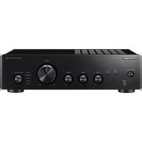
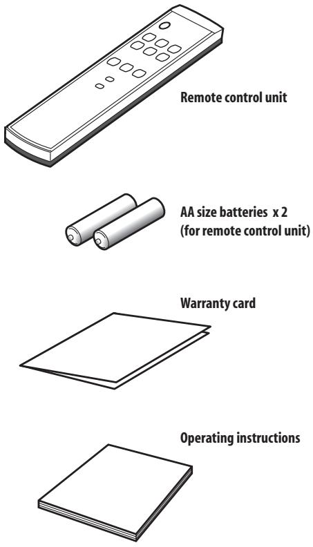
Chapter 4
Supplied accessories
Check that all of the following accessories are supplied in the box.
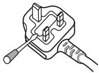
Power cord
Only the power cord appropriate for your country or region is supplied:

For UK and Republic of Ireland
Chapter 5 Part names
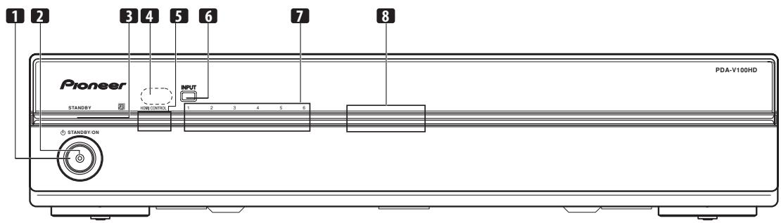
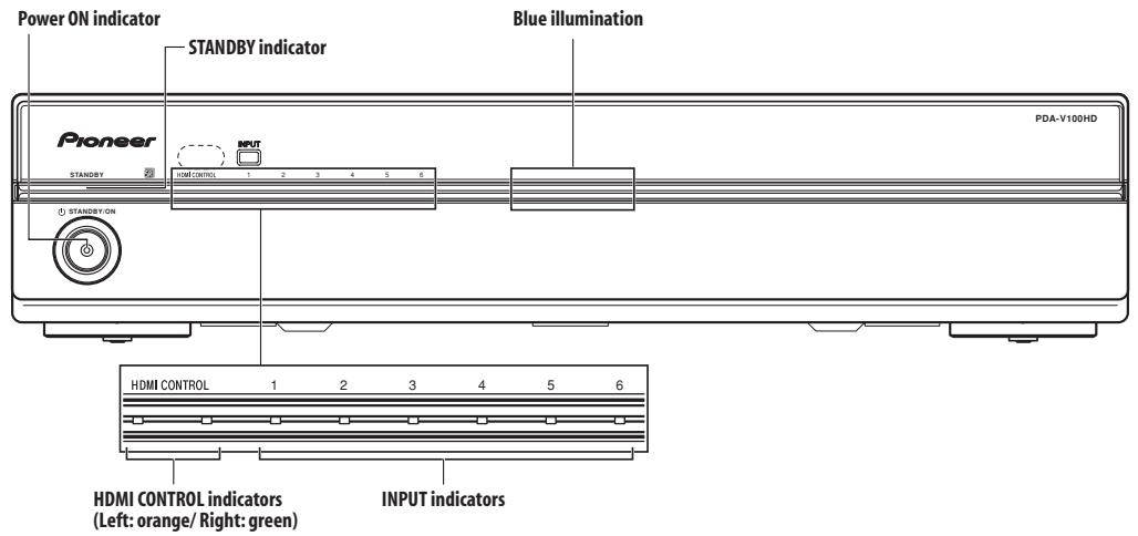
Front
Press to set power to ON/STANDBY.
2 Power ON indicator (blue)
Lights blue when unit power is turned ON.
3 STANDBY indicator (red)
Lights red when unit power is set to STANDBY.
4 Remote control unit sensor
Point the remote control unit at this sensor when operating.
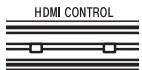
5 HDMI CONTROL indicators
(Left: orange/Right:green)
When this unit is connected to a plasma television, these indicators light under the following conditions:
a. PDP combination mode:
Lights green when HDMI CONTROL switch is set to ON, and the unit's connected plasma television can be operated using the latter's remote control unit. (See page 10.)
b. Independent 1 mode:
Lights orange when the HDMI CONTROL switch is set to ON. (See page 10.)
c. Independent 2 mode:
Do not light when the HDMI CONTROL switch is stet to OFF. (See page 10.)
Use to select the unit's source INPUT 1 to INPUT 6.
Notifies user of currently selected input and currently set mode.
8 Blue illumination
Lights blue when unit power is turned ON. Flashes blue during setting mode.
Rear
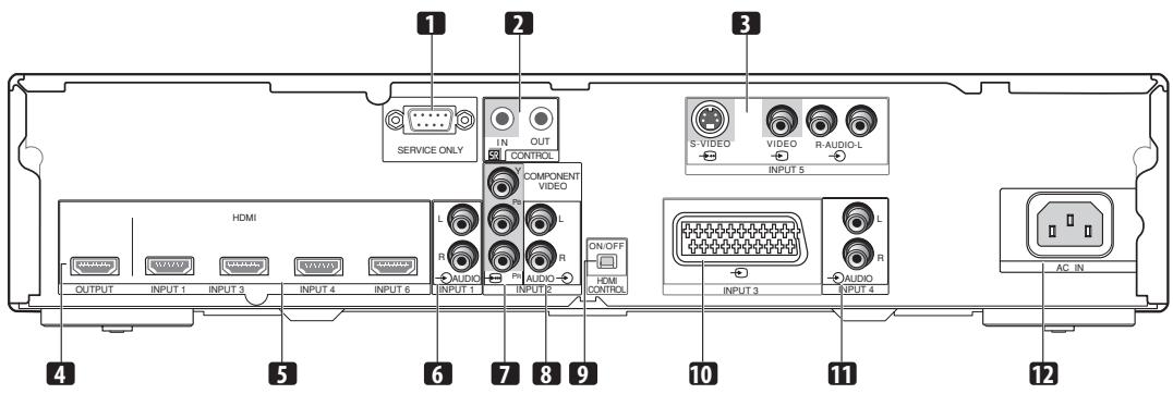
1 Factory adjust connector
Do not connect anything to this connector.
2 CONTROL IN/OUT connectors
Connect to Pioneer components bearing the SR mark.
Connect to the output connectors of components such as Blu-ray disc (BD) players, DVD players, DVD recorders, Set-Top Box (STB), VCRs, game machines, camcorders, etc.
4 OUTPUT connector (HDMI)
Connect to the HDMI connector of a television supporting the High-Definition Multimedia Interface (HDMI).
Connect to the HDMI connector of components supporting the High-Definition Multimedia Interface (HDMI), such as BD players, DVD recorders, etc.
Connect to a component's analog audio output connectors.
(COMPONENTVIDEO:Y,PB,PR)
Connect to the appropriate output connectors of a BD player, DVD player, DVD recorder, etc.
Connect to audio output connectors of BD player, DVD player, DVD recorder, etc.
9 HDMI CONTROL switch
Set to ON when this unit is connected to a Pioneer plasma television; set to OFF when connected to another manufacturer's television.
Connect to the appropriate output connector of a BD player, DVD player, DVD recorder, etc.
Connect to a component's analog audio output connectors.
12 AC IN
Connect one end of the supplied power cord to this connector, and the other end to a household AC outlet.
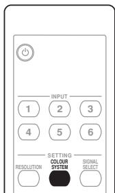
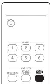
Remote control unit
Point the remote control at the unit to operate.
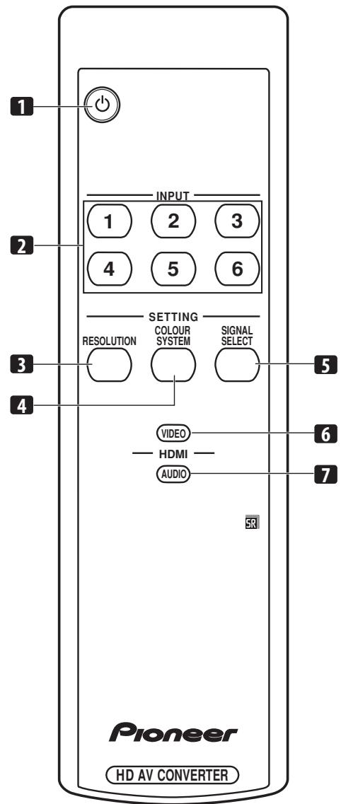
Press to set power to ON/STANDBY.
Press to select the unit's source INPUT 1 to INPUT 6.
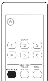
Use to set output resolution when converting analog input signals to HDMI. (See page 19.)
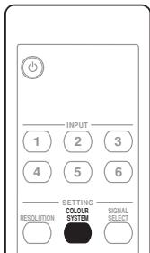
Use to set the colour system for analog input signals. (See page 19.)
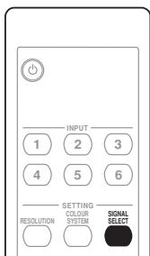
Use to select input signal for INPUT 3. (See page 19.)
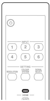
Use to set the colour format when converting analog input signals to HDMI. (See page 20.)
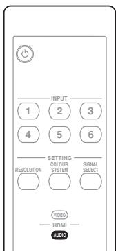
Use to set the type of audio signal during HDMI input. (See page 20.)
Chapter 6
Preparation
Installing the unit

Caution
- Do not place a VCR or any other device on the top of the unit.
- When installing, allow enough space on the sides and above the unit.
- Do not block the side ventilation opening or the rear exhaust opening of the unit.

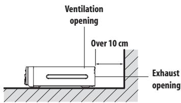

Caution
- Placing the unit alone in the vertical position can result in product damage and malfunction.

Preparing the remote control unit
Inserting batteries
1 Open the battery cover.
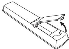
2 Load the supplied two AA size batteries while inserting their respective negative polarity (-) ends first.
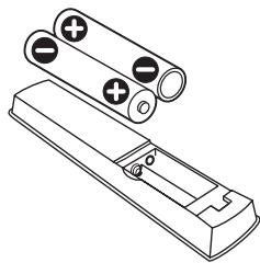
Place batteries with their terminals corresponding to the (+) and (-) indicators in the battery compartment.
3 Close the battery cover.


Caution
Improper use of batteries can result in chemical leakage or an explosion. Be sure to follow the instructions below.
- When you replace the batteries, use manganese or alkaline ones.
- Place the batteries with their terminals corresponding to the (+) and (-) indicators.
- Do not mix batteries of different types. Different types of batteries have different characteristics.
- Do not mix old and new batteries. Mixing old and new batteries can shorten the life of new batteries or cause chemical leakage in old batteries.
- Remove batteries as soon as they have worn out. Chemicals that leak from batteries can cause a rash. If you find any chemical leakage, wipe thoroughly with a cloth.
- The batteries supplied with this product may have a shorter life expectancy due to storage conditions.
- If you will not use the remote control unit for an extended period of time, remove the batteries from it.
- WHEN DISPOSING OF USED BATTERIES, PLEASE COMPLY WITH GOVERNMENTAL REGULATIONS OR ENVIRONMENTAL PUBLIC INSTITUTION'S RULES THAT APPLY IN YOUR COUNTRY/AREA.
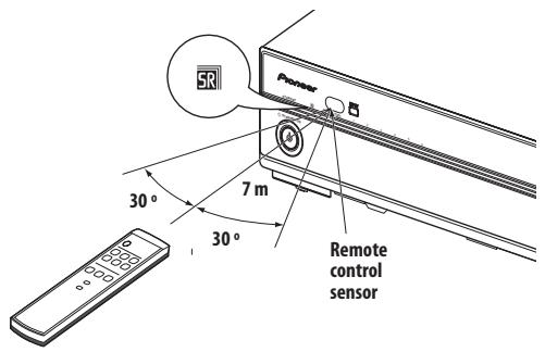
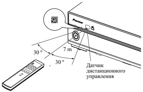
Operating range of the remote control unit
Operate the remote control unit while pointing it toward the remote control sensor (SR) located at the left of the front panel of the unit. The distance from the remote control sensor must be within 7 m and the angle relative to the sensor must be within 30 degrees in the right, left, upward, or downward direction.

Caution
- Do not expose the remote control unit to shock. In addition, do not expose the remote control unit to liquids, and do not place in an area with high humidity.
- Do not install or place the remote control unit under direct sunlight. The heat may cause deformation of the unit.
- The remote control unit may not work properly if the remote control sensor of the unit is under direct sunlight or strong lighting. In such case, change the angle of the lighting or unit, or operate the remote control unit closer to the remote control sensor.
- When any obstacle exists between the remote control unit and the remote control sensor, the remote control unit may not function.
- As the batteries become empty, the remote control unit can function within a shorter distance from the remote control sensor. Replace the batteries with new ones early enough.
Chapter 7
Using the unit
When a Pioneer plasma television is connected and the HDMI Control function is set, the plasma television's remote control can be used to perform normal operations on this unit.
When using the HDMI Control function, set the rear panel HDMI CONTROL switch to ON, then use the plasma television's "HDMI Control Setting" menu to set the television to permit control of the unit.
This unit can also be used as an AV selector, without using the HDMI Control function. In that case, leave the HDMI CONTROL switch set to OFF.
This unit has three operating modes when using the Pioneer HDMI Control function.
Each of the modes can be ascertained by looking at the status of the HDMI CONTROL indicators.
The unit's operations and operation restrictions are as follows:
| Operation modes | Operations/Operation restrictions | HDMI Control setting |
| PDP Combination Mode | Operations:
• HDMI Control function used for linked operation with Pioneer plasma television.
• Change input selections INPUT 1 to INPUT 5 using the remote control unit furnished with the Pioneer plasma television.
• Power on/off linked to plasma television using the remote control unit furnished with the Pioneer plasma television.
• When a video signal is received from a connected input component, this unit is automatically turned on and the input selector switched to allow output of the image from the connected component (HDMI inputs only).
Operation restrictions:
• The INPUT button on PDA-V100HD and its remote control unit are disabled.
• The component connected to INPUT 6 cannot be used. | Settings required on this unit:
HDMI CONTROL switch: ON
Settings required on the Pioneer plasma television: Set to allow linked operation with this unit. |
| Independent 1 mode | Operations:
• HDMI Control function is used to link operations with input component.
• When a video signal is detected from a connected input component, this unit is automatically turned on and the input selector switched to allow output of the image from the connected component (HDMI inputs only).
• Whether power off can be linked depends on functional support of other connected components (namely, whether power off command can be sent from other component).
• The INPUT button on PDA-V100HD and its remote control unit can be used to switch the unit's corresponding INPUT 1 to INPUT 6. | Settings required on this unit:
HDMI CONTROL switch: ON |
| Independent 2 mode | Operations:
• HDMI Control function is not used.
• The unit does not operate in linkage to other components, but as an independent component.
• The INPUT button on PDA-V100HD and its remote control unit can be used to switch the unit's corresponding INPUT 1 to INPUT 6. | Settings required on this unit:
HDMI CONTROL switch: OFF |
Connecting the unit to a Pioneer plasma television (see Chapter 8)
Operations, indicators, conditions, and precautions when connecting the unit to a Pioneer plasma television are as follows:
- See the section Features (page 7) regarding the model numbers of supported Pioneer plasma televisions.
| Operations | ·The plasma television's remote control can be used to control the unit's input selector.
·The unit's power switch is linked to that of the plasma television; when the plasma television's power switch is set to off, this unit's power is also automatically turned off. |
| Indicators | The HDMI CONTROL indicator lights green. |
| Conditions | ·The HDMI CONTROL switch must be set to ON.
·The plasma television's “HDMI Control Setting” menu must be set to allow control of this unit.
Note: For setting details, consult the Operating Instructions for your plasma television. |
| Precautions | ·The INPUT button and the remote control's INPUT (1 to 6) buttons cannot be used to change the unit's input selection.
·The input selection for the component connected to INPUT 6 connector cannot be changed.
·If the HDMI CONTROL switch is set from ON to OFF, be sure also to cancel the plasma television's “HDMI Control Setting”. |
Connecting the unit to other televisions (see Chapter 9)
Operations, indicators, conditions, and precautions when using the unit as an AV selector are as follows:
| Operations | ·The INPUT button and remote control's INPUT (1 to 6) buttons can be used to change the unit's input selection. |
| Indicators | The HDMI CONTROL indicators do not light. |
| Conditions | ·The HDMI CONTROL switch must be set to OFF. |
| Precautions | ·The plasma television's remote control cannot be used to control the unit's input selector. |
Chapter 8
Using the unit with a Pioneer plasma television
Follow these procedures when connecting this unit to a Pioneer plasma television.
The ability to use the HDMI Control function depends in part on the specifications of the plasma television; as a result, please consult the Operating Instructions for your plasma television if you desire to use HDMI Control.
Be sure that the power switches of both plasma television and this unit are set to off before making connections and settings.
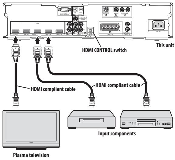
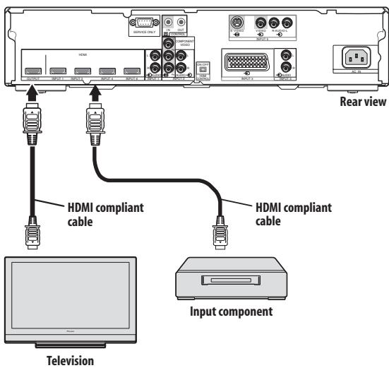
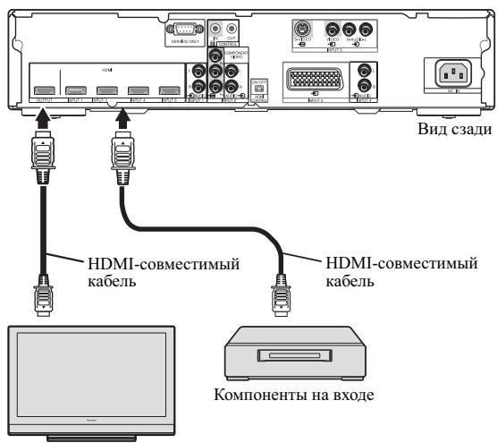
System composition example using HDMI connections
1 Set this unit's rear panel HDMI CONTROL switch to ON.

2 Connect this unit to other components.
-
Be sure power is turned off before making connections.
-
Regarding connections, see section Using with other components on page 21.
- When using the plasma television's remote signal receiver to control this unit, consult the section Connecting control cables on page 18.
3 Turn power on.
- Turn power on only after connecting all other components.
4 Confirm that the HDMI CONTROL indicator lights orange.

5 On the plasma television's "HDMI Control Setting" menu, set to allow control of this unit.
- For details, see the plasma television's Operating Instructions.
6 Confirm that the HDMI CONTROL indicator has changed from orange to green.

7 Select the input.
- Confirm that the input can be changed using the plasma television's remote control unit.
When turning power off:
If the plasma television's "HDMI Control Setting" menu is used to link the power controls, when the plasma television's remote control is used to turn the television's power off, this unit's power will simultaneously turn off.
Chapter 9
Using the unit with other televisions
Follow the procedures listed below when using this unit as an AV selector.
Be sure that the power switches of both television set and this unit are set to off before making connections and settings.
1 Set the HDMI CONTROL switch to OFF.

2 Connect this unit to other components.
- Be sure power is turned off before making connections.
- Regarding connections, see section Using with other components on page 21.
3 Turn power on.
- Turn power on only after connecting all other components.
4 Confirm that the HDMI CONTROL indicators are not lighted.
5 Select the input.
- Confirm that the INPUT button and the remote control unit's INPUT (1 to 6) buttons can be used to change the source input.
When turning power off:
Press the STANDBY/ON button or the remote control unit's button to turn power off.
Chapter 10
Advanced functions
Connecting control cables
Connect control cables between the unit and other Pioneer equipment having the SR logo. You can then operate the connected equipment by sending commands from its remote control unit to the remote control sensor on the unit.
After the CONTROL IN/OUT terminals have been connected, the remote control sensors on the connected equipment do not accept commands from the remote control units. Face the remote control units to the remote control sensors on the unit when operating the connected equipment.

Note
- Make sure that the power is turned off when making connections.
- Complete all component connections before making control cable connections.
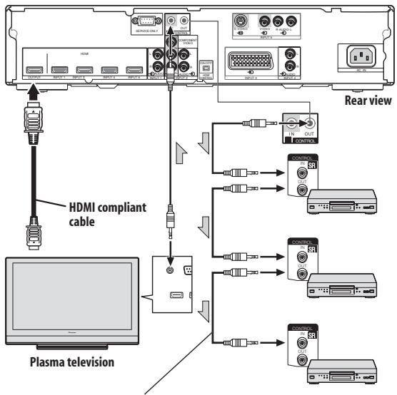
The control cables (commercially available) are mono sound cables with mini plugs (no resistance).

Note
- When connecting the control connector, be sure to simultaneously connect analog audio cables or video cables. System control will not operate properly when digital connections alone are made.
- When using SR connections to a Pioneer plasma television, point the unit's remote control at the plasma television's signal sensor when operating.
Changing settings
Changing HDMI output resolution
When converting analog input signals to HDMI, the output resolution must be set.
This setting is supported when the currently selected input is INPUT 2, INPUT 3 (SCART), or INPUT 5.
The following items can be set:
| Item | Description |
| Auto (default) | Resolution is set automatically in response to the input signal. |
| 480p/576p | Switch to 480p/576p resolution |
| 720p | Switch to 720p resolution |
| 1080i | Switch to 1080i resolution |

Note
- Under normal conditions, leave this set to Auto.
Selecting the colour system
Select the colour system for analog input signals.
This setting is supported when the currently selected input is INPUT 3 (SCART), or INPUT 5.
The system can be set to Auto (default), PAL, SECAM, NTSC, 4.43NTSC or PAL60.

Note
- Under normal conditions, leave this set to Auto.
Select the INPUT 3 source signal.
The signal can be selected from among VIDEO (default), S-VIDEO, RGB, or HDMI.
When converting analog input signals to HDMI, set the colour format.
The following items can be set:
| Item | Description |
| Auto (default) | Automatically sets the signal format in response to the input signal. |
| Colour-1 | Digital Component Video signals (4:2:2) locked |
| Colour-2 | Digital Component Video signals (4:4:4) locked |
| Colour-3 | Digital RGB signals (16 to 235) locked |
| Colour-4 | Digital RGB signals (0 to 255) locked |

Note
- Under normal conditions, leave this set to Auto.
When using an HDMI input, set the audio signal format.
This setting is supported when the currently selected input is INPUT 1 (HDMI), INPUT 3 (HDMI), or INPUT 4 (HDMI).
The following items can be set:
| Item | Description |
| Auto
(default) | Audio signal format is set automatically in response to the type of input signal. |
| Digital | Plays only HDMI digital audio. |
| Analogue | When both HDMI and analog connec-tors are connected, analog signals only are played. |

Note
- Under normal conditions, leave this set to Auto.
- This setting cannot be made for INPUT 6, since analog audio connectors are not provided.
Chapter 11
Using with other components
Connections to a television
Televisions supporting HDMI (High-Definition Multimedia Interface) can be connected.

Note
- When connecting this unit to a Pioneer plasma television supporting linked settings, set the rear panel HDMI CONTROL switch to ON. When connecting a television made by another manufacturer, set the HDMI CONTROL switch to OFF. (See page 10.)
- During PDP combination mode, input selection on the component connected to INPUT 6 cannot be selected, since the remote control unit supplied with the Pioneer plasma television is not furnished with an INPUT 6 button.
You can connect many types of input components to the unit, like a plasma television, BD player, DVD player, DVD recorder, set-top boxes, VCR, game console, camcorder etc.
To view images from an input component, select the input source using the INPUT (1 to 6) buttons on the remote control unit (see page 11). During PDP combination mode, use the plasma television's remote control unit to switch between inputs.

Caution
- To protect all components, always unplug the unit from the power outlet before connecting to a plasma television, BD player, DVD player, DVD recorder, set-top boxes, VCR, game console, camcorder or other components.
- Two or more units cannot be connected simultaneously.
The INPUT 1, 3, 4 and 6 terminals are HDMI terminals to which digital video and audio signals can be input. To use the HDMI terminal, activate the terminal and specify the types of video and audio signals to be received from the connected component. For the types of these signals, see the operation manual that came with the connected component.
Video signals supported
| 640 x 480 (VGA) 60 Hz |
| 720 x 480p@59.94 Hz/60 Hz |
| 720 (1440) x 480i@59.94 Hz/60 Hz |
| 720 x 576p@50 Hz |
| 720 (1440) x 576i@50 Hz |
| 800 x 600 (SVGA) 60 Hz |
| 1024 x 768 (XGA) 60 Hz |
| 1280 x 720p@50 Hz |
| 1280 x 720p@59.94 Hz/60 Hz |
| 1280 x 1024 (SXGA) 60 Hz |
| 1360 x 768 (Wide - XGA) 60 Hz |
| 1920 x 1080p@24 Hz |
| 1920 x 1080p@50 Hz |
| 1920 x 1080i@50 Hz |
| 1920 x 1080i@59.94 Hz/60 Hz |
| 1920 x 1080p@60 Hz |
Deep Colour supported
Deep Colour means the colour depth that describes the number of bits used to represent the colour of a single pixel in a bitmapped image. Besides the conventional RGB/YCbCr16 bit/20 bit/24 bit signals, the plasma television also supports RGB/YCbCr30 bit/36 bit signals. In this way, when a component supporting HDMI 1.3 Deep Colour is connected, signals can be transmitted and received without signal degradation.
Connections to a HDMI-supported component
Connect a HDMI-supported component to connectors INPUT 1 (HDMI), INPUT 3 (HDMI), INPUT 4 (HDMI), or INPUT 6 (HDMI).
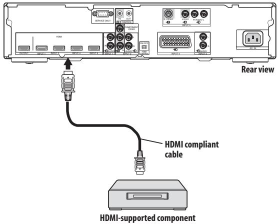
About HDMI
HDMI (High Definition Multimedia Interface) supports both video and audio on a single digital connection for use with DVD players, DTV, set-top boxes, and other AV devices. HDMI was developed to provide the technologies of High Bandwidth Digital Content Protection (HDCP) as well as Digital Visual Interface (DVI) in one specification. HDCP is used to protect digital content transmitted and received by DVI-compliant displays. HDMI has the capability to support standard, enhanced, or high-definition video plus standard to multi-channel surround-sound audio. HDMI features include uncompressed digital video, a bandwidth of up to 2.2 gigabytes per second (with HDTV signals), one connector (instead of several cables and connectors), and communication between the AV source and AV devices such as DTVs. HDMI, the HDMI logo and High-Definition Multi-media Interface are trademarks or registered trademarks of HDMI licensing LLC.
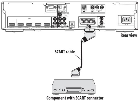
Connections to a component equipped with SCART connector
A component equipped with SCART connector can be connected to the INPUT 3 (SCART) connector.
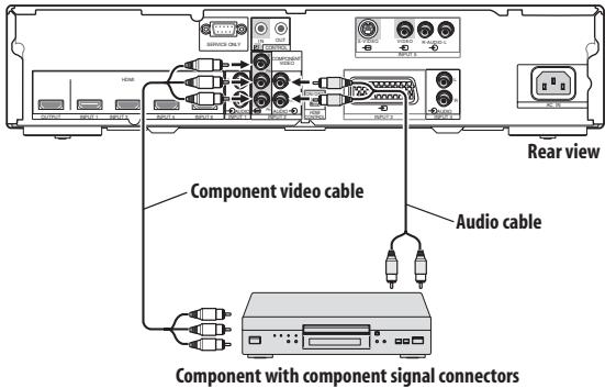
Connections to a component with component connectors
A component equipped with component signal connectors can be connected to INPUT 2 connectors (COMPONENT VIDEO).
Chapter 12
Troubleshooting
| Problem | Possible solution |
| STANDBY indicator doesn't light. | ·Is power cord correctly connected?
·Confirm whether the Power ON indicator lights. (See page 9.) If it doesn't light, the unit may be damaged; consult your Pioneer dealer or service station. |
| Can't use remote control unit to turn power on. | ·Check whether batteries are installed correctly in remote control unit. Try replacing with new batteries. |
| Video does not appear even when input is switched. | ·Confirm that input/output cables are connected correctly.
·Set television's input selector correctly. (See page 21.) |
| No video image appears from the component connected to INPUT 3. | ·Use this unit's remote control to make the INPUT 3 setting. (See page 19.) |
| No video image appears from the component connected to INPUT 6. | ·If the HDMI CONTROL indicator is lighted green (during PDP combination mode), it may not be possible to display the output from INPUT 6. For details, consult your plasma television's Operating Instructions. |
| No sound or video (HDMI) | ·This unit supports the HDCP standard. Confirm whether your input component supports HDCP. Depending on the input component, it may not be possible to make HDMI connections through this unit.
If the input component does not support the HDCP standard, use one of the other connection methods, either VIDEO, S-VIDEO, RGB, or COMPONENT. If you do not know the specifications of the input component, consult the component's manufacturer. |
| No video (HDMI, VIDEO, S-VIDEO, RGB, COMPONENT) | ·Confirm that input cables are correctly connected. |
| No video (HDMI) | ·Confirm that the input component's output setting is fixed at 480i or 576i. Set the input component's HDMI output setting for 480p or above. |
| Sound is heard, but no video can be seen. | ·Check connections. (See page 21.) |
| No sound (HDMI, VIDEO, S-VIDEO, RGB, COMPONENT) | ·Confirm that input/output cables are connected correctly.
·Confirm that the television's audio volume is set appropriately. |
| No sound (HDMI) | ·Use this unit's remote control to select the audio input source. (See page 20.) |
| No sound (when connecting using a cable to convert from DVI to HDMI) | ·Use an analog audio cable to connect the input component.
·Use this unit's remote control to select the audio input source. (See page 20.) |
| Sound is distorted. | ·Replace connection cable.
·Confirm that the input component is set correctly. |
| Video images from analog inputs are not displayed properly.
Video is distorted. | ·If distortion occurs in the input component's video signal (like when performing fast forward), depending on the video quality, some distortion may appear, or the image may cease to appear properly.
The same symptoms may also appear depending on the performance of the television.
Also check the following settings on this unit:
·Is the colour system set properly? (See page 19.)
·If INPUT 3 is selected, is the input signal set correctly? (See page 19.)
·Is the colour format set correctly? (See page 20.) |
| Can't make settings | ·See the section Changing settings on page 19. |
| Remote control unit doesn't respond. | ·Check remote control unit's batteries; if depleted, replace with new. (See page 12.)
·If too distant from the receiver, move closer. (See page 13.)
·If an obstacle is located between the remote control unit and the signal receiver, remove the obstacle. (See page 13.)
·If a bright fluorescent lamp or other light is shining on the remote signal sensor, remove the light fixture farther away. (See page 13.) |
| Remote control unit doesn't respond (SR connection) | ·When using SR connections, point this unit's remote control at the signal sensor on the plasma television to operate. When SR connections are not used, operate this unit's remote control while pointing it at the signal sensor on PDA-V100HD itself. (See page 18.)
·The remote control unit will not operate when a control cable is connected to the CONTROL IN connector. Confirm that a control cable has not been inserted to the CONTROL IN connector. (See page 18.)
·Confirm that the connector is not connected to the connector of another manufacturer's component having the same function. (See page 18.) |
| Remote control unit doesn't respond (PDP combination mode) | ·During PDP combination mode (HDMI CONTROL indicator lights green), INPUT (1 to 6) buttons on this unit's remote control are not supported. This is not a malfunction.
·When not using PDP combination mode (HDMI CONTROL indicator lights orange or doesn't light), the plasma television's remote control unit cannot be used for controlling operations. |
| Power ON indicator flashes blue | ·Try disconnecting the power cord from its power outlet then reconnecting it (do not repeat this numerous times). If the symptom persists, consult your Pioneer dealer or service station. |
| Even after making settings with the remote control unit, the corresponding indicators don't light. | ·Are you attempting to make settings that are not supported?
Perform only those settings that are supported. (See page 19.) |
SCART pin assignments
Various audio and video devices may be connected via the SCART terminals.
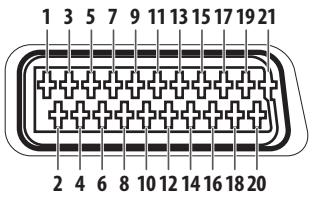
| SCART (INPUT 3) |
| 1 | Not used | 2 | Audio right input | 3 Not used |
| 4 | Common earth for audio | 5 | Earth for Blue | 6 Audio left input |
| 7 | Blue input | 8 | Not used | 9 Earth for Green |
| 10 | Not used | 11 | Green input | 12 Not used |
| 13 | Earth for Red | 14 | Earth for Red/Green/Blue control | 15 Red input |
| 16 | Red/Green/Blue control | 17 | Not used | 18 Earth for Video input |
| 19 | Not used | 20 | Video input | 21 Plug shield |
Specifications
| Power Requirements | 220 V to 240 V AC, 50 Hz/60 Hz, 12 W (0.4 W Standby) |
| Dimensions | 420 mm (W) x 90 mm (H) x 299 mm (D) |
| Weight | 3.3 kg |
| Colour System | PAL/SECAM/NTSC/4.43 NTSC/PAL 60 |
| Terminals Rear | INPUT 1 | HDMI in *1, AUDIO *3 |
| INPUT 2 | COMPONENT VIDEO, AUDIO |
| INPUT 3 | SCART *3 (AV in, S-VIDEO in, RGB in), HDMI in *1*3 |
| INPUT 4 | HDMI in *1, AUDIO *3 |
| INPUT 5 | S-VIDEO in, AV in |
| INPUT 6 | HDMI in *1*2 |
| CONTROL IN/OUT | 1 |
| OUTPUT | HDMI out *1 |
1 This conforms to HDMI1.3 and HDCP1.1. HDMI (High Definition Multimedia Interface) is a digital interface that handles both video and audio using a single cable. HDCP (High-bandwidth Digital Content Protection) is a technology used to protect copyrighted digital contents that use the Digital Visual Interface (DVI).
2Not supported during PDP combination mode
^*3 Switchable
Design and specifications are subject to change without notice.
Trademarks
HDMI, the HDMI logo and High-Definition Multimedia Interface are trademarks or registered trademarks of HDMI Licensing LLC.
Operation of the unit's indicators
Indicators appear as follows during operation and setting mode:
During normal operation
PDP combination mode
| Condition | Power ON indicator | STANDBY indicator | HDMI CONTROL indicators | INPUT indicators | Blue illumination | Remarks |
| Power ON | Lights blue | Off | Lights green | Only currently selected input lights | Lights blue | |
| ● | ● | ● | Depends on relevant settings | ● | (See chart “During setting mode”) |
| Power ON (setting mode) | | | | | | |
| STANDBY | Off | Lights red | All off | All off | Off | |
| ● | ● | ● | ● | ● | ● |
Independent 1 mode
| Condition | Power ON indicator | STANDBY indicator | HDMI CONTROL indicators | INPUT indicators | Blue illumination | Remarks |
| Power ON | Lights blue | Off | Lights orange | Only currently selected input lights | Lights blue | |
| ● | ● | ● | Depends on relevant settings | ● | (See chart “During setting mode”) |
| Power ON (setting mode) | | | | | | |
| STANDBY | Off | Lights red | All off | All off | Off | |
| ● | ● | ● | ● | ● | ● |
Independent 2 mode
| Condition | Power ON indicator | STANDBY indicator | HDMI CONTROL indicators | INPUT indicators | Blue illumination | Remarks |
| Power ON | Lights blue | Off | All off | Only currently selected input lights | Lights blue | |
| ● | ● | ● | Depends on relevant settings | ● | (See chart “During setting mode”) |
| Power ON (setting mode) | | | | | | |
| STANDBY | Off | Lights red | | All off | Off | |
| ● | ● | | ● | ● | ● |
During setting mode
For about five seconds after pressing the remote control unit buttons to enter a setting mode, the indicators will appear as noted below:
When the setting mode ends, the unit will return to power ON mode for ordinary operation.
(*) Factory default settings
When setting HDMI output resolution (when RESOLUTION button is pressed.)
| Item | INPUT indicators | Blue illumination | Indicator status |
| Auto (*) | 1 | 2 | 3 | 4 | 5 | 6 | Flashes blue | • When power ON.
• When currently selected input is INPUT 2, INPUT 3*, or INPUT 5.
* When setting the type of component connected to SCART connector. |
| 480p/576p | 1 | 2 | 3 | 4 | 5 | 6 |
| 720p | 1 | 2 | 3 | 4 | 5 | 6 |
| 1080i | 1 | 2 | 3 | 4 | 5 | 6 |
When setting colour system for analog signals (when COLOUR SYSTEM button is pressed.)
| Item | INPUT indicators | Blue illumination | Indicator status |
| Auto (*) | 1 | 2 | 3 | 4 | 5 | 6 | Flashes blue | • When power ON.
• When currently selected input is INPUT 3*, INPUT 5.
* When setting the type of component connected to SCART connector. |
| ● | ● | ● | ● | ● | ● |
| PAL | 1 | 2 | 3 | 4 | 5 | 6 | | |
| ● | ● | ● | ● | ● | ● | |
| SECAM | 1 | 2 | 3 | 4 | 5 | 6 | | |
| ● | ● | ● | ● | ● | ● | |
| NTSC | 1 | 2 | 3 | 4 | 5 | 6 | | |
| ● | ● | ● | ● | ● | ● | |
| 4.43 NTSC | 1 | 2 | 3 | 4 | 5 | 6 | | |
| ● | ● | ● | ● | ● | ● | |
| PAL 60 | 1 | 2 | 3 | 4 | 5 | 6 | | |
| ● | ● | ● | ● | ● | ● | |
When selecting INPUT 3 source signal (when SIGNAL SELECT button is pressed.)
| Item | INPUT indicators | Blue illumination | Indicator status |
| VIDEO (*) | 1 | 2 | 3 | 4 | 5 | 6 | Flashes blue | · When power ON.
· When currently selected input is INPUT 3. |
| ● | ● | ● | ● | ● | ● | ● |
| S-VIDEO | 1 | 2 | 3 | 4 | 5 | 6 | | |
| ● | ● | ● | ● | ● | ● | | |
| RGB | 1 | 2 | 3 | 4 | 5 | 6 | | |
| ● | ● | ● | ● | ● | ● | | |
| HDMI | 1 | 2 | 3 | 4 | 5 | 6 | | |
| ● | ● | ● | ● | ● | ● | | |
When setting HDMI video signal format (when VIDEO button is pressed.)
| Item | INPUT indicators | Blue illumination | Indicator status |
| Auto (*) | 1 | 2 | 3 | 4 | 5 | 6 | Flashes blue | · When power ON.
· With all inputs. |
| ● | ● | ● | ● | ● | ● | ● |
| Colour-1 | 1 | 2 | 3 | 4 | 5 | 6 | | |
| ● | ● | ● | ● | ● | ● | | |
| Colour-2 | 1 | 2 | 3 | 4 | 5 | 6 | | |
| ● | ● | ● | ● | ● | ● | | |
| Colour-3 | 1 | 2 | 3 | 4 | 5 | 6 | | |
| ● | ● | ● | ● | ● | ● | | |
| Colour-4 | 1 | 2 | 3 | 4 | 5 | 6 | | |
| ● | ● | ● | ● | ● | ● | | |
When setting HDMI audio signal format (when AUDIO button is pressed.)
| Item | INPUT indicators | Blue illumination | Indicator status |
| Auto (*) | 1 | 2 | 3 | 4 | 5 | 6 | Flashes blue | · When power ON.
· When currently selected input is INPUT 1,
INPUT 3*, or INPUT 4. |
| ● | ● | ● | ● | ● | ● |
| Digital | 1 | 2 | 3 | 4 | 5 | 6 | | * When setting the type of component
connected to the HDMI connector. |
| ● | ● | ● | ● | ● | ● | |
| Analogue | 1 | 2 | 3 | 4 | 5 | 6 | | Note: The operations listed are not performed
when INPUT 6 is selected. |
| ● | ● | ● | ● | ● | ● | |
Unsupported settings (when a remote control unit button not supported by currently selected input is pressed.)
| INPUT indicators | Blue illumination | Indicator status |
| - | 1 | 2 | 3 | 4 | 5 | 6 | Flashes blue | ·When power ON. |
| | | | | | | | |
Published by Pioneer Corporation.
Copyright © 2007 Pioneer Corporation.
All rights reserved.
IMPORTANT

PDP-SX5080D/PDP-SX4280D
PDP-LX5080D/PDP-LX6080D
PDP-508XD/PDP-428XD
PDP-LX508D/PDP-LX608D
Chapitre 4
Accessoires fournis
Publication de Pioneer Corporation.
© 2007 Pioneer Corporation.
PDP-SX5080D/PDP-SX4280D
PDP-LX5080D/PDP-LX6080D
PDP-508XD/PDP-428XD
PDP-LX508D/PDP-LX608D
Kapitel 4
c. Modus Independent 2:
PDP-SX5080D/PDP-SX4280D
PDP-LX5080D/PDP-LX6080D
PDP-508XD/PDP-428XD
PDP-LX508D/PDP-LX608D
Capitolo 4
Copyright © 2007 Pioneer Corporation.
PDP-SX5080D/PDP-SX4280D
PDP-LX5080D/PDP-LX6080D
PDP-508XD/PDP-428XD
PDP-LX508D/PDP-LX608D
Capúlico 4
Copyright © 2007 Pioneer Corporation.
PDP-SX5080D/PDP-SX4280D
PDP-LX5080D/PDP-LX6080D
PDP-508XD/PDP-428XD
PDP-LX508D/PDP-LX608D
TnaBa 4
4 PpneMHbI DaTcNk NylbTa DnCTaHcNoHOrO ynpabJIeHnA
Pn pa6oTe c nyIbTOM nCTaHIOHO yIpaBJIeHnaIIpaBJIyTe eO Ha 3OT daTPhK.
5 INDnKaToPbI HDMI CONTROL
(Левы: opaнхебы/ npabby: 3eilehby)
Korda daHHoe ycTpoIcTBO IOIOcoEINHeNO K IIJIa3MeHHOMy TeJIeBn3OpY, 3TN HINKaTOPbI 3aRopaHOTcB CJIeDyUOIIHX cHTyaIIHX:
a. Pexim CB3n PDP:
Tognt 3eJIeHbIM IcBToM, KOrIa IIpeEJIIOuHaTeJIb HDMICONTROL yCTaHOBJIeH B IIOJOKeHne ON INIOIKJIIOUeHHb KycTroPoiCTBy IIAJ3MeHbI TeJIeBH3Op MOJEt YIpaJIbIaTbc C IOMOIIbO IyJIbTaIINCTaHUNHOY OYIpaBIeHnI IOCLJeIHero.
(CM. ctp. 10.)
b. He3aBnCmbl peKIM 1:
3aropaeTc npaHKeBbI IBeTOM, KOrJa IpeKJIIOuAteJIb HDMI CONTROL yCTaHOBJeH B IIOJIOKeHHe ON. (Cm. ctp. 10.)
c. He3aBnCmbl pexm 2:
He ropt, KOrIa IpeKJIIOuAteJIb HDMICONTROL yctaHOJIeH B IIIOJIOKeHne OFF. (CM. cTp. 10.)
HcIOJIb3yETcIJIa BbIbOpa HcTOUHHKa BXoDHOrO cHrHaJIa Ha yCtpoiCTBO c INPUT 1 IIO INPUT 6.
7 INDnKaTOpbl BXOIOB
H3BeeIaHT IOJIb3OBaTeJIa O TeKyuIeM BbIbpaHHOM BXOJe H TeKyuIeM 3aJaHHOM peKHe.
8 CnHya nOoCBetKa
FopHT cHHM IBeTOM, KOrJa IIITaHHe ycTpOiCTBa BkJIIOUeHO. MnraET cHHM IBeTOM BpeKHM HAcTpOiKH.
3aHnnaHeJIb

1 Pa3bEm dIJI 3aBODcKo HAcTpoKu
Hnue He IIOcoeHHaTe K 3tOMy pa3bemy.
2 Pa3beMbI CONTROL IN/OUT
Плдсоевинаянту К молноентам пюнзвдства Pioneer,在КOTорьх НмeeТса МаркнрOBka
Полсоелнгий К bblxOДнБIM pa3beMaM taKHX KOMПОHeHToB,ΚАК ПОИrgрьВATEJIIN IINCKOB Blu-ray (BD), DVD-ПОИrgрьВATEJIIN, DVD-pekoIepbI, KOMПИБOTepHbIe IIpHCTaBKN (STB), BnIeOMaHHToΦOHbI, INrpoBbIe IIpHCTaBKN, BnIeOKaMEpbI H T.Д.
4 Pa3bem OUTPUT (HDMI)
PoiocoeHHnIe K pa3bemy HDMI TeJIeBn30pa, PoiIepKHBaIOJero INHTepfeic High-Definition Multimedia Interface (HDMI).
ПолбоeINHЯITE К раЗьемam HDMI KOMПОHEHTOB, ПОДержИВАОПИХ ИНТЕРсс High-Definition Multimedia Interface (HDMI), тaknx кak BD-PионгрьвATEH, DVD-pekoidepbi T.Д.
IIOIcOeHNHnTe K BbIXoNDHbIM aHaJIoTOBbIM ayIHpOa3bEmam Ha KOMIIHOHeTe.
COMPONENTVIDEO:Y,PB,PR
ПолбоевпгийтЕ К COOTBEТСТВИОПМ BБIXODHbIM pa3ьемам BD-ПОНгрьIBaTeЯ, DVD-ПОНгрьIBaTeЯ, DVD-pekoДера n.T.Д.
Полбоeнняг Te K bixOДнIbI m ayДиHopa3beMaM BD-пронгьВаTeJI, DVD-пронгьВaTeJI, DVD-pekoДер aT.Д.
9 IpekeJIIOUATEJB HDMI CONTROL
YcTaHaBJIHbAaTe B IOJIOKeHHe ON, KOrIaJaAHHoe yCtpoiCTBO IIOIcoEINHEo K IIJa3MeHHOMy TeJIeBH3Opy IIpoHN3BOOCTBa Pioneer; yCtHaHaBJIHbAaTe B IOJIOKeHne OFF, KOrIa YcTpoiCTBO IOIcoEINHEo K TeJIeBH3Opy IpyrOTo IpoN3BOOHTeJIa.
HnpaBnHbnaKcIIyataaHa 6aTaapeek MoKe T npHBecTN K IIpoteKaHHIO XHMueckNX BeIeCTB HIN K B3pbBy.
O63aTeJbHO BbIIOJIHЯI Te npHBeEHbIe BHN3y yKa3AHn.
-Пинзаме He 6aTapeeK HIOJIb3yIte ToJIbKO mRaHHeBbIe HIN IIEJIOUHbIe 6aTapeiKn.
- IIpy yctaHOBKe cJIeIHTe 3a TeM, YTO6 IIOJIocA 6aTaapeek COOTBETCTBOBAJIN MapKHPOBKe (+) I(-).
- He HcnoJIb3yIte BmecTe 6aTapeKn pa3HbIX TINIOB. BaTapeKn pa3HbIX TINOB HMeIOT pa3HbIe XapaKTepHcTNIK.
He HcIOJIb3yIte BmecTe cTapBie H HOBbIe 6aTapeiKn. CMeIIaHHoe HcIOJIb3OBAHne cTapBIX HOBbIX 6aTapeek MOKET IIpHBecTH K COKpaIIeHNIO cPoka CJlyK6bl HOBbIX 6aTapeek HJIN BBI3BaTB IPOTEKaHne XHMnueckKHX BeIeCTB H3 cTapBIX 6aTapeek.
YdaJIaIte pa3pJaKeHHbIe 6aTaapeHKn KaK MoKHO 6bIcTpe. XHMnueckHe BeIeCTBa, IpoteKaIOIIne H3 6aTaapeek MOrYT BbI3bIaTb pa3IpaJKeHHe KOHN. B cLIyae o6HapUKeHHN IIpoTeKaHn, TIIaTeJIbHO BbITPHTe BbITeKaIOIIyO KHNKOCTb TkAHBIO.
- BaTapeiKN, IIOcTabJIeMbIe B KOMIIJEKeTte JaHHORO H3JeJHn, MOrY HmEt b MehBIIHN cPoK cJIyK6bI H3-3a ycIOBn XpaHeHn.
- EcIN BbI He IIaHpyeTe HcIIob3ObaT bIyIbT IInCTaIHIOHOYIIpaBJIeHnB TteYeHHe JInTEJbHOIepHOJaBpeMeHH, BbIbTe H3 Hero 6aTaapeKn.
- BbINOJIHЯITE YTNJIN3AUJIIO
ИСПОЛьЗOBAHbIX BATAPEEK B
COOTBETCTBIMN C
ПРABINTIbCTBEHHbIMN
ПОCTAHOBJIENHЯМN ИЛ ПИNHЯТыIMN
ПРABINJAMN B OTHOUSHEN NOXPAHbI
OKPYKAIOUSEI CPEДbl, ПРIMEHbIMbIMN B
BAшЕ CTPAHE/MECTHOCTN.
Pa6oyn dHaana30H nylbTa DnCTaHcNoHHoro ynpaBJeHna
Ipn pa6oTe c IyIbTOM dNCTaHIOHOHO yIpaBJIeHHaIpaBJIaIte erO ha IpnHeMhI daTtHKn dNCTaHIOHOHO yIpaBJIeHHa (S),pacIOJIOKeHHb B JIEBOY qactn IpeJeHN IaHeHH yCtpoiCTBa.PacctOReHne Do DaTtHuKa dNCTaHIOHOHO yIpaBJIeHHa DOJIgKHO 6bITb He 6OJIee 7 M, aYrOJI OTHOCHTeJIbHO daTtHuKa DOJIgKeH 6bITb B IpeJeJax 30 rpaIycOB H aHaIpaBJIeHHx BIPaBO, BJIeBO, BBepx HJIN BHN3.

Ppeynpexdene
Pa60ta, INHINKaTOpbI, COCTOHN H MepbI IpeIOCTOPOXHOCTH IIpr IIOKJIIOUeHN N daHHORO yCTPOJcTBa K IJIa3MeHHOMy TeJeBn3OpY IpoHN3BOJcTBa Pioneer OINcaHbI HNKe:
- Homepa MoJIeJIe IIOJIepeKHeBaEMbIX IIJa3MeHHbIX TeJIeBn3OpOB IIpoH3BOJcTBA Pioneer cM. B pa3JIeIe ΦyHKuOHaIbHbIe 603MOJxHocMu (ctp. 7).
| Рабota | • ПлJBТ ДИСТАПОННОУ упраьLEнЯ ПЛДМЕнHOrо TEЛБЕH3Орma может ИСПОЛБ3OBaTBСДЯ
ураьALEня сеLEКТорOM BxOJOВ на ДИНHom uctpoiCTBE.
• ВыкЛIOЧATEЛ Б ПИТАнЯ uctpoICTBa CBY3AN C BИКЛIOЧATEЛЕМ ПИТАнЯ ПЛДМЕнHOrO TEЛБЕH3Орma:
КогДA BИKЛIOЧATEЛ Б ПИТАнЯ ПЛДМЕнHOrO TEЛБЕH3Орma может ИСПОЛБ3OBaTHСДЯ
ПИТАнЯ, ПИТАнHE ДИнHOrO uctpoICTBa ТAKKE ВыкЛIOЧаETСЯ. |
| Индikatopbl | Индikatop HDMI CONTROL 3aRopaetcra 3eJIeHbIM ICBETOM. |
| Состонnia | • ПиЕКЛIOЧATEЛ B HDMI CONTROL ДИЛЖЕн 6blT bYCTAHOBIIeB IN BOLOJGEHne ON.
• Heo6XODHMBO BIIIOJIINHb NaCTPOIky B MeHNo "YCTAHOB.yIpN.HDMI" ПДМЕнHOrO TELEBnH3Opa,
чTO6bl pa3peIHTb UpRAblENHe ДИНbIM uCTpoIcTBOM.
ПИрMчaHne: 3a ПОДрБнIM OПИСАнHem NaCTPOEk образиITecь K ИСТРуКUПи NO 3KCIJIyAtaци
ДЯ BAIIERO ПЛДМЕнHOrO TELEBnH3Opa. |
| Пре dioctepeженя | • КнОПКΑ INPUT И KHOПКΙΝΥРΗΝΑСΤΑДИЗИПΟΥРΑВΙЕнna He могут
ИсПОЛБ3OBaTbCSДЯ Bly6Opa BxOJa.
• ВыбOPв BXOДАДЯ KMIOHENTa, ПОДcoEДИнEHORO K pa3bEMy INPUT 6, He может 6bl TИЗMeHEn.
•ЕсДI ПиЕКЛIOCHATEЛ B HDMI CONTROL ПиЕВОДITСЯ ИЗ ПОДLOJeHnA ON B ПОДLOJeHne OFF,
обЯЗATeJIbHo OTmehInTe NaCTpoIky "YCTAHOB.yIpN.HDMI" Na ПИЗМeHHom TELEBnH3Ope. |
CJIeJyIte OIIINcaHHbIM 3IdecB IIpoIeIpyam IIpi IIOIKJIIOUeHNN DAHHORO yCTpOJIcTBA K IIJa3MeHHOMY TeJIeBn3OpY IIPOH3BOJcTBA Pioneer.
Bo3MOxHOCtB HcIOJIb3OBAHnH yHKINH yIpaBJIeHNH HDMI YacTHNuHO 3aBNCHT OT TexHHueckHX XapaKTEpHCTNK IIa3MeHHORo TeJIeBH3Opa; IIO3TOMY, ecJIN Bbl JeJIaTe HcIOJIb3OBAbTyIpaBJIeHne HDMI, o6paTHTecb K HHCTpyKIIHNIO 3KcIIyatauHN IJIaBIIeRO IIa3MeHHORo TEJIeBH3Opa.
IpeBbIIIOJIHeHHeM IOIOCoEIMHeHH N HaCTpoek 6eHTecb TOM, YTO BbIKIOUaTeJIN IITaHHN KaK IIJa3MeHHOrO TeJIeBH3opa, TaK IN DaHHORO yCTpoiCTBa yCTaHOBJEHBIIOJOKeHNE BbIKIOUoEHN IITaHHN.
Ppimep KOHpyraun CnCTembIc NOMOJIbIO coeHNHeHH HDMI
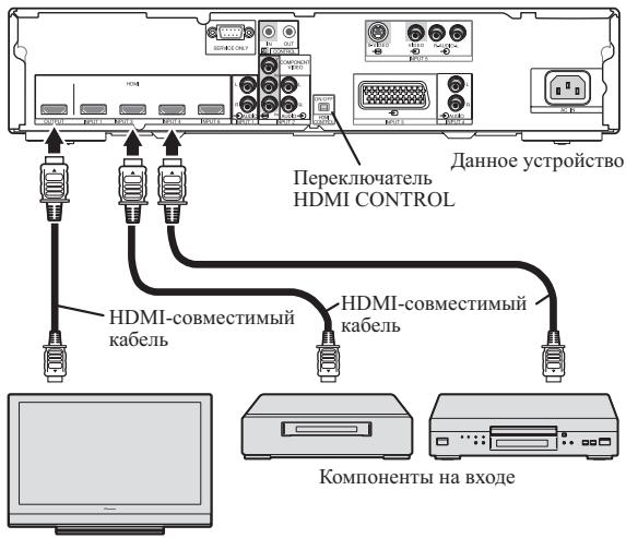
IIa3MeHHbI TeJIeBn3Op
1 YctaHOBtpe nepeKJIuOaTeJb HDMI CONTROL Ha 3aHei NaHeI DaHHoro yCTpojCTBa B noLoXeHne ON.

2ПодсоeДиHHTeДaHHoe yCtpoIcTBo KДpyrIMKOMNoHEHTam.
-
IpeJ BbIIOJIHeHHeM CoeJIHHeHn y6eJIHTecb TOM, YTO IIITaHHe BbIKJIHOyeHO.
-
HhΦopMaHIO O coeHHeHHx CM. B pa3JeIe IcnoJIb3ObaHue c dpyzmu KomnoHeHmaMu Ha cTp. 22.
3a HnHΦopMaIneiO6 HcIIb3OBaHHN IIpHemHOrO yctpoIcTBA cHHaJIa IINCTaHIOHOYipABJeHHN IJa3MeHHOTo TEJEBH3OpaI JyIPaBJIeHHN DaHHbIM ycTPOIcTBOM oBaIIaIaTeCb K pa3JeIy IodcoedunHeue KaobeluynpaBJIeHHa cTp.19.
3 BkJIIOUHTe NITaHne.
BkIIOuAHTe IITaHHe TOJIbKO IIOcJIe IIOJCOEINHeHHy yctpoiCTBa KO BcEM dpyHM KOMIIHOHEHTAM.
4 Y6eIntecb B TOM, yTO INHnkaTOp HDMI CONTROL ropnt opaHXeBBIM cBeTOM.

5 MeHIO "YcTaHOB. ynp. HDMI" nla3MeHHoro TeJIeBn3Opa dOJXHO 6bITb HAcTpoEHO TaKIM O6pa3OM, qTO6bI pa3peWntb ynpaBHeHne daHHbIM ycTPOIcTBOM.
3a IIOIpo6HOH HOpMaIIHeI O6paIIaTecb K HNCTpyKIIHN IO 3KcIIyataHH IIa3MeHHOro TeJIeBH3Opa.
6 YeDuTeCb B Tom, YTo CBeT INDkaTopa HDMI CONTROL n3MeHnIcC opAHKeBOrHa 3eJIeHbI.

7 BbIbepeTBeXoJd.
- Y6eIHTecb TOM, YTO BbIbOp BXOJa MOKeT 6bITb H3MeHeH C IIOMOIIbIO IYJIbTa IINCTaHIIOHHOTo yIpaJIeHnI IIa3MeHHOrTo TeJIeBH3Opa.
PnBbIKHoueHHN nHTaHn:
MeHIO "UcTaHOB.yIip.HDMI" HcNoJIb3yETcTg IJIa CB83bIBaHHN yIIPAbJIeHHN IITaHHM, YTO IIO3BOJIaTeO IIOHBpeMeHHO OTKJIIOuATb IIITaHHe DaHHORO ycTpoIcTBa C BbIKJIIOueHHM IITaHHN IIIA3MeHHORo TeJEBH3Opa C IIOMOIIb IOIyIbTa INCTaHHIOHHORO yIIPAbJIeHHN IIIA3MeHHORO TeJEBH3Opa.
TnaBa 9
- IIpeIIOHTTeJIbHO OCTaJIaIte BbI6paHHbIM IyHKT ABTO.
Bb6op zBeTOBcNCTeMbI
Bb6epHTe 1BcETOByIO CnCTeMy IJIaHaJIOTOBbIX BXOINbIX CNHbIOB.
3Ta NaHcTpoKa IIOJIePKeHbAeTcR, KOrIa B KaueCTBe TeKyuIeRo BVbIbpaHHoR BoXOJa 3aJauH BxoI INPUT 3 (SCART) HIN INPUT 5.
- Haxmte KhoNky COLOUR SYSTEM Ha npJIbTe DnCTaHcNoHOro ynpabJeHn.
- IIpeIIOHTeJIbHO OCTaJIaIte Bbl6paHHbIM IyHKT ABTO.
BbIbepHTe BxOJHO CnIHHaIIA IINPUT 3.
- Haxmte KhoNky SIGNAL SELECT Ha npJIbTe ductaHOnHHoro ynpabLeHn.
- IIpeIIOHTTEJIbHO OCTaBIAITe BbI6paHHbIM IyHKT ABTO.
- 3Ta Hactpoika He MoKeT 6bItb BbIIOJIHeHa IJI BxOJa INPUT 6, TaK KaK IJIa Hero He IpeDyCMOTpeHb pa3bEmbl IJIa aHaJIIOBbIX ayINOCHTHaJIOB.
Глaba 11 ИспOLSьЗОВане с ДругимКOMПОHENTамN
TeJIeBn3Op
H3daHo Pioneer Corporation.
3a\Pi\Pi HO aBTopcKm IpaBOM ©. 2007 Pioneer Corporation.
Bce npaba coxpahehbl.
Discover the benefits of registering your product online at http://www.pioneer.co.uk (or http://www.pioneer.eu)
PIONEER ELECTRONICS (USA) INC.
P.O. BOX 1540, Long Beach, California 90801-1540, U.S.A. TEL: (800) 421-1404
PIONEER ELECTRONICS OF CANADA, INC.
300 Allstate Parkway, Markham, Ontario L3R 0P2, Canada TEL: 1-877-283-5901, 905-479-4411
PIONEER EUROPE NV
Haven 1087, Keetberglaan 1, B-9120 Melsele, Belgium TEL: 03/570.05.11
PIONEER ELECTRONICS ASIACENTRE PTE. LTD.
253 Alexandra Road, #04-01, Singapore 159936 TEL: 65-6472-7555
PIONEER ELECTRONICS AUSTRALIA PTY. LTD.
178-184 Boundary Road, Braeside, Victoria 3195, Australia, TEL: (03) 9586-6300
PIONEER ELECTRONICS DE MEXICO S.A. DE C.V.
Blvd.Manuel Avila Camacho 138 10 piso Col.Lomas de Chapultepec, Mexico,D.F. 11000 TEL: 55-9178-4270
K002_B_En
Published by Pioneer Corporation.
Copyright © 2007 Pioneer Corporation.
All rights reserved.
Publication de Pioneer Corporation.
© 2007 Pioneer Corporation.
Printed on recycled paper.
OtnehaTaHOHa npepa6oTaHHo 6yMaRe.
Printed in Japan
Imprimé au Japon