
PHG 600-3 - Hair dryer BOSCH - Free user manual and instructions
Find the device manual for free PHG 600-3 BOSCH in PDF.
| Brand | BOSCH |
| Model | PHG 600-3 |
| Product type | Hair dryer |
| Max power consumption | 1800 W |
| Air flow | 250/350/500 l/min (3 settings) |
| Temperature at nozzle | 50/400/600 °C |
| Weight (without accessory) | 0.8 kg |
| Protection class | II (double insulation) |
| Supply voltage | 230 V ~ |
| Sound level | < 70 dB(A) |
| Number of settings | 3 (air flow and temperature) |
| Cold air function | Yes, level I |
| Thermal protection | Automatic heating cut-out in case of overheating |
| Maintenance | Clean cooling vents regularly; unplug before intervention |
| Safety | Do not direct at people or animals; wear gloves and safety glasses |
| Included accessories | Standard nozzle, heat guard, switch |
| After-sales service | Bosch Power Tools, 01 43 11 90 02, toll-free number 0800 05 50 51 |
| Main uses | Paint stripping, plastic welding, applying heat shrink tubing, defrosting |
Frequently Asked Questions - PHG 600-3 BOSCH
User questions about PHG 600-3 BOSCH
0 question about this device. Answer the ones you know or ask your own.
Ask a new question about this device
Download the instructions for your Hair dryer in PDF format for free! Find your manual PHG 600-3 - BOSCH and take your electronic device back in hand. On this page are published all the documents necessary for the use of your device. PHG 600-3 by BOSCH.
USER MANUAL PHG 600-3 BOSCH
Operating instructions
Service: +43 (0)1/61 03 80
Fax .+43 (0)1/61 03 84 91
Kundenberater: +43 (0)1/7 97 22 30 66
E-Mail: abe@abe-service.co.at
Schweiz
Service: +41 (0)1/847 16 16
Fax 410)1/847 1657
Kundenberater 0800551155
Senior Vice President
Engineering
Dr. Eckerhard Strötgen
Head of Product
Certification

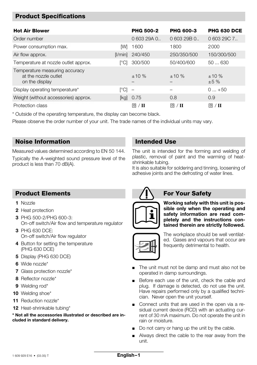
Product Specifications
| Hot Air Blower | PHG 500-2 | PHG 600-3 | PHG 630 DCE | |
| Order number | 0 603 29A 0.. | 0 603 29B 0.. | 0 603 29C 7.. | |
| Power consumption max. | [W] | 1600 | 1800 | 2000 |
| Air flow approx. | [I/min] | 240/450 | 250/350/500 | 150/300/500 |
| Temperature at nozzle outlet approx. | [°C] | 300/500 | 50/400/600 | 50 ... 630 |
| Temperature measuring accuracyat the nozzle outleton the display | ±10 % | ±10 % | ±10 % | |
| - | - | ±5 % | ||
| Display operating temperature* | [°C] | - | - | 0 ... +50 |
| Weight (without accessories) approx. | [kg] | 0.75 | 0.8 | 0.9 |
| Protection class | 回 / II | 回 / II | 回 / II | |
- Outside of the operating temperature, the display can become black.
Please observe the order number of your unit. The trade names of the individual units may vary.
Noise Information
Measured values determined according to EN 50 144.
Typically the A-weighted sound pressure level of the product is less than 70 dB(A).
Product Elements
1 Nozzle
2 Heat protection
3 PHG 500-2/PHG 600-3: On-off switch/Air flow and temperature regulator
3 PHG 630 DCE: On-off switch/Air flow regulator
4 Button for setting the temperature (PHG 630 DCE)
5 Display (PHG 630 DCE)
6 Wide nozzle
7 Glass protection nozzle
8 Reflector nozzle
9 Welding rod
10 Welding shoe
11 Reduction nozzle
12 Heat-shrinkable tubing*
- Not all the accessories illustrated or described are included in standard delivery.
Intended Use
The unit is intended for the forming and welding of plastic, removal of paint and the warming of heat-shrinkable tubing.
It is also suitable for soldering and tinning, loosening of adhesive joints and the defrosting of water lines.

For Your Safety
Working safely with this unit is possible only when the operating and safety information are read completely and the instructions contained therein are strictly followed.
The workplace should be well ventilated. Gases and vapours that occur are frequently detrimental to health.
- The unit must not be damp and must also not be operated in damp surroundings.
Before each use of the unit, check the cable and plug. If damage is detected, do not use the unit. Have repairs performed only by a qualified technician. Never open the unit yourself. -
Connect units that are used in the open via a residual current device (RCD) with an actuating current of 30mA maximum. Do not operate the unit in rain or moisture.
-
Do not carry or hang up the unit by the cable.
Always direct the cable to the rear away from the unit.
If the cable is damaged or cut through while working, do not touch the cable but immediately pull the mains plug. Never use the unit with a damaged cable.
- Do not operate the unit unattended.
During pauses in the work, when not in use or during work on the unit itself (e.g., changing of the working tools, repairs, cleaning, adjustment), pull the mains plug.
Wear safety glasses.
- The strong heating effect (e.g. as a result of careless handling) of this unit increases the danger of fire and explosion!
- When working with plastics, paints, lacquers and similar materials, combustible and poisonous gases can occur. Do not work in the vicinity of easily combustible gases or materials.
The heat can reach flammable parts that are located outside of the visible area.
- Do not point the unit for a long period at one spot.
Danger of burning! Do not touch the hot nozzle. Wear protective gloves.
- Never direct the air stream at persons or animals.
- Never use the unit as a hair dryer.
- Do not hold the nozzle outlet too close to the workpiece to be heated. The resulting restriction in the air flow can lead to overheating of the unit.
- Allow the unit to cool completely before storing. The hot nozzle can cause damage.
- Never allow children to use the unit.
- Bosch is able to ensure flawless functioning of the unit only if the original accessories intended for it are used.
Putting into Operation
Ensure that the mains voltage is correct!
The voltage of the power source must agree with the value given on the nameplate of the machine. Machines designated for 230V can also be operated with 220V .
Switching On/Off
Switching on:
PHG 500-2: To put into operation, slide the switch 3 to position I or II.
PHG 600-3, PHG 630 DCE: To put into operation, slide the switch 3 to position I, II or III.
Switching off:
To switch off, slide the on/off switch 3 to the stop at position 0.
PHG 600-3, PHG 630 DCE: After working for a longer time with high temperature, allow the unit to cool by running in the cold air setting I before switching off.
Thermo-Protection Switch-Off
When the heater is overloaded (e.g. as a result of restricted air flow), the unit switches it off automatically, however, the blower continues to run. When the unit has cooled to operating temperature, the heater is switched on again.
Setting the Air Flow and Temperature (PHG 500-2, PHG 600-3)
The switch 3 can be set to two (PHG 500-2) or three (PHG 600-3) blower steps. Suitable air flow and temperature combinations can be selected according to the applications.
| Step | PHG 500-2 | PHG 600-3 |
| I | 240 l/min, 300 °C | 250 l/min, 50 °C |
| II | 450 l/min, 500 °C | 350 l/min, 400 °C |
| III | - | 500 l/min, 600 °C |
PHG 600-3: The cold air setting I is suitable for cooling a warmed work piece or for the drying of paint. It is also suitable for cooling the unit before placing down or the changing of nozzles.
Setting the Air Flow (PHG 630 DCE)
The air flow can be set with the switch 3 in three steps. In steps II and III, the temperature can be regulated with the temperature button 4.
| Step | Air Flow | Temperature |
| I | 150 l/min | 50 °C |
| II | 300 l/min | 50 ... 630 °C |
| III | 500 l/min | 50 ... 630 °C |
Decrease the air flow when, for example:
The surroundings of the work piece should not be heated more than necessary
- A light work piece could be blown away by the air stream.
The cold air setting I is suitable for cooling a warmed work piece or for the drying of paint. It is also suitable for cooling the unit before placing down or the changing of nozzles.
Setting the Temperature (PHG 630 DCE)
In the blower steps II and III, the temperature can be continuously regulated.
After switching to the blower steps II or III, the temperature that was last selected as the target temperature appears in the display 5 marked with for approx. 3 second. The target temperature applies for both blower steps and does not change when switching between steps II and III.
After displaying the target temperature, the actual temperature at the nozzle outlet is shown with blinking until the selected target temperature is reached.
The arrows then disappear and the display 5 shows the actual temperature.
The target temperature can be increased in steps of 10^ by pressing the "+" side of the temperature button 4 or reduced by pressing the "--" side of the button 4. Brief pressing of the button increases or decreases the target temperature one time by 10^ . Longer pressing of the button increases or decreases the temperature continuously by 10^ steps until the button is released or the minimum or maximum temperature is reached.
In the blower step I, the pre-set temperature is 50^ . When switching from blower step II or III with higher temperatures to blower step I, a short time is required until the unit has cooled to 50^ . During the cooling period, the display 5 shows the actual temperature at the nozzle outlet.
Working Instructions
Removing the Heat Protector
For working in especially narrow places, the heat protector 2 can be removed.
- Be careful of the hot nozzle! Increased danger of burning exists when working without the heat protector.
To remove or mount the heat protector, the unit must be switched off and have cooled. For cooling, run briefly in the cold setting, if necessary.
Turn the heat protector 2 counter clockwise to remove and clockwise to mount again.
Placing Down the Unit
For cooling of the heated unit or to have both hands free for working, the unit can be place down in the upright position on the rear housing surface (see Fig. C).
- Be especially careful when working with the upright unit! There is danger of burning on the hot nozzle and the hot air stream.
Working Examples
The letters of the following application examples refer to the illustrations on the fold-out page.
Temperature settings given in the application examples are suggested values that, depending on the material characteristics, can deviate. The distance between the nozzle and workpiece is dependent on the material to be processed.
The ideal temperature should first be ascertained by performing a test. Therefore, begin with a lower temperature setting.
All application examples (except E ) can be performed without accessories. However, the use of the recommended accessory parts simplify the work and significantly improve the quality of the results.
- Be careful when changing the nozzle, danger of burning! Do not tough the hot nozzle. Allow the unit to cool. Wear protective gloves.
Bosch stocks an extensive range of accessories (see Bosch Accessories catalogue) which offer a wide range of other applications.
Additional information can be found in popular DIY books.
A Removing paint/softening adhesives
Place on the wide nozzle 6. Soften the paint using hot air and remove evenly using a spatula. Do not heat the paint for too long since this will burn the paint, making it more difficult to remove.
Many adhesives (e.g. stickers) become softer when heated allowing adhesive bonds to be separated or superfluous adhesive to be removed.
Removing paint from window frames Danger of glass breaking!
Use of the glass protection nozzle 7 is essential. On profiled surfaces, paint can be removed using a spatula and brushed off using a soft wire brush.
C Shaping plastic tubing
Place on the reflector nozzle 8. To avoid kinking the tubing, fill the tubing with sand and seal at both ends. Heat the tubing evenly by moving it from side to side.
D Welding plastics
Place on the reduction nozzle 11 and the welding shoe 10. The materials to be welded and the welding rod 9 must be made of the same material (e.g. PVC with PVC). The seam must be clean and grease-free.
Heat the welding seam until it becomes tacky. Please note that the temperature difference between the tacky and liquid state of a plastic is very small. Then feed in the welding rod 9 and allow to run into the gap so that a uniform bead is produced.
E Shrink fitting
Place on the reduction nozzle 11. Select the diameter of the heat-shrink tubing 12 according to the work piece, for example, a cable lug.
Heat the heat-shrinkable sleeve evenly.
F Defrosting water pipes

Water lines often do not differ in appearance from gas lines. Gas lines are not to be heated under any circumstances.
Place on the reflector nozzle 8. Heat the frozen zone always from the outside to the middle.
Warm plastic pipes as well as connections between pipe pieces especially carefully to prevent damage.

Soft Soldering
For point soldering, place on the reduction nozzle 11, for the soldering of pipes, the reflector nozzle 8. If solder without flux is used, apply soldering grease or paste to the location to be soldered. Warm the location to be soldered for 50 - 120s depending on the material. Apply the solder. The solder must melt from the work piece temperature. After the soldered location has cooled, remove the flux.
Maintenance and Cleaning
Before any work on the unit itself, pull the mains plug.
For safe and efficient working, always keep the unit and the ventilation slots clean.
WARNING
Important instructions for connecting a new 3-pin plug to the 2-wire cable.
The wires in the cable are coloured according to the following code:
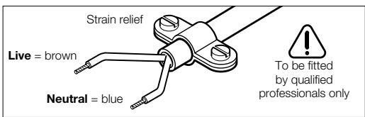
Do not connect the blue or brown wire to the earth terminal of the plug.
Important: If the plug on the cable of this unit must be replaced, dispose of the old plug to prevent misuse.
If the unit should fail despite the care taken in manufacture and testing, repair should be carried out by an authorised customer services agent for Bosch power tools.
For all correspondence and spare parts orders, always include the 10-digit order number of the unit.
Environmental Protection

Recycle raw materials instead of disposing as waste.
The unit, accessories and packaging should be submitted for environment-friendlyly recycling.
These instructions are printed on recycled paper manufactured without chlorine.
The plastic components are labelled for categorised recycling.
Service and Customer Advice
Great Britain
Robert Bosch Ltd. (B.S.C.)
P.O.Box 98
Broadwater Park
North Orbital Road
Denham-Uxbridge
MIDDLEX UB 9 5HJ
Service +44 (0) 18 95/83 87 82
Advice line. +44 (0) 18 95/83 87 91
Fax +44 (0) 18 95/83 87 89
Ireland
Beaver Distribution Ltd.
Greenhills Road
Tallaght-Dublin 24
Service +353 (0)1/414 9400
Fax 353 (0)1/459 8030
Australia
Robert Bosch Australia L.t.d.
RBAU/SBT2
1555 Centre Road
P.O. Box 66 Clayton
3168 Clayton/Victoria
+61 (0)1/800 804 777
Fax .+61 (0)1/800 819 520
www.bosch.com.au
E-Mail: CustomerSupportSPT@au.bosch.com
New Zealand
Robert Bosch Limited
14-16 Constellation Drive
Mairangi Bay
Auckland
New Zealand
+64 (0)9/47 86 158
Fax +64 (0)9/47 82 914

Declaration of Conformity
We declare under our sole responsibility that this product is in conformity with the following standards or standardization documents:
EN 60 335 according to the provisions of the directives 73/23/EEC, 89/336/EEC.
03
Dr. Egbert Schneider
Senior Vice President
Engineering
Dr. Eckerhard Strötgen
Head of Product
Certification


Specification subject to alteration without notice
\section*{Caracteristiques techniques}
Robert Bosch France S.A.
Service Avres-vente Outilage
Senior Vice President
Engineering
Dr. Eckerhard Strötgen
Head of Product
Certification


Senior Vice President
Engineering
Dr. Eckerhard Strötgen
Head of Product
Certification

A Remover verniz/solver cola
Senior Vice President
Engineering
Dr. Eckerhard Strötgen
Head of Product
Certification

Dr. Egbert Schneider Senior Vice President Engineering
Dr. Eckerhard Strötgen
Head of Product Certification


Senior Vice President
Engineering
Dr. Eckerhard Strötgen
Head of Product
Certification

Dr. Egbert Schneider Senior Vice President Engineering
Dr. Eckerhard Strötgen
Head of Product Certification
ppa. Maee i.v. nye
Senior Vice President
Engineering
Dr. Eckerhard Strötgen
Head of Product
Certification

Senior Vice President
Engineering
Dr. Eckerhard Strötgen
Head of Product
Certification


Dr. Egbert Schneider Senior Vice President Engineering
Dr. Eckerhard Strötgen
Head of Product Certification
ppa. Maee i.v. n
Xpouoio Tc onooohno to akpoouo npootaia yuaaiou 7.
Navw o avwaac e nipavee to bpvki mnpoei va anopakpuvtheta i ne tv kataaan onatoula kai va Bouptoitheta i maakoupaotota.
C Inapapoppwon nlaotikw oawlvw
TOnoTheTeToakpOuio avaklaonc8.1a va eunobioe i eva Luyiaota Tou oWlnva, npentie va yei amu kai va Bouw0ei kai ano tic duo nLupec. Eepaivte OoiOppa Tov oWlnva u naIbopouikk ivnon npoc ta nnayia.
D Suykokaionn nlaotikwv
TOno8eTeToakpoFuaio ouToaNc11kai to
P6dilo ouyKoAaonC 10.Ta npoc ouyKoAaon
Teuaxia kai to oupa ThepoooukyKaONC9
npenei va eiva ano To iDIO uAIKO (n.x.
NoIauBivUaoXawipioe noLuBivUaoXawipio).H
Papn pEnei va eiva kaOapn kai aNaalayEvn
anO limn.
to o nueio nou npoketai va ouykoalnoe tex p1 aonktne 1aatakn mopn. Pooexte, wote n diaopa theoepuokpaia cetau tn noatowous kai ts ncs peuotnc kataotaoc v eivai elaxiotn. Eiaayete to oupma oukykolnonc 9 oto neilao uoykollnonc ki apnte to va ,tpeei" kata teio io tropo ot onxiaumva xnuatotie ia ooiopopn onepia.
E SuppiKvwoJ
TootheTto akpofoio ourolo 11. EiAeTe Tn diatou n Tou eepouoppkvou evou v a 12 avalo y e to uno katepyaia teuaxio, n.x. to nediO kaawdiou.
i t a l o o l o a tov Eukamto 0eP OoouppikvouEvo oWlna.
F Eπaywμa uδρωωληvω

Euva, oUbpOoawInevEc δe diaqepouv EεwTepiKa ano touc owInevC φwTaepiou [ykaizou]. AnayopEuEaTn θεpμavon Tov wIhVW φwTaepiou.
TootheTto akpoquo avakkaan8.
OepaivTe to naywuevo aneio ano ,ta Ew npoc ta eoa".
IIaotikoi oawlvcKaohcKai ouvdeoeic eTaEoawlv npenei va eepaivovtai pooekrtika yia v anopeuxtouv tuxov zneic.
G SuykoAaonn e Kaai
Tia tn ouykoAon mEvovwEwv onuEiw tootheTote to akpopuio auotolns 11, ia tn ouykokAon oWlvwTooTheTote to akpopuio avakkaons 8.
Av xpnoionoieite kaai xwpioc oukykOaNtiko uypo [oullinaogma] aaleiye Tnv m e iinoc n aoata ouykOaNOnc. 0epaavte Tnv uno ouykoAonn o5-120 s npinou, avaloya e To avitioxu uikno. Ppooeote to kai.To kaai npetie va luwoei ano tn 0epukpaia tou uno katepyaia temuaxiou.
ApaipoeTo ouykoanTiko Uypo oaiKpuooEi npaqn.
Senior Vice President
Engineering
Dr. Eckerhard Strötgen
Head of Product
Certification


Emuaooepa yia tuxov aalayes
Teknik veriler
Bosch San. ve Tic. A.S.
Ahi Evran Cad. No:1 Kat:22
Polaris Plaza
80670 Maslak/Istanbul
C .+90 (0)212/335 06 00
Faks .+90 (0)212/346 00 48-49
Uygunluk beyani
Senior Vice President
Engineering
Dr. Eckerhard Strötgen
Head of Product
Certification
ppa. Maee i.v. Hye


- Schweiz
- Product Specifications
- Noise Information
- Product Elements
- Intended Use
- For Your Safety
- Putting into Operation
- Ensure that the mains voltage is correct!
- Switching On/Off
- Switching on:
- Switching off:
- Thermo-Protection Switch-Off
- Setting the Air Flow and Temperature (PHG 500-2, PHG 600-3)
- Setting the Air Flow (PHG 630 DCE)
- Setting the Temperature (PHG 630 DCE)
- Working Instructions
- Removing the Heat Protector
- Placing Down the Unit
- Working Examples
- A Removing paint/softening adhesives
- Removing paint from window frames Danger of glass breaking!
- C Shaping plastic tubing
- D Welding plastics
- E Shrink fitting
- F Defrosting water pipes
- Soft Soldering
- Maintenance and Cleaning
- WARNING
- Important instructions for connecting a new 3-pin plug to the 2-wire cable.
- Environmental Protection
- Recycle raw materials instead of disposing as waste.
- Service and Customer Advice
- Great Britain
- Ireland
- Australia
- New Zealand
- Declaration of Conformity
- \section*{Caracteristiques techniques}
- A Remover verniz/solver cola
- C Inapapoppwon nlaotikw oawlvw
- D Suykokaionn nlaotikwv
- E SuppiKvwoJ
- F Eπaywμa uδρωωληvω
- G SuykoAaonn e Kaai
- Teknik veriler
- Uygunluk beyani
Brand : BOSCH
Model : PHG 600-3
Category : Hair dryer