
PDO 6 - Gas detector BOSCH - Free user manual and instructions
Find the device manual for free PDO 6 BOSCH in PDF.
| Brand | BOSCH |
| Model | PDO 6 |
| Category | Gas detector |
| Detection type | Ferrous metals, non-ferrous metals, live wires (110-400 V AC) |
| Max. detection depth ferrous metals | 60 mm |
| Max. detection depth non-ferrous metals (copper) | 50 mm |
| Max. detection depth live wires | 30 mm |
| Power supply | 1 9V 6LR61 battery or 9V 6F22 rechargeable battery |
| Battery life (alkaline) | Approximately 6 hours |
| Automatic shutdown | After approximately 10 minutes without measurement |
| Operating temperature | -10 °C to +50 °C |
| Storage temperature | -20 °C to +70 °C |
| Weight (according to EPTA 01/2003) | 0.2 kg |
| Display | Display with charge indicator, metal detection, voltage, AutoCal calibration |
| Signaling | Green/red light ring and audible signal |
| Object marking | Marking opening for pencil |
| Maintenance | Clean with a soft, dry cloth; do not use solvents |
| Manual calibration | Possible in case of permanent fluctuations |
| Article number | 3 603 K10 100 |
| After-sales service France | 01 43 11 90 06 / 0 800 05 50 51 |
Frequently Asked Questions - PDO 6 BOSCH
User questions about PDO 6 BOSCH
0 question about this device. Answer the ones you know or ask your own.
Ask a new question about this device
Download the instructions for your Gas detector in PDF format for free! Find your manual PDO 6 - BOSCH and take your electronic device back in hand. On this page are published all the documents necessary for the use of your device. PDO 6 by BOSCH.
USER MANUAL PDO 6 BOSCH
natural_image
Illustration of a Bosch PDO 6 digital camera with control panel and display (no text or symbols on device body)
Deutsch
English
Français
Español
Português
Italiano
Nederlands
Dansk
Svenska
Norsk
Suomi
Ελληνικά
Türkçe


natural_image
Top-down diagram of a vehicle with directional arrows indicating movement or force (no text or symbols)© Service +43 (0)1/61 03 80
Fax....+43 (0)1/61 03 84 91
© Kundenberater .....+43 (0)1/7 97 22 30 66
E-Mail: abe@abe-service.co.at
Schweiz
① 0 44/8 47 15 11
Fax 0 44/8 47 15 51
Luxemburg
① +32 (0)70/22 55 65
Fax....+32 (0)70/22 55 75
E-Mail: outillage.gereedschap@be.bosch.com

10 | Deutsch
natural_image
Symbol of a trash bin crossed out by two crossed lines, enclosed in a rounded square (no text or numbers present)Functional Description

Optimal working with the measuring tool is possible only when the operating instructions and information are read completely, and the instructions contained therein are strictly followed. SAVE THESE INSTRUCTIONS.
Intended Use
The measuring tool is intended for the detection of metals (ferrous and non-ferrous metals, e.g., rebar) and “live” wires/conductors in walls, ceilings and floors.
Product Features
The numbering of the product features shown refers to the illustration of the measuring tool on the graphic page.
1 Illuminated ring
2 Marking hole
3 Display
4 On/Off button
5 Sensor area
6 Battery lid
7 Latch of battery lid
Display Elements
a Battery indication
b "Live" wire indicator
c Measuring indicator
d "AutoCal" calibration indicator


12 | English
| Digital Detector | PDO 6 |
| Article number | 3 603 K10 100 |
| Maximum scanning depth*: | |
| - Ferrous metals | 60 mm |
| - Non-ferrous metals (copper pipe) | 50 mm |
| - Copper conductors (live)** | 30 mm |
| Automatic switch-off after approx. | 10 min |
| Operating temperature | -10 ^...+50 ^ |
| Storage temperature | -20 ^...+70 ^ |
| Battery | 1 x 9 V 6LR61 |
| Rechargeable battery | 1 x 9 V 6F22 |
| Operating lifetime(alkali-manganese batteries) approx. | 6 h |
| Weight according toEPTA-Procedure 01/2003 | 0.2 kg |
* depends on material and size of objects as well as material and condition of structure
** less scanning depth for wires/conductors that are not "live"
Please observe the article number on the type plate of your measuring tool. The trade names of the individual measuring tools may vary.
Assembly
Inserting/Replacing the Battery
Use only alkali-manganese or rechargeable batteries.
To open the battery lid 6, press the latch 7 in the direction of the arrow and fold the battery lid downward. Insert the battery provided. Pay attention that the polarity is correct.

When the battery indication a in the display lights up, measuring is possible for approx. 1 h when using alkali-manganese batteries (service life is shorter with rechargeable batteries). When the battery indication a flashes, measuring is still possible for approx. 10 minutes. When the battery indication a and the illuminated ring 1 (red) are flashing, measuring is no longer possible and the battery or the rechargeable battery respectively, must be replaced.
▶ If the measuring tool is not used for a long period of time, the battery must be removed. The battery can corrode or discharge itself over long periods.
Operation
Initial Operation
▶ Protect the measuring tool against moisture and direct sun irradiation.
Switching On and Off
▶ Before switching the measuring tool on, make sure that the sensor area 5 is not moist. If required, wipe the measuring tool dry using a cloth.
▶ If the measuring tool was subject to an extreme temperature change, allow it to adjust to the ambient temperature before switching on.
To switch on the measuring tool, press the On/Off switch 4.
After a brief self-check, the measuring tool is ready for operation. The operational readiness is indicated by a check mark behind the "AutoCal" calibration indicator d.
To switch the measuring tool off, press the "on/off" button 4.
When no measurements are carried out for approx. 10 minutes, the measuring tool switches off automatically in order to extend the service life of the batteries.


Operating Modes
The measuring tool detects objects below the sensor area 5.
Detecting Metal Objects
After switching on, the illuminated ring 1 lights up green.
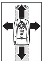
natural_image
Top-down diagram of a vehicle with directional arrows indicating movement or force (no text or symbols)Place the measuring tool on the surface to be scanned and move it sidewards. When the illuminated ring 1 continues to light up green and no signal tone sounds, then no metal object is detectable in the structural material below. When the measuring tool comes close to a metal object, the amplitude in the measuring indicator c increases. When the measuring tool is above a metal object, the ring 1 turns red and a signal tone sounds.
When moving over a surface the first time, the position of the metal object is indicated only approximately. When moving the measuring tool over the metal object several times, the object is detected more and more precisely. After moving over the surface above the metal object several times (without lifting off the measuring tool from the surface), the position of the metal object can be indicated accurately: When the illuminated ring 1 lights up red and the signal tone sounds, then the metal object is below the centre of the sensor (below the marking hole 2).
Scanning for "Live" Wires
The measuring tool indicates “live” wires/conductors that carry voltages between 110 V and 400 V, and a frequency corresponding with the common standard (AC with 50 to 60 Hz). Other wires/conductors (carrying DC, higher/lower frequency or voltage) as well as “dead” wires/conductors cannot be found reliably, but are possibly indicated as metal objects.
The scan for “live” wires/conductors takes place automatically for each measurement. When a “live” wire/conductor is detected, the indicator b appears in the display. Move the measuring tool over the surface repeatedly in order to localise the “live” wire. After moving the measuring tool over the surface several times, the position of the “live” wire/conductor can be indicated quite precisely. If the measuring tool is very close to the wire/conductor, then the illuminated ring 1 lights up red and the signal tone sounds with rapid tone sequence.


“Live” wires/conductors can be detected easier when power consumers (e.g., lamps, appliances) are connected to the wire/conductor being sought and switched on. Wires/conductors with 110 V, 230 V and 400 V (three-phase current) are detected with about the same scan capacity.
Under certain conditions (such as when behind metal surfaces or behind surfaces with high water content), “live” wires/conductors cannot be detected with certainty. When measuring indicator c is indicated over a larger range, then the material is screening-off electrically and the scan for “live” wires/conductors is not reliable.
Operating Instructions
On condition of the principle, the measuring values can be impaired through certain ambient conditions. These include, e.g., the proximity of other equipment that produce strong magnetic or electromagnetic fields, moisture, metallic building materials, foil-laminated insulation materials or conductive wallpaper. Therefore, please also observe other information sources (e.g. construction plans) before drilling, sawing or routing into walls, ceilings or floors.
Marking Objects
Detected objects can be marked as required. Where the amplitude of measuring indication c is at its maximum, the centre of the object is located below marking hole 2. The limits of an object are indicated by the colour change of the illuminated ring 1 from green to red. Using a pen, mark the sought after location through the marking hole 2.
"AutoCal" Calibration Indicator
When the check mark behind the “AutoCal” calibration indicator d flashes for longer periods or if it is not displayed anymore, reliable scanning is no longer possible. In this case, send in the measuring tool to an authorised Bosch after-sales service agent.

Maintenance and Service
Maintenance and Cleaning
When the measuring indicator c continuously shows an amplitude even though there is no metal object in the vicinity of the measuring tool, the measuring tool can be calibrated manually. For this, remove all objects in the vicinity of the measuring tool (including wrist watches or rings of metal) and hold the measuring tool up in the air. With the measuring tool switched off, press the On/Off button 4 until the illuminated ring 1 lights up red and green at the same time. Then release the button. When the calibration process was successful, the measuring tool will start over after a few seconds and is then ready for operation.
Wipe away debris or contamination with a dry, soft cloth. Do not use cleaning agents or solvents.
In order not to affect the measuring function, decals/stickers or name plates, especially metal ones, may not be attached in the sensor area 5 on the front or back side of the measuring tool.
If the measuring tool should fail despite the care taken in manufacturing and testing procedures, repair should be carried out by an authorized after-sales service centre for Bosch power tools.
In all correspondence and spare parts orders, please always include the 10-digit article number given on the type plate of the measuring tool.

Service and Customer Assistance
Exploded views and information on spare parts can be found under: www.bosch-pt.com
Great Britain
Robert Bosch Ltd. (B.S.C.)
P.O. Box 98
Broadwater Park
North Orbital Road
Denham-Uxbridge
Middlesex UB 9 5HJ
© Service: +44 (0) 18 95 / 83 87 82
© Advice line: +44 (0) 18 95 / 83 87 91
Fax:....+44 (0) 18 95 / 83 87 89
Ireland
Origo Ltd.
Unit 23 Magna Drive
Magna Business Park
City West
Dublin 24
© Service:....+353 (0)1 / 4 66 67 00
Fax:....+353 (0)1 / 4 66 68 88
Australia and New Zealand
Robert Bosch Australia Pty. Ltd.
RBAU/SPT
1555 Centre Road
P.O. Box 66
3168 Clayton/Victoria
① +61 (0)1 / 3 00 30 70 44
Fax:....+61 (0)1 / 3 00 30 70 45
www.bosch.com.au


18 | English
Measuring tools, accessories and packaging should be sorted for environmental-friendly recycling.
Only for EC countries:
natural_image
Symbol of a trash bin crossed out by two crossed lines, enclosed in a rounded square (no text or numbers present)Do not dispose of measuring tools into household waste!
According to the European Guideline 2002/96/EC for Waste Electrical and Electronic Equipment and its implementation into national right, measuring tools that are no longer usable must be collected separately and disposed of in an environmentally correct manner.
Battery packs/batteries:
Do not dispose of battery packs/batteries into household waste, fire or water. Battery packs/batteries should be collected, recycled or disposed of in an environmental-friendly manner.
Only for EC countries:
Defective or dead out battery packs/batteries must be recycled according the guideline 91/157/EEC.
Batteries no longer suitable for use can be directly returned at:
Great Britain
Robert Bosch Ltd. (B.S.C.)
P.O. Box 98
Broadwater Park
North Orbital Road
Denham-Uxbridge
Middlesex UB 9 5HJ
© Service: +44 (0) 18 95 / 83 87 82
© Advice line: ..... +44 (0) 18 95 / 83 87 91
Fax:....+44 (0) 18 95 / 83 87 89
Subject to change without notice.


natural_image
Top-down diagram of a vehicle with directional arrows indicating movement or force (no text or symbols)Robert Bosch France S.A.S.
Service Après-vente/Outillage
natural_image
Symbol of a trash bin crossed out by two crossed lines, enclosed in a rounded square (no text or numbers present)natural_image
Top-down diagram of a vehicle with directional arrows indicating movement or force (no text or symbols)natural_image
Symbol of a trash bin crossed out by two crossed lines, enclosed in a rounded square (no text or numbers present)natural_image
Top-down diagram of a vehicle with directional arrows indicating movement or force (no text or symbols)natural_image
Symbol of a trash bin crossed out by two crossed lines, enclosed in a rounded square (no text or numbers present)natural_image
Top-down diagram of a car with directional arrows indicating movement or force (no text or symbols)natural_image
Symbol of a trash bin crossed out by two crossed lines, enclosed in a rounded square (no text or numbers present)natural_image
Top-down diagram of a vehicle with directional arrows indicating movement or force (no text or symbols)natural_image
Symbol of a trash bin crossed out by two crossed lines, enclosed in a rounded square (no text or numbers present)natural_image
Top-down diagram of a vehicle with directional arrows indicating movement or force (no text or symbols)natural_image
Symbol of a trash bin crossed out by two crossed lines, enclosed in a rounded square (no text or numbers present)natural_image
Top-down diagram of a vehicle with directional arrows indicating movement or force (no text or symbols)natural_image
Symbol of a trash bin crossed out by two crossed lines, enclosed in a rounded square (no text or numbers present)natural_image
Top-down diagram of a vehicle with directional arrows indicating movement or force (no text or symbols)natural_image
Symbol of a trash bin crossed out by two crossed lines, enclosed in a rounded square (no text or numbers present)natural_image
Top-down diagram of a vehicle with directional arrows indicating movement or force (no text or symbols)natural_image
Symbol of a trash bin crossed out by two crossed lines, enclosed in a rounded square (no text or numbers present)natural_image
Top-down diagram of a vehicle with directional arrows indicating movement or force (no text or symbols)© +30 21 05 70 12 00 KENTPO
© +30 21 05 77 00 81 - 83 KENTPO
Fax:....+30 21 05 70 12 63
Fax:....+30 21 05 77 00 80
www.bosch.gr
ABZ Service A.E.
© +30 2 10 57 01 375 - 378 SERVICE
Fax:....+30 21 05 77 36 07
Απόσυρση
natural_image
Symbol of a trash bin crossed out by two crossed lines, enclosed in a rounded square (no text or numbers present)natural_image
Top-down diagram of a vehicle with directional arrows indicating movement or force (no text or symbols)Bosch San. ve Tic. A.S.
Ahi Evran Cad. No:1 Kat:22
Polaris Plaza
80670 Maslak/Istanbul
natural_image
Symbol of a trash bin crossed out by two crossed lines, enclosed in a rounded square (no text or numbers present)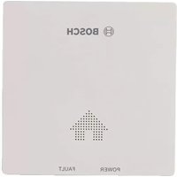
- Schweiz
- Luxemburg
- Functional Description
- Intended Use
- Product Features
- Display Elements
- Assembly
- Inserting/Replacing the Battery
- Operation
- Initial Operation
- Switching On and Off
- Operating Modes
- Detecting Metal Objects
- Scanning for "Live" Wires
- Operating Instructions
- Marking Objects
- "AutoCal" Calibration Indicator
- Maintenance and Service
- Maintenance and Cleaning
- Service and Customer Assistance
- Great Britain
- Ireland
- Australia and New Zealand
- Only for EC countries:
- Battery packs/batteries:
- Απόσυρση
Brand : BOSCH
Model : PDO 6
Category : Gas detector