USER MANUAL PWS 9-125 CE BOSCH
Operating instructions
natural_image
Illustration of a Bosch angle grinder with visible brand label (no text or symbols beyond branding)

flowchart
graph TD
    A["Professional plus"] --> B["Professional"]
    B --> C["professional eco"]
    C --> D["professional"]
    D --> E["professional RAPIDO"]
    F["Professional"] --> G["blue:Metal top"]
    F --> H["blue:Metal"]
    I["professional"] --> J["blue:Metal top"]
    I --> K["blue:Metal"]

Gerätekennwerte
natural_image
Illustration of a robotic arm operating on a rotating platform with motion arrows (no text or symbols)
natural_image
Diagram of a pipe valve with rotating components and directional arrows indicating flow (no text or symbols)
Senior Vice President
Engineering
Dr. Eckerhard Strötgen
Head of Product
Certification

i.v. Moyen
Please observe the order number of your machine. The trade names of the individual machines may vary.
* The values given are valid for nominal voltages [U] of 230/240 V. For lower voltages and models for specific countries, these values can vary.
Speed Preselection (Type CE)
| Material | Application | Tool | Thumbwheel |
| Plastic | Polishing | Lamb’s wool hood | 1 |
| Finish polishing | Felt polishing disk | 1 |
| Metal | Finish grinding | Buffing disk | 1 |
| Removing paint | Sanding sheet | 2–3 |
| Wood, Metal | Brushing, Removing rust | Cup brush, sanding sheet | 3 |
| Metal, Stone | Grinding | Grinding disk | 4–6 |
| Metal | Roughing | Roughing disk | 6 |
| Stone* | Cutting* | Cutting disk and cutting guide | 6 |
* Cutting of stone is permitted only with the cutting guide (accessory).
Intended Use
The machine is intended for cutting, roughing and brushing metal and stone materials without using water. For cutting stone, a cutting guide is required.
For machines with electronic control: With approved sanding tools, the machine can be used for sanding and polishing.
Measured values determined according to EN 50 144.
Typically the A-weighted noise levels of the product are: sound pressure level: 88 dB (A); sound power level: 101 dB (A).
Wear hearing protection!
The typically weighted acceleration is 5.0 m/s^2 .
When using the vibration-dampening auxiliary handle, the hand-arm vibration at the auxiliary handle is typically below 2.5 m/s^2 .
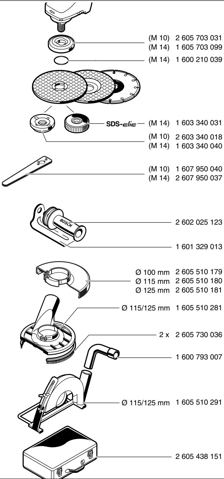
Machine Elements
1 On/Off switch
2 Thumbwheel for speed preselection (PWS 8-125 CE/PWS 850 CE/PWS 9-125 CE)
3 Auxiliary handle
4 Spindle lock button
5 Grinder spindle
6 Protection guard
7 Clamping lever
8 Mounting flange (for the M 14 grinding spindle with O-ring)
9 Grinding/cutting disc*
10 Clamping nut
11 SDS-elic quick-clamping nut (for M 14 grinder spindle)*
12 Hand guard*
13 Rubber sanding pad*
14 Sanding sheet*
15 Round nut*
16 Cup brush*
17 Cutting guide with dust extraction protection guard*
18 Diamond cutting disc*
19 Mounting flange M 10
* Not all of the accessories illustrated or described are included as standard delivery.

For Your Safety

Working safely with this machine is possible only when the operating and safety information are read completely and the instructions contained therein are strictly followed. In addition, the general safety notes in the enclosed booklet must be observed. Before using for the first time, ask for a practical demonstration.
■ Wear protective glasses and hearing protection.
■ Wear additional protection equipment for your safety, such as protective gloves, sturdy shoes, hard hat and apron.
■ The dust that is produced while working can be detrimental to health, inflammable or explosive. Suitable safety measures are required.
Examples: Some dusts are regarded as carcinogenic. Use suitable dust/chip extraction and wear a dust respirator.
■ Dust from light alloys can burn or explode. Always keep the workplace clean, as blends of materials are particularly dangerous.
If the mains cable is damaged or cut through while working, do not touch the cable but immediately pull the mains plug. Never use the machine with a damaged cable.
■ Connect machines that are used in the open via a residual current device (RCD) with an actuating current of 30 mA maximum. Do not operate the machine in rain or moisture.
■ When working with the machine, always hold it firmly with both hands and provide for a secure stance.
- Secure the workpiece. A workpiece clamped with clamping devices or in a vice is held more secure than by hand.
■ Always direct the cable to the rear away from the machine.
■ Always switch the machine off and wait until it has come to a standstill before placing it down.
For power outage or when the mains plug is pulled, unlock the On/Off switch immediately and turn it to the off position. This prevents uncontrolled restarting.
■ The machine must be used only for dry cutting/grinding.
■ For all work with the machine, the auxiliary handle 3 must be mounted.
■ Hold the power tool only by the insulated gripping surfaces, when performing an operation where the cutting tool may run into hidden wiring or its own cord.
Contact with a “live” wire will make exposed metal parts of the tool “live” and shock the operator.
■ Use appropriate detectors to determine if utility lines are hidden in the work area or call the local utility company for assistance.
Contact with electric lines can lead to fire and electric shock. Damaging a gas line can lead to explosion. Penetrating a water line causes property damage or may cause an electric shock.
For work with grinding or cutting discs, the protection guard 6 must be mounted. For work with the rubber sanding pad 13 or with the cup brush 16/disc brush/flap disc, mounting the hand guard 12 (accessory) is recommended.
■ Use dust extraction when working with stone. The vacuum cleaner must be approved for masonry dust. When cutting stone, use the cutting guide.
■ Do not work with materials containing asbestos.
■ Use only grinding tools with a permissible speed at least as high as the no-load speed of the machine.
■ Check grinding tools before use. The grinding tool must be properly mounted and turn freely. Perform a test run for at least 30 seconds without load. Do not use damaged, out-of-round or vibrating grinding tools.
■ Protect the grinding tool from impact, shock and grease.
■ Apply the machine to the workpiece only when switched on.
- Keep hands away from rotating grinding tools.
■ Pay attention to the direction of rotation. Always hold the machine so that sparks and grinding dust fly away from the body.
■ When grinding metal, flying sparks are produced. Take care that no persons are endangered. Due to danger of fire, no combustible materials should be located in the vicinity (spark flight zone).
■ Be careful when cutting grooves, e. g. in structural walls: See Information on Structures.
■ Blocking the cutting disc leads to jerking reaction forces on the machine. In this case switch off the machine immediately.
■ Observe the dimensions of the grinding discs. The hole diameter must fit mounting flange 8 (M 14), 19 (M 10). Do not use any reducers or adapters.
■ Never use cutting discs for rough grinding. Do not exert any lateral pressure on the cutting discs.
- Observe the manufacturer's instructions for mounting and using grinding tools.
■ Caution! The grinding tool runs on after the machine is switched off.
■ Do not clamp the machine in a vice.
■ Never allow children to use the machine.
■ Bosch is only able to ensure perfect operation of the machine if the original accessories intended for it are used.
Slots in structural walls are subject to the Standard DIN 1053, Part 1 or country-specific regulations.
These regulations are to be observed under all circumstances. Before beginning work, consult the responsible structural engineer, architects or the construction supervisor.

Mounting the Protective Devices
■ Before any work on the machine itself, pull the mains plug.
Protection Guard
■ For work with grinding or cutting discs, the protection guard 6 must be mounted.
Open the clamping lever 7.
Place the protection guard 6 onto the spindle collar of the machine head as shown in the illustration. The encoding keys of the protection guard must match with the respective recesses on the spindle collar.
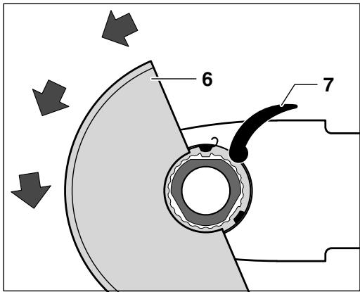
Press the protection guard onto the spindle collar until the collar of the protection guard faces against the flange of the machine and the encoding keys engage in the circular groove at the spindle collar.
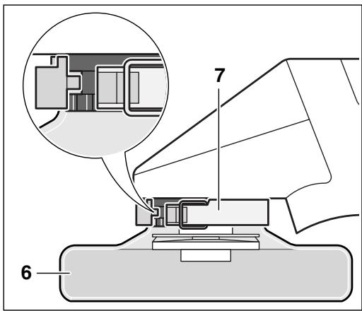
Rotate the protection guard 6 in clockwise direction to the required position (working position).
Adjust the protection guard 6 in such a manner that sparks are not emitted in the direction of the operator.
Note: Encoding keys on the protection guard 6 ensure that only a protection guard that fits the machine type can be mounted.
Disassemble in the reverse sequence.
Auxiliary Handle
■ For all work with the machine, the auxiliary handle 3 must be mounted.
Screw the auxiliary handle 3 on the right or left of the machine head depending on the working method.
Vibration-dampening Auxiliary Handle
VIBRATION CONTROL
The vibration-dampening auxiliary handle reduces the vibrations, making operation more comfortable and secure.

Do not make any alterations to the auxiliary handle.
Do not continue to use an auxiliary handle if it is damaged.
Hand Guard
For work with the rubber sanding pad 13 or with the cup brush 16/disc brush/flap disc, mounting the hand guard 12 (accessory) is recommended. The hand guard 12 is fastened with the auxiliary handle 3.
■ Before any work on the machine itself, pull the mains plug.

Use only grinding tools with a permissible speed at least as high as the no-load speed of the machine.
Grinding and cutting discs become very hot while working; do not touch until they have cooled.
■ Clean the grinder spindle and all parts to be mounted. For clamping and loosening the grinding tools, lock the grinder spindle 5 with the spindle lock button 4.
Actuate the spindle lock button 4 only when the grinder spindle is at a standstill!
Grinding/Cutting Disc
Observe the dimensions of the grinding discs. The hole diameter must fit mounting flange 8 (M 14), 19 (M 10). Do not use any reducers or adapters.
When using a diamond cutting disc, take care that the direction-of-rotation arrow on the diamond cutting disc and the direction of rotation of the machine (direction-of-rotation arrow on the machine head) agree.
For mounting, see the illustration page.
Screw on the clamping nut 10 and tighten with the two-pin spanner (see Section "Quick-clamping Nut").
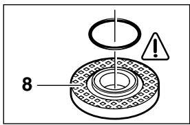
Mounting flange for grinding spindle M 14
An O-ring (plastic part) is inserted in the mounting flange 8 around the spigot.
If the O-ring is missing or is damaged, it must in all cases be replaced (Order No. 1 600 210 039) before the mounting flange 8 is mounted.
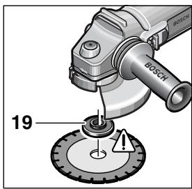
Mounting flange for grinding spindle M 10
The mounting flange 19 can be used on both sides. For diamond cutting discs it must be positioned on the grinding spindle 5 and turned through 180°.
The bore of the diamond cutting disc (∅ 20 mm) must fit the spigot of the mounting flange 19 without any play.
Do not use any reducers or adapters.

After mounting the grinding tool and before switching on, check that the grinding tool is correctly mounted and that it can turn freely.
Flap Disc
(for M 14 grinder spindle)
Depending on the application, remove the protection guard 6 and mount the hand guard 12. Place the special mounting flange 8 (accessory, Order No. 2 605 703 028) and the flap disc on the grinder spindle 5. Screw on the clamping nut 10 and tighten with the two-pin spanner.
Rubber Sanding Pad 13
Depending on the application, remove the protection guard 6 and mount the hand guard 12.
For mounting, see the illustration page.
Screw on the round nut 15 and tighten with the two-pin spanner.
Cup Brush 16/Disc Brush
(for M 14 grinder spindle)
Depending on the application, remove the protection guard 6 and mount the hand guard 12.
The grinding tool must be able to be screwed onto the grinding spindle 5 until it rests firmly against the grinder spindle flange at the end of the grinder spindle threads. Tighten with an open-end spanner.
Quick Clamping Nut SDS-clic
(for M 14 grinder spindle)
Instead of the clamping nut 10, the quick-clamping nut 11 (accessory) can be used. Grinding tools can then be mounted without using tools.
The quick-clamping nut 11 may be used only for grinding and cutting discs.
Use only a flawless, undamaged quick-clamping nut 11.
When screwing on, take care that the side with printing does not point to the grinding disc. The arrow must point to the index mark 20.
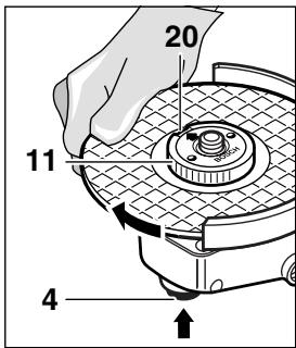
Lock the grinder spindle with the spindle lock button 4. Tighten the quick-clamping nut by forcefully turning the grinding disc in the clockwise direction.
A properly tightened undamaged, quick-clamping nut can be loosened by hand turning the knurled ring in the counterclockwise direction.
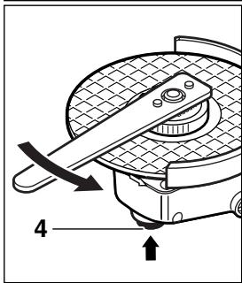
Never loosen a tight quick-clamping nut with pliers but use a two-pin spanner. Insert the two-hole spanner as shown in the illustration.
All grinding tools mentioned in this operating manual instruction can be used.
The permissible speed [rpm] or the circumferential speed [m/s] of the grinding tools used must at least match the values given in the table.
Therefore, always observe the permissible rotational/circumferential speed on the label of the grinding tool.
| max. [mm] | [mm] |  |  |
| D | b | d | [rpm] | [m/s] |
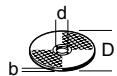 | 100 | 6 | 22.2 | 11 000 | 80 |
| 115 | 6 | 22.2 | 11 000 | 80 |
| 125 | 6 | 22.2 | 11 000 | 80 |
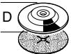 | 100 | - | - | 11 000 | 80 |
| 115 | - | - | 11 000 | 80 |
| 125 | - | - | 11 000 | 80 |
 | 70 | 30 | M 10 | 11 000 | 45 |
| 75 | 30 | M 14 | 11 000 | 45 |
Initial Operation
Observe correct mains voltage: The voltage of the power source must agree with the voltage specified on the nameplate of the machine. Equipment marked with 230 V can also be connected to 220 V.
Switching On and Off
To start the machine, press the On/Off switch 1 forward.
To lock-on, press the On/Off switch 1 down at the front until it engages.
To switch off the machine, release the On/Off switch 1 or press the rear tip of it down.

Test run!
Check the grinding tool before use. The grinding tool must be properly mounted and rotate freely. Perform a test run of at least 30 seconds without load. Do not use damaged, out-of-round or vibrating grinding tools.
Constant Electronic Control (PWS 8-125 CE/PWS 850 CE/PWS 9-125 CE)
Constant electronic control holds the speed constant at no-load and under load, and ensures uniform working performance.
Overload Protection (PWS 8-125 CE/PWS 850 CE/PWS 9-125 CE)
When overloaded, the motor comes to a stop. Relieve the load on the machine immediately and allow to cool for approx. 30 seconds at the highest no-load speed.
Speed Preselection (PWS 8-125 CE/PWS 850 CE/ PWS 9-125 CE)
Preselect the required speed using the thumb wheel 2 according to the table following the section "Product Specification" (reference values).
Operating Instructions
■ Clamp the workpiece if it does not remain stationary due to its own weight.
■ Do not strain the machine so heavily that it comes to a standstill.
■ Grinding and cutting discs become very hot while working; do not touch until they have cooled.
Rough Grinding
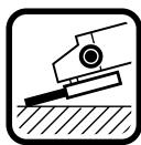
The best roughing results are achieved when setting the machine at an angle of 30^ to 40^ . Move the machine back and forth with moderate pressure. In this manner, the workpiece will not become too hot, does not discolour and no grooves are formed.

Never use a cutting disc for roughing.
Flap Disc
With the flap disc (accessory), curved surfaces and profiles (contour sanding) can be worked.
Flap discs have a considerably higher service life than sanding sheets, lower noise level and lower sanding temperatures.
Cutting
When cutting, do not press, jam or oscillate the machine. Work with moderate feed, adapted to the material being machined.
Do not reduce the speed of running down cutting discs by applying sideward pressure.
natural_image
Illustration of a robotic arm performing a circular motion maneuver on a rotating platform (no text or symbols)
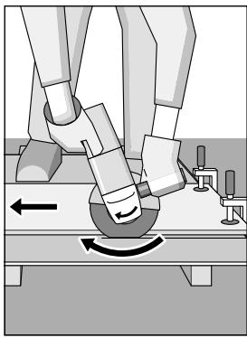
The direction in which the cutting is performed is important.
The machine must always work in an up-grinding motion. Therefore, never move the machine in the other direction! Otherwise, the danger exists of it being pushed uncontrolled out of the cut.
When cutting profiles and square pipes, it is best to start with the smallest cross section.
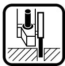
Cutting Stone
■ The machine must be used only for dry cutting/grinding.
It is best to use a diamond cutting disc. As a safety measure against jamming, use the cutting guide 17 with the special dust extraction protection guard.
Operate the machine with dust extraction only. In addition, wear a dust mask.
natural_image
Diagram of a mechanical device with rotating arm and pipe connection (no text or symbols)
The vacuum cleaner must be approved for the extraction of masonry dust.
Bosch provides suitable vacuum cleaners.
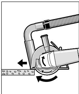
Switch on the machine and place the front part of the cutting guide on the workpiece.
Slide the machine with moderate feed, adapted to the material to be worked (Figure).
For cutting especially hard material, e. g., concrete with high pebble content, the diamond cutting disc can overheat and become damaged as a result. This is clearly indicated by circular sparking, rotating with the diamond cutting disc.
In this case, interrupt the cutting process and allow the diamond cutting disc to cool by running freely at no-load speed for a short time.
Noticeable decreasing work progress and circular sparking are indications of a diamond cutting disc that has become dull. Briefly cutting into abrasive material (e.g., lime-sand brick) can re-sharpen the disc.
Maintenance and Cleaning
■ Before any work on the machine itself, pull the mains plug.

For safe and proper working, always keep the machine and the ventilation slots clean.

In extreme working conditions, conductive dust can accumulate in the interior of the machine when working with metal. The protective insulation of the machine can be degraded. The use of a stationary extraction system is recommended in such cases as well as frequently blowing out the ventilation slots and installing a residual current device (RCD).
If the machine should fail despite the care taken in manufacturing and testing procedures, repair should be carried out by an after-sales service centre for Bosch power tools.
In all correspondence and spare parts orders, please always include the 10-digit order number given on the nameplate of the machine.
WARNING! Important instructions for connecting a new 3-pin plug to the 2-wire cable.
The wires in the cable are coloured according to the following code:

Do not connect the blue or brown wire to the earth terminal of the plug.
Important: If for any reason the moulded plug is removed from the cable of this machine, it must be disposed of safely.
Environmental Protection

Recycle raw materials instead of disposing as waste
The machine, accessories and packaging should be sorted for environmental-friendly recycling.
These instructions are printed on recycled paper manufactured without chlorine.
The plastic components are labelled for categorized recycling.
Service and Customer Assistance
www.bosch-pt.com
Great Britain
Robert Bosch Ltd. (B.S.C.)
P.O. Box 98
Broadwater Park
North Orbital Road
Denham-Uxbridge
Middlesex UB 9 5HJ
Service....+44 (0) 18 95 / 83 87 82
Advice line +44 (0) 18 95 / 83 87 91
Fax....+44 (0) 18 95 / 83 87 89
Ireland
Beaver Distribution Ltd.
Greenhills Road
Tallaght-Dublin 24
Service....+353 (0)1 / 414 9400
Fax....+353 (0)1 / 459 8030
Australia
Robert Bosch Australia Ltd.
RBAU/SPT2
1555 Centre Road
P.O. Box 66 Clayton
3168 Clayton/Victoria
📞 +61 (0)1 / 800 804 777
Fax....+61(0)1/800819520
www.bosch.com.au
E-Mail: CustomerSupportSPT@au.bosch.com
New Zealand
Robert Bosch Limited
14-16 Constellation Drive
Mairangi Bay
Auckland
New Zealand
We declare under our sole responsibility that this product is in conformity with the following standards or standardization documents: EN 50 144 according to the provisions of the directives 89/336/EEC, 98/37/EC.
Dr. Egbert Schneider
Senior Vice President
Engineering
Dr. Eckerhard Strötgen
Head of Product
Certification

i.v. Mogen
Subject to change without notice
natural_image
Illustration of a robotic arm performing a circular motion on a surface, with no visible text or symbols.
natural_image
Diagram of a mechanical device with rotating arms and fluid flow, no text or symbols present
Robert Bosch France S.A.
Service Après-vente/Outillage
Senior Vice President
Engineering
Dr. Eckerhard Strötgen
Head of Product
Certification

i.v. Nuoyen
natural_image
Illustration of a robotic arm performing a circular motion on a surface, with no visible text or symbols.
natural_image
Diagram of a mechanical tool interacting with a surface, showing motion arrows (no text or symbols)
Senior Vice President
Engineering
Dr. Eckerhard Strötgen
Head of Product
Certification

i.v. Nguyen
Montar as ferramentas abrasivas
natural_image
Illustration of a robotic arm performing a circular motion maneuver on a rotating platform (no text or symbols)
natural_image
Diagram of a mechanical device with rotating arm and pipe connection (no text or symbols)
Senior Vice President
Engineering
Dr. Eckerhard Strötgen
Head of Product
Certification


natural_image
Illustration of a robotic arm performing a circular motion on a surface, with no visible text or symbols.
natural_image
Diagram of a mechanical device with rotating components and directional arrows indicating motion (no text or symbols)
Senior Vice President
Engineering
Dr. Eckerhard Strötgen
Head of Product
Certification

i.v. Mogen
Snelspanmoer SDS-clic
natural_image
Illustration of a robotic arm performing a circular motion on a rotating platform (no text or symbols)
natural_image
Diagram of a mechanical device with tubing and rotating components (no text or symbols)
Senior Vice President
Engineering
Dr. Eckerhard Strötgen
Head of Product
Certification

i.v. Mogen
natural_image
Illustration of a robotic arm performing a circular motion on a surface, with no visible text or symbols.
natural_image
Diagram of a mechanical device with rotating components and directional arrows indicating motion (no text or symbols)
Senior Vice President
Engineering
Dr. Eckerhard Strötgen
Head of Product
Certification

i.v. Mogen
natural_image
Illustration of robotic arm performing a circular motion maneuver (no text or symbols)
natural_image
Diagram of a mechanical device with rotating arm and pipe connection (no text or symbols)
Senior Vice President
Engineering
Dr. Eckerhard Strötgen
Head of Product
Certification

i.v. Nguyen
(for M 14-slipespindel)
Avhengig av typen bruk må eventuelt vernedekselet 6 tas av og håndbeskyttelsen 12 monteres. Sett en spesiell festeflens 8 (tilbehør, bestillingsnummer 2 605 703 028) og lamellslipeskiven på slippspindel 5. Skru på spennmutter 10 og trekk til med hakenøkkelen.
Gummislipetallerken 13
(for M 14-slipespindel)
(for M 14-slipespindel)
natural_image
Illustration of robotic arm positioning on a platform with motion arrows (no text or symbols)
natural_image
Mechanical diagram showing a pipe joint with rotating components and directional arrows (no text or symbols)
Senior Vice President
Engineering
Dr. Eckerhard Strötgen
Head of Product
Certification

i.v. Nuoyen
natural_image
Illustration of a robotic arm performing a circular motion maneuver on a surface (no text or symbols)
natural_image
Diagram of a mechanical device with rotating components and flow arrows, no text or symbols present
Senior Vice President
Engineering
Dr. Eckerhard Strötgen
Head of Product
Certification

i.v. Nguyen
natural_image
Illustration of a robotic arm performing a circular motion on a surface, with no visible text or symbols.
natural_image
Diagram of a mechanical device with rotating arm and pipe, showing fluid flow direction (no text or symbols)
Senior Vice President
Engineering
Dr. Eckerhard Strötgen
Head of Product
Certification

i.v. Puoyen
natural_image
Illustration of a robotic arm performing a circular motion on a workbench, with no visible text or symbols.
natural_image
Diagram of a pipe valve assembly with directional arrows indicating flow or movement (no text or symbols)
Bosch San. ve Tic. A.S.
Ahi Evran Cad. No:1 Kat:22
Polaris Plaza
80670 Maslak/Istanbul
📞 +90 (0)212 / 335 06 00
Faks ...... +90 (0)212 / 346 00 48-49
CE Uygunluk beyani
Senior Vice President
Engineering
Dr. Eckerhard Strötgen
Head of Product
Certification

i.v. Moyen