USER MANUAL PST 650 PE BOSCH
natural_image
Diagram of a mechanical device with directional arrows indicating motion or force (no text or symbols)
text_image
B
15
text_image
C
PST 650 PE
PST 750 PE
16
17
18
text_image
D
5
PST 850 PE
text_image
E
PST 650 PE
PST 750 PE
19
20
21
17
natural_image
Technical illustration of a sewing machine needle cutting through a wooden surface, with no visible text or symbols
natural_image
Mechanical assembly diagram showing a sewing machine with clamping mechanism and labeled part (22), no readable text or symbols beyond labels
text_image
H
①
②
Gerätekennwerte
natural_image
Two identical oval-shaped objects with striped patterns, no text or symbols visible
Senior Vice President
Engineering
Dr. Eckerhard Strötgen
Head of Product
Certification

text_image
ppa. d### i.v. m#ge
Product Specifications
| Jigsaw | | PST 650 PE | PST 750 PE | PST 850 PE |
| Order number | | 0 603 381 7.. | 0 603 382 7.. | 0 603 383 7.. |
| Rated input power | [W] | 470 | 600 | 620 |
| Output power | [W] | 280 | 360 | 370 |
| Stroke rate at no load | [per min] | 500–3100 | 500–3100 | 500–3100 |
| Stroke | [mm] | 23 | 23 | 23 |
| Stroke rate selection | | ● | ● | ● |
| Pendelum action | | ● | ● | ● |
| Maximum cutting depth | | | | |
| in wood | [mm] | 68 | 75 | 85 |
| in aluminium | [mm] | 15 | 18 | 18 |
| in non-alloyed steel | [mm] | 4 | 6 | 8 |
| Bevel cuts (left/right) | [°] | 0–45 | 0–45 | 0–45 |
| Weight without mains cable approx. | [kg] | 1.9 | 2.4 | 2.4 |
| Protection class | | / II | / II | / II |
Please observe the order number of your machine. The trade names of the individual machines may vary.
Measured values determined according to EN 50 144.
The A-weighted sound pressure levels of the machines are typically:
PST 650 PE 82 dB(A)
PST 750 PE/PST 850 PE 84 dB(A)
The noise level when working can exceed 85 dB(A).
Wear ear protection!
PST 650 PE: The typically weighted acceleration is 5 m/s^2 .
PST 750 PE/PST 850 PE: The typical hand-arm vibration is below 2.5 m/s ^4 .
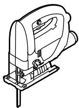
Intended Use
The machine is intended for making separating cuts and cutouts in wood, plastic, metal, ceramic plates and rubber while resting firmly on the workpiece. It is suitable for straight and curved cuts with bevel angles to 45^ . The saw blade recommendations are to be observed.
Product Elements
1 Stroke rate selection thumbwheel
2 On/off switch
3 Locking button for on/off switch
4 Blow-out opening/Vacuum hose*
5 Clamping lever for base plate (PST 850 PE)
6 Base plate
7 Lever for pendulum stroke adjustment
8 Switch for sawdust blowing device (PST 750 PE/PST 850 PE)
9 SDS lever for saw blade release
10 Guide roller
11 Saw blade*
12 Contact protector
13 Dust cover for vacuuming
14 Stroke rod
15 Splintering protector*
16 Cutting angle scale
17 Screw
18 Protractor**
19 Threaded hole
20 Front cut-out
21 Retainer
22 Parallel Guide/Circle Cutter*
* Optional accessories
** Commercially available (not included in the delivered items)
Not all the accessories illustrated or described are included in standard delivery.


For Your Safety
Working safely with this machine is possible only when the operating and safety information are read completely and the instructions contained therein are strictly followed.
In addition, the general safety notes in the enclosed booklet must be observed.
Before using for the first time, ask for a practical demonstration.
If the cable is damaged or cut through while working, do not touch the cable but immediately pull the mains plug. Never use the machine with a damaged cable.
■ Connect machines that are used in the open via a residual current device (RCD) with an actuating current of 30 mA maximum. Do not operate the machine in rain or moisture.
■ Wear safety glasses.
■ Working with material containing asbestos is not permitted.
■ Always direct the cable to the rear away from the machine.
- Secure the workpiece. A workpiece clamped with clamping devices or in a vice is held more secure than by hand.
■ Apply the machine to the workpiece only when switched on.
■ When working, never place a hand or fingers in front of the saw blade.
■ The cutting path must be free of obstacles both above and below.
■ When sawing, the complete surface of the base plate 6 must be in secure contact.
■ For the working of smaller or thin workpieces, use a stable foundation or a saw table (accessory).
■ Use only sharp, flawless saw blades. Replace immediately cracked, bent or dull saw blades.
■ When the cut is completed, switch off the machine and then pull the saw blade out of the cut only after it has come to a standstill (danger of kick-back).
■ Always switch the machine off and wait until it has come to a standstill before placing it down.
■ After switching off, do not brake the saw blade to a stop by applying side pressure.
■ Never allow children to use the machine.
- Bosch is able to ensure flawless functioning of the machine only if the original accessories intended for it are used.
A Inserting/Changing the Saw Blade
■ Before any work on the machine itself, pull the mains plug.
■ For inserting or changing the saw blade 11, the wearing of protective gloves is recommended.
① Inserting the Saw Blade
Insert the saw blade (teeth in the cutting direction) into the stroke rod 14 until it latches. The SDS clamping lever 9 springs to the rear and locks the saw blade.
Take care when inserting the saw blade that the rear edge of the saw blade rests in the groove of the guide roller 10.
② Ejecting the Saw Blade
To eject the saw blade, turn the SDS lever 9 to the front in the insertion position. The saw blade is released and ejected.
Dust/Chip Vacuuming
■ Dust produced while working can be detrimental to health, inflammable or explosive. Suitable protection measures are required.
Examples: Some dusts are considered to be carcinogenic. Use suitable dust/chip extraction and wear a dust protection mask.
■ Light metal dust can burn or explode. Always keep the work place clean since material mixtures are especially dangerous.
Cover Guard
When using a vacuum cleaner, always mount the dust cover 13 and slide it completely downward.
Attaching: Insert the cover guard from above into the guide and slide downward until it latches.
Removing: Take hold of the cover guard on the sides and pull off in the upward direction.
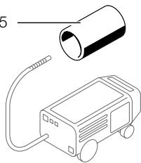
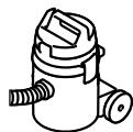
Connection for a Vacuum Cleaner
(Accessory pages)
Connect the vacuuming hose (19 mm dia., accessory) directly to the blow-out opening 4.
The vacuum cleaner must be suitable for the material to be worked.
When vacuuming dry dust that is especially detrimental to health or carcinogenic, use a special vacuum cleaner.
Putting into Operation
Ensure that the mains voltage is correct!
The voltage of the power source must agree with the value given on the nameplate of the machine. Machines designated for 230 V can also be operated with 220 V.
Switching On/Off
To switch on the machine, press the on/off switch 2.
Lock the depressed on/off switch 2 by pressing the lock-on button 3.
To switch off the machine, release the on/off switch 2 or push and then release it.
Continuously Variable Stroke Rate Adjustment
Light application of pressure on the on/off switch 2 results in a low stroke rate. Increasing pressure results in a higher stroke rate.
Stroke Rate Preselection
The required stroke rate can be preselected (also during operation) using the thumbwheel 1.
The required stroke rate is dependent on the material and the working conditions and can be determined by a practical trial.
Sawdust Blower (PST 750 PE/PST 850 PE)
With the air stream of the sawdust blowing device 8, the cutting line can be kept free of dust.

Blower effect switched on:
For working with wood, plastic and other materials that produce large amounts of dust.

Blower effect switched off:
For working with metals and when cooling or lubricating agents are used.
Pendelum Action Setting
The pendulum action that is adjustable in four steps makes possible the optimum adaptation of cutting speed and performance as well as cutting pattern to the material being worked.
The pendulum action can be set with the adjustment lever 7 (also when the machine is running).
Step 0: No pendulum action
Step I: Small pendulum action
Step II: Medium pendulum action
Step III: Large pendulum action
It is recommended that:
- The finer and cleaner the cut edge should be, the smaller the pendulum action step selected should be or the pendulum action switched off.
- The pendulum action be switched off for working with thin materials such as sheet metal, for example.
- The small pendulum action step be used in hard materials such as steel, for example.
- In soft materials and for cuts in the direction of the grain, the maximum pendulum action be used.
The optimal setting can be determined in practice.
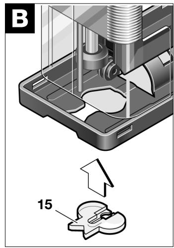
C/D Adjusting the Cutting Angle
PST 650 PE/PST 750 PE
Loosen the screw 17 and slide the base plate 6 forward somewhat in the direction of the saw blade. The base plate can be swung to both sides by 45°.
Any cutting angle can be set exactly with a protractor 18.
For the setting of precise bevel angles, the base plate has a scale 16 with detent points in 15^ steps. Slide the rotated base plate in the direction of the blow-out opening until it latches.
After adjusting, retighten the screw 17.
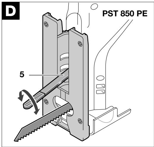
PST 850 PE
Swing the clamping lever 5 out of the base plate 6 and loosen the base plate by turning the clamping lever anti-clockwise.
Then slide the base plate 6 somewhat in the direction of the saw blade. The base plate can be swung to both sides by 45^ .
Any cutting angle can be set exactly with a protractor 18.
For the setting of precise bevel angles, the base plate has a scale 16 with detent points in 15^ steps. Slide the rotated base plate in the direction of the blow-out opening until it latches.
Retighten the clamping lever 5 by turning clockwise and swing back into the base plate. Take care that the clamping lever is completely sunk into the base plate 6.
For sawing close to edges, the foot plate can be offset to the rear.
- With the base plate repositioned, the cutting angle cannot be changed.
- The circle cutter/parallel guide 22 as well as the splintering protector 15 cannot be used.
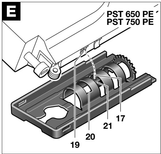
PST 650 PE/PST 750 PE
Unscrew the screw 17 completely. Lift off the base plate and reposition so that the screw 17 with the retainer 21 fits in the front cut-out 20 of the base plate and can be screwed into the threaded hole 19.
Before tightening the screw 17, press the base plate to the rear until it latches.
PST 850 PE
Swing the clamping lever 5 out of the base plate 6 and loosen the base plate by turning the clamping lever anti-clockwise.
Slide the base plate 6 to the stop in the direction of the blow-out opening.
Retighten the clamping lever 5 by turning clockwise and swing back into the base plate. Take care that the clamping lever is completely sunk into the base plate 6.
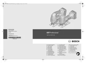
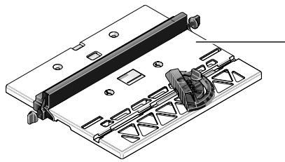
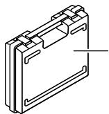
B Splintering Protector
To prevent the splintering of the surface when sawing wood, insert the splintering protector into the base plate 6 from below.
The splintering protector can be used only with certain types of saw blades.
Tips
After working for a long period with a low stroke rate, allow the machine to cool by running for approx. 3 minutes without a saw blade and at maximum stroke rate.
For narrow curves, use a thin saw blade.
When sawing metal or similar material, apply a cooling or lubricating agent along the cutting line.
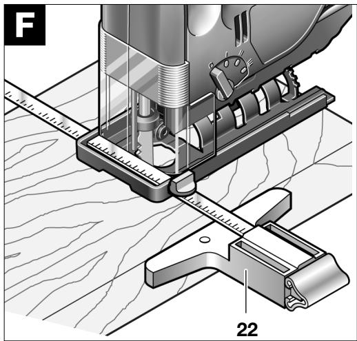
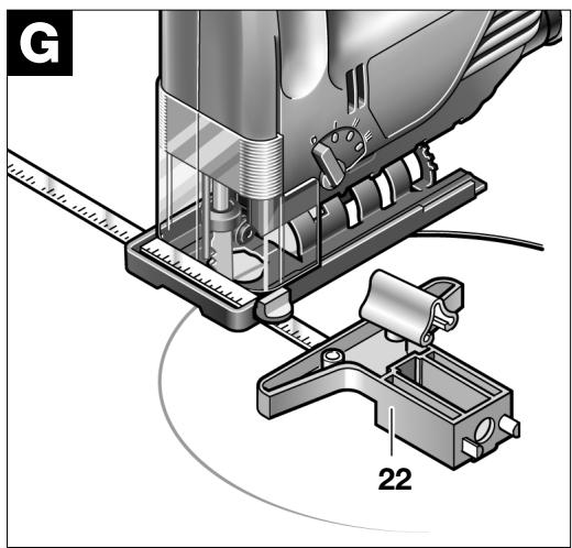
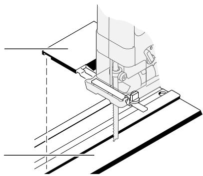
F /G Parallel Guide/Circle Cutter (Accessory)
Maximum material thickness: 30 mm
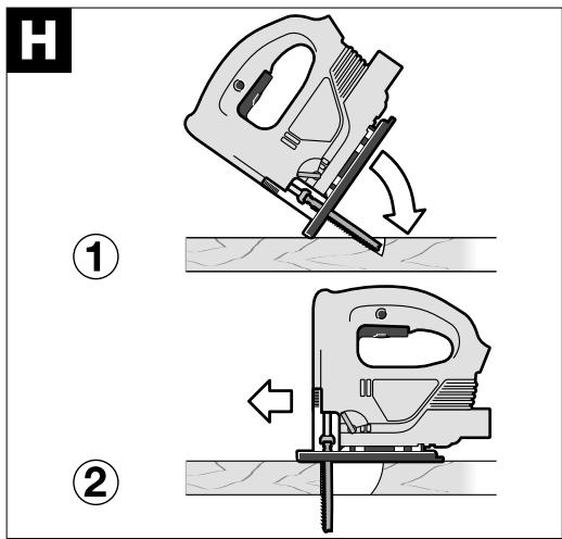
H Plunge Sawing
Plunge cutting may be used only on soft materials such as wood, aerated concrete, gypsum plaster boards, etc.!
Use only short saw blades.
Place the front edge of the base plate on the workpiece and switch on. Press the machine firmly against the workpiece and plunge the saw blade slowly into the workpiece.
As soon as the complete surface of the base plate rests on the work piece, continue to saw along the cutting line.
Maintenance and Cleaning
■ Before any work on the machine itself, pull the mains plug.
■ For safe and efficient working, always keep the machine and the ventilation slots clean.
To avoid malfunctions, do not work with materials that produce large amounts of dust from below or overhead. Clean the saw blade holder regularly, for example, by lightly tapping the machine on a flat surface.
In extreme working conditions, conductive dust can accumulate in the interior of the machine when working with metal. The protective insulation of the machine can be degraded. The use of a stationary extraction system is recommended in such cases as well as the frequent blowing out of the ventilation slots and the installation of a residual current circuit breaker (RCD).
Lubricate the guide roller 10 from time to time with a drop of oil and check for wear. If it is worn, it must be replaced.
WARNING
Important instructions for connecting a new 3-pin plug to the 2-wire cable.
The wires in the cable are coloured according to the following code:

text_image
Strain relief
Live = brown
Neutral = blue
To be fitted
by qualified
professionals only
Do not connect the blue or brown wire to the earth terminal of the plug.
Important: If the plug on the cable of this machine must be replaced, dispose of the old plug to prevent misuse.
If the machine should fail despite the care taken in manufacture and testing, repair should be carried out by an authorised customer services agent for Bosch power tools.
For all correspondence and spare parts orders, always include the 10-digit order number of the machine.
Environmental Protection

Recycle raw materials instead of disposing as waste.
The machine, accessories and packaging should be submitted for environment-friendly recycling.
These instructions are printed on recycled paper manufactured without chlorine.
The plastic components are labelled for categorised recycling.
We declare under our sole responsibility that this product is in conformity with the following standards or standardization documents:
EN 50 144 according to the provisions of the directives 89/336/EEC, 98/37/EC.
Dr. Egbert Schneider
Senior Vice President
Engineering
Dr. Eckerhard Strötgen
Head of Product
Certification

text_image
ppa. dawala
i.v. Mige
Specification subject to alteration without notice
Senior Vice President
Engineering
Dr. Eckerhard Strötgen
Head of Product
Certification

natural_image
Two identical oval-shaped objects with striped patterns, no text or symbols visible
Senior Vice President
Engineering
Dr. Eckerhard Strötgen
Head of Product
Certification

text_image
ppa. dawala

Dr. Egbert Schneider
Senior Vice President
Engineering
Dr. Eckerhard Strötgen
Head of Product
Certification

text_image
ppa. deuena
i.v. Mige
Dr. Egbert Schneider
Senior Vice President
Engineering
Dr. Eckerhard Strötgen
Head of Product
Certification

text_image
ppa. dawala

Senior Vice President
Engineering
Dr. Eckerhard Strötgen
Head of Product
Certification

text_image
ppa. Mauca

natural_image
Two identical oval-shaped objects with striped patterns, no text or symbols visible
Dr. Egbert Schneider
Senior Vice President
Engineering
Dr. Eckerhard Strötgen
Head of Product
Certification

text_image
ppa. Mauka i.v. Mige
Dr. Egbert Schneider
Senior Vice President
Engineering
Dr. Eckerhard Strötgen
Head of Product
Certification

text_image
ppa. Mauka i.v. Mige
Dr. Egbert Schneider
Senior Vice President
Engineering
Dr. Eckerhard Strötgen
Head of Product
Certification

text_image
ppa. Mauca

Senior Vice President
Engineering
Dr. Eckerhard Strötgen
Head of Product
Certification

text_image
ppa. dawick
i.v. Mige
Dr. Egbert Schneider
Senior Vice President
Engineering
Dr. Eckerhard Strötgen
Head of Product
Certification

text_image
ppa. dawaka

PST 750 PE/PST 850 PE:
Tipik el/kol titreşimi 2,5 m/s² ‘den düşük.
Dr. Egbert Schneider
Senior Vice President
Engineering
Dr. Eckerhard Strötgen
Head of Product
Certification

© Kundenberater:....01 80/3 33 57 99
Österreich
ABE Service GmbH
Service and Customer Advice
Great Britain
Robert Bosch Ltd. (B.S.C.)
P.O. Box 98
Broadwater Park
North Orbital Road
Denham-Uxbridge
Middlesex UB 9 5HJ
© Service .....+44 (0) 18 95/83 87 82
© Advice line. . . . . . . . . . . . . +44 (0) 18 95/83 87 91
Fax .....+44 (0) 18 95/83 87 89
Ireland
Beaver Distribution Ltd.
Greenhills Road
Tallaght-Dublin 24
© Service .....+ 353 (0)1/414 9400
Fax....+353(0)1/4598030
Australia
Robert Bosch Australia L.t.d.
RBAU/SBT2
1555 Centre Road
P.O. Box 66 Clayton
3168 Clayton/Victoria
📞 +61 (0)1/800 804 777
Fax ..... +61 (0)1/800 819 520
www.bosch.com.au
E-Mail: CustomerSupportSPT@au.bosch.com
New Zealand
Robert Bosch Limited
14-16 Constellation Drive
Mairangi Bay
Auckland
New Zealand
📞 +64 (0)9/47 86 158
Fax ..... +64 (0)9/47 82 914
Service Après-Vente
France
Robert Bosch France S.A.
Service Après-vente Outillage
natural_image
Technical line drawing of a mechanical clamp or bracket assembly (no text or symbols)
2 607 001 201
2 607 001 069
2 602 317 031
(1,4 m)
natural_image
Technical line drawing of a mechanical assembly with no visible text or symbols
natural_image
Technical line drawing of a mechanical assembly with no visible text or symbols
MT 300 WP
0 603 037 103
2 600 306 005
natural_image
Line drawing of a cylindrical device connected to a rectangular electronic device (no text or symbols)
natural_image
Isometric line drawing of a mechanical component with no text or symbols
PST 650 PE: 2 605 438 429
PST 750 PE/
PST 850 PE: 2 605 438 430
2 607 010 079
(5x)


1 609 390 474

PAS 10-20
PAS 850
natural_image
Line drawing of a manual pusher with base mount (no text or symbols)

2 600 793 009 (3 m)
1 610 793 002 (5 m)

1 609 200 933

PAS 11-25 F
PAS 11-25
PAS 12-50 F

2 607 000 748
PAS 12-27 F
PAS 12-27
PAS 11-21
bar
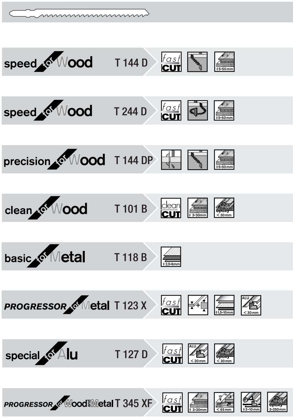
| Category | Item | Value |
|---|---|---|
| speed for Wood | T 144 D | fast CUT ±5-50mm |
| speed for Wood | T 244 D | fast CUT ±5-50mm |
| precision for Wood | T 144 DP | fast CUT ±5-50mm |
| clean for Wood | T 101 B | clean CUT ±3-30mm epoxy < 30 mm |
| basic for Metal | T 118 B | ±2.5-6mm |
| PROGRESSOR for Metal | T 123 X | fast CUT ±1.5-10mm ALU < 30 mm |
| special for Alu | T 127 D | fast CUT ALU < 30 mm epoxy < 30 mm |
| PROGRESSOR for Wood | T 345 XF | fast CUT ±3-30mm < 65 mm ±3-10mm epoxy 3-250 mm |

text_image
Chlor
BOSCH

Robert Bosch GmbH
Printed in Switzerland – Imprimé en Suisse