
PSR 960 - Drill BOSCH - Free user manual and instructions
Find the device manual for free PSR 960 BOSCH in PDF.
User questions about PSR 960 BOSCH
0 question about this device. Answer the ones you know or ask your own.
Ask a new question about this device
Download the instructions for your Drill in PDF format for free! Find your manual PSR 960 - BOSCH and take your electronic device back in hand. On this page are published all the documents necessary for the use of your device. PSR 960 by BOSCH.
USER MANUAL PSR 960 BOSCH
Operating Instructions
natural_image
3D rendering of a Bosch electric drill with visible brand logo and control buttons (no text or symbols on the device itself)
Deutsch
English
Français
Español
Português
Italiano
Nederlands
Dansk
Svenska
Norsk
Suomi
Ελληνικά
Türkçe


text_image
1 2 3 4 5 6 7 BOSCH PSR 960 PSR 1200 PSR 1440
text_image
A 7
text_image
B 7 82 • 2 609 140 186 • 02.02
Gerätekennwerte
natural_image
Diagram showing two identical rocket-like shapes with curved arrows indicating motion or rotation, labeled (a) and (b), no text or symbols present.text_image
Ni-Cd max.50°CNickel-Cadmium-Akku:
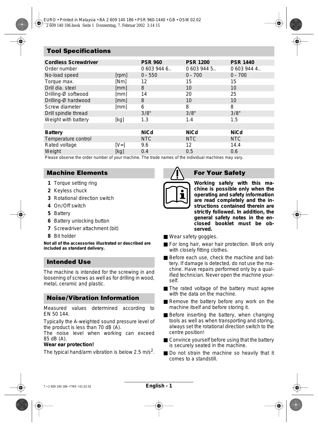
| Cordless Screwdriver | PSR 960 | PSR 1200 | PSR 1440 | |
| Order number | 0 603 944 6.. | 0 603 944 5.. | 0 603 944 4.. | |
| No-load speed | [rpm] | 0–550 | 0–700 | 0–700 |
| Torque max. | [Nm] | 12 | 15 | 15 |
| Drill dia. steel | [mm] | 8 | 10 | 10 |
| Drilling-∅ softwood | [mm] | 14 | 20 | 25 |
| Drilling-∅ hardwood | [mm] | 8 | 10 | 10 |
| Screw diameter | [mm] | 6 | 8 | 8 |
| Drill spindle thread | 3/8" | 3/8" | 3/8" | |
| Weight with battery | [kg] | 1.3 | 1.4 | 1.5 |
| Battery | NiCd | NiCd | NiCd | |
| Temperature control | NTC | NTC | NTC | |
| Rated voltage | [V=] | 9.6 | 12 | 14.4 |
| Weight | [kg] | 0.4 | 0.5 | 0.6 |
Please observe the order number of your machine. The trade names of the individual machines may vary.
Machine Elements
1 Torque setting ring
2 Keyless chuck
3 Rotational direction switch
4 On/Off switch
5 Battery
6 Battery unlocking button
7 Screwdriver attachment (bit)
8 Bit holder
Not all of the accessories illustrated or described are included as standard delivery.
Intended Use
The machine is intended for the screwing in and loosening of screws as well as for drilling in wood, metal, ceramic and plastic.
Noise/Vibration Information
Measured values determined according to EN 50 144.
Typically the A-weighted sound pressure level of the product is less than 70 dB (A).
The noise level when working can exceed 85 dB (A).
Wear ear protection!
The typical hand/arm vibration is below 2.5 m/s^2 .

For Your Safety

Working safely with this machine is possible only when the operating and safety information are read completely and the instructions contained therein are strictly followed. In addition, the general safety notes in the enclosed booklet must be observed.
■ Wear safety goggles.
■ For long hair, wear hair protection. Work only with closely fitting clothes.
■ Before each use, check the machine and battery. If damage is detected, do not use the machine. Have repairs performed only by a qualified technician. Never open the machine yourself.
■ The rated voltage of the battery must agree with the data on the machine.
■ Remove the battery before any work on the machine itself and before storing it.
■ Before inserting the battery, when changing tools as well as when transporting and storing, always set the rotational direction switch to the centre position!
■ Convince yourself before using that the battery is securely seated in the machine.
■ Do not strain the machine so heavily that it comes to a standstill.
■ Hold the machine tightly: When driving in screws, high reaction moments can briefly occur.
■ Never allow children to use the machine.
■ Bosch is only able to ensure perfect operation of the machine if the original accessories intended for it are used.
Battery and Battery Charger
■ The enclosed operating instructions for the battery charger must be read carefully!
■ The battery and battery charger are designed to match each other. When charging the battery, use only a Bosch battery charger designed for it with a charging voltage that corresponds with the battery (see type plate). Combining different rated voltages causes damage to the battery charger.
- Allow a heated battery to cool before charging.
■ Protect the battery from heat and fire: Danger of explosion! Do not place the battery on radiators or expose to strong sun rays for a longer time; temperatures over 50 °C cause damage.
■ Do not open the battery, and protect it from impact. Store in a dry and frost-free place.
■ Cover the contacts of a removed battery. Danger of fire results when shorted by a metal object!
■ Do not throw the battery into the household waste, into fire or water.
Before Putting into Operation
Battery Charging
A battery that is new or has not been used for a longer period does not develop its full capacity until after approximately 5 charging/discharging cycles.
To remove the battery 5, press the unlocking buttons 6 and pull out the battery downwards. Do not exert any force.
The battery is equipped with an NTC temperature control which allows charging only within a temperature range of between 0 °C and 45 °C. A long battery service life is achieved in this manner.
A significantly reduced working period after charging indicates that the batteries are used and must be replaced.
■ Observe the notes on environmental protection.
Changing the Tool
Open the drill chuck until the tool can be inserted. Insert the tool.
Hold the rear collar tight and firmly tighten the front collar by hand, until the “clicking” of the locking action is no longer heard. This automatically locks the chuck.
The locking is released again when the front collar is turned in the opposite direction to remove the tool.
Screwdriving (see figures A + B)
Directly clamp the screwdriver bit into the drill chuck or use the additional universal bit holder 8 when operating with hex shank bits 7.
Initial Operation
Inserting the Battery
Set the rotational direction switch 3 to the centre position = lock-off and allow the charged battery 5 to engage into the handle.
Switching On and Off
To start the machine press the On/Off switch 4.

The machine runs with variable speed between 0 and maximum, depending on the pressure applied to the On/Off switch 4. Light pressure results in a low rotational speed thus allowing smooth, controlled starts. Do not strain the machine so heavily that it comes to a standstill.
To switch off the machine, release the On/Off switch 4.
Reversing the Rotational Directions

Operate the rotational direction switch 3 only at a standstill.
The rotational direction switch 3 is used to reverse the rotational direction of the machine. However, this is not possible with the On/Off switch 4 actuated.

text_image
Diagram illustrating two stages of a mechanical or fluid system with directional arrows and labeled components (a) and (b)For drilling and driving in screws, set the rotational direction CLOCKWISE ⓑ.
To drive out screws, switch to the rotational direction ANTICLOCKWISE ⓐ.
Setting the Torque
Carry out a practical test to determine with which of the 5 settings of the torque setting ring 1 the screws are driven flush into the material.
1
Low setting, e.g., small screws, soft materials.
5
High setting, e. g., large screws, hard materials.
With the correct setting, the clutch disengages as soon as the screw is driven flush into the material or the set torque is reached. Select a higher setting when driving out screws, or set to the “Drilling” symbol. The correct setting is to be determined by practical testing.
Drilling

Set the torque setting ring 1 to the "Drilling" symbol.
Operating Instructions
Run-On Brake
When releasing the On/Off switch 4 the speed of the drill chuck is reduced to a stop, thus preventing the run-on of the tool.
For screwdriving applications, wait until the screw is flush with the material and then release the On/Off switch 4. The screw head does not penetrate into the material then.
Replacing the Drill Chuck
For machines without a drill spindle locking facility, the chuck must be changed by an authorised after-sales service shop for Bosch power tools.

The chuck must be tightened with a torque of approx. 35–40 Nm.
Tips
It is advisable to first drill a pilot hole before attempting to screw in large, long screws in hard material.
Maintenance and Cleaning
■ Before any work on the machine itself, remove the battery.

For safe and proper working, always keep the machine and the ventilation slots clean.
If the machine should fail despite the care taken in manufacturing and testing procedures, repair should be carried out by an after-sales service centre for Bosch power tools.
In all correspondence and spare parts orders, please always include the 10-digit order number given on the nameplate of the machine.
Environmental Protection

Recycle raw materials instead of disposing as waste.
The machine, accessories and packaging should be sorted for environmental-friendly recycling.
These instructions are printed on recycled paper manufactured without chlorine.
The plastic components are labelled for categorized recycling.

text_image
Ni-Cd max 50°CNickel-cadmium-battery: If your product is equipped with a nickel-cadmium-battery, the battery must be collected, recycled or disposed of in an environmentally-friendly way.
Defective or worn out batteries must be recycled according to the guidelines 91/157/EEC.
Batteries no longer suitable for use can be directly returned at:
Great Britain
Robert Bosch Ltd. (B.S.C.)
P.O. Box 98
Broadwater Park
North Orbital Road
Denham-Uxbridge
GB-Middlesex UB 9 5HJ
Service....+44 (0) 18 95 / 83 87 82
C Advice line ....+44 (0) 18 95 / 83 87 91
Fax....+44 (0) 18 95 / 83 87 89
Service and Customer Assistance
www.bosch-pt.com
Great Britain
Robert Bosch Ltd. (B.S.C.)
P.O. Box 98
Broadwater Park
North Orbital Road
Denham-Uxbridge
GB-Middlesex UB 9 5HJ
Service.... +44 (0) 18 95 / 83 87 82
Advice line ....+44 (0) 18 95 / 83 87 91
Fax....+44 (0) 18 95 / 83 87 89
Ireland
Beaver Distribution Ltd.
Greenhills Road
IRL-Tallaght-Dublin 24
Service....+353 (0)1 / 414 9400
Fax....+353 (0)1 / 459 8030
Australia
Robert Bosch Australia L.t.d.
RBAU/SPT2
1555 Centre Road
P.O. Box 66 Clayton
AUS-3168 Clayton/Victoria
C +61 (0)1 / 800 804 777
Fax....+61 (0)1 / 800 819 520
www.bosch.com.au
E-Mail: CustomerSupportSPT@au.bosch.com
New Zealand
Robert Bosch Limited
14-16 Constellation Drive
Mairangi Bay
Auckland
New Zealand
(€ Declaration of Conformity
We declare under our sole responsibility that this product is in conformity with the following standards or standardization documents. EN 50 144 (Battery powered products) and EN 60 335 (Battery charger) according to the provisions of the directives 73/23/EEC, 89/336/EEC, 98/37/EC.
CE 02
Dr. Gerhard Felten Dr. Eckerhard Strötgen
ppa. Feisen i.v. Morgen
Subject to change without notice


text_image
Diagram illustrating two stages of a mechanical or fluid system with directional arrows and labeled points (a) and (b)text_image
Ni-Cd max.50°CRobert Bosch France S.A.
Service Après-vente/Outillage
After Sales Service Outillage
Rue Henri Genesse 1
BE-1070 Bruxelles

+32 (0)2 / 525.50.29

+32 (0)2 / 525.54.30

Service conseil client ..... +32 (0)2 / 525.53.07

Mail : Outillage.Gereedschappen@be.bosch.com
Suisse
Robert Bosch AG
natural_image
Illustration of two identical figures with curved arrows indicating motion or rotation, labeled (a) and (b), no text or symbols present.text_image
Ni-Cd max.50°Cnatural_image
Illustration of two identical figures with curved arrows indicating motion or rotation, labeled (a) and (b), no text or symbols present.text_image
Ni-Cd max.50°Ctext_image
Diagram illustrating two stages of a mechanical or fluid system with directional arrows and labeled components (a) and (b)natural_image
Illustration of two identical rocket heads with curved arrows indicating motion or movement (no text or symbols)text_image
Ni-Cd max.50°Ctext_image
Diagram illustrating two stages of a mechanical or fluid system with directional arrows and labeled components (a) and (b)Nikkel-cadmium-akku:
text_image
Diagram illustrating two stages of a bird-like shape with directional arrows and labeled parts (a) and (b)text_image
Ni-Cd max.50°Ctext_image
Diagram illustrating two stages of a human head with directional arrows and labeled positions (a) and (b)Turtalls-innstilling
text_image
Ni-Cd max.50°Ctext_image
Diagram illustrating two mechanical or fluid dynamics states labeled (a) and (b), with directional arrows indicating flow or movement.text_image
Ni-Cd max.50°Ctext_image
Diagram illustrating two stages of a bird-like shape with directional arrows and labeled parts (a) and (b)text_image
Ni-Cd max.50°Ctext_image
Diagram illustrating two stages of a mechanical or fluid system with directional arrows and labeled components (a) and (b)text_image
Ni-Cd max.50°CBosch San. ve Tic. A.S.
Ahi Evran Cad. No:1 Kat:22
Polaris Plaza
TR-80670 Maslak/Istanbul
C +90 (0)212 / 335 06 00
Faks ....+90 (0)212 / 346 00 48–49
CE Uygunluk beyanı
natural_image
Technical illustration of a mechanical connector or fitting (no text or symbols)2 607 000 205

natural_image
Illustration of a small electrical component connected to a larger black-and-white electrical box with coiled cable (no text or symbols)AL 300 SV
2 607 224 ...
[Non-Text]

2 607 000 221*
0,8 x 5,5 mm
⊕

2 607 000 239*
PH Nr. 2
⊕

2 607 000 248*
PZ Nr. 2
[Non-Text]

2 607 000 258*
T 20
C

2 607 000 317*
SW 3 mm


natural_image
Line drawing of a person wearing a helmet and holding a device (no text or symbols)2 605 439 014
2 605 439 013
2 605 439 012
2 605 439 015

natural_image
Isometric line drawing of a rectangular electronic component with internal structure (no text or symbols)2 609 160 062


text_image
ChlorBOSCH

Robert Bosch GmbH
natural_image
Simple crosshair symbol with concentric circles and intersecting lines (no text or labels)
