
PSB 600 RE - Drill BOSCH - Free user manual and instructions
Find the device manual for free PSB 600 RE BOSCH in PDF.

User questions about PSB 600 RE BOSCH
0 question about this device. Answer the ones you know or ask your own.
Ask a new question about this device
Download the instructions for your Drill in PDF format for free! Find your manual PSB 600 RE - BOSCH and take your electronic device back in hand. On this page are published all the documents necessary for the use of your device. PSB 600 RE by BOSCH.
USER MANUAL PSB 600 RE BOSCH
Power Tools Division
70745 Leinfelden-Echterdingen
www.bosch-pt.com
2609002371 (2008.01) O/125
PSB
530 RA | 600 RE | 650 RE | 650 RA

BOSCH
de Originalbetriebsanleitung
en Original instructions
fr Notice originale
es Manual original
pt Manual original
it Istruzioni originali
nl Oorspronkelijke
gebruksaanwijzing
da Original brugsanvisning
sv Bruksanvising i original
no Original driftsinstruks
fi Alkuperäiset ohjeet
el Pnpotuno oBnyiw xphonc
tr Original isletmet talimati

Deutsch. 6
English. Page 16
Francais.. Page 25
Espanol. 35
Portugues . 45
Italiano 55
Nederlands.. 65
Dansk . 74
Svenska. Sida 82
Norsk. 90
Suomi . 98
Eληνικά Σελδα 106
Türkce Sayfa 116

PSB 650 RA

Dr. Egbert Schneider Senior Vice President Engineering
Dr. Eckerhard Strötgen
Head of Product Certification
General Power Tool SafetyWarnings
WARNING
Read all safety warnings and all instructions. Failure to follow the
warnings and instructions may result in electric shock, fire and/or serious injury.
Save all warnings and instructions for future reference.
The term "power tool" in the warnings refers to your mains-operated (corded) power tool or battery-operated (cordless) power tool.
1) Work area safety
a) Keep work area clean and well lit. Cluttered or dark areas invite accidents.
b) Do not operate power tools in explosive atmospheres, such as in the presence of flammable liquids, gases or dust. Power tools create sparks which may ignite the dust or fumes.
c) Keep children and bystanders away while operating a power tool. Distractions can cause you to lose control.
2) Electrical safety
a) Power tool plugs must match the outlet. Never modify the plug in any way. Do not use any adapter plugs with earthed (grounded) power tools. Unmodified plugs and matching outlets will reduce risk of electric shock.
b) Avoid body contact with earthed or grounded surfaces, such as pipes, radiators, ranges and refrigerators. There is an increased risk of electric shock if your body is earthed or grounded.
c) Do not expose power tools to rain or wet conditions. Water entering a power tool will increase the risk of electric shock.
d) Do not abuse the cord. Never use the cord for carrying, pulling or unplugging the power tool. Keep cord away from heat, oil, sharp edges and moving parts. Damaged or entangled cords increase the risk of electric shock.
e) When operating a power tool outdoors, use an extension cord suitable for outdoor use. Use of a cord suitable for outdoor use reduces the risk of electric shock.
f) If operating a power tool in a damp location is unavoidable, use a residual current device (RCD) protected supply. Use of an RCD reduces the risk of electric shock.
3) Personal safety
a) Stay alert, watch what you are doing and use common sense when operating a power tool. Do not use a power tool while you are tired or under the influence of drugs, alcohol or medication. A moment of inattention while operating power tools may result in serious personal injury.
b) Use personal protective equipment. Always wear eye protection. Protective equipment such as dust mask, non-skid safety shoes, hard hat, or hearing protection used for appropriate conditions will reduce personal injuries.
c) Prevent unintentional starting. Ensure the switch is in the off-position before connecting to power source and/or battery pack, picking up or carrying the tool. Carrying power tools with your finger on the switch or energising power tools that have the switch on invites accidents.
d) Remove any adjusting key or wrench before turning the power tool on. A wrench or a key left attached to a rotating part of the power tool may result in personal injury.
e) Do not overreach. Keep proper footing and balance at all times. This enables better control of the power tool in unexpected situations.
f) Dress properly. Do not wear loose clothing or jewellery. Keep your hair, clothing and gloves away from moving parts. Loose clothes, jewellery or long hair can be caught in moving parts.
g) If devices are provided for the connection of dust extraction and collection facilities, ensure these are connected and properly used. Use of dust collection can reduce dust-related hazards.
4) Power tool use and care
a) Do not force the power tool. Use the correct power tool for your application. The correct power tool will do the job better and safer at the rate for which it was designed.
b) Do not use the power tool if the switch does not turn it on and off. Any power tool that cannot be controlled with the switch is dangerous and must be repaired.
c) Disconnect the plug from the power source and/or the battery pack from the power tool before making any adjustments, changing accessories, or storing power tools. Such preventive safety measures reduce the risk of starting the power tool accidentally.
d) Store idle power tools out of the reach of children and do not allow persons unfamiliar with the power tool or these instructions to operate the power tool.
Power tools are dangerous in the hands of untrained users.
e) Maintain power tools. Check for misalignment or binding of moving parts, breakage of parts and any other condition that may affect the power tool's operation. If damaged, have the power tool repaired before use. Many accidents are caused by poorly maintained power tools.
f) Keep cutting tools sharp and clean. Properly maintained cutting tools with sharp cutting edges are less likely to bind and are easier to control.
g) Use the power tool, accessories and tool bits etc. in accordance with these instructions, taking into account the working conditions and the work to be performed.
Use of the power tool for operations different from those intended could result in a hazardous situation.
5) Service
a) Have your power tool serviced by a qualified repair person using only identical replacement parts. This will ensure that the safety of the power tool is maintained.
Machine-specific SafetyWarnings
Wear hearing protection when using impact drills. The influence of noise can lead to loss of hearing.
Always use the auxiliary handle supplied with the machine. Loss of control can cause personal injury.
- Use appropriate detectors to determine if utility lines are hidden in the work area or call the local utility company for assistance. Contact with electric lines can lead to fire and electric shock. Damaging a gas line can lead to explosion. Penetrating a water line causes property damage or may cause an electric shock.
- Switch off the power tool immediately when the tool insert jams. Be prepared for high reaction torque that can cause kickback. The tool insert jams when:
- the power tool is subject to overload or
- it becomes wedged in the workpiece.
Hold the power tool only by the insulated gripping surfaces when performing an operation where the cutting tool may contact hidden wiring or its own cord. Contact with a "live" wire will also make exposed metal parts of the power tool "live" and shock the operator.
- When working with the machine, always hold it firmly with both hands and provide for a secure stance. The power tool is guided more secure with both hands.
- Secure the workpiece. A workpiece clamped with clamping devices or in a vice is held more secure than by hand.
- Keep your workplace clean. Blends of materials are particularly dangerous. Dust from light alloys can burn or explode.
Always wait until the machine has come to a complete stop before placing it down. The tool insert can jam and lead to loss of control over the power tool.
- Never use the machine with a damaged cable. Do not touch the damaged cable and pull the mains plug when the cable is damaged while working. Damaged cables increase the risk of an electric shock.
Functional Description

Read all safety warnings and all instructions. Failure to follow the warnings and instructions may result in electric shock, fire and/or serious injury.
Intended Use
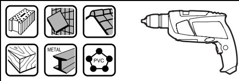
The machine is intended for impact drilling in brick, concrete and stone as well as for drilling in wood, metal and plastic. Machines with electronic control and right/left rotation are also suitable for screwdriving and thread-cutting.
Product Features
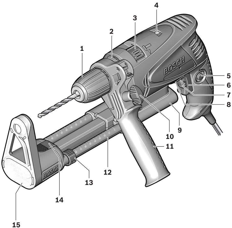
The numbering of the product features refers to the illustration of the machine on the graphics page.
1 Keyless chuck
2 Spindle lock button (PSB 600 RE/PSB 650 RE/PSB 650 RA)
3 "Drilling/Impact Drilling" selector switch
4 Rotation direction indicator (PSB 600 RE/PSB 650 RE/PSB 650 RA)
5 Lock-on button for On/Off switch
6 On/Off switch
7 Thumbwheel for speed preselection (PSB 600 RE/PSB 650 RE/PSB 650 RA)
8 Rotational direction switch
9 Extraction device with dust collector and depth stop
10 Wing bolt for adjustment of auxiliary handle
11 Auxiliary handle
12 Telescopic guide with depth stop scale
13 Set collar for depth stop
14 Release button for dust collector
15 Dust collector*
16 Dust protection ring
17 Locking latch für dust collector
18 Release button for extraction device
19 Filter element (micro filtersystem) *
20 Level indicator of the dust collector
21 Depth stop
22 Button for depth stop adjustment *
23 Universal bit holder
24 Screwdriver bit
25 Front sleeve
26 Rear sleeve
27 Allen key*
The accessories illustrated or described are not included as standard delivery.
*Commercially available (not included in the delivery scope)
Noise/Vibration Information
Measured values determined according to EN 60745.
Typically the A-weighted noise levels of the product are: Sound pressure level 97 dB(A); Sound power level 108 dB(A). Uncertainty K = 3 dB.
Wear hearing protection!
Vibration total values (triax vector sum) determined according to EN 60745:
Drilling into metal: Vibration emission value a_h = 4.7m / s^2 Uncertainty K = 1.5m / s^2
Impact drilling into concrete: Vibration emission value a_h = 24.2 m/s^2 , Uncertainty K = 2.0 m/s^2
Screwdriving: Vibration emission value a_h < 2.5 m/s^2 , Uncertainty K = 1.5 m/s^2 .
The vibration emission level given in this information sheet has been measured in accordance with a standardised test given in EN 60745 and may be used to compare one tool with another. It may be used for a preliminary assessment of exposure.
The declared vibration emission level represents the main applications of the tool. However if the tool is used for different applications, with different accessories or poorly maintained, the vibration emission may differ. This may significantly increase the exposure level over the total working period.
An estimation of the level of exposure to vibration should also take into account the times when the tool is switched off or when it is running but not actually doing the job. This may significantly reduce the exposure level over the total working period.
Identify additional safety measures to protect the operator from the effects of vibration such as: maintain the tool and the accessories, keep the hands warm, organisation of work patterns.
Technical Data
| Impact Drill | PSB 530 RA | PSB 600 RE | PSB 650 RE | PSB 650 RA | |
| Article number | 3 603 A26 1.. | 3 603 A26 2.. | 3 603 A26 2.. | 3 603 A26 2.. | |
| Rated power input | W | 530 | 600 | 650 | 650 |
| Output power | W | 263 | 320 | 338 | 348 |
| No-load speed | rpm | 50-3000 | 50-3000 | 50-3000 | 50-3000 |
| Rated speed | rpm | 2300 | 1900 | 1690 | 1690 |
| Impact rate | bpm | 48000 | 48000 | 48000 | 48000 |
| Rated torque | Nm | 1.0 | 1.5 | 1.9 | 1.9 |
| Torque at max. output power | Nm | 7.5 | 9.0 | 9.0 | 9.0 |
| Speed preselection | - | ● | ● | ● | |
| Right/left rotation | ● | ● | ● | ● | |
| Spindle lock | - | ● | ● | ● | |
| Dust extraction | ● | - | - | ● | |
| Spindle collar dia. | mm | 43 | 43 | 43 | 43 |
| Max. drilling dia. | |||||
| - Concrete | mm | 13 | 16 | 16 | 16 |
| - Steel | mm | 10 | 12 | 12 | 12 |
| - Wood | mm | 20 | 30 | 30 | 30 |
| - with extraction device mounted | mm | 13 | 13 | 13 | 13 |
| Chuck clamping range | mm | 2.0-13 | 2.0-13 | 2.0-13 | 2.0-13 |
| Weight according to EPTA-Procedure 01/2003 | |||||
| - with extraction device | kg | 1.6 | 1.7 | 1.7 | 1.7 |
| - without extraction device | kg | 1.5 | 1.6 | 1.6 | 1.6 |
| Protection class | ☐/II | ☐/II | ☐/II | ☐/II |
The values given are valid for nominal voltages [U] of 230/240 V. For lower voltage and models for specific countries, these values can vary.
Please observe the article number on the type plate of your machine. The trade names of the individual machines may vary.
Declaration of Conformity C
We declare under our sole responsibility that the product described under "Technical Data" is in conformity with the following standards or standardization documents: EN 60745 according to the provisions of the directives 2004/108/EC, 98/37/EC (until Dec. 28, 2009), 2006/42/EC (from Dec. 29, 2009 on).
Technical file at: Robert Bosch GmbH, PT/ESC, D-70745 Leinfelden-Echterdingen
Dr. Egbert Schneider Senior Vice President Engineering
Dr. Eckerhard Strötgen
Head of Product Certification

17.01.2008, Robert Bosch GmbH, Power Tools Division D-70745 Leinfelden-Echterdingen
Assembly
Before any work on the machine itself, pull the mains plug.
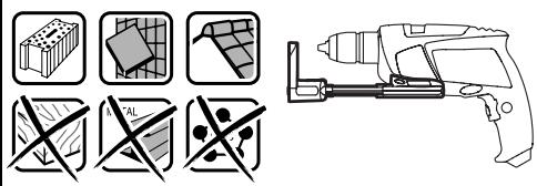
Dust/Chip Extraction (PSB 530 RA/ PSB 650 RA) (see figure A)
Dusts from materials such as lead-containing coatings, some wood types, minerals and metal can be harmful to one's health. Touching or breathing-in the dusts can cause allergic reactions and/or lead to respiratory infections of the user or bystanders. Certain dusts, such as oak or beech dust, are considered as carcinogenic, especially in connection with wood-treatment additives (chromate, wood preservative). Materials containing asbestos may only be worked by specialists.
- Use dust extraction whenever possible.
- Provide for good ventilation of the working place.
- It is recommended to wear a P2 filter-class respirator.
Observe the relevant regulations in your country for the materials to be worked.
- Use the dust/chip extraction only when working concrete, brick and brickwork. Wood or plastic chips can easily lead to clogging.
WARNING Fire hazard! Do not work metallic materials with the extraction device mounted. Hot metal chips can ignite parts of the extraction device.
To achieve optimum extraction results, please observe the following notes:
- Pay attention that the extraction device faces flush against the workpiece or the wall. This also makes drilling at a right angle easier.
- When using the extraction device, always work with the maximum speed.
After reaching the desired drilling depth, pull the drill bit out of the drill hole first and then switch off the impact drill. - Check the condition of the filter element 19 regularly. Replace a damaged filter element immediately.
- The dust protection ring 16 can wear, especially when working with large drill-bit diameters. Replace the dust protection ring when worn/damaged.
Mounting the Extraction Device
Guide the extraction device 9 from the front toward the bottom side of the impact drill. Pay attention that the extraction device 9 faces flush against the casing and that it is locked.
Cleaning the Extraction Device (see figure A)
Attach the locking latch 17 or empty the dust collector 15 before placing down the extraction device.
The dust collector 15 is sufficient for approx. 20 drillings with a drilling diameter of 6mm .
When the extraction force diminishes or when the level indicator 20 is full, the dust collector 15 must be emptied. For this, press on the riffled surface of the release button 14 and take off the dust collector 15.
Empty and clean the dust collector 15. Clean the filter element 19 by gently striking or tapping against it.
Check the filter element 19 for damage and replace it as required.
For this, as an example, pry off the holder of the filter element 19 (①) and change the filter element 19 including the holder (②). When placing on the holder again, make sure that the rubber gasket is inserted.
Reattach the dust collector 15 again and lock it by pressing against the smooth surface of the release button 14.
Removing the Extraction Device
For removal of the extraction device 9, push the release button 18 to the right or left and pull off the extraction device 9 toward the front.
Auxiliary Handle
Operate your machine only with the auxiliary handle 11.
The auxiliary handle 11 can be set to any position for a secure and low-fatigue working posture.
Turn the wing bolt for adjustment of the auxiliary handle 10 in anticlockwise direction and set the auxiliary handle 11 to the required position. Then tighten the wing bolt 10 again in clockwise direction.
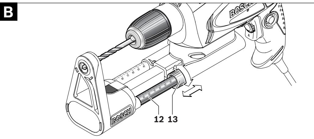
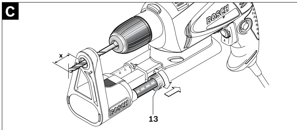
Adjusting the Drilling Depth (PSB 530 RA/PSB 650 RA) (see figure B-C)
With the extraction device mounted, the drilling depth "X" can be adjusted.
Insert a drill bit into the drill chuck and clamp the drill bit, see section "Changing the Tool", page 21. Rotate the collar for the depth stop 13 upward until it can be moved on the telescopic guide 12. Place the machine, without switching it on, firmly against the surface to be drilled until the drill bit touches the surface.
Read the scale value of the telescopic guide 12 on the collar 13. Add this value to the requested drilling depth X. Slide the collar 13 to the calculated scale value and then rotate the collar 13 downward to lock the determined clearance.
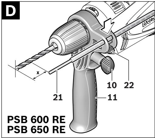
Adjusting the Drilling Depth (PSB 600 RE/PSB 650 RE) (see figure D)
The required drilling depth X can be set with the depth stop 21.
Press the button for the depth stop adjustment 22 and insert the depth stop into the auxiliary handle 11.
The knurled surface of the depth stop 21 must face upward.
Pull out the depth stop until the distance between the tip of the drill bit and the tip of the depth stop correspond with the desired drilling depth X .
Changing the Tool
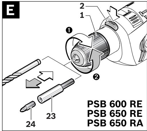
Keyless Chuck (PSB 600 RE/PSB 650 RE/PSB 650 RA) (see figure E)
The drill spindle is locked by pressing the spindle lock button 2. This makes quick and easy changing of the tool in the drill chuck possible.
Open the keyless chuck 1 by turning in rotation direction 0, until the tool can be inserted. Insert the tool.
Firmly tighten the collar of the keyless chuck 1 by hand in rotation direction 2 until the locking action ("click") is no longer heard. This automatically locks the chuck.
The locking is released again to remove the tool when the collar is turned in the opposite direction.
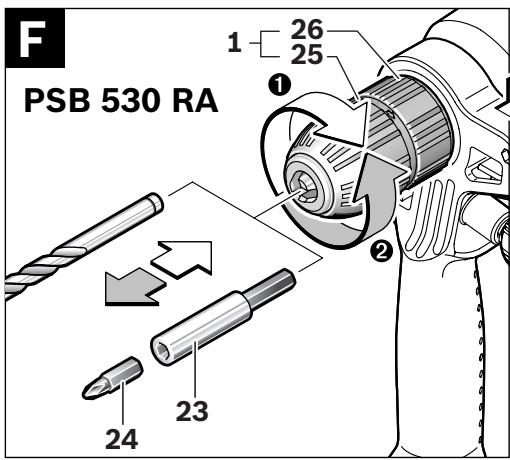
Keyless Chuck (PSB 530 RA) (see figure F)
Hold the rear sleeve 26 of the keyless chuck 1 tight and turn the front sleeve 25 in rotation direction 0, until the tool can be inserted. Insert the tool.
Hold the rear sleeve 26 of the keyless chuck 1 tight and firmly turn the front sleeve 25 in rotation direction ② by hand.
Screwdriver Tools
When working with screwdriver bits 24, a universal bit holder 23 should always be used. Use only screwdriver bits that fit the screw head.
For driving screws, always position the "Drilling/Impact Drilling" selector switch 3 to the "Drilling" symbol.
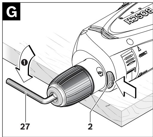
Replacing the Drill Chuck
For power tools without spindle lock, the drill chuck must be replaced by an authorised after-sales service agent for Bosch powder tools.
Removing the Drill Chuck (see figure G)
Clamp the short end of an Allen key 27 into the keyless chuck 1.
Place the machine on a firm surface, e. g. a workbench. Hold the machine firmly, press the spindle lock button 2 and loosen the keyless chuck 1 by turning the Allen key 27 in rotation direction ①. Loosen a tight keyless chuck by giving the long end of the Allen key 27 a light blow. Remove the Allen key from the keyless chuck and completely unscrew the keyless chuck.
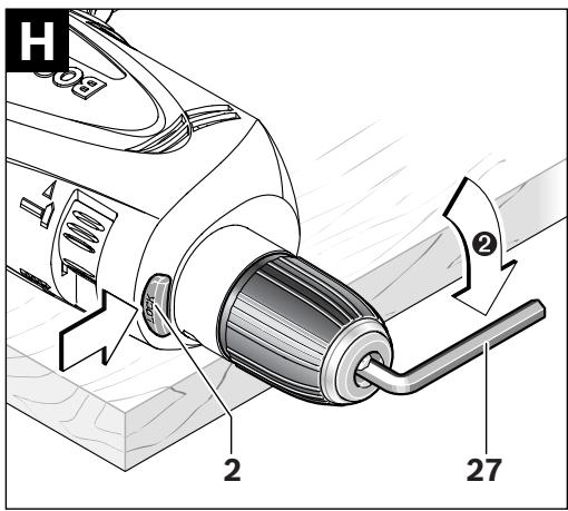
Mounting the Drill Chuck (see figure H)
The keyless chuck is mounted in reverse order.

The drill chuck must be tightened with a tightening torque of approx. 6-8 Nm.
Operation
Starting Operation
Observe correct mains voltage! The voltage of the power source must agree with the voltage specified on the nameplate of the machine. Power tools marked with 230V can also be operated with 220V .
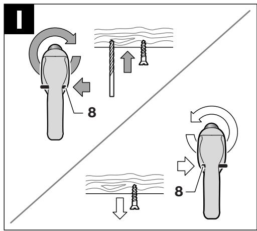
Reversing the Rotational Direction (see figure I)
The rotational direction switch 8 is used to reverse the rotational direction of the machine. However, this is not possible with the On/Off switch 6 actuated.
Right Rotation: For drilling and driving in screws, push the rotational direction switch 8 left to the stop.
PSB 600 RE/PSB 650 RE/PSB 650 RA: Rotation direction indicator 4 indicates the symbol “ ”.
Left Rotation: For loosening and unscrewing screws and nuts, press the rotational direction switch 8 through to the right stop.
PSB 600 RE/PSB 650 RE/PSB 650 RA: Rotation direction indicator 4 indicates the symbol “ ”.
Setting the Operating Mode

Drilling and Screwdriving
Set the selector switch 3 to the "Drilling" symbol.

Impact Drilling
Set the selector switch 3 to the "Impact drilling" symbol.
The selector switch 3 engages noticeably and can also be actuated with the machine running.
Switching On and Off
To start the machine, press the On/Off switch 6 and keep it depressed.
To lock the pressed On/Off switch 6, press the lock-on button 5.
To switch off the machine, release the On/Off switch 6 or when it is locked with the lock-on button 5, briefly press the On/Off switch 6 and then release it.
Adjusting the Speed/Impact Frequency
The speed/impact rate of the switched on power tool can be variably adjusted, depending on how far the On/Off switch 6 is pressed.
Light pressure on the On/Off switch 6 results in low speed/impact rate. Further pressure on the switch increases the speed/impact rate.
Preselecting the Speed/Impact Frequency (PSB 600 RE/PSB 650 RE/PSB 650 RA)
With the thumbwheel for speed preselection 7, the required speed/impact frequency can be preselected even during operation.
The required speed/impact frequency depends on the material and the working conditions, and can be determined through practical testing.
Working Advice
Apply the power tool to the screw/nut only when it is switched off. Rotating tool inserts can slip off.
After longer periods of working at low speed, allow the machine to cool down by running it for approx. 3 minutes at maximum speed with no load.
Maintenance and Service
Maintenance and Cleaning
Before any work on the machine itself, pull the mains plug.
For safe and proper working, always keep the machine and ventilation slots clean.
If the machine should fail despite the care taken in manufacturing and testing procedures, repair should be carried out by an after-sales service centre for Bosch power tools.
In all correspondence and spare parts order, please always include the 10-digit article number given on the type plate of the machine.
WARNING! Important instructions for connecting a new 3-pin plug to the 2-wire cable.
The wires in the cable are coloured according to the following code:
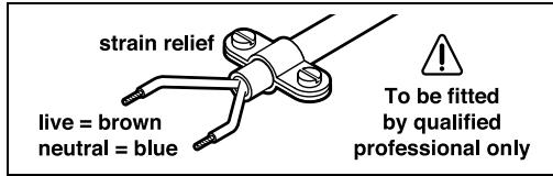
Do not connect the blue or brown wire to the earth terminal of the plug.
Important: If for any reason the moulded plug is removed from the cable of this power tool, it must be disposed of safely.
After-sales Service and Customer Assistance
Our after-sales service responds to your questions concerning maintenance and repair of your product as well as spare parts. Exploded views and information on spare parts can also be found under:
www.bosch-pt.com
Our customer consultants answer your questions concerning best buy, application and adjustment of products and accessories.
Great Britain
Robert Bosch Ltd. (B.S.C.)
P.O.Box 98
Broadwater Park
North Orbital Road
Denham
Uxbridge
UB 95HJ
Tel. Service: +44 (0844) 736 0109
Fax: +44 (0844) 736 0146
Australia, New Zealand and Pacific Islands
Robert Bosch Australia Pty. Ltd.
Power Tools
Locked Bag 66
Clayton South VIC 3169
Customer Contact Center
Inside Australia:
Phone: +61 (01300) 307 044
Fax: +61 (01300) 307 045
Inside New Zealand:
Phone: +64 (0800) 543 353
Fax: +64 (0800) 428 570
Outside AU and NZ:
Phone: +61 (03) 9541 5555
www.bosch.com.au
Disposal
The machine, accessories and packaging should be sorted for environmental-friendly recycling.
Only for EC countries:

Do not dispose of power tools into household waste!
According the European Guideline 2002/96/EC for Waste Electrical and Electronic Equipment and its implementation into national right,
power tools that are no longer usable must be collected separately and disposed of in an environmentally correct manner.
Subject to change without notice.
Dr. Egbert Schneider Senior Vice President Engineering
Dr. Eckerhard Strötgen
Head of Product Certification

17.01.2008, Robert Bosch GmbH, Power Tools Division D-70745 Leinfelden-Echterdingen
Montage
Robert Bosch (France) S.A.S.
Dr. Egbert Schneider Senior Vice President Engineering
Dr. Eckerhard Strötgen
Head of Product Certification

17.01.2008, Robert Bosch GmbH, Power Tools Division D-70745 Leinfelden-Echterdingen
Montaje
Dr. Egbert Schneider Senior Vice President Engineering
Dr. Eckerhard Strötgen
Head of Product Certification

i.v. Mojgcu
17.01.2008, Robert Bosch GmbH, Power Tools Division D-70745 Leinfelden-Echterdingen
Montagem
- Antes de todoseworkos na ferramenta electricadeferapeuxaraficha de rede da to-mada.
Dr. Egbert Schneider Senior Vice President Engineering
Dr. Eckerhard Strötgen
Head of Product Certification

i.v. Mojgcu
17.01.2008, Robert Bosch GmbH, Power Tools Division D-70745 Leinfelden-Echterdingen
Montaggio
Dr. Egbert Schneider Senior Vice President Engineering
Dr. Eckerhard Strötgen
Head of Product Certification

i.v. Moju
17.01.2008, Robert Bosch GmbH, Power Tools Division D-70745 Leinfelden-Echterdingen
Montage
Dr. Egbert Schneider Senior Vice President Engineering
Dr. Eckerhard Strötgen
Head of Product Certification

i.v. Mojgcu
17.01.2008, Robert Bosch GmbH, Power Tools Division D-70745 Leinfelden-Echterdingen
Montering
Bosch Service Center
Telegrafvej 3
2750 Ballerup
Tel. Service Center: +45 (04489) 8855
Fax: +45 (04489) 87 55
E-Mail: vaerktoej@dk.bosch.com
Bortskaffelse
El-vaerktoj, tilbehor og emballage skal genbruges pa en miljovenlig maje.
Dr. Egbert Schneider Senior Vice President Engineering
Dr. Eckerhard Strötgen
Head of Product Certification

17.01.2008, Robert Bosch GmbH, Power Tools Division D-70745 Leinfelden-Echterdingen
Montage
Dra stickproppen ur nätuttaget innan arbeiten utfors på elverktyget.
Damm-/spanutsugning (PSB 530 RA/PSB 650 RA) (se bild A)
Dr. Egbert Schneider Senior Vice President Engineering
Dr. Eckerhard Strötgen
Head of Product Certification

17.01.2008, Robert Bosch GmbH, Power Tools Division D-70745 Leinfelden-Echterdingen
Montering
Dr. Egbert Schneider Senior Vice President Engineering
Dr. Eckerhard Strötgen
Head of Product Certification

i.v. Moju
17.01.2008, Robert Bosch GmbH, Power Tools Division D-70745 Leinfelden-Echterdingen
Asennus
AiaβaTe oλeTic npo- eIbOonuTikEc unObeiEic.
Aeiec kata nTv thponTsw npoeiointikwv unodeiEewu npoei va npokaaleouv nektonla, kivduvo npkayiac h/kai obetaouc tpaumatioouc.
Dr. Egbert Schneider Senior Vice President Engineering
Dr. Eckerhard Strötgen
Head of Product Certification


17.01.2008, Robert Bosch GmbH, Power Tools Division D-70745 Leinfelden-Echterdingen
Euvaopoloyon
ByaZeTeTo ano Tnv npia npiv ano onoi- 6hnotepyaa oTo nAektpko epyaleio.
Avappoqn oKovnc/pokavldow (PSB 530 RA/PSB 650 RA) ( A)
H Okovn ano opioeva uliká. n.x. ano moluβ-δouxεc mnoviεc, ano εpika eibn Eulou, ano opukta uliká kai ano metaλλa mnopei va eivavavuyieivn. H enapn me tn okovn /kai n eiTnVOn TnC mnopei va npokaléoei aAlepYikec avtbpaeic n/kai aoheveic twv avanveu-otikw odov tou xpntn tuxov napepuoko-mevvw atoow.
Opiouva eioN oKovnc, n.x. oKovn ano Euloo
Belaivdiac n oxiac oewpuovtaiaavkapivoyova, 1dialtepa oe ouvduaouo me diapopa
ounnpomegaata kuaikau npaiopoiouvtai
otnv katepyaia xuaw (evwoecxpwuiou,
EluonpoatuteiKa eoa).H katepyaia
auiavouxwuvukw enipenetai mvo oe
eiknai6eueve aToja.
Sigmaoloyon tou took (Blambdaicova H)
H ouvapuoloyon tou taxutok yivetai akoIouthetavtac nTv avioTpoqn diaikajaia.

To took npenei va oipixei poin ouooyicn nepinou 6-8 Nm.
Aetroupyia
Ekkivnon
a n TnC nAeKtprkic nnyic npenei va tautietai me Tnv taon nou eival avaypaumevn otnv nivakida kataoakeuaotn tou nAeKtpiou epyaaleiou. Hkeptpka epyaiae i xapaktnpiotikn taon 230 V Leitoupyov ka e Taon 220 V.
Pouian oopac nepoiotpoqn (Blaene eikova I)
Me to diaokontn aalaync fopac nepiatoqphc 8
mnpoeite v' alaaetene popa nepiatoqphc tou
nlektipko epyaleiou. Auto, oomega, dev evai du
vató av o diaokontn ON/OFF 6 eivai natnuevoc.
KIVON: Tia To TpuTTma kai To Bldwa BiWv NaTnTo To diakontn aalaync Fopac nepiOTpOphc 8 tepa apotepa.
Tnpoume to 6ikaiwa aalayov.
Dr. Egbert Schneider Senior Vice President Engineering
Dr. Eckerhard Strötgen
Head of Product
Certification

i.v. Moju
17.01.2008, Robert Bosch GmbH, Power Tools Division
D-70745 Leinfelden-Echterdingen
Montaj
Bosch San. ve Tic. A.S.
Ahi Evran Cad. No:1 Kat:22
Polaris Plaza
80670 Maslak/Istanbul
Müsteri Danismani: +90 (0212) 335 06 66
Müsteri Servis Hatti: +90 (0212) 335 07 52