
PBH 160 RE - Rotary hammer BOSCH - Free user manual and instructions
Find the device manual for free PBH 160 RE BOSCH in PDF.
| Brand | BOSCH |
| Model | PBH 160 RE |
| Category | Rotary hammer (hammer drill) |
| Power input | 500 W |
| Impact rate | 0 – 4800 bpm |
| Impact energy | 1.3 J |
| No-load speed | 0 – 1100 rpm |
| Tool holder | SDS-plus |
| Max. drilling diameter (concrete) | 16 mm |
| Max. drilling diameter (wood) | 30 mm |
| Max. drilling diameter (steel) | 13 mm |
| Weight (according to EPTA 01/2003) | 2.0 kg |
| Protection class | II (double insulation) |
| Speed control | Yes (electronic variable speed) |
| Speed selection | Yes (preselection wheel) |
| Rotation direction reversal | Yes (right/left) |
| Constant rotation | Yes (lock button) |
| Additional handle | Yes (rotationally adjustable) |
| Depth stop | Yes (adjustable) |
| Dust protection cap | Yes (replaceable) |
| Maintenance | Clean ventilation slots and tool holder regularly |
| Included accessories | Additional handle, depth stop, 13 mm key chuck (depending on version) |
Frequently Asked Questions - PBH 160 RE BOSCH
User questions about PBH 160 RE BOSCH
0 question about this device. Answer the ones you know or ask your own.
Ask a new question about this device
Download the instructions for your Rotary hammer in PDF format for free! Find your manual PBH 160 RE - BOSCH and take your electronic device back in hand. On this page are published all the documents necessary for the use of your device. PBH 160 RE by BOSCH.
USER MANUAL PBH 160 RE BOSCH
Operating instructions
Senior Vice President
Engineering
Dr. Eckerhard Strötgen
Head of Product
Certification

Product Specifications
| Rotary Hammer | PBH 160 RE | PBH 180 RE PBH 1800 RE | PBH 200 RE | PBH 200 FRE | |
| Article number | 0 603 376 86. | 0 603 376 8.. | 0 603 376 7.. | 0 603 376 76. | |
| Exchangeable drill chuck | - | - | - | ● | |
| Speed control | ● | ● | ● | ● | |
| Speed preselection | ● | ● | ● | ● | |
| Right/Left rotation | ● | ● | ● | ● | |
| Rated input power | [W] | 500 | 510 | 530 | 550 |
| Impact rate | [per min] | 0 ... 4800 | 0 ... 4800 | 0 ... 4800 | 0 ... 4800 |
| Impact energy per stroke | [J] | 1.3 | 1.3 | 1.4 | 1.5 |
| Nominal speed | [RPM] | 0 ... 1100 | 0 ... 1100 | 0 ... 1100 | 0 ... 1100 |
| Tool holder SDS-plus | ● | ● | ● | ● | |
| Spindle collar diameter | [mm] | 43 (Euro-Standard) | 43 (Euro-Standard) | 43 (Euro-Standard) | 43 (Euro-Standard) |
| Maximum drill diameter: | |||||
| Concrete | [mm] | 16 | 18 | 20 | 20 |
| Wood | [mm] | 30 | 30 | 30 | 30 |
| Steel | [mm] | 13 | 13 | 13 | 13 |
| Weight in accordance with EPTA-Procedure 01/2003 | [kg] | 2.0 | 2.0 | 2.0 | 2.1 |
| Protection class | 回 / II | 回 / II | 回 / II | 回 / II | |
The specifications apply for the rated voltage of [U] 230/240 V. For lower voltages and with models for specific countries, the specifications can vary.
Please refer to the article number on the nameplate of your machine since the trade designation of individual machines can vary.
Noise/Vibration Information
Measured values determined according to EN 60745.
Typically, the A-weighted noise levels of the tool are:
Sound pressure level: 1, Sound power level: 2.
Measuring inaccuracy K = 3 dB.
Wear ear protection!
The typical weighted acceleration is ③.
| 1 | 2 | 3 | |
| PBH 160 RE | 85 dB(A) | 96 dB(A) | 9 m/s2 |
| PBH 180 RE | 85 dB(A) | 96 dB(A) | 9 m/s2 |
| PBH 1800 RE | 85 dB(A) | 96 dB(A) | 9 m/s2 |
| PBH 200 RE | 91 dB(A) | 102 dB(A) | 11 m/s2 |
| PBH 200 FRE | 91 dB(A) | 102 dB(A) | 11 m/s2 |
Intended Use
The machine is intended for hammer drilling in concrete, brick and stone. It is also suitable for drilling without impact in wood, metal, ceramic and plastic. Machines with electronic control and right/left rotation are also suitable for screw driving and thread cutting.
Product Elements
Please open the foldout page with the illustration of the tool and leave it open while you read these operating instructions.
The numbering of the machine elements refers to the illustration of the machine on the graphic page.
1 Ring gear exchangeable drill chuck, 13 mm
2 SDS-plus exchangeable drill chuck
3 Tool holder (SDS-plus)
4 Dust protection cap
5 Locking sleeve
6 Exchangeable drill chuck locking ring
7 Locking button
8 On/off switch
9 Speed control
10 Right/left rotation switch
11 Operational mode selection switch
12 Depth stop button
13 Auxiliary handle wing screw
14 Auxiliary handle
15 Depth stop
16 Drill chuck holder
17 Drill chuck
18 SDS-plus drill chuck shaft
19 Assembled drill chuck
20 SDS-plus adapter
21 Drill chuck key*
22 Depth stop scale value
- Not all the accessories illustrated or described are included in standard delivery.

For Your Safety
Read all instructions. Failure to follow all instructions listed below may result in electric shock, fire and/or serious injury.
SAVE THESE INSTRUCTIONS.
In addition, the general safety notes in the enclosed booklet must be observed.
Wear hearing protection. The noise can cause loss of hearing.
- Do not use the machine with a damaged cable. If the cable is damaged while working, do not touch the damaged cable but pull the mains plug. A damaged cable increases the risk of an electrical shock.
For machines used outdoors, connect to the mains using a fault current (FI) protection switch.
Use suitable detectors to find hidden utility lines or call the local utility company for assistance. Contact with electric lines can lead to fire or electrical shock. Damaging a gas line can result in an explosion. Penetrating a water pipe will cause property damage or an electrical shock.
Always use the auxiliary handle provided with the machine. The loss of control over the machine can result in injuries.
- Secure the work piece. A work piece clamped with clamping devices or in a vice is held more securely than by hand.
- Do not work with materials containing asbestos. Asbestos is considered carcinogenic.
Hold the machine firmly with both hands while working and provide for secure footing. The machine is more securely guided with both hands.
Wait until the machine has come to a standstill before placing it down. The insertion tool can become caught and lead to loss of control over the machine.
Changing the Drill Chuck (PBH 200 FRE)
The SDS-plus exchangeable drill chuck can easily be replaced on the rotary hammer with the ring gear exchangeable drill chuck provided.
Hammer drilling is possible only with SDS-plus tools that are inserted in the SDS-plus exchangeable drill chuck.
Drilling and screwdriving are also possible with tools without SDS-plus (e.g., round shaft drills, screwdriver bits) that are clamped in the ring gear exchangeable drill chuck.
Removing the Exchangeable Drill Chuck (Fig. A)
Danger of injury! Before removing the exchangeable drill chuck, always remove the tool or bit.
Grasp the locking ring 6 of the SDS-plus exchangeable drill chuck and pull forcefully in the direction of the arrow. The exchangeable drill chuck comes off.
Attaching the Exchangeable Drill Chuck (Fig. 3)
Take hold of the ring gear exchangeable drill chuck with the whole hand. Place it with a twisting motion on the chuck holder until it can clearly be heard to latch. The exchangeable drill chuck locks itself.
Check locking by pulling on the exchangeable drill chuck.
Make exchanges in the reverse order in a corresponding manner.
Maintenance of the Exchangeable Drill Chucks
Keep the connecting parts free of dust. Lubrication is not necessary.
Tool Changing (Fig. C-I)
Take care that the dust protection cap 4 is not damaged when changing tools.
SDS-plus Tools
The SDS-plus tool is designed to be freely movable. This causes eccentricity when the machine is off-load. However, the drill automatically centres itself during operation. This does not affect drilling precision.
Inserting (Fig. 6)
Clean and lightly oil the tool before inserting. Insert the dust-free tool into the tool holder 3 with twisting until it latches.
The tool locks itself. Check the locking by pulling on the tool.
Removing (Fig. D)
Pull the locking sleeve 5 to the rear (a) and hold while removing the tool (b).
Tools without SDS-plus
Do not use tools without SDS-plus for hammer drilling or chiselling!
PBH 160 RE/180 RE/1800 RE/200 RE
To work with tools without SDS-plus (e.g., drills with cylindrical shafts), a drill chuck 17 with a SDS-plus chuck shaft 18 (optional accessory) must be inserted into the tool holder (Fig. E).
Insert the dust-free, assembled chuck into the tool holder 3 with twisting until it latches (Fig. F).
The chuck locks itself. Check the locking by pulling on the chuck.
Srewdriver Bits (Fig. 6)
For screwdriver bits, use the SDS-plus adapter 20 (optional accessory).
PBH 200 FRE
Tool Insertion (Fig. H)
Turn the collar of the ring gear exchangeable drill chuck until the tool holder is opened wide enough. Insert the tool and clamp with the drill chuck key 21 uniformly in all three holes.
For screwdriver bits, insert a commercially available bit holder. Insert the screwdriver bits into the bit holder. Use only screwdriver bits that fit the screw heads. Screwdriver bits may also be inserted without a bit holder.
Tool Removal (Fig. 1)
To remove a tool from the ring gear exchangeable drill chuck, turn the collar in the direction of the arrow until the tool can be removed.
System Accessories
Refer to the Bosch Catalogue for insertion tools.
A list of accessories can be found at the end of these instructions.
Putting into Operation
Ensure that the mains voltage is correct!
The voltage of the power source must agree with the value given on the nameplate of the machine. Machines designated for 230V can also be operated with 220V .
Switching On/Off
To switch on the machine, press the on/off switch 8. Lock the depressed on/off switch 8 by pressing the lock-on button 7.
To switch off the machine, release the on/off switch 8 or press and then release it.
Working Instructions (Fig. K-N)
- Place the machine on the nut/screw only when it is switched off.
Auxiliary Handle (Fig. K)
For safety reasons, the machine should be used only with the auxiliary handle 14.
By rotating the auxiliary handle 14 to a comfortable position, a fatigue-free and therefore safe working position can be achieved.
Loosen the winged screw 13 on the auxiliary handle 14. Swing the grip to a new position. Retighten the winged screw.
Overload Clutch
If the insertion tool becomes caught or jammed, the drive to the drill spindle is interrupted. As a result of the forces that occur, always hold the machine firmly with both hands and provide for a sure footing.
Depth Stop (Fig. L)
With the depth stop 15, the drilling depth t can be set. Press the button 12 and pull out the depth stop to the tip of the drill. Read the value from the scale 22, subtract the desired drilling depth t and set the resulting value on the depth stop scale.
Dust Vacuuming/Vacuuming Attachment
Take protective measures when dust is produced while working that is detrimental to health, combustible or explosive. For example: Some dusts are considered to be carcinogenic. Use dust/chip extraction and wear a protective mask.
- Keep your workplace clean. Material mixtures are especially dangerous. Light metal dust can burn or explode.
The machine can be connected directly to the socket of a Bosch all-purpose vacuum cleaner with remote starting. The vacuum cleaner starts automatically when the machine is switched on.
Mount the vacuuming attachment (optional accessory) and connect the vacuum cleaner.
The vacuuming attachment is spring loaded up to the preselected drilling depth. In this manner, the vacuuming attachment head is always held close to the surface.
Setting the Speed (Fig. M)
By increasing or decreasing the pressure on the on/off switch 8, the speed can be continuously controlled during operation.
Advantages:
- Slow starting of holes, e.g., on smooth surfaces or tiles
- No sliding off of the drill when starting the hole
No splintering of the hole.
Speed Pre-Selection (Fig. N)
With the speed regulator 9, the required highest speed can be pre-set.
As a result of this limitation, the on/off switch can be pressed only to the pre-set highest speed.
The speed must be selected according to the operating mode, the material to be worked and the diameter of the drill.
See Operating Modes for recommended values.
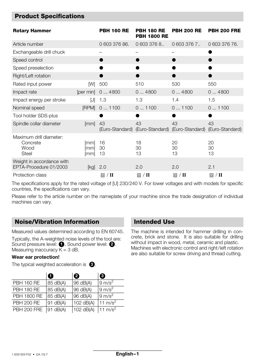
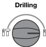
Operating Modes (Fig. O-S)
The operation of the gearbox for each application is set with the mode selection switch 11:
Hammer Drilling
The operating mode selector switch may be actuated only at a standstill.
Do not use tools without SDS-plus for hammer drilling or chiselling!
The following table shows how the operating mode selector switch 11, the right/left rotation switch 10 as well as the speed regulator 9 are to be set for the various operating modes (See fold-out page for figures):
| Operating Mode | Type PBH | |
| 160 RE/180 RE/1800 RE/200 RE | 200 FRE | |
| Hammer drilling in concrete or stone | Fig. ① | Fig. ① |
| Drilling in steel or wood | Fig. ① | Fig. ① |
| Screw driving | ||
| Right rotation | Fig. ① | Fig. ① |
| Left rotation | Fig. ① | Fig. ① |
| Chiselling only with MV 200 (optional accessory) | Fig. ① | - |
Maintenance and Cleaning
Before any work on the machine itself, pull the mains plug.
Always keep the machine and the ventilation slots clean for proper and safe working.
Clean the tool holder daily.
Replacing the Dust Protection Cap
Damaged dust protection caps should be replaced as soon as possible since dust that enters the tool holder can cause malfunctions.
It is recommended that this be performed by customer service.
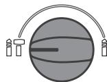
WARNING
Important instructions for connecting a new 3-pin plug to the 2-wire cable.
The wires in the cable are coloured according to the following code:
Do not connect the blue or brown wire to the earth terminal of the plug.
Important: If the plug on the cable of this machine must be replaced, dispose of the old plug to prevent misuse.
If the machine should fail despite the care taken in manufacture and testing, repair should be carried out by an authorised customer services agent for Bosch power-tools.
For all inquiries and replacement parts ordering, always include the 10-place article number on the nameplate of the machine.
Environmental Protection
Recycle raw materials instead of disposing as waste.
The machine, accessories and packaging should be submitted for environment-friendly recycling.
These instructions are printed on recycled paper manufactured without chlorine.
The plastic components are labelled for categorised recycling.
Service and Customer Advice
Exploded views and information on spare parts can be found under: www.bosch-pt.com.
Great Britain
Robert Bosch Ltd. (B.S.C.)
P.O.Box 98
Broadwater Park
North Orbital Road
Denham-Uxbridge
Middlesex UB 9 5HJ
Service +44 (0) 18 95/83 87 82
Advice line. +44 (0) 18 95/83 87 91
Fax +44 (0) 18 95/83 87 89
Ireland
Beaver Distribution Ltd.
Greenhills Road
Tallaght-Dublin 24
Service . 353 (0)1/414 9400
Fax 353 (0)1/459 8030
Australia
Robert Bosch Australia L.t.d.
RBAU/SBT2
1555 Centre Road
P.O. Box 66 Clayton
3168 Clayton/Victoria
+61 (0)1/800 804 777
Fax .+61 (0)1/800 819 520
www.bosch.com.au
E-Mail: CustomerSupportSPT@au.bosch.com
New Zealand
Robert Bosch Limited
14-16 Constellation Drive
Mairangi Bay
Auckland
New Zealand
+64 (0)9/47 86 158
Fax +64 (0)9/47 82 914
C Declaration of Conformity
We declare under our sole responsibility that this product is in conformity with the following standards or standardization documents:
EN 60745 according to the provisions of the directives 89/336/EEC, 98/37/EC.
Dr. Egbert Schneider
Senior Vice President
Engineering
Dr. Eckerhard Strötgen
Head of Product
Certification

Specifications subject to change without notice
\section*{Caracteristiques techniques}
Dr. Egbert Schneider Senior Vice President Engineering
Dr. Eckerhard Strötgen
Head of Product Certification
ppa. 1. i. n
Senior Vice President
Engineering
Dr. Eckerhard Strötgen
Head of Product
Certification

Senior Vice President
Engineering
Dr. Eckerhard Strötgen
Head of Product
Certification
ppa. Maee i.v. nye
Dr. Egbert Schneider Senior Vice President Engineering
Dr. Eckerhard Strötgen
Head of Product Certification
ppa. Maee i.v. nye
Dr. Egbert Schneider Senior Vice President Engineering
Dr. Eckerhard Strötgen
Head of Product Certification


Stovopsugning/Sugfix
Senior Vice President
Engineering
Dr. Eckerhard Strötgen
Head of Product
Certification
ppa. Maee i.v. nige
Dr. Egbert Schneider Senior Vice President Engineering
Dr. Eckerhard Strötgen
Head of Product Certification
ppa. Maee i.v. nige
Senior Vice President
Engineering
Dr. Eckerhard Strötgen
Head of Product
Certification


Senior Vice President
Engineering
Dr. Eckerhard Strötgen
Head of Product
Certification
ppa. Maee i.v. nige
KpatnoTe to daKTluo maVdaLwOnc 6 tou SDSplus took to xepi oac kaltpaBnEto foopaiau ^ ekvntou belouc.To took auve tal.
Tonoθετησιου tou took (εικόva B)
PiOTe to avtaaAxiMo ypavaZwTo Took m' oOkAnpo to xepiaoc. EioayTe To otnv unOboxn Tou ToOK nepiOtpeovtac To mexpi V' akouoTe otAoPaioe. To Took maVdaowvTea ano movo Tou.
EeYETn maVbaawon TpaBwTAC to Took.
Avaloya dEayetai kal n avtiotpoqn avtikata-otaon.
Euvtnpnon Tou Took
Aiatnpesite xwpic oKovcs ta ouvodetikαeepn. Ainavon ev eival anapaitntn.
Epyaia xwpi SDS-plus
Epyaεia xwpic SDS-plus npπεi va xpoaiopoiouvtai yia diatpnoan e kpuoan n yi aekuiieooic!
PBH 160 RE/180 RE/1800 RE/200 RE
Tia va unopoeetva epyaontte epyaiaxwpi cSDS-plus (π.x. trunavia kuivdpiko oEoxo), npenei va 10axtei otnv unooyn epyaiou eva took 17 unoooh SDS-plus 18 (eikó E).
EioayTe To xwpiocokovcTooK nepiotpfovtac To oTnv unoox npvaaleiou 3 expia va avadalwoe1 (EikoVA F).
To epyaIeio mavdaWvEi ano movo tou. EeYTe Tn mavdaawon meTpaBnyma tou epyaIeou.
Dr. Egbert Schneider Senior Vice President Engineering
Dr. Eckerhard Strötgen
Head of Product Certification

Devir sayisi on seciimi (Sekil N)
Bosch San. ve Tic. A.S.
Ahi Evran Cad. No:1 Kat:22
Polaris Plaza
80670 Maslak/Istanbul
0 90 (0)212/335 06 00
Faks .+90 (0)212/346 00 48-49
CE Uygunluk beyani
Senior Vice President
Engineering
Dr. Eckerhard Strötgen
Head of Product
Certification
ppa. 1. n.