
WHMHF09G3E8 - Heat pump PANASONIC - Free user manual and instructions
Find the device manual for free WHMHF09G3E8 PANASONIC in PDF.
| Product type | Monobloc air-to-water heat pump |
| Brand | Panasonic |
| Model | WHMHF09G3E8 |
| Power supply | Single-phase, 230 V ~ 50 Hz |
| Sound pressure (approximate) | 46 dB(A) (silent mode) |
| Water outlet temperature (heating) | 25 °C to 65 °C |
| Outdoor ambient temperature (heating) | -20 °C to 35 °C |
| Backup heater | Built-in, adjustable power from 3 to 9 kW |
| Operating modes | Heating, domestic hot water, vacation, weekly timer |
| Refrigerant | R32 (typical for this type of device) |
| Frost protection | Yes, built-in |
| Tank sterilization function | Yes, adjustable up to 75 °C |
| Regular maintenance | Clean external filter once a year |
| Weight (outdoor unit) | Approximately 65 kg (estimated) |
| Dimensions (outdoor unit, W x H x D) | Approximately 800 x 600 x 300 mm (estimated) |
| Safety | Residual current circuit breaker (RCCB), mandatory grounding |
| Spare parts | Available from Panasonic authorized service |
| Warranty | See warranty terms provided with the device |
Frequently Asked Questions - WHMHF09G3E8 PANASONIC
User questions about WHMHF09G3E8 PANASONIC
0 question about this device. Answer the ones you know or ask your own.
Ask a new question about this device
Download the instructions for your Heat pump in PDF format for free! Find your manual WHMHF09G3E8 - PANASONIC and take your electronic device back in hand. On this page are published all the documents necessary for the use of your device. WHMHF09G3E8 by PANASONIC.
USER MANUAL WHMHF09G3E8 PANASONIC
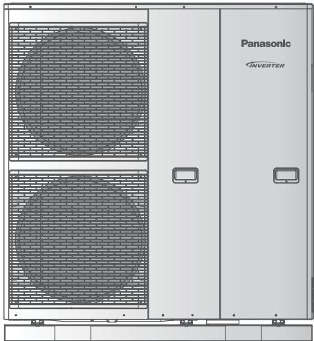
Operating Instructions
(Mono bloc) Air-to-Water Heatpump
Model No.
Mono bloc Unit
WH-MHF09G3E8
WH-MHF12G9E8

Operating Instructions (Mono logs) Air to Water Heat pump 2-15
Installation Instructions attached.
Thank you for purchasing Panasonic product.
Before operating the system, read these operating instructions thoroughly and keep them for future reference.
Table of contents
Safety precautions 3-5
To adjust initial settings 6-7
How to use 8-12
Maintenance 12
Troubleshooting 13-14
Information 15

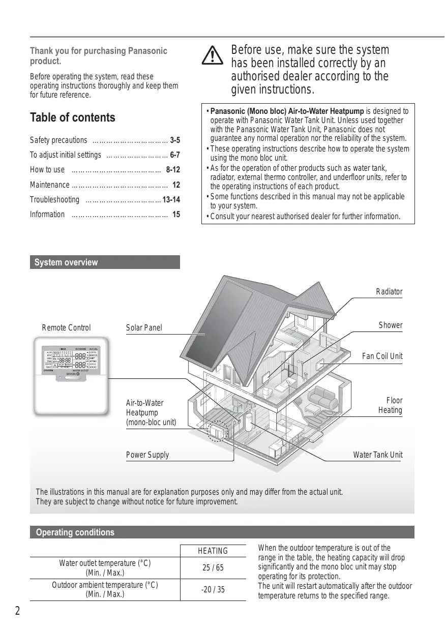
Before use, make sure the system has been installed correctly by an authorised dealer according to the given instructions.
- Panasonic (Mono bloc) Air-to-Water Heatpump is designed to operate with Panasonic Water Tank Unit. Unless used together with the Panasonic Water Tank Unit, Panasonic does not guarantee any normal operation nor the reliability of the system.
- These operating instructions describe how to operate the system using the mono bloc unit.
- As for the operation of other products such as water tank, radiator, external thermo controller, and underfloor units, refer to the operating instructions of each product.
- Some functions described in this manual may not be applicable to your system.
- Consult your nearest authorised dealer for further information.
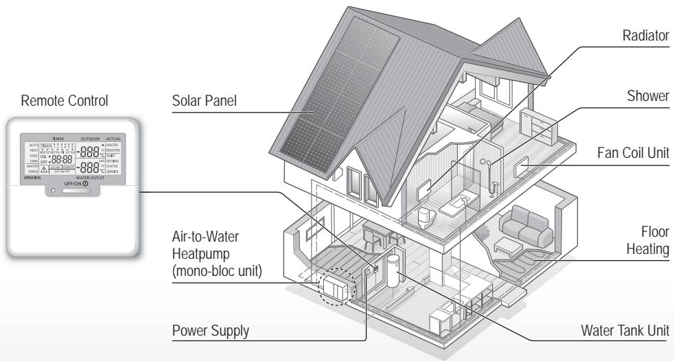
System overview
The illustrations in this manual are for explanation purposes only and may differ from the actual unit.
They are subject to change without notice for future improvement.
Operating conditions
| HEATING | |
| Water outlet temperature (°C) (Min. / Max.) | 25 / 65 |
| Outdoor ambient temperature (°C) (Min. / Max.) | -20 / 35 |
When the outdoor temperature is out of the range in the table, the heating capacity will drop significantly and the mono bloc unit may stop operating for its protection.
The unit will restart automatically after the outdoor temperature returns to the specified range.
Safety precautions
To prevent personal injury, injury to others or property damage, please comply with the following: Incorrect operation due to failure to follow instructions below may cause harm or damage, the seriousness of which is classified as below:
| WARNING | This sign warns of death or serious injury. |
| CAUTION | This sign warns of injury or damage to property. |
The instructions to be followed are classified by the following symbols:
| This symbol denotes an action that is PROHIBITED. |
| These symbols denote actions COMPULSORY. |

WARNING
Mono bloc unit

This appliance may be used by children aged from 8 years and above and persons with reduced physical, sensory or mental capabilities or lack of experience and knowledge if they have been given supervision or instruction concerning use of the appliance in a safe way and understand the hazards involved. Children shall not play with the appliance. Cleaning and user maintenance shall not be made by children without supervision.
Please consult an authorised dealer or specialist to clean the internal parts, repair, install, remove and reinstall the unit. Improper installation and handling will cause leakage, electric shock or fire.
Confirm with an authorised dealer or specialist on usage of any specified refrigerant type. Using refrigerant type other than the specified may cause product damage, burst and injury etc.

Do not install the unit in a potentially explosive or flammable atmosphere. Failure to do so could result in fire.
Do not insert your fingers or other objects into the mono bloc unit; the rotating parts may cause injury.


Do not touch the mono bloc unit during lightning, it may cause an electric shock.
Do not sit or step on the unit, you may fall down accidentally.

Power supply

Do not use a modified cord, joint cord, extension cord or unspecified cord to prevent overheating and fire.


To prevent overheating, fire or electric shock:
- Do not share the same power outlet with other equipment.
- Do not operate with wet hands.
- Do not bend or twist power supply cord.

If the supply cord is damaged, it must be replaced by the manufacturer, service agent or similarly qualified persons in order to avoid a hazard.
This unit is equipped with Residue Current Circuit Breaker (RCCB). Ask an authorised dealer to check RCCB operation regularly, especially after installation, inspection, and maintenance. RCCB malfunction may result in electric shock and/ or fire.
It is strongly recommended that Install Residual Current Device (RCD) on-site to prevent electric shock and/or fire.

Before obtaining access to terminals, all supply circuits must be disconnected.
Stop using the product if any abnormality/failure occurs and disconnect the power supply. (Risk of smoke/fire/electric shock)
Examples of abnormality/failure
RCCB trips frequently.
- Burning smell is observed.
- Abnormal noise or vibration of the unit is observed.
- Hot water leaks from the unit. Contact your local dealer immediately for maintenance/ repair.
Wear gloves during inspection and maintenance.

This equipment must be earthed to prevent electrical shock or fire.

Prevent electric shock by disconnecting the power supply before cleaning or servicing.
This appliance is for multiple uses. To avoid electric shock, burn and/or fatal injury, make sure to disconnect all power supplies before accessing any terminal in the unit.

CAUTION
Mono bloc unit

Do not wash the unit with water, benzine, thinner or scouring powder to avoid damage or corrosion on the unit.
Do not install the unit close to any combustibles or at bathroom. Otherwise, it may cause electric shock and/or fire.
Do not touch the water discharge pipe of the unit during operation.
Do not place any material on the unit or under it.
Do not touch the sharp aluminium fin; sharp parts may cause injury.

Do not use the system during sterilisation in order to prevent scalding with hot water, or overheating of shower.

Prevent water leakage by ensuring that the drainage pipe is connected properly.
After a long period of use, make sure the installation rack is not deteriorated. The deteriorated rack may cause the unit to fall down.
Ask an authorised dealer to determine the level of sterilisation function field settings according to the local laws and regulations.
Remote control

Do not wet the remote control. Failure to do so may result in electric shock and/or fire.
Do not press the buttons on the remote control using hard and sharp objects. Failure to do so may cause damage to the unit.
Do not wash the remote control using water, benzine, thinner or scouring powder.
Do not inspect or maintain the remote control by yourself. Consult an authorised dealer in order to prevent personal injury caused by incorrect operation.
Dealer
Select menus and determine settings according to the system available in the household. It is recommended that all alterations of settings are done by an authorised dealer or specialist.
- After initial installation, you may manually adjust the settings. The initial setting remains active until the user changes it.
- The remote control can be used for multiple installations.
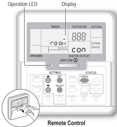
- Ensure the operation LED is OFF before setting.
- The system may not work properly if set wrongly. Please consult an authorised dealer.
① Press SET and CHECK simultaneously and hold for 5 seconds until the display shows SETTING STATUS.
② Press or to select the menu.
(3) Press SELECT to enter the menu.
4 Press or to select YES/NO, or other options. YES: to enable the menu NO: to disable the menu
⑤ Press SET to confirm.
| Menu (1 ~ 17) | Default Setting | Setting | Display | ||
| 1 | Room Thermostat Connection To select whether or not to connect to the optional room thermostat. | NO | YES | NO | ro a' con |
| 2 | Backup Heater Selection To reduce the heater power if unnecessary. *Options of kW vary depending on the model. | 9 kW | *3 kW / 6 kW / 9 kW | HEATER CAP | |
| 3 | Water System Freeze Prevention To activate or deactivate the water freeze prevention when the system is OFF. | YES | YES | NO | Rnt, FrE |
| 4 | Tank Connection To select whether or not to connect to the optional water tank unit. Note: If NO is selected, menus 5 to 15 are skipped. | NO | YES | NO | TANK con |
| 5 | Solar Priority To select the use of solar panel for heating up the water tank. | NO | YES | NO | SOLAR Priy |
| 6 | Heating Priority To select the room heating as priority during HEAT + TANK mode. Note: If YES is selected, menus 7 and 8 are skipped for HEAT + TANK mode. | NO | YES | NO | HEAT Priy |
| 7 | Heating Operation Interval To set the interval for HEAT mode during HEAT + TANK mode. Note: If YES is selected in menu 6, this menu is skipped. | 3 hours | 0.5 hours ~ 10 hours | HEAT int | |
| 8 | Tank Heat-up Interval To set the interval for the water tank during HEAT + TANK mode. Note: If YES is selected in menu 6, this menu is skipped. | 30 minutes | 5 minutes ~ 1 hour 35 minutes | TANK int | |
| 9 Booster Heater To activate or deactivate the water tank's booster heater. Note: If NO is selected, menu 10 is skipped. | YES | YES | NO | BOOSTER | Fun |
| 10 Booster Heater Delay Timer To delay time for the booster heater to activate while the system is heating up the water tank. | 1 hour | 20 minutes ~ 1 hour 35 minutes | BOOSTER | dLY | |
| ·Do not use the system during sterilisation in order to prevent scalding with hot water, or overheating of shower. ·Ask an authorised dealer to determine the level of sterilisation function field settings according to the local laws and regulations. | |||||
| 11 Sterilisation To sterilise the water tank, if required. Note: If NO is selected, menus 12 to 14 are skipped. | YES | YES | NO | St rL | Fun |
| 12 Sterilisation Day & Time To set timer for sterilisation. (Only once a week. Operates even under a standby condition) | Monday 12:00 | Monday ~ Sunday 0:00 ~ 23:50 | Str | ||
| 13 Sterilisation Temperature To set the temperature of sterilisation. | 70 °C | 40 °C ~ 75 °C | St rL | bo l | |
| 14 Continuation of Sterilisation To maintain heating temperature in order to complete the sterilisation. | 10 minutes | 5 minutes ~ 1 hour | Str | aPr | |
| 15 Base Pan Heater To select whether or not to connect to the optional base pan heater. Note: If NO is selected, menu 16 is skipped. | NO | YES | NO | bP An | htr |
| 16 Base Pan Heater type Type A - The base pan heater activates only during deice operation. Type B - The base pan heater activates when outdoor ambient temperature is 5 °C or lower. | A | A | B | bP An | htr |
| 17 Dry Concrete During construction to dry the concrete under a preset temperature. Do not use this menu for any other purposes and in period other than during construction (Refer to information page). | - | 1 day ~ 99 days | dr y | Con | |
User
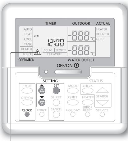
Remote control preparation
① Press CLOCK
② Press or to set the current day.
③ Press to confirm.
④ Repeat steps ② and ③ to set the current time.
Note:
- The current day and time need to be set in cases below:
- When the power is turned on for the first time.
- A long time has elapsed since the power was turned on the last time.
- The current time that has been set will be the standard time for all the timer operations.
Caution Indicator (Tank Temperature above 60^ )
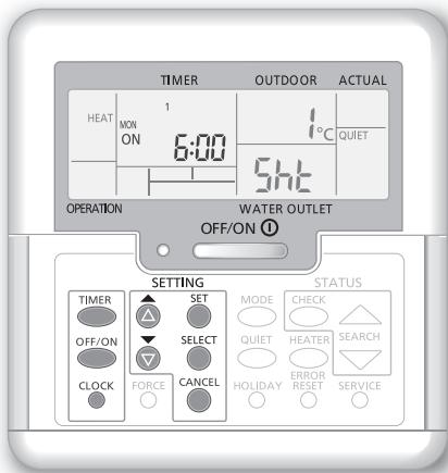
User
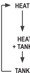
Turn on or off the system
When the system is ON, the operation LED is lit and the actual water outlet temperature and outdoor ambient temperature are shown on the display.
User
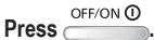
Select operation mode
Press to select operation mode.
- The panel/floor HEAT operation is either turned ON or OFF.
- The mono bloc unit provides heat to the system.
- The mono bloc unit provides heat to the sanitary water tank and the system.
- This mode can be selected only when the sanitary water tank is installed.
- The sanitary water tank is either turned ON or OFF.
- The mono bloc unit provides heat to the sanitary water tank.
User
Initiate the backup heater

- The backup heater provides extra heat at low outdoor temperature. The backup heater is possible only in the heat mode.
- Once the backup heater is set, it is automatically operated when conditions are fulfilled.
To disable the backup heater, press HEATER again.
The system is turned off by an external switch.
User
Enjoy quiet operation

- This operation reduces the noise of mono bloc unit. The operation may cause heating ability to decrease.
User
System status check mode
① Press CHECK.
(The display shows STATUS.)
② Press or to check the selected mode.
- Dry concrete (does not show during normal operation)
The Water Inlet Temperature
Tank Temperature - Compressor Running Frequency
- Error History
- Heat mode total power consumption (Up to 999 days)
Tank mode total power consumption (Up to 999 days) CHECK - Press to exit the STATUS mode.
Note:
- Once the STATUS mode is entered, the display shows STATUS.
- The STATUS mode cannot be activated when the display shows SETTING.
- The total power consumption is an estimated value based on AC 230 V and may differ from value measured by precise equipment.
Dealer
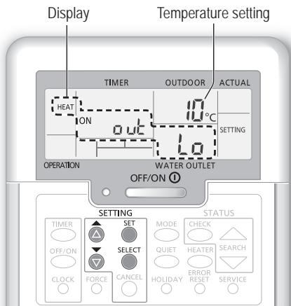
System temperature setting
The system controls the temperature for each menu based on the outdoor ambient temperature.
- To set or change the temperatures, make sure to contact your nearest authorised dealer.
① Press and hold SET for 5 seconds to enter the temperature range setting mode. (The display shows SETTING.)
② Press or to select a menu.
③ Press SELECT to enter the menu.
④ Press or to set the desired temperature.
⑤ Press SET to confirm the setting.
- Repeat steps ② to ⑤ to set other menus.
User
Checking the temperature range
① Press and hold for 5 seconds to enter the temperature range setting mode.
② Press or to select a menu.
Press CANCEL to exit.
| Menu | Default setting | Temperature setting | Display | |
| Setting of low outdoor ambient temperature. | -5 °C | -15 °C ~ 15 °C | HEAT | ON out Lo |
| Setting of high outdoor ambient temperature. | 15 °C | -15 °C ~ 15 °C | ON out Hi | |
| Setting of water outlet temperature at low outdoor ambient temperature. | 55 °C | 25 °C ~ 65 °C | ON H20 Lo | |
| Setting of water outlet temperature at high outdoor ambient temperature. | 35 °C | 25 °C ~ 65 °C | ON H20 Hi | |
| During HEAT mode, the water outlet temperature is adjusted as <Water outlet temperature> max. water temp. min. water temp. It is shown the diagram on the right. It is performed within the preset temperature range. | ||||
| Setting of outdoor ambient temperature to turn OFF heating operation during HEAT mode. | 24 °C | 5 °C ~ 35 °C | HEAT | OFF SET |
| Setting of outdoor ambient temperature to turn ON the backup heater. | 0 °C | -15 °C ~ 20 °C | HEATER | ON OUT SET |
| Setting of sanitary water tank temperature. | 52 °C | 40 °C ~ 75 °C | TANK | SET |
User
Shifting the water temperature
This easily shifts the water outlet temperature if the setting is undesirable.
① Press SET to enter the water temperature shifting mode.
② Press SELECT to change setting.
③ Press or to set the desired temperature. (temperature range: -5^ 5^
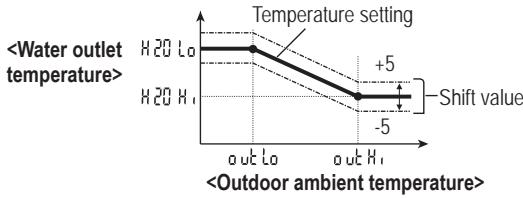
Desired temperature setting
4 Press SET to confirm the setting.
Note:
- Press or wait for 30 seconds to exit the SETTING mode.
- The set temperature will be saved in the system once confirmed.
- The SETTING mode cannot be activated when the SERVICE and STATUS indicators are ON.
- The system will shift the temperature within water outlet temperature range.
User
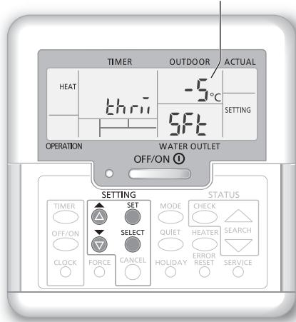
Holiday mode
- By setting the day (s) in holiday mode, it promotes energy saving while you are on holiday, and enables the system to resume at the preset temperature after your holiday.
- Ensure that the system is OFF before setting.
- The system will resume operation automatically at 00:00 am after the holiday.
- The day the HOLIDAY mode was set is counted as day 1.
Example:
Setting the holiday mode on June 21, 08:00 am. By setting 3 days, the system resumes operation on June 24, 00:00 am.
① Press HOLIDAY to enter the HOLIDAY mode.
② Press or to set the desired days. (Setting range: 1 day 999 days)
③ Press SET to confirm the setting.
Note:
Press CANCEL or wait 30 seconds to exit the HOLIDAY mode.
User
Weekly timer setting
Promotes energy saving by allowing you to set up to 6 programmes in any given day.
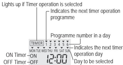
① Press to enter the timer setting mode.
② Press or to select your desired day.
③ Press SELECT to confirm your selection.
④ “1” will be blinking, press SELECT to set programme 1.
⑤ Press OFF/ON to select ON or OFF timer.
Press or to select your desired time. MODE QUIT HEATER You can set, , and the Water Temperature Thermo Shift setting.
⑦ Press to confirm programme 1. The selected day will be highlighted with .
After 2 seconds, the display will move to the next programme. Repeat steps ④ to ⑦ to set programmes 2 to 6.
- During timer setup, if no button is pressed within 30 seconds, or if the is pressed, the setting at that moment is confirmed and timer setup is ended.
To check current timer programme
① Press TIMER to enter timer mode and press SELECT to enter day setting.
② Press or until your desired day is shown, press to confirm your selection.
③ Press or to check the set programmes.
To modify current timer programme or add new timer programme
① Perform steps ① to ⑦ of “Weekly timer setting” to modify existing timer programme, or add any timer programme.
To cancel current timer programme
① Press SELECT to enter day.
② Press or until your desired day is shown, press to enter programme setting.
③ Press or until your desired programme is shown. Press to cancel the programme and will disappear.
To disable/enable Weekly Timer
To disable weekly timer setting, press , then press CANCEL
To enable previous weekly timer setting, press TIMER then press SET
Weekly timer setting
Note:
- You may set the timer for each day of the week (Monday to Sunday) with 6 programmes per day.
- When the system is switched on by the timer, it will use the previously set temperature to control the water outlet temperature.
- The same timer programme cannot be set on the same day.
- You may also select 2 or more days with the same timer setting.
Maintenance
Mono bloc Unit
In case of a power supply failure or pump operating failure, drain the system (as suggested in the figure below).
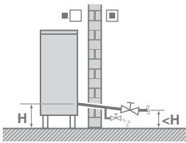
When water is idle inside the system, freezing up is very likely to happen which could damage the system.
- Do not obstruct the air inlet and air outlet vents, it may cause low performance or breakdown. Please remove obstacles to assure the ventilation.
- During winter, please clean and remove the snow near mono bloc unit so that the snow does not cover the air inlet and air outlet vents.
External filter
- Clean the external filter at least once a year. Failure to do so may cause the filter to clog up, which may lead to system breakdown. Consult an authorised dealer.
Inspection
- In order to ensure optimal performance of the units, seasonal inspections on the units, external filter and field wiring have to be carried out at regular intervals. Consult an authorised dealer about maintenance.
- Clear any obstruction on the air inlet and outlet vents of the mono bloc unit.

For extended non-use
- Do not switch off the power supply. Switching off the power supply will stop the automatic water pump operation and will cause jamming in the water pump.
Non serviceable criteria
Disconnect the power supply
then please consult an authorised dealer under the following conditions:
Abnormal noise during operation.
Water/foreign particles have entered the remote control.
- Circuit breaker switches off frequently.
- Power cord becomes unnaturally warm.
The following symptoms do not indicate malfunction.
| Symptom | Cause |
| Water flowing sound during operation. | · Refrigerant flow inside the unit. |
| Operation is delayed a few minutes after restarting. | · The delay is a protection for the compressor. |
| Mono bloc unit emits water/steam. | · Condensation or evaporation occurring in the pipes. |
| Steam comes out of the mono bloc unit in the heating mode. | · It is caused by defrost operation in the heat exchanger. |
| Mono bloc unit does not operate. | · It is caused by the protection control of the system when outdoor temperature is out of the operating range. |
| System operation switches off. | · It is caused by the protection control of the system. When the water inlet temperature is lower than 10 °C, the compressor stops and the backup heater power turns on. |
| System is hard to heat up. | · When the panel and the floor are heated simultaneously, warm water temperature may decrease, which may reduce the heating ability of the system. · When the outdoor air temperature is low, the system may need longer time to heat up. · Discharge outlet or intake inlet in the mono bloc unit is blocked by some obstacle, such as a pile of snow. · When the preset water outlet temperature is low, the system may need longer time to heat up. |
| System does not heat up instantly. | · System will take some time to heat up the water if it starts to operate at cold water temperature. |
| Backup heater is automatically turned ON when it is disabled. | · It is caused by the protection control of the unit heat exchanger. |
| Operation starts automatically when the timer is not set. | · Sterilisation timer has been set. |
| Display power consumption remains as previous value. | · Memory is saved on hourly basis. If a power failure occurs, the data kept from last hour will be displayed. · Total power consumption has reached 999 days. Press CANCEL to reset the counter. |
| HEAT indicator blinks on the display. | · System is performing deice operation. |
| Loud refrigerant noise continue for a few minutes. | · It is caused by protection control during deice operation at outdoor ambient temperature lower than -10°C. |
Check the following before calling for servicing.
| Symptom | Check |
| Operation in HEAT mode is not working efficiently. | ·Set the temperature correctly. ·Close the panel heater valve. ·Clear any obstruction in the air inlet and air outlet vents of the mono bloc unit. |
| Noisy during operation. | ·Mono bloc unit has been installed at an incline. ·Close the cover properly. |
| System does not work. | ·Circuit breaker has tripped/activated. |
| Operation LED is not lit or nothing is displayed on the remote control. | ·Check that the power supply is working correctly, or that a power failure has not occurred. |
Force Heater Mode Button
FORCE
- If a malfunction occurs in the system, the backup heater may be used to heat up the water.
Press FORCE to switch on the backup heater.
OFF/ON ①
- Press to switch off the backup heater.
- In the Force Heater mode, no other operation can be used.
- This feature is only available to certain error codes.
Refer to dealer for more details.
The operation LED blinks and error code appears on the display.
| TIMER | · Disconnect the power supply, and report the error code to an authorised dealer. · The timer operation will be cancelled when an error code is displayed. |
| Diagnostic display | Abnormality or Protection control works |
| H12 | Capacity mismatch |
| H15 | Abnormal compressor temperature sensor |
| H20 | Abnormal water pump |
| H23 | Abnormal refrigerant 1 sensor |
| H27 | Abnormal service valve |
| H42 | Compressor low pressure protection |
| H62 | Abnormal water flow |
| H63 | Abnormal low pressure sensor |
| H64 | Abnormal high pressure sensor |
| H65 | Abnormal deice water circulation |
| H70 | Abnormal back-up heater overload protector |
| H72 | Abnormal tank temperature sensor |
| H76 | Remote control communication error |
| H90 | Abnormal indoor / outdoor communication |
| H91 | Abnormal tank heater overload protector |
| H95 | Abnormal voltage connection |
| H98 | Outdoor high pressure protection |
| H99 | Indoor heat exchanger freeze prevention |
| Diagnostic display | Abnormality or Protection control works |
| F12 | Pressure switch activated |
| F14 | Poor compressor rotation |
| F15 | Abnormal outdoor fan motor lock |
| F16 | Comprehensive current protection |
| F20 | Compressor temperature overload protection |
| F22 | Transistor module temperature overload protection |
| F23 | DC peak abnormal of operation |
| F24 | Abnormal Refrigerant cycle |
| F25 | Abnormal in a cooling / heating charge |
| F27 | Abnormal pressure switch |
| F30 | Abnormal water outlet sensor 2 |
| F36 | Abnormal outdoor air temperature sensor |
| F37 | Abnormal water inlet sensor |
| F40 | Abnormal outdoor discharge sensor |
| F41 | Abnormal power factor correction |
| F42 | Abnormal outdoor heat exchanger sensor |
| F43 | Abnormal outdoor defrost sensor |
| F45 | Abnormal water outlet sensor |
| F46 | Abnormalities in outdoor current transformer disconnection |
| F48 | Abnormal evaporator outlet temperature sensor |
| F49 | Abnormal bypass outlet temperature sensor |
| F95 | Abnormal cooling high pressure |
Information for Users on Collection and Disposal of Old Equipment
These symbols on the products, packaging, and/or accompanying documents mean that used electrical and electronic products should not be mixed with general household waste.
For proper treatment, recovery and recycling of old products, please take them to applicable collection points, in accordance with your national legislation and the Directives 2002/96/EC and 2006/66/EC.
By disposing of these products correctly, you will help to save valuable resources and prevent any potential negative effects on human health and the environment which could otherwise arise from inappropriate waste handling.
For more information about collection and recycling of old products, please contact your local municipality, your waste disposal service or the point of sale where you purchased the items.
Penalties may be applicable for incorrect disposal of this waste, in accordance with national legislation.

For business users in the European Union
If you wish to discard electrical and electronic equipment, please contact your dealer or supplier for further information.
[Information on Disposal in other Countries outside the European Union]
These symbols are only valid in the European Union. If you wish to discard these items, please contact your local authorities or dealer and ask for the correct method of disposal.
Operation/settings to be done only by the authorised dealer/specialist.
Dry Concrete Function
- During construction to dry the concrete under a preset temperature.
① Press SET and CHECK simultaneously and hold for 5 seconds until the display shows "ra oit con".
② Press. (The display shows "dr Y [con].)
SELECT ③ Press to select day. Press or to set the desired temperature.
④ Press SET to confirm the selection.
⑤ Repeat step ③ and ④ to set other days and temperature.
Press CANCEL to exit.
To Reset the Remote Control to Default Setting
① Press , , continuously for 5 seconds. The operation is off during this period.
The display shows "dF Lc, dRc, dnE" for 2 seconds for confirmation. After 2 seconds, it goes to normal display.

© Panasonic Corporation 2015