
S80MW1E5 - Heat pump PANASONIC - Free user manual and instructions
Find the device manual for free S80MW1E5 PANASONIC in PDF.
| Brand | Panasonic |
| Model | S80MW1E5 |
| Product type | Commercial hydraulic heat pump |
| Refrigerant | R410A (GWP 1975) |
| Main functions | Cooling, heating, maintenance, tank mode |
| Water temperature range (cooling) | 5 °C to 20 °C (or 14 °C to 25 °C) |
| Water temperature range (heating) | 25 °C to 45 °C (or 15 °C to 30 °C) |
| Outdoor temperature range (cooling) | -10 °C to 46 °C (dry bulb) |
| Outdoor temperature range (heating) | -20 °C to 35 °C (wet bulb) |
| Control | High-end wired remote controller CZ-RTC5 (optional) |
| Sterilization function | Yes, to prevent legionella (max 4 hours) |
| Automatic defrosting | Yes |
| Maintenance and cleaning | Do not clean the interior yourself; call a professional. Cut off power before exterior cleaning. |
| Safety | Grounding mandatory; do not use extension cord; do not touch with wet hands; stop in case of anomaly. |
| Installation | Reserved for qualified installer. Provide a dedicated outlet and residual current circuit breaker. |
| Power supply | See nameplate; voltage and frequency according to installation. |
| General information | Manual available in several languages; model and serial numbers on the nameplate. |
| Repairability | Do not repair yourself; contact the authorized dealer. |
Frequently Asked Questions - S80MW1E5 PANASONIC
User questions about S80MW1E5 PANASONIC
0 question about this device. Answer the ones you know or ask your own.
Ask a new question about this device
Download the instructions for your Heat pump in PDF format for free! Find your manual S80MW1E5 - PANASONIC and take your electronic device back in hand. On this page are published all the documents necessary for the use of your device. S80MW1E5 by PANASONIC.
USER MANUAL S80MW1E5 PANASONIC
Air-to-Water Heatpump
(Type W1)
S-80MW1E5
S-125MW1E5
- Connectable outdoor unit lineup This booklet is the operating instructions for indoor unit. Regarding the outdoor unit, see the operating instructions supplied with the outdoor unit.
OUTDOOR UNIT
3WAY VRF (Type MF2)

ENGLISH
2~13
Before operating the unit, read these operating instructions thoroughly and keep them for future reference.
FRANÇAIS
14~25
Thank you for purchasing this Panasonic product. This product is a commercial Air-to-Water unit. Installation Instructions attached.
Be sure to read the operating instructions relevant to the VRF system connected to this Air-to-Water and all appliances connected to the VRF system.
Contents
Safety Precautions 2
Precautions for Use 4
- Names of Parts 5
Initial Settings 7
Operation 8
Operation Mechanism 9
Function of Air-to-Water Unit 10
Maintenance 12
Before Requesting Services 12
Troubleshooting 13
- Specifications 122
·Indoor unit 122
Corresponding language table 122
Product Information
If you have problems or questions concerning your Air-to-Water, you will need the following information. Model and serial numbers are on the nameplate on the lid of the electrical component box.
Model No.
Serial No.
Date of purchase
Dealer's address
Phone number
Safety Precautions
The following symbols used in this manual, alert you to potentially dangerous conditions to users, service personnel or the appliance:

WARNING
This symbol refers to a hazard or unsafe practice which can result in severe personal injury or death.

CAUTION
This symbol refers to a hazard or unsafe practice which can result in personal injury or product or property damage.

Prohibited matters

Matters to be
observed
- Read these Operating Instructions carefully before using this Air-to-Water. If you still have any difficulties or problems, consult your dealer for help.
- This Air-to-Water is designed to give you comfortable room conditions. Use this only for its intended purpose as described in these Operating Instructions.

Confirm to authorized dealer or specialist on usage of specified refrigerant type. Using of refrigerant other than the specified type may cause product damage, burst and injury etc.
This Air-to-Water has no ventilator for intaking fresh air from outdoors. You must open doors or windows frequently when you use gas or oil heating appliances in the same room, which consume a lot of oxygen from the air. Otherwise there is a risk of suffocation in an extreme case.

Never use or store gasoline or other flammable vapor or liquid near the Air-to-Water — it is very dangerous.
Do not use this appliance in a potentially explosive atmosphere. Never touch the unit with wet hands.
Do not insert your fingers or other objects into the Air-to-Water indoor or outdoor unit, rotating parts may cause injury.


If the refrigerant comes in contact with a flame, it produces a toxic gas.
For safety, be sure to turn the Air-to-Water off and also to disconnect the power before cleaning or servicing.
Pull off the power plug from a receptacle, or switch off the breaker, or switch off the power disconnecting mean to isolate the Air-to-Water from the main power supply in case of emergency.

Do not clean inside the indoor and outdoor units by users. Engage authorized dealer or specialist for cleaning.
In case of malfunction of this appliance, do not repair by yourself. Contact to the sales dealer or service dealer for a repair.

Provide a power outlet to be used exclusively for each unit, and a power supply disconnect, Earth Leakage Circuit Breaker (ELCB) or Residual Current Device (RCD) for overcurrent protection should be provided in the exclusive line.
Provide a power outlet exclusively for each unit, and full disconnection means having a contact separation in all poles must be incorporated in the fixed wiring in accordance with the wiring rules.
To prevent possible hazards from insulation failure, the unit must be grounded.


Do not use modified cord, joint cord, extension cord or unspecified cord to prevent overheating and fire.


Stop using the product when any abnormality/failure occurs and disconnect the power plug or turn off the power switch and breaker. (Risk of smoke/fire/electric shock) Examples of abnormality/failure:
The ELCB trips frequently.
- The product sometimes does not start when turned on.
- The power is sometimes disconnected when the cord is moved.
- Burnt odor or abnormal noise is detected during operation.
- The body is deformed or abnormally hot.
- Water leaks from the indoor unit.
- Power cord or plug becomes abnormally hot.
- Fan speed cannot be controlled.
- The unit stops running immediately even if it is switched on for operation.
- The fan does not stop even if the operation is stopped.
Contact immediately your local dealer for maintenance/repair.

This appliance is intended to be used by expert or trained users in shops, in light industry and on farms, or for commercial use by lay persons.
This appliance can be used by children aged from 8 years and above and persons with reduced physical, sensory or mental capabilities or lack of experience and knowledge if they have been given supervision or instruction concerning use of the appliance in a safe way and understand the hazards involved.
Keep the fire alarm and the air outlet at least 1.5 ~m away from the unit.
Do not cool or heat the room too much if babies or invalids are present.

Do not turn the Air-to-Water on and off from the power mains switch. Use the ON/OFF operation button.
Do not stick anything into the air outlet of the outdoor unit. This is dangerous because the fan is rotating at high speed.

Do not touch the air inlet or the sharp aluminum fins of the outdoor unit. You may get injured.

Do not sit or step on the unit. You may fall down accidentally.

Do not stick any object into the FAN CASE. You may be injured and the unit may be damaged.


NOTICE
- The compressor may occasionally stop during thunderstorms. This is not a mechanical failure. The unit automatically recovers after a few minutes.
- The English text is the original instructions. Other languages are translation of the original instructions.
Important Information Regarding The Refrigerant Used
This product contains fluorinated greenhouse gases covered by the Kyoto Protocol. Do not vent gases into the atmosphere.
Refrigerant type: R410A
GWP(1) value: 1975
(1) GWP = global warming potential
Periodical inspections for refrigerant leaks may be required depending on European or local legislation. Please contact your local dealer for more information.
Precautions for Use
Installation
- This Air-to-Water must be installed properly by qualified installation technicians in accordance with the Installation Instructions provided with the unit.
- Before installation, check that the voltage of the electric supply in your home or office is the same as the voltage shown on the nameplate.
WARNING
Avoid the following locations for installation.
- Locations where smoke or combustible gas exists. Also locations of extremely high temperature such as a greenhouse.
- Locations where excessively high heat-generating objects are placed.
Attention:
- Avoid installing the outdoor unit where salty sea water can splash directly onto it or in sulphurous air near a spa. (To protect the Air-to-Water from heavy corrosion)
Wiring
- All wiring must conform to the local electrical codes. (Consult your dealer or a qualified electrician for details.)
Each unit must be properly grounded with a ground (or earth) wire or through the supply wiring. - Wiring must be done by a qualified electrician.
Operation Preparation
Turn the power mains on 5 hours before the start of operation.
(For warm-up)
- Leave the power mains ON for continuous use.
NOTE
Pull off the power plug from a receptacle, or switch off the breaker, or switch off the power disconnecting mean to isolate the Air-to-Water from the main power supply when not in use for a long time.
Tips for Energy Saving
Avoid
- Do not block the air intake and outlet or water intake and outlet of the unit. (If either is obstructed, the unit will not function well, causing malfunction.)
- During cooling operation, use sunshades, blinds or curtains to prevent direct sunlight from entering the room.
Do
Always keep the water clean. (A luck of water flow will impair the performance of the unit.) → "Maintenance" (P.12)
- To prevent conditioned air from escaping, keep windows, doors and any other openings closed.
Operation Condition
Use this Air-to-Water under the following temperature range.
| Outdoor Unit | Indoor (water) temperature range | Outdoor temperature range |
| 3WAY (Type MF2) | ||
| Cooling*1 | 14°C ~ 25°C (5°C ~ 20°C) | -10°C ~ 46°C (*DBT) |
| Heating | 15°C ~ 30°C (25°C ~ 45°C)*2 | -20°C ~ 35°C (*WBT) |
| Cooling & Heating | — | -10°C ~ 35°C (*DBT) |
DBT: Dry bulb temperature WBT: Wet bulb temperature
1: Make sure to install the 2-way Valve in case that radiator/ floor heater is installed in the cooling circuit. If dew is condensed on the radiator/floor heater at defrosting operation, turn on the Air-to-Water in heating mode to prevent condensation.
2: When the water temperature is less than 25^ C ,preheat the water over 25^ C (operate only Air-to-Water unit).
Information for Users on Collection and Disposal of Old Equipment and Used Batteries

13/14
These symbols on the products, packaging, and/or accompanying documents mean that used electrical and electronic products and batteries should not be mixed with general household waste.
For proper treatment, recovery and recycling of old products and used batteries, please take them to applicable collection points, in accordance with your national legislation and the Directives 2002/96/EC and 2006/66/EC.
By disposing of these products and batteries correctly, you will help to save valuable resources and prevent any potential negative effects on human health and the environment which could otherwise arise from inappropriate waste handling.
For more information about collection and recycling of old products and batteries, please contact your local municipality, your waste disposal service or the point of sale where you purchased the items.
Penalties may be applicable for incorrect disposal of this waste, in accordance with national legislation.
For business users in the European Union If you wish to discard electrical and electronic equipment, please contact your dealer or supplier for further information.
[Information on Disposal in other Countries outside the European Union]
These symbols are only valid in the European Union. If you wish to discard these items, please contact your local authorities or dealer and ask for the correct method of disposal.
![PANASONIC S80MW1E5 - [Information on Disposal in other Countries outside the European Union] - 1](/content/2019/08/105597/images/e7f5fd8009f308b11bcb0bfebd7bab64db7fa1750de654eafd73a00a3578c1c9.jpg)
Note for the battery symbol (bottom two symbol examples):
This symbol might be used in combination with a chemical symbol. In this case it complies with the requirement set by the Directive for the chemical involved.
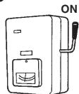
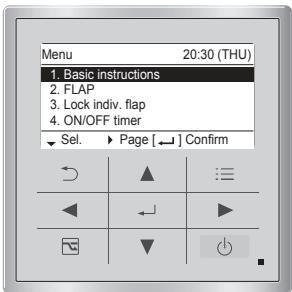
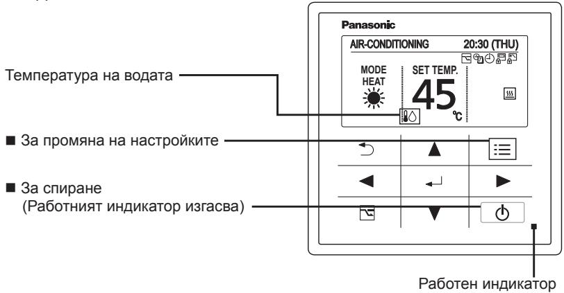
Names of Parts
INDOOR UNIT

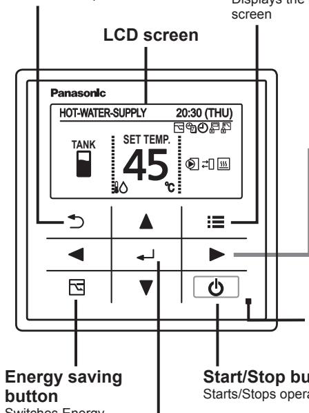
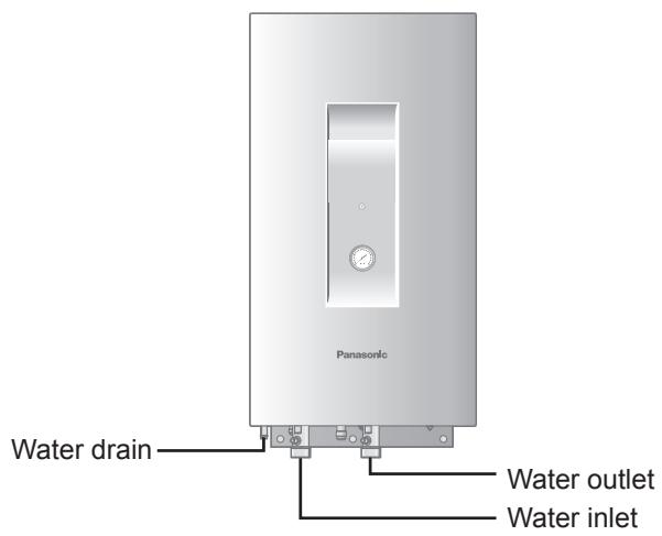
High-spec Wired Remote Controller (Optional: Model No. CZ-RTC5)
Return button
Returns to the previous screen.
Switches Energy saving/Normal operation.
Menu button
Displays the menu screen
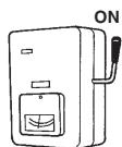
Operation indicator
Illuminates during operation. Blinks during alarm.
Start/Stop button
Starts/Stops operation.
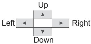
Cross key buttons
Selects an item.
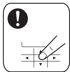
Note
Press centre

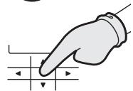
No glove

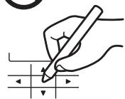
No pen
Menu screen
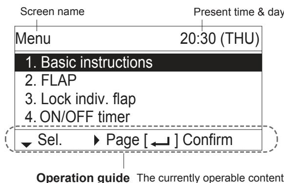
- ▲▼◁▶: Cross key buttons
:Enter button
Names of Parts
TANK mode
Setting information icons displayed on the top screen
| Icon | Description |
| Switching operation modes is prohibited. (Switching to Auto mode is also prohibited.) | |
| Remote control operation is restricted by a central control device. | |
| [ON/OFF timer] is set. | |
| [Weekly timer] is set. | |
| Energy saving operation is in process. |
| Icon | Description |
| Internal heater is active. | |
| Internal heater is abnormal. | |
| Internal heater is manually in process. | |
| OFF | Internal heater is not in process. |
| Control to prevent water freezing is active. | |
| External device ready demand*1 | |
| External device notice*2 | |
| External pump is active. | |
| Water is under sterilization. |
1 When the heat capacity for Air-to-Water is insufficient, output signal is sent to the external device.
2 When the notice is input from the external device, the icon appears on the wired remote controller.
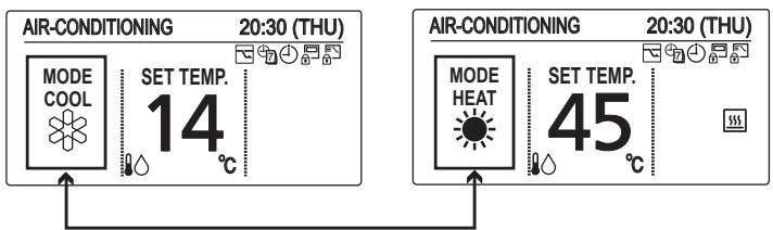
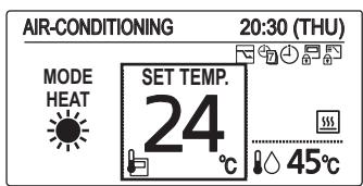
Air-Conditioning mode
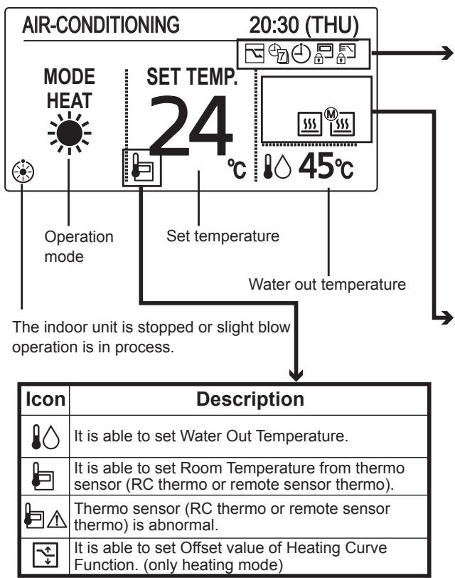
Setting information icons displayed on the top screen
| Icon | Description |
| Switching operation modes is prohibited. (Switching to Auto mode is also prohibited.) | |
| Remote control operation is restricted by a central control device. | |
| [ON/OFF timer] is set. | |
| [Weekly timer] is set. | |
| Energy saving operation is in process. |
| Icon | Description |
| Internal heater is active. | |
| Internal heater is abnormal. | |
| Internal heater is manually in process. | |
| OFF | Internal heater is not in process. |
| Control to prevent water freezing is active. | |
| External pump is active. |
When applying a power on for the first time, it is necessary to initialize the remote controller for Air-to-Water unit. Please refer to the installation instructions or consult the contractor.
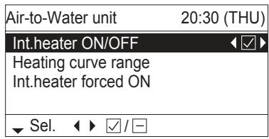
1 Display the menu screen.

To return to the previous screen
Press
To return to the top screen
Press 2 times.
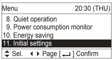
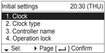
2 Select [Initial settings].
![PANASONIC S80MW1E5 - Select [Initial settings]. - 1](/content/2019/08/105597/images/c489418befcbc9a3514b465e3d53379b37b2b058bc6de4768b736157bc38d25d.jpg)
![PANASONIC S80MW1E5 - Select [Initial settings]. - 2](/content/2019/08/105597/images/21ed4d6351d3f3a8bebc79fffee2c64369902f9308b9f1587380bcde7d3b5ac4.jpg)
![PANASONIC S80MW1E5 - Select [Initial settings]. - 3](/content/2019/08/105597/images/8d5e873c3495a856593843449ea389aac55b1d1e6d9638a73301c33d8dc426dc.jpg)
![PANASONIC S80MW1E5 - Select [Initial settings]. - 4](/content/2019/08/105597/images/2f9c4918c271506a2b02841e0550f308cd576a1f27894b389855319043778a0d.jpg)
![PANASONIC S80MW1E5 - Select [Initial settings]. - 5](/content/2019/08/105597/images/719ba4f3534bd5df81ba13fe57961191ee65abce2c04bca6f23bdab26f0522b4.jpg)
![PANASONIC S80MW1E5 - Select [Initial settings]. - 6](/content/2019/08/105597/images/99c99dd2d76871f5625e288f69b0152323579d1c545e10b1227d86acae393600.jpg)
3 Select the item to set.


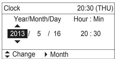
Clock
4 Set the date and time.


(Repeat)
(Press 2 times
to finish.)
-
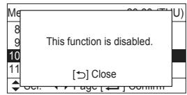
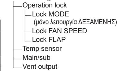
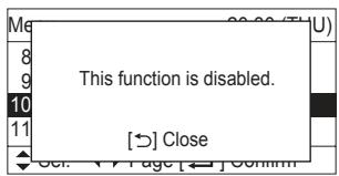
The Air-to-Water function is not applicable to the feature list No.2, No.3, No.6, No.7, No.10, No.11 and No.12 at the Menu screen (in TANK mode and Air-Conditioning mode).
-
FLAP
- Lock indiv.flap
- Filter info
- Outing function
- Energy saving
- Initial settings
12. Ventilation
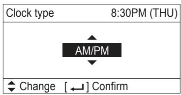
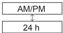
Clock type
4 Select the type to display.


(Press 2 times to finish.)
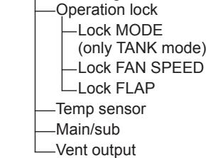
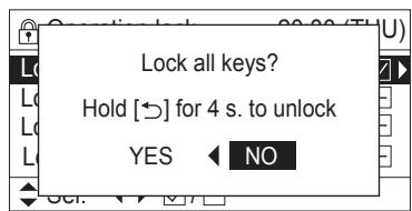
Operation lock
4 Select the type of lock and set to


(Press 2 times to finish.)
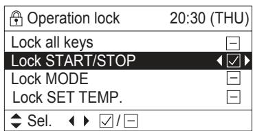
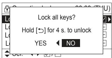
To cancel lock
Select [-] in step 4.
Only for [Lock all keys]
Select [YES].


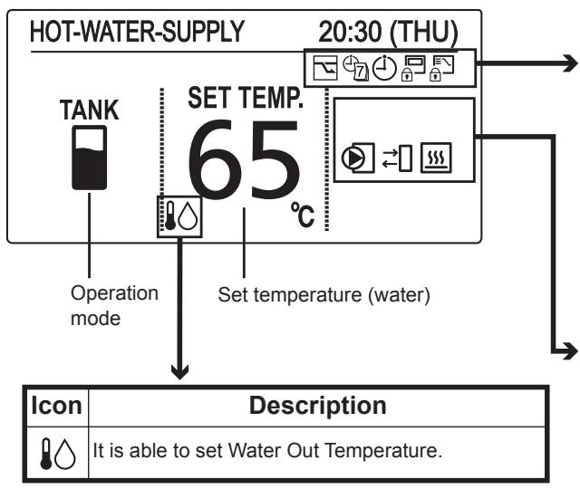
TANK mode
1 Start Operation

(The operation indicator illuminates.)
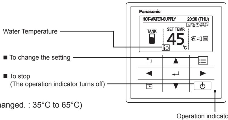
2 Change the temperature setting

(In TANK mode, only "SET TEMP." can be changed.: 35^ C to 65^ C )
(The cursor disappears.)
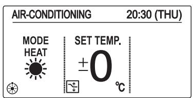
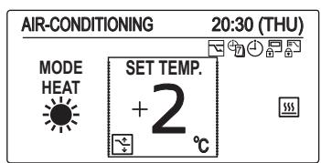
Air-Conditioning mode
[Heating Curve Function] (Only heating mode)
Supply water temperature is adjusted automatically, according to outdoor temperature.
Supply water temperature is able to adjust manually by changing offset value.
1 Start Operation

(The operation indicator illuminates.)
2 Change the setting
Under Heating Curve Control

To change the setting
To stop
(The operation indicator turns off)
Case: With use of Heating Curve Function.
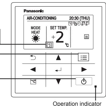
- Set temperature

(When the cursor is not visible.)
Heat (With use of Heating Curve): -5^ to +5^ (offset)

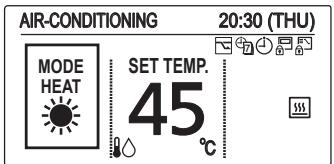
Case: With no use of Heating Curve Function.
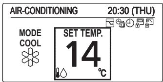
For cooling, see the note [Normal mode] below.
[Normal mode] With no use of Heating Curve Function.
Supply water temperature can be set.
1 Start Operation

(The operation indicator illuminates.)
2 Select the item to set

3 Change the setting

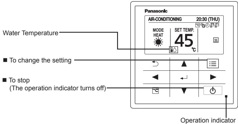
- Operation mode (e.g. Cool, Heat)
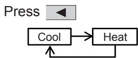
Set temperature
Press
(When the cursor is not visible.)
Water temperature
Cool: 5^ C to 20^ C
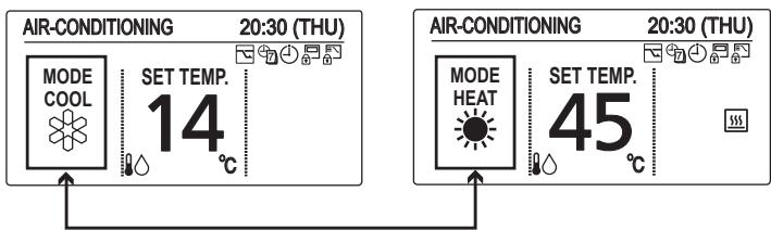
Heat (With no use of Heating Curve): 25^ C to 45^ C

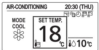
Room temperature (With use of remote controller thermo)
Cool: 18^ C to 30^ C
Heat: 16^ C to 30^ C


NOTE
- Group control function cannot be used for the Air-to-Water unit.
Be sure to confirm the individual remote controller connection is used for each Air-to-Water unit. - If your heating appliance is a radiator or floor heating, dew may be condensed on the appliance during defrosting operation.
In that case, turn on the Air-to-Water in heating mode to prevent condensation.
Operation Mechanism
Heating Performance
- Since this Air-to-Water utilizes outside air for heating, its heating performance deteriorates as outdoor temperature decreases. (Due to heat pump system) Information called "External device ready demand" is outputted from terminal of electrical component box.
Use another heating appliance using this information, etc.
- It will take some time until the supplied water temperature becomes warmer after heating operation started.
Defrosting
This appliance may start defrosting operation to melt frost form in the outdoor unit during long hour heating operation mode.
The indoor unit including Air-to-Water will stop for about 5 to 10 minutes at this time.
Heating Standby
The remote controller shows "Heating standby) on the display in the following mode and heating capacity will be limited.
- When operation started
- When Thermostat activated
- When defrosting
■ When Heating Operation Started (Only 3WAY VRF)
When changed to heating mode from stopped or cooling operation mode, the unit does not work for about 3 minutes for the sake of self-protection.
It may take about 5 to 10 minutes until the hot water is delivered after starting the heating operation.
Oil Recovery
The water pump may run at a slow speed in order to recover the oil in the system every 1 to 3 hours during cooling or heating operation.
The unit will automatically resume the original operation after about 5 to 10 minutes.
Remote Control Sensor
The temperature sensor in the Air-to-Water normally senses the water temperature and can also sense the ambient temperature of the remote controller. (room temperature) For the details, consult the shop you purchased.
Should the power failure occurs while the unit is running
When the unit automatically resumes operation after temporary power failure, it uses the same settings before the power was cut off.
Function of Air-to-Water Unit
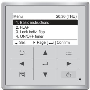
1 Display the menu screen.

TANK mode
3 Select the item to set.
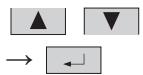
2 Select
[14. Air-to-Water unit].


Air-Conditioning mode
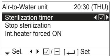
TANK mode
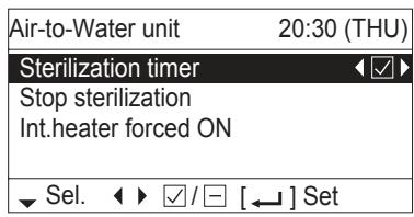
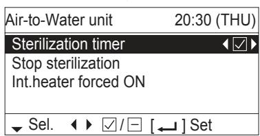
■ Sterilization timer
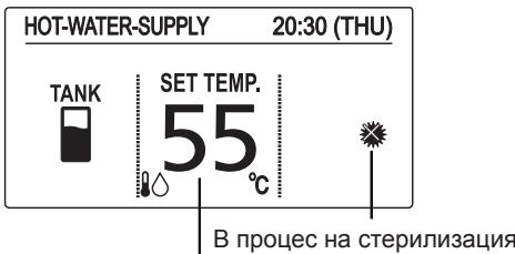
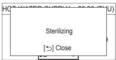
To prevent propagation of legionella bacterium in the tank, it is able to perform sterilization process once a week. While the sterilization process is performed, icon appears.
- Timer Setting
Under Sterilization process
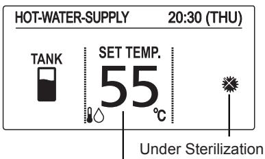
Target water out temperature for sterilization (If the set temperature is higher than temperature for sterilization, the set temperature is displayed.)
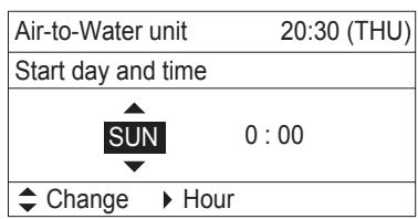
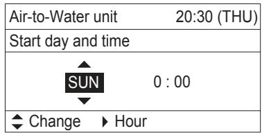
If "Sterilization timer" is enabled , the screen is switched to set the day of the week and time for sterilization process.
Set the day of the week and time for sterilization process.
Select the item by button and decide by button.
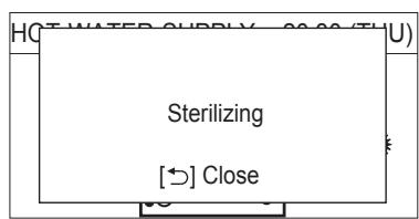
*Under sterilization, the set temperature cannot be changed.
- It takes a maximum of 4 hours to finish the sterilization process.
Caution: Be careful. Hot water may lead to a burn injury. - It is recommended to set the time not to overlap with other timer such as weekly timer.
- In the centralized controller, the set temperature of normal operation is displayed even during sterilization.
Although it is able to change the set temperature or turn ON/OFF by the centralized controller, sterilization process will continue.
If the Air-to-Water unit is stopped by the centralized controller during sterilization process, the Air-to-Water unit will be stopped after sterilization process.
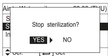
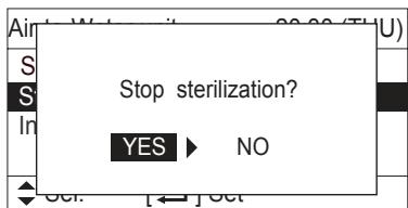
■ Stop sterilization
Under unavoidable circumstances, this function is enabled when the Air-to-Water unit must be stopped. The display on the right appears.
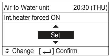
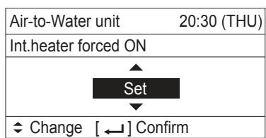
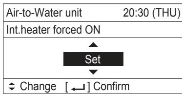
Int. heater forced ON
The internal heater of Air-to-Water unit can be turned ON manually. When the internal heater is turned ON manually, icon appears.
- This feature is for emergency operation when the outdoor unit has trouble. Contact to service technician definitely before setting this function.
- Password will be required before setting this function.
Press , button and select "Set" for forced ON.
Press 一 button after checking the confirmation screen.
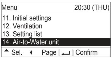
Air-Conditioning mode
Int. heater ON/OFF
The internal heater of Air-to-Water unit can be disabled. When the internal heater is disabled, icon appears. OFF
Press button to switch ON/OFF.
Heating curve range
It is able to select Heating curve range to automatically adjust the water out temperature with the outdoor temperature.
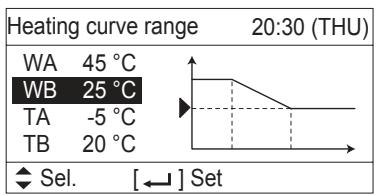
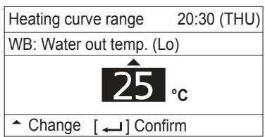
The initial setting is “±0” as the set temperature. Water out temperature can be changed (shift) from ‘-5’ to ‘+5’ as the set temperature.
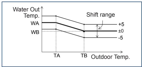
The Shape of Heating curve range is able to change at menu screen. Select the temperature to change by button. Press + button, it is able to change the selected temperature.
| Temperature range | |
| WA | 25~45°C |
| WB | 25~45°C |
| TA | -20~15°C |
| TB | 15~25°C |
The centralized controller displays the target water out temperature. It is only displayed information. It is not able to change the target water out temperature by the centralized controller.
Int. heater forced ON
The internal heater of Air-to-Water unit can be turned ON manually. When the internal heater is turned ON manually, icon appears.
- This feature is for emergency operation when the outdoor unit has trouble. Contact to service technician definitely before setting this function.
- Password will be required before setting this function.
Press , button and select "Set" for forced ON.
Press button after checking the confirmation screen.
Maintenance
Do not attempt to clean inside the unit by yourself.

WARNING
- For safety, be sure to turn the Air-to-Water off and disconnect the power before cleaning. (Otherwise, electric shock or injury may result because the fan is rotating at high speed.)
- Do not pour water on the indoor unit excluding water circuit. (This may damage the internal components and cause an electric shock hazard.)

CAUTION
- Never use solvents or harsh chemicals. Also, do not wipe plastic parts using very hot water. (This may cause deformation or change in colour.)
- Some metal edges and fins are sharp. Be careful when you clean those parts. (Injury may result.)
- Use a firm stool or ladder when cleaning an indoor unit installed in high locations.
Before Requesting Services
| Symptom | Cause | Action |
| The Air-to-Water unit does not operate although the power is turned on. | Power failure or after power failure | Press the power ON/OFF button on the remote controller. |
| The operation (power) button is turned off. | • If the breaker is turned off, turn the power on. • If the breaker has been tripped, consult your dealer without turning it on. | |
| Fuse blow out. | Contact your dealer. | |
| Poor cooling or heating performance | Water circuit of indoor unit is clogged with dust or obstacles. | Remove dust or obstruction. |
| Water temperature is very cold (heating). | Preheat the water over 25°C. (operate only Air-to-Water unit) | |
| The air intake or air outlet of outdoor units is clogged with dust. | Remove the dust. | |
| Improper temperature settings | See “Tips for Energy Saving”. (P.4) | |
| The room is exposed to direct sunlight in cooling mode. | ||
| Doors or windows are open. | ||
| Too many heat sources in cooling mode. | Use minimum heat sources and in a short time. | |
| Too many people in the room in cooling mode. | Lower the temperature setting. |
If your Air-to-Water unit does not work properly even after checking each item of “Before Requesting Services” and “Troubleshooting”
- Stop the operation immediately and turn the power off. Then contact your dealer and report the serial number and symptom. You also report if the inspection mark and the letters E, F, H, L, P in combination with numbers appear on the LCD of the remote controller.
- Never repair the Air-to-Water unit by yourself since it is very dangerous for you to do so.
Troubleshooting
Check before consulting or requesting services.
| Symptom | Cause / Action | |
| Noise | Sound like streaming water is heard during operation or after operation. | • Sound of water flowing inside unit • Sound of refrigerant liquid flowing inside unit • Sound of drainage water through drain pipe |
| Cracking noise is heard during operation or when operation stops. | Sound due to temperature changes of parts | |
| Dewdrops accumulate near bottom during cooling operation. | • Cold water accumulates dewdrop on the water piping. | |
| No operation (When the power is turned on immediately / When operation is stopped and resumed immediately) | • Operation is not activated for the first approx. 3 minutes because the compressor protection circuit is activated. | |
| Noise occurs during heating operation. | • Defrost operation is in process. | |
| Steam comes out during heating operation. | ||
| The fan continues to rotate even after the operation is stopped using the remote controller. | • This is for smooth operation. | |
■ Error code
| Code | How to Release | |
| E03 | Remote controller communication error | Automatic |
| E04 | Abnormal indoor/outdoor communication error | Automatic |
| F01 | Abnormal refrigerant sensor 1 (E1) | Automatic |
| F02 | Abnormal water outlet sensor 1 (E2) | Automatic |
| F03 | Abnormal refrigerant sensor 2 (E3) | Automatic |
| F10 | Abnormal water inlet sensor (TA) | Automatic |
| F11 | Abnormal water outlet sensor 2 (BL) | Automatic |
| L13 | Mismatched indoor unit | Reset (On and off of the power supply) |
| L16 | Test run for water circuit is not finished | Do test run for water circuit |
| L25 | Unmatched remote controller | Reset (On and off of the power supply) |
| P07 | Abnormal Internal heater overload | Cancel from the remote controller |
| P09 | Abnormal water flow | Re-run |
| P12 | Abnormal water pump speed | Re-run |
Chauff. int. force ON
Chauff. int. force ON

m = 311 ;
Selecteer [YES (Ja)].


TANK-stand
Heat (Verwarmen)(Met Heating Curve
(Verwarmingscurve)): -5^ t/m +5^ (offset)
Heat (Verwarmen)(Zonder Heating Curve
(Verwarmingscurve): 25^ C t / m 45^ C
- FLAP
- Lock indiv. flap
- ON/OFF timer
Sel.
Page
] Confirm
O8nyoc 8eitoupyia To npov 8eioupyiko Tepiexóveo EmuaviéTai aIawc stnv oHovn.
- FLAP
- Lock indiv. flap
- Filter info
- Outing function
- Energy saving
- Initial settings
12. Ventilation
Poλói
Hnkora He n3noJ3BaIte n He cBxpaHЯBaIte 6eH3nH nIpyr3aIaJIteJIHn I3npaEHH nI TeHuOCTN B 6JIu3oCT Do MoyIb3dIyx-BOJa - ToBa e MHOro OnaCHO.
He n3no3BaIte TOnI ypeI B nOTeHuaJIHO eKcIIIO3INBHa aTMocpepa.
Hnkora He doKocBaIte ypea c Mokpn pBue.
He nbxaIte npbCTn nIIN dpyIn
npedMeTn BbB BbHsHnI NII
BbTpEshNMaOdyIHaMoDyJa
Bb3dYx-BoJa, BbPTaIuTe ce qactn Morat
da npuHnT HapaHyaHnI.

Ako xIaIINHnIaREHT BNe3e B KOHTaKT C OTKpIIT PIIaMbK E Bb3MOxHO da Ce OTdJIIN TOKcUHeH ra3.
OT rIeHa TOnka Ha 6e3OpacHocCTTa, HeIpeMeHnO n3KlIoUeTe MoDyJa Bb3dYx-BoDa n OTKaueTe 3axpaHbaHeTo npEi NouchTBAHe NII NOcnyKBaHe.
N3dbpnaTe 7eCena OTKaTa, N3KJIbOte IpeKbCBaHa NIN N3KJIbOte 3axpaHbAHeTo, 3a Da N3OJnPaTe Moyla Bb3dyx-BoJa O rIaBHOte eJeKTpo3axpaHbAbe H Cny Ha N3BbHpeHa CNTyaUa.


He octabraye notpebnteIte da NOuchCTBaT BbTpewHOCTTa Ha BbTpewHnry N BbHNHnMy Moyn. AnraxnpaJTe OTOpN3npaH dINbP INN CneuJaNCT NO NOuchCTBaHTo.
B clyaHa Heu3npaBnOCT Ha To3n ypei, He ro pemOnTnpaIte cam. CbpxeTe ce C dInIbp No npoJaX6bIte nIi cepBn3eH ueHTbp 3a peMOHT.

OcnrgypeTe po3eTka, kOaTo da 6bde
PON3BaHa N3KJIIOUHTeJIHO CAMO
3a BCEKn MOdYn, a PpeKbCBauch 3a
eNeKTPo3axpaHbAHeTO, PpeKbCBauch pRn
yTeUka Ha 3a3EmraBHeTO (ELCB) nIi
yCTPOINCTBO 3a OCTaTBueH TOK 3a 3aUNTa
pRn PpeTOBapBAHe TpRA6Ba Da 6bDaT
OCNrypeHN B eDHa JInHn.
OcnrypeTe n3XoJHO 3axpaHbaHe
n3KJIIOUHTeJIHO cAmO 3a BCEKN MOyJ, a
IbJIHO IpeKbCBAHe OT eJeKTPuYeCKaTa
MpeJa C KOHTaKTHN peJIeTa BbB BCNUKIn
IOnIOcN TpA6Ba Da ObJe BKJIIOUeHO
BbB OIKCupaHOTO OKa6eJIraBaHe BCbOTBeTCTBnE C npabNuIata.
3a npedotbpaTBAHe Ha
ONaCHOCTN OT NOBpeHa Ha
H3OJaTAt, MoyIbT Tp8Ba Da
6bJe 3a3eMeH.


He n3noJ3BaIte MoInΦuIpaH Ka6eI, HacTaBeH Ka6eI, yDbJxNtTeI INn HeyToUHeH Ka6eI Ce npdeoTbpatn ppeprBaHe n Ioc


Cnpete n3noI3BaHeto Ha npOyKta, KOrato Ce IoBn HraKaKba aHOMaIIa/ NOBpeDa N3KJIIOUte UeNcEla OT KOHTaKTA NII N3KJIIOUte 3axpaHBAHeto N PpeKbCBaaya.
(ОпасноТ OДИМ/Огьн/ТOKOB yдар)
Приимери на anHomajnia/поврда:
-ELCBn3knIouBaYeCTO.
- Пюдуктпонякога He 3anoyba pa6oTa npi BkJIIOUBAHe.
3axpaHbaHeTo NOHkOra IpeKbcBa npn IpemecTbHe Ha KaBeNa.
- По врeme на paBOTa Има МИрИЗма на ИЗгоряно Или Heo6nuaeH IyM.
-Моульт eдформпан Ипн Heобчайно ropeц.
- OТ bьтpeшнma мodyл теу boda.
3axpaHbauT Ka6eN nn 7eNcTe HeoBuHaHO ropeu.
-Скорочта на вентлиатoga He може за ce KOHTPOЛIPA.
-Модуньт сира за работи Ведна дори akо e BKлочен 3a работа.
- BeHTnIaTOpbT He cnpa dOpn aKo pa60TaTa e cnpraHa.
Cbpxte ce He3a6abHc MeCTHnA DnIbP 3a PndpbXka/peMOHT.

BHIMAHNE

To3n ypeTe npedHa3NaueH da 6bJe n3NoJ3BaH OT ekCnept nnn ObuyeHn IOTpeBnteN B MaRa3nHn, B Jekata npOMuJleHOCT N BB BfepmN, nnn 3a TbproBcKa ynotpe6a OT HeInpocecnoHaJIHn liua.
To3n ypeJ moKeJa ce n3PON3Ba OT Deca Ha Bb3pact 8 n IOBeue rOdInn oT Xopa C ORpaHnueHnФn3NueCKn, CETNBn NJIyMCTBHeHn CNOCo6HOCTn NJI NINCA Ha ONIT N PO3HaHnA, aKO Ce Na6JIIODaBAt NJI Ca INHCTpyKTIpaHn OTHOCHO N3PON3BaHETo Ha ypeDa nO be3OpacEn HauHn, n OcB3HaBaT ONaCHOCTIte, KOINT TOBA BKJIIOUBy.
He 3aIenBaIte HnIcO Ha n3XoJa 3a Bb3dUx Ha BbHsHnA MoyI. ToBa e ONaCHO, Tb' KATO BEHTnlaTOpbT Ce BbPTN C BnCoka CKOpocT.
He dokocbaTe cmykaTeIaNIOCTpTe aJyMnHneBn pe6pa Ha BbHsHnT MoDyI. MoKe da ce HapAHnte.
He cyaIte n He cTbIbaiTe Bbpxy ypeDa. MoKe cIyuAaHOn da paIaNHeTe.
He noctabraye HnkaBn npedmetn Bbypxy KOxyXHA BEHTIATOPA. Moxe da 6bndeHapaheH nn MOynbT da 6bnde NOBpeDe


bblITAPCKN
BENEXKA
KoMnpeocobT moKe noHrkora da cnpe no BpeMe ha rpbMOTeBvUHb6ypn.ToBa He e MexaHnuHa NOBpeJa. MoyIbT aBTOMaTHUHO Ce Bb3CTaHOBRA CneD HkOKIo MmHyTN.
- AHRINCKNRT e3NK e3NKbT Ha opnHnHaHnHTe INHCTpyKuIN.ДуNTe e3uCi ca npBeOD OT opnHnHaHnHTe INHCTpyKuIN.
Baxha nHOpMaZna 3a n3nOJ3BaHnXlaDInJeH aReHT
To3n npOdykT cbIbPkaФnyOpupaHn napHnKOBn ra3OBe, KOINTCa BKNIOUeHN B IpoTOKOJa OT KnOTO. He n3XBpIraTe ra3OBe B aTMocpepata.
Bud Ha xlaadinHnra areHT: R410A
GWP(1) CTOHOCCT: 1975
(1)GWP = NOTEHUan 3a rIIObAHO 3aTOIIHHe
Bb3MOxH O da ce n3nCKBa nepnoDnHa npOBepka 3a n3TnuaHe Ha xnaDInJe aneHT cbrJaCHo eBpOneIKcOTOn mecTHo 3aKoHOdaTeIcTBO. 3a nobYe nHΦopMaunCe o6bpHeTe KbM Baunn dInIbP.
Мерки等相关 y沌otpe6a
Инсталаре
To3n Moyn Bb3nyx-BoJa Tpr6Ba Da ce nHCTaInpa npabNIO OT KBaINΦuIcpaHn TexHciu B CbOTBeTcBne C INHCTpyKUnTe 3a INCTaInpAHe, PpeOCTabeHn C Moynla.
IpeiHnCTaIInpaHe npOBepeTe daIIN HAnpexKeHneTo Ha eIekTpncEckOTO 3axpaHbAbe BbB Baunr DOM nIIN oΦnc e CbIoTO KaT0 HApexKeHneTo, IOKa3aHO Ha Ta6enKaTa.

ПРЕДУПЕЖДЕНЕ
I36yRbAte CJeDHnte MeCTa 3a IHCTaJInpaHe.
MecTa, B KOnTo IMa HaNuYHe Ha TropIMn rA3OBe N dIiM. CbIo TaKa, MecTa C OcOBeHO BucOKn TempePaTyPi, KaTO napHnU.
MecTa, KbIeTo ca nOCTaBeHn IpeKaJIeHO BVCOKN OBeKTH, reHepuapuTOnPiHa.
BHHMaHHe:
I36raBte HnctaHpaHeTo Ha BbHnHnMoynHa MeCTa, KbTeO CoNeHa MOpcka BOa MoKe Da npbCKa DnpeKTHo Bbpxy Hero nPi nHaNnue Ha cepHNCT Bb3dYx B 6n30cT Do cna. (3a da 3aunntte MoDyNa Bb3dYx-BOda OTexkKa Kopo3nA
Kabéni
BcnuKn Bp3kn Tp6Ba Da otroBapr Ha MeCTHnTe eNeKTpoTeXnueckn HOpMaTnBn. (KohcyTnpaIte ce c Baunu DnIb np IIn KBaIuΦnupaH eNeKTpoTeXnK 3a NopDnObHocTn.)
BceknMoynTp86Ba da 6bJe npabunH0 3a3emeh csc 3a3emntenH npoBOHNK nJn Ype3 eJektpnuecknte KaBeJI.
- OkabéJЯBaHeTo TpáBbA da ce N3BbPbBA OT KBaJIInΦnIupaH eIeKTpOExHnK.
Побrotовka 3a paбota
BkJIouYe 3axpaHbAHeTo 5 yaca npeNi HaayanoTo Ha pa6oTaT.
(3a noɪdprəBaHe)
OCTaBeTe 3axpaHbAHeTo BKJIIOueHo 3a HENpeKbChata yNtpe6a.
3ABEJIEXKA
I3dbpnaTe ⅢeCenaOT rHe3dTo, n3KIOUcTe npKeBcBaaynINn3KIOUcTe 3axpaHbAHeto, 3a Da n3OJIpaTe MoyJaBb3dyx-BoA oT rIaNbHOTO eJekTpO3axpaHbAhe, aKO Hma daCe n3PON3Ba pOdoBnKInTeJHO BpeMe.
CbBETn 3a neCTeHe Ha eHeprna
N36yBaIeTe
He 3anyuBaIte Bb3dyuHnT CmyKaTeI n I3xOda, IINBxOda n I3XOda 3a BOda Ha MoDyJa. (Ako HyaKo OT T8x e 3anyuHen, ypeDbT Hma da pa6OTn Do6pe n MoKe Da ce NobpeDi.)
По Врeme Ha oxлалдаме Изполтваite ceHHиц, сорилл 3aBeCn, 3a Да ce пpeДOTВраТи habЛиЗАнTo Ha npяka CJlbHYeBa CBeTJIInHa B CtaЯТa.
HanpaBete cIeDHOTo
BnHaHn noDlbPkaIte BODaTa YnCTa. (IInncata Na BOIOPOdaBaHe ige BNoSh pa6oTa n ige nobpeDuMoynpa.) "PoDpBxKka" (P.108)
3aДапгелOTbpaTnTeИЗБжДанeHaOBpa6ToHЯOT KJIIMMaTnKa Bb3dYx,ДрьЖTe Пpo3OpuTe,BpaTnTe IN BCNUKINpyrN OTBOPn 3aTBPOpeHn.
YcIobnHa pa6ota
I3noJI3BaIte To3n MoIyI Bb3Iyx-Boa B cIeIHHa TeMnepeAtpeH dIana3OH.
- FLAP
- Lock indiv. flap
- Filter info
- Outing function
- Energy saving
- Initial settings
(CBetBa pa6OThnI INHdNkAtOp.)
(Korato KypcopbT He ce BnKda.)
Heat (OToPnIeHne) (C n3noJI3BaHe Ha KpIbHa 3aqrpaBaHe) : -5°C Do +5°C (Kopekun)
3a oxnaekdahe, BuxTe 6eJekkaTa [HopmaJeH peKm] NO-dony.
[HopMaIeH pexm] Be3 n3noJ3BaHe Ha cyHKuTЯ KpNbHa 3aIrpBaHe.
Mоже да ce 3адe Temпература Na пода вана Тбд.
1 CtapTupaHe Ha onepaun
HaTnucHeTe
(CBetBa pa6OThnI INHdNkAtOp.)
■Пимер:БezиинлзВаHe Na КрИЗЯНЗагрЯВaHe.
2 36epete eIeMeHT 3a HacTpoiBaHe
HaTnchete
HaTnchete (Korato KypcOpbT He ce BnXda.)
Tempepatya Ha BodaTa Cool (OxnaKdaHe): 5^ do 20^
Heat (Отоленье) (Бezиизолбан Ha Крва Ha 3аграва): 25^ до 45^
CtainHa TemnepaTpya (c n3noJ3BaHe Ha TepMo DInCTaHcNoHHo ynpabJIeHne)
Cool (OxnaKdaHe): 18^ do 30^
Heat (OtoPHeHne) : 16^ do 30^

3A6EJIEXKA
He moKe Ia ce n3no3IbA cyHKznaTa 3a rpyNoB KOHTpoJ 3a MoyJa Bb3dyx-BoJa.
Ybepete Ce, Ye cTe nOTBbpDnIIN 3N0n3BaHeTo Ha Bp3KaTa C INDNIBNuAJIHOTO DnCTaHcIOHO ynpabNeHne 3a BCEKNMOyN Bb3dyx-BOda.
- Ako OTOnnIteHnIe TBypeI e paINaTOp, IJIIN POnOBO OTOnJIeHne, Bb3MOxHO e o6pa3yBaHeTo Ha KOHN3 npi peKIM Ha pa3Mpa3raBaHe.
BTo3n cnyaBKnUoyTe Moyn Bb3dyx-BoDa B pexim Ha 3arpaBaHe, 3a Da npedeTbpaTne o6pa3yBaHe Ha KOHdeH3.
MexaHn3bM ha pa6oTa
■ПОНЗВОДИТЕЛНСТΗ OТОПЛЕНИС
TbKATO MOyIbTBb3dyx-BOa n3n03nBa BbHWeH Bb3dyx 3a OTONJIeHne, pa6oTaMy npu peKIM Ha OTONJIeHne CE BNOIaBpN pONIKaBaHe HA BbHNHTe TEMNEpaTyPi. (Iopadn CnCTemata Ha NOMATA 3a 3arpaBaHe) IOnaBa ce INΦOpMaunra ,BbHsHo yCTPOIcTBO rTOBO pRn HEOBXODIMoCT"OT TepMNHaNa HbONoka C eNEkTpuYeCKN KOMNoHETN. N3noJ3BaIte Dpyr OTONJIteJeH ypeD, KaTO n3noJ3BaTe Ta3n INΦOpMaunr nT.H.
HyXHO e 3BecTHO BpeMe IOKaTO TemnepaTypaHa HnoDaBaHaTa BOda CE NOBUN CneJ KaTO e CTapTnpaH peKIM Ha OTONJIeHne.
Pa3Mpa3BaHe
To3n ypeJ moKe da 3anoHpe pa3mpa3raBaHe, 3a da pa3mpa3n cKpeKa, o6pa3yBaJI ce BbB BbHNHnMoyn, npn npOdbLnKntenHa pa6Ota B pexm Ha OTonJIeHne. BbTpeuHnT MoUyBb3dyx-BoJa ue cnpe 3a OKoI0 5 Do 10 MNHT B To3n MOMeHT.
B roTOBHOCT3a peXIM OToPJIeHne
Диctанционното noka3Ba,“(TOTOBHOC3a OTONJIeHne) HaДиСпляКATO KanaцNTeTbT Ha OTONJIeHne Ie 6bde Oрразниуен.
Korato cTapuTpa paBota
Korato e akTbBpah TepMoCTaT
- Пуразмразуbaнe
Korato e cTapTnpaH peXIM OToPJIeHne (Camo 3WAY VRF)
Korato ce npeBknouv B pekim Ha 3aqrpaBe OTe CnpraHo
PONOxKeHne IJN OT pekim Ha OXJaXDaHe, MOyIbT
He pa60Tu 3a OKoTo 3 MNHyTu, Nopadn aKTNBpuHa
camo3aunTa.
MoKe Da OTHeMe 5 Do 10 MNHyTu DOKaTO TOnla BOda 6bJe
NoJaDeHa CneD CTapTnpaHe Ha pekim OTOnJIeHne.
Perehepuhe Ha maclo
Bodnata nomna moke da paobTu Ha Hncka ckopoc, 3a da pereheepnpa macnoTo B cncTeMaTa Ha BCEKn 1 do 3 yaca no BpeMe Ha oxIaxkDaHe nII IN OTONJIeHne. MoyltbT abTomatuHo Iue Bb3ctaHOBN PbPBOHaayHnra peKm Ha paobTa cneI Okono 5 do 10 MNHyTN.
Ceh3op Ha dinCTaHcNoHHOTy ynpaBJeHne
TempepynIaTmKHaMoynaBb3dyx-Boa oBnKHOBeHOOTyHTaTeMpepypTaHaBOdaTn MOKe CbIoo DaOTYeTo OKoHnHaTaTeMpepypaHa DnCTaHOnHOToYnpaBHeHne.(CTaHaTeMpepypa) 3aNoPob6HoCTN,KOHcyPTnPaiTe CeMaRa3nHa,OT KOITTO CTe HApabuIN NOKyPkata.
Ako 3axpaHbaHeTo cnpe,doKaTo MoyIbT pa60Tu
Korato MoDyIbT aBtOMaTnUHNo IOdHOBn pa6Ota cIeI BpemHe IpeKbCBAHe Ha 3axpaHbAHeTo, ToI n3PON3Ba CbIHTe HAcTpOiKn IpeDi CNIPAHeTo Ha 3axpaHbAHeTo.
- Hac tropon Ka TaMepa
Ako „Sterilization timer (Taimep 3a cTeprnna"e aKtBnpaH ,ekpaHbT ce aKTNbnpa 3a da ce 3aadaJeH OT CeMncaTa N ac 3a N3BbpWbaHe Ha cTeprnna.
3aainTe den OT ceMncaTaNac 3a ctepniln3aun.
I36epeTe enemEnT Upe3 6yToH n onpeJeTe Upe3 6yToH.
B pOuec Ha cTepeJIn3aun
TemnepaypataHa BODaTa Ha n3xoJa 3a cTeprnIn3aun (Ako 3aJaDeHata TemnepaTpe NO-BvCoka OT Ta3n 3a CTeprnIn3aun, ce IN3BExKa 3aJaDeHata TemnepaTypa.)
- Пи сөрөлүзаця, төмөратура т He може дa ce поменя.
* OThema maksymm 4 yaca 3a 3aBbPwBaHe Ha npouceHa CTepnJIn3aIyra.
BHMaHHe: BbTeB HmMaTeJIHn. Topeuata BOa MoKe da DOBeJe Do n3rapaHnJ.
* PnpopbUba ce da 3aadaTe BpeMe, KOeTo He ce npnOKpNbBa C dpuyn 3aadaHn HacTroKn Ha TaMepn, KaTO CeDMNUHn TaMep.
*B ueHTpaHnna KOHTpOneP, 3aJaDeHaT a TempePaTypa 3a HopMaJIHa pa6oTa ce N3BeJda dopn npri cTeprnIIn3aUria.
BbnpkeK, ye moKe da ce npomeHn 3aadaeHaTa TempeaTpya, nIi da ce n3BbPm BKJ./ I3KJ. Ot cEHtpaHn KoHTpOneP, pOuecBT Ha cTePNn3auny ige npoDbKn.
Ako moynbT B3dyx-Boa e cnprn OH TcHtpaHn KOnTpOJIep nO BpeHa cTePun3aUria, ToToIe CnpE CteK KaTO 3aBbPsI pOueca Ha cTePun3aUria.
■ Stop sterilization (Спунане на сөрллзүй)
При Низбеки Иобсторелста, таи Функця може за се akтувра, korato мodyлт Вьздух-вoda трава на сп reasonably. Поваясе ekраньт, поочен вяяно.
Int. heater forced ON (Пьв. HarpeBaTeJ npHnydnteHb BKJI.) Пьвчнят harpeBaTeJ ha moyn Bb3dyx-BoJa moRat da 6bDat BKJI. pbHy Korato BbTpeshnT HarpeBaTeJ b BKJI. pbuHO, ce noBraHa IkoHa.
* Ta3n cyHKcna e 3a abapnHa pa6ota, KOrato BbHsHnT Moyn e NobpeDeH. CbByxete ce cbc cepBn3eH TexnK npdeI da 3aadTe Ta3n cyHKcna.
* N3nckBa Ce npoJa npeDn Da ce 3aDaTe TaNn FyHKuJy.
HaTnSchTe A, 6yToH nI36epeTe „Set (3aJa)“ 3a npInHydnteHNo BKJI. HaTnSchTe 6yToH cIeД kaTo npOBepiTe ekpaHa 3a NOTbpyKdEHeNe.
PexnKJImMaTn3aun
Int. heater ON/OFF (Вът. HarpebaTeJ BKЛ./ИЗКЛ)
BbtpeunHnT HarpBeaTeHa Moyn Bb3dyx-Boa MoKe Ja 6bJe DeakTbInpaH. Korato BbtpeunHnT HarpBeaTeHa deakTbInpaH, SS ce noyBa IKOHa. OFF
HaTnCHeTe 6yToH 3a da npEeKnIOUHTe BKN./I3KJI.
He n3nBaIte BOa BbB BbTpEWHnA MOyI DOKaTO He n3KlnOHTe BOHNIA KpIg.
(Toba ue NOBpeDN BbTpeSHHnTe KOMNoHEHTn U ue npEdu3Bnka onaCHOCT OeJekTpnuyeckn ydap.)
BHIMAHNE
Hnkora He n3noJ3BaIte pa3TBOpNTeIN nn pa3aJaun Xmukan. He nouchTe pJactMacobTe qactn c Mhoro ropeua Boda.
Int. heater forced ON (Dhl. isitici zorla AÇİK)
Int. heater forced ON (Dhl. isitici zorla AÇİK)
Indoor unit
Air-to-Water Heatpump (Type W1)
| Model Name | S-80MW1E5 | S-125MW1E5 | |
| Power Source | 220 / 230 / 240 V ~ 50Hz | ||
| Cooling capacity | kW | 8.0 | 12.5 |
| BTU/h | 27,300 | 42,700 | |
| Heating capacity | kW | 9.0 | 14.0 |
| BTU/h | 30,700 | 47,800 | |
| Sound Pressure level | dB(A) | 37 | 39 |
| Sound Power level | dB(A) | 50 | 52 |
| Unit Dimensions (H×W×D) | mm | 892×502×353 | 892×502×353 |
| Net weight | kg | 43 | 43 |
Corresponding language table
| English | François | Espanol | Deutsch |
| Air-to-Water Heatpump (Type W1) | Pompe à chaleur hydraulique (Type W1) | Bomba de calor de unidad de aire-agua ( tipo W1) | Luft-Wasser-Wärmpumpe (Typ W1) |
| 3WAY (Type MF2) | 3WAY (Type MF2) | 3WAY ( tipo MF2) | 3WAY (Typ MF2) |
| English | Italiano | Nederlands | Português |
| Air-to-Water Heatpump (Type W1) | Pompa di calore aria-acqua (tipo W1) | Lucht-noar-Water Warmtepomp (type W1) | Bomba de Calor Ar-Água (Tipo W1) |
| 3WAY (Type MF2) | 3WAY (tipo MF2) | 3WAY (type MF2) | 3WAY (Tipo MF2) |
| English | Еλληνικη | Български | Türkçe |
| Air-to-Water Heatpump (Type W1) | Θερμική αντλία κλιμαιτιστικό (Τύπος W1) | Терmonомпа Въздух-вoda (тун W1) | Havadan Suya lsi Pompasi (W1 tipi) |
| 3WAY (Type MF2) | 3WAY (Τύπος MF2) | 3WAY (тун MF2) | 3WAY (MF2 tipi) |
Corresponding language table
| English | François | Espanol | Deutsch |
| Model Name | Nom du modèle | Nombre del modelo | Modellbezeichnung |
| Power Source | Source d'alimentation | Fuente de alimentación | Spannungsquelle |
| Cooling Capacity | Capacité de refroidissement | Capacidad de refrigeración | Kühlleistung |
| Heating Capacity | Capacité de chauffage | Capacidad de calefacción | Heizleistung |
| Sound Pressure Level | Niveau de pression sonore | Nivel de presión acústica | Schalldruckpegel |
| Sound Power Level | Niveau de puissance sonore | Nivel de potencia acústica | Schalleistungspegel |
| Unit Dimensions (HxWxD; mm) | Dimensions d'unité (HxLxP ; mm) | Dimensiones de la unidad (Alto x Largo x Ancho; mm) | Geräteabmessungen (H x B x T [mm]) |
| Net Weight (kg) | Poids net (kg) | Peso neto (kg) | Nettogewicht (kg) |
© Panasonic Corporation 2015
Printed in Malaysia
Authorised representative in EU
Panasonic Testing Centre
Panasonic Marketing Europe GmbH
Winsberging 15, 22525 Hamburg, Germany