
100 IC 6-ST - Loudspeaker FOCAL - Free user manual and instructions
Find the device manual for free 100 IC 6-ST FOCAL in PDF.

| Product type | In-ceiling speaker |
| Brand | Focal |
| Model | 100 IC 6-ST |
| Category | Speaker |
| Nominal diameter | 245 mm |
| Depth | 120 mm |
| Weight | 1.5 kg |
| RMS power handling | 80 W |
| Maximum power | 160 W |
| Impedance | 8 ohms |
| Sensitivity | 89 dB (2.83 V/1 m) |
| Frequency response | 55 Hz - 25 kHz |
| Woofer | 6.5-inch (165 mm) glass fiber |
| Tweeter | 1-inch (25 mm) inverted dome tweeter |
| Cutout diameter | 200 mm |
| Color | White (paintable) |
| Maintenance and cleaning | Clean with a dry, soft cloth. Do not use abrasive products. |
| Safety | Professional installation recommended. Follow local electrical codes. |
| Spare parts and repairability | Contact Focal after-sales service for spare parts. |
| General information | In-ceiling speaker designed for high-quality sound reproduction. |
Frequently Asked Questions - 100 IC 6-ST FOCAL
User questions about 100 IC 6-ST FOCAL
0 question about this device. Answer the ones you know or ask your own.
Ask a new question about this device
Download the instructions for your Loudspeaker in PDF format for free! Find your manual 100 IC 6-ST - FOCAL and take your electronic device back in hand. On this page are published all the documents necessary for the use of your device. 100 IC 6-ST by FOCAL.
USER MANUAL 100 IC 6-ST FOCAL
natural_image
Circular mechanical component diagram with concentric rings and mounting holes (no text or symbols)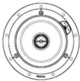
natural_image
Circular mechanical component diagram with concentric rings and mounting holes (no text or symbols)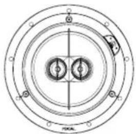
natural_image
Pure technical diagram of concentric circular components with no text or symbols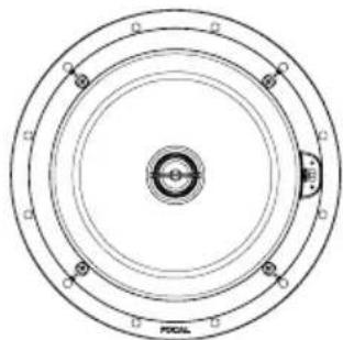
natural_image
Circular mechanical component diagram with concentric rings and central hub (no text or symbols)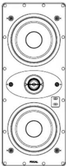
natural_image
Technical diagram of a dual-tiered speaker or audio device with mounting holes and central button (no text or symbols)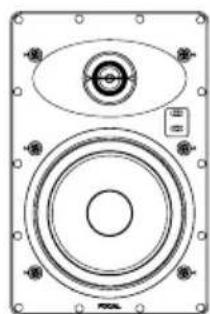
natural_image
Technical line drawing of a speaker or amplifier with concentric circles and mounting holes (no text or symbols)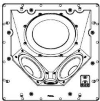
natural_image
Technical line drawing of a mechanical component with mounting holes and central circular features (no text or symbols)Français : page 11
English : page 16
Deutsch : seite 21
Italiano : pagina 26
Español : página 31
natural_image
Top-down perspective view of a room layout with a sofa, three chairs, and a central wall (no text or symbols)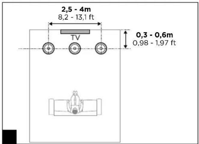
100 SERIES
natural_image
Technical line drawing of a speaker with two inset views showing front and side views (no text or symbols)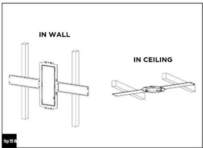
100 SERIES
natural_image
Technical line drawings of a speaker with multiple circular components, shown from top to bottom views (no text or symbols)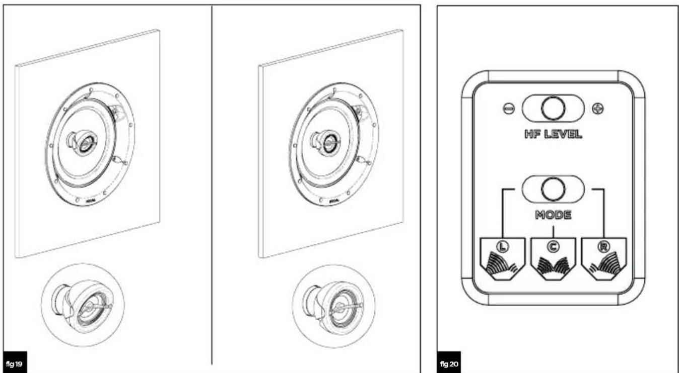
100 SERIES
| 100 ICW 5 100 ICW 6 100 IC 6ST | |||
| Type | In-wall/In-celling2-way coaxial | In-wall/In-celling2-way coaxial | In-celling stereo2-way coaxial |
| Drivers | 5" (13cm) Polyglass Midbass.1" (25mm) Al inverted dome Tweeter | 6 1/2 " (16.5cm) Polyglass Midbass.1" (25mm) Al inverted dome Tweeter | 6 1/2 " (16.5cm) Dual voice coil Polyglass Midbass.1" (25mm) Al inverted dome Tweeter |
| Sensitivity (2.83V/1m) | 88dB 89dB 89dB | ||
| Frequency response (+/-3dB) | 65Hz-23kHz 62Hz-23kHz 60Hz-23kHz | ||
| Low frequency point (-6dB) | 56Hz 50Hz 48Hz | ||
| Nominal impedance | 8Ω 8Ω 2x8Ω | ||
| Minimal impedance | 7.3Ω 7.3Ω 2x6.7Ω | ||
| Recommended amplifier power | 15-100W 25-100W 25-100W | ||
| External dimensions (∅/Depth) | 7 1/4 "×3 2/6.4 " (184x87mm) | 8 3/6 "×3 4/6.4 " (208x95mm) | 8 3/16 "×3 4/6.4 " (208x95mm) |
| Cut-Out diameter | 6 19/6.4 " (160mm) | 7 1/4 " (184mm) | 7 1/4 " (184mm) |
| Depth from wall | 3 15/6.4 " (82mm) | 3 37/6.4 " (91mm) | 3 37/6.4 " (91mm) |
| Net weight (with front grille) | 3.19lbs (1.45kg) | 3.3lbs (1.50kg) | 3.86lbs (1.75kg) |
| Packing dimensions (WxDxH) | 9 5/8 "×9 5/8 "×6 5/16 " (245x245x16mm) | 10 5/8 "×10 5/9 "×6 1/16 " (270x270x170mm) | 10 5/8 "×10 5/9 "×6 1/16 " (270x270x170mm) |
| Total weight (with packaging) | 4.52lbs (2.05kg) | 4.96lbs (2.25kg) | 5.29lbs (2.40kg) |
| 100 ICW 8 100 ICLCR 5 | |||
| Type | In-wall/In-celling2-way coaxial | In-ceiling2-way | |
| Drivers | 8" (2cm) Polyglass Midbass.1" (25mm) Al inverted dome Tweeter | 2 x 5" (13cm) Polyglass woofers1" (25mm) Al inverted dome tweeter8" (2cm)Polyglass passive radiator | |
| Sensitivity (2.83V/1m) | 90dB 92dB | ||
| Frequency response (+/-3dB) | 53Hz-23kHz 65Hz - 23kHz | ||
| Low frequency point (-6dB) | 40Hz 55Hz | ||
| Nominal impedance | 8Ω 8Ω | ||
| Minimal impedance | 6.9Ω 4.6Ω | ||
| Recommended amplifier power | 25-150W | 25-120W | |
| External dimensions (∅/Depth)/(HxWxD) | 9 43/64 "×4 5/8 " (248x11mm) | 13 15/16 "×13 15/16 "×5 5/16 " (354x354x150mm) | |
| Cut-Out diameter | 8 15/16 " (224mm) | 12 15/16 "×12 15/16 " (328x328mm) | |
| Depth from wall | 4 1/5.2 " (107mm) | 6" (152mm) | |
| Net weight (with front grille) | 3.86lbs (1.75kg) | 5.3kg | |
| Packing dimensions (WxDxH) | 12 3/16 "×12 3/6 "×7 1/2 " (3.0x310x185mm) | 16 1/6 "×16 1/6 "×7 1/2 " (408x408x190mm) | |
| Total weight (with packaging) | 5.73lbs (2.60kg) | 15.8lbs (7.20kg) | |
| 100 IW 6 100 IWLCR 5 | ||
| Type | In-wall 2-way D'appolito In-wall 2-way | |
| Drivers | 61/2" (16,5cm) Polyglass Midbass.1" (25mm) Al inverted dome Tweeter | 2 × 5" (13cm) Polyglass Midbass.1" (25mm) Al inverted dome Tweeter |
| Sensitivity (2.83V/1m) | 89dB 90,5dB | |
| Frequency response (+/-3dB) | 60Hz-23kHz 55Hz-23kHz | |
| Low frequency point (-6dB) | 48Hz 43Hz | |
| Nominal impedance | 8Ω 8Ω | |
| Minimal impedance | 7.2Ω 3.8Ω | |
| Recommended amplifier power | 25-120W 25-120W | |
| External dimensions (HxWxD) | 1147/64" × 743/64" × 35/8" (298x195x32mm) | 1721/64" × 613/16" × 325/64" (440x173x86mm) |
| Cut-Out diameter | 103/4" × 61/16" (273x170mm) | 1611/32" × 525/32" (415x147mm) |
| Depth from wall | 315/32" (88mm) | 317/64" (83mm) |
| Net weight (with front grille) | 4.1lbs (185kg) | 3.89lbs (2.90kg) |
| Packing dimensions (WxDxH) | 131/2" × 929/64" × 461/64" (343x240x126mm) | 1911/64" × 821/32" × 411/16" (487x220x119mm) |
| Total weight (with packaging) | 4.98lbs (2.25kg) | 7.6lbs (3.45kg) |
To validate your Focal-JMlab warranty, it is now possible to register your product online: www.focal.com/warranty

Thank you for choosing our 100 SERIES line of built-in loudspeakers and for sharing our philosophy “Listen Beyond”. To get the most out of your equipment, we recommend thoroughly reading all the instructions in this manual, and that you keep it somewhere safe for future reference.
In order to ensure your built-in loudspeakers work to their full potential, we recommend getting a specialised installer to install and wire your loudspeakers. Focal-JMlab will in no case be held responsible in case of failure to comply with installation instructions or in case of incorrect use.
Package contents
• 1 x 100 SERIES loudspeaker
- 1 x circular grille (100 ICW 5, 100 ICW 6, 100 IC 6ST, 100 ICW 8)
- 1 x square grille (100 ICW 5, 100 ICW 6, 100 IC 6ST, 100 ICW 8, 100 ICLCR 5)
- 1 x rectangular grille (100 IW 6, 100 IWLCR 5)
• 1 x detailed user manual
- 1 x cutout template
Key features
Aluminium inverted dome Tweeter: the tweeter developed for the 100 SERIES range uses Focal exclusive inverted dome technology, for optimal energy transfer and limited directivity. The aluminium dome guarantees outstanding lightness and damping to provide a smooth and precise high end.
Polyglass speaker driver cones: all the speaker driver cones of the 100 SERIES range are made using Polyglass cone technology. The glass micro-balls applied on the surface of the cone make the structure of the cone more rigid, providing a rich mid-range register and bass free of distortion.
Magnetic protective grille: easy to assemble and improved integration.
ODC (Optimum Directivity Crossover): optimises the directionality for more homogeneous sound, particularly when listening to the loudspeakers off axis. It also avoids having a “bathroom” effect with in-ceiling loudspeakers.
Suitable for humid environments: thanks to their resistant to humidity, the loudspeakers can be installed in bathrooms, kitchens... Ideal for installing in yachts.
Optional mounting kit: for installing in walls which are under construction.
Fire rated back box (optional): ensures that the products comply with fire alarm standards. Increases the performance of the product by providing a rear acoustic volume.
Choice of amplifier
It isn't the power of the amplifier which can cause damage to the speaker driver. It's rather the lack of power. In this case, if the volume is turned up too high, the amplifier saturates and generates parasite signals which may damage the speaker drivers. The dynamic capacity and the definition of the 100 SERIES line of loudspeakers are high enough to reveal the strengths and weaknesses of whatever amplifier is connected. Your retailer will be able to guide your choice to suit your tastes and budget.
Positioning the loudspeakers
The loudspeakers in the 100 SERIES range have been designed to deliver the most faithful reproduction of all kinds of music or Home Cinema programmes. Nonetheless, some simple rules should be followed to optimise their performance and to guarantee good tonal balance and a realistic sound image.
Used for a public address system (ceiling)
For using the speaker drivers for a public address system (each loudspeaker works independently from the others), your loudspeakers can be installed depending on your needs and the architectural constraints of the environment. However, take care to not install the loudspeakers too close to a wall of a corner to avoid having excess bass.
Used as a stereo system (ceiling or wall)
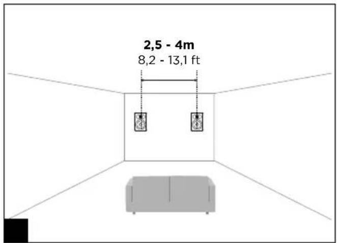
The loudspeakers should be positioned symmetrically, facing the listening area, ideally forming an equilateral triangle. The space between the two loudspeakers should measure from 8 to 13ft (2.5 to 4m) for a listening area of between 10 to 20ft (3 to 6m) (fig. 1). However, it is possible to vary these distances to find the ideal compromise depending on the particular layout of the room. The loudspeakers should be positioned at the same height, in the same horizontal plane (fig. 2).
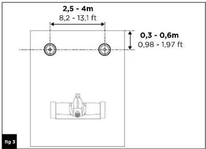
When used as in-ceiling loudspeakers, the left and right front loudspeakers should be placed in the same horizontal plane, 12 to 24 (30 to 60cm) away from the wall. The space between the left and right loudspeakers should measure from 8 to 13ft (2.5 to 4m) (fig. 3).
Used as a Home Cinema system (ceiling or wall)
- Front right, left and centre loudspeakers.
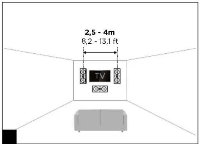
Used as in-wall loudspeakers, the left and right front loudspeakers should be positioned symmetrically on either side of the screen and half-way up, facing the listening area, and forming an equilateral triangle. The space between the two loudspeakers should measure from 8 to 13ft (2.5 to 4m) for a listening area of between 10 to 20ft (3 to 6m), approximately 20" (50cm) away from the screen. However, it is possible to vary these distances to find the ideal compromise depending on the particular layout of the room.
The centre loudspeaker should be as near to the screen as possible, either above or below the screen to ensure the realistic reproduction of dialogue (fig. 4).
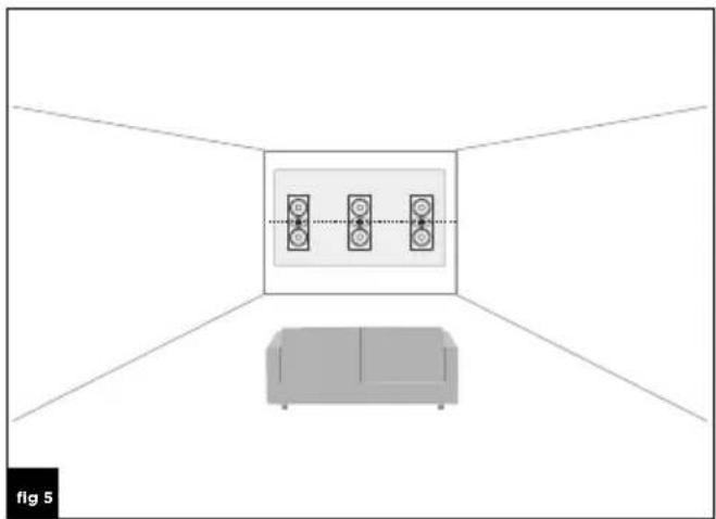
If using a micro-perforated projector screen (acoustically transparent), the left and right front loudspeakers and the centre loudspeaker should be placed half way up the screen, on the same horizontal plane behind the screen (fig. 5).
When used as in-ceiling loudspeakers, the left and right front loudspeakers and the centre loudspeaker should be placed in the same horizontal plane, 12 to 24" (30 to 60cm) away from the wall. The space between the left and right loudspeakers should measure from 8 to 13ft (2.5 to 4m) (fig. 6).
- Rear sound effects loudspeakers for 5.1 systems.
When used as in-wall loudspeakers, the rear sound effects loudspeakers should be installed in the side walls slightly behind the listening position (1 1/2 to 5ft / 0.5 to 1.5m), and at the same height as the left and right front loudspeakers (fig. 7).
When used as in-ceiling loudspeakers, the rear sound effects loudspeakers should be installed on the same horizontal plane, slightly behind the listening position (11/2 to 5ft / 0.5 to 1.5m), and the space between the left and right loudspeakers should measure from 8 to 13ft (2.5 to 4m) (fig. 8).
- Rear sound effects loudspeakers for 7.1 systems.
When used as in-wall loudspeakers, the left and right rear sound effects loudspeakers should be installed in the side walls on the same level as the listening position, and at the same height as the left and right front loudspeakers. The rear sound effects loudspeakers should be installed in the wall behind the listening position, and at the same height as the left and right front loudspeakers. The space between the two loudspeakers should measure from 8 to 13ft (2.5 to 4m) (fig. 9).
When used as in-ceiling loudspeakers, the left and right rear sound effects loudspeakers should be placed in the same horizontal plane at the same level as the listening position. The rear sound effects loudspeakers should be installed on the same horizontal plane, slightly behind the listening position (1 1/2 to 5ft / 0.5 to 1.5m), and the space between the two loudspeakers should measure from 5 to 8ft (1.5 to 2.5m) (fig. 10).
• Atmos sound effects loudspeakers (ceiling)
For a 5.1.2 system, the rear Atmos sound effects loudspeakers should be installed on the same horizontal plane, slightly in front of the listening position (1 1/2 to 5ft / 0.5 to 1.5m), and the space between the two loudspeakers should measure from 8 to 13ft (2.5 to 4m) (fig. 11).
For a 5.1.4 system, the front Atmos sound effects loudspeakers should be installed on the same horizontal plane, slightly in front of the listening position (1 1/2 to 5ft / 0.5 - 1.5 m), and the space between the two loudspeakers should measure from 8 to 13ft (2.5 to 4m). The rear Atmos sound effects loudspeakers should be installed on the same horizontal plane, slightly behind the listening position (1 1/2 to 5ft / 0.5 - 1.5 m), and the space between the two loudspeakers should measure from 8 to 13ft (2.5 to 4m) (fig. 12).
Installation
Existing construction
- Before installing your loudspeakers, make sure that there is nothing obstructing the ceiling/wall, such as air vents, and make sure that no cables will interfere with the installation. Use the appropriate tools to help you determine the correct location.
- Make sure there is enough space to install your product in the ceiling/wall.
- Trace the outline of the speaker driver on the ceiling/wall using the cutout template supplied. Cut along the trace using an appropriate tool to make a hole in the ceiling/wall (fig. 13).
- You can only install your loudspeakers once you have wired them up. Make sure you leave enough cable to allow you to wire up your loudspeakers with ease (approximately 20"/50cm).
We recommend using a cable with a marker in order to ensure the polarities of the speaker drivers are respected (+/-). Choose good quality cables with a wire gauge appropriate to their length: your retailer will be able to advise you.
- The loudspeaker fixes to the wall thanks to the rotating mounting brackets. Insert the loudspeakers into the opening and secure the mounting brackets by rotating them clockwise using a Phillips screwdriver or a screw-gun. If you use a screw-gun, make sure the tightening torque is set to a low value to prevent damaging the mounting brackets (fig. 14). The loudspeaker will be securely fixed in place when you feel resistance once tightened.
New constructions
- Use the specific optional mounting kit.
- Prepare the cables and make sure you leave enough cable to allow you to wire up your loudspeakers with ease (approximately 20"/50cm). We recommend using a cable with a marker in order to ensure the polarities of the speaker drivers are respected (+/-). Choose good quality cables with a wire gauge appropriate to their length: your retailer will be able to advise you.
- The loudspeaker fixes to the wall thanks to the rotating mounting brackets. Insert the loudspeakers into the opening and secure the mounting brackets by rotating them clockwise using a Phillips screwdriver or a screw-gun. If you use a screw-gun, make sure the tightening torque is set to a low value to prevent damaging the mounting brackets (fig. 15). The loudspeaker will be securely fixed in place when you feel resistance once tightened.
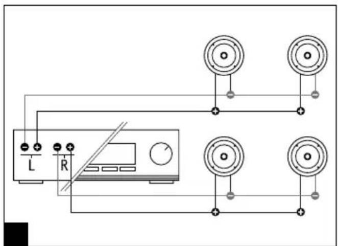
Wiring in parallel
The impedance of each product in the 100 SERIES range allows you to wire the loudspeakers in parallel to the same amplifier output (except for the 100 IWLCR 5 model) (fig. 16).
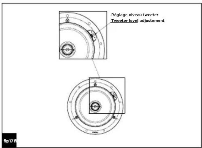
Adjusting the tweeter
The tweeter can be adjusted using the switch on the front of the loudspeaker as shown in the diagram (fig. 17).
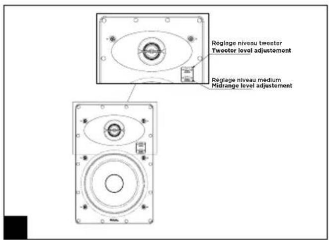
Adjusting the midrange (100 IW 6, 100 IWLCR 5)
The midrange can be adjusted using the switch on the front of the loudspeaker as shown in the diagram (fig. 18).
Orienting the tweeter (100 ICW 6, 100 ICW 8, 100 IW 6, 100 IWLCR 5, 100 ICLCR 5)
For the models 100 ICW 6, 100 ICW 8, 100 IW 6, 100 IWLCR 5 and 100 ICLCR 5, you can direct the tweeter towards the listening area for improved precision of the treble and of the stereo image (fig. 19).
ICW 6, ICW 8: angle of inclination from 0 to 20°, and 360° rotation.
IW 6, IWLCR 5, ICLCR 5: angle of inclination from 0 to 15°, and rotation on every axis.
Adjustment of the speaker mode (100 ICLCR5)
Adjust the speaker to "L" when it's used with the left speaker, "R" when it's used with the right speaker, and "C" when it's used with the central speaker (fig. 20).
Special precautions
Painting
If you wish to do so, you can paint the grilles of your 100 SERIES products so that they blend in perfectly with your interior. We recommend first removing the grille from the product and then painting it using a paint spraying device. You can use the same type of paint as the wall paint.
Break-in period
The speaker drivers used in the Integration 100 SERIES loudspeakers are complex mechanical assemblies which need a break-in period to operate at their best and to become acclimatised to the temperature and humidity of your environment. This break-in period varies depending on the conditions in question, and may take several weeks. To reduce this break-in period, we recommend operating your loudspeaker for about twenty consecutive hours. Once the loudspeaker's characteristics have totally stabilised, you will be able to enjoy the full potential of your Integration 100 SERIES loudspeakers.
Conditions of warranty
Please contact your Focal retailer if you encounter any problems.
The warranty in France for any Focal product is valid for 2 (two) years from the date of purchase, and rights are non-transferable in case of resale. In the case of defective equipment, the equipment must be shipped at your expense in its original packaging to the dealer who will test the equipment in order to determine the nature of the fault. If the product is still under warranty, the product will be returned to you or replaced, shipping pre-paid. If the product is no longer under warranty, you will be given a quote for the repairs.
The warranty does not cover damage resulting from improper use or incorrect wiring (e.g. burnt out moving coils, for example).
Outside of France, Focal products are covered by a warranty whose conditions are determined locally by the official Focal dealer in each country, in compliance with the laws in force in the respective territory.
Uso Home Cinema (Techo o pared)
5 ICLCR و 5 IWLCR و IW
Your Focal-JMlab product was developed and manufactured with high-quality materials and components which can be recycled and/or re-used. This symbol indicates that electrical and electronic equipment must be disposed of separately from normal garbage at the end of its operational lifetime. Please dispose of this product by bringing it to your local collection point or recycling centre for such equipment. This will help to protect the environment in which we all live.
- SERIES
- Package contents
- Key features
- Choice of amplifier
- Positioning the loudspeakers
- Used for a public address system (ceiling)
- Used as a stereo system (ceiling or wall)
- Used as a Home Cinema system (ceiling or wall)
- Installation
- Existing construction
- New constructions
- Wiring in parallel
- Adjusting the tweeter
- Adjusting the midrange (100 IW 6, 100 IWLCR 5)
- Orienting the tweeter (100 ICW 6, 100 ICW 8, 100 IW 6, 100 IWLCR 5, 100 ICLCR 5)
- Adjustment of the speaker mode (100 ICLCR5)
- Special precautions
- Painting
- Break-in period
- Conditions of warranty
- Uso Home Cinema (Techo o pared)
Brand : FOCAL
Model : 100 IC 6-ST
Category : Loudspeaker