
ST12 - Vacuum Cleaner Cotech - Free user manual and instructions
Find the device manual for free ST12 Cotech in PDF.


| Product Type | Vacuum Cleaner |
| Brand | Cotech |
| Model | ST12 |
| Dust Collection | Bagless |
| Dustbin Capacity | 1.5 L |
| Motor Power | 800 W |
| Suction Power | 200 AW |
| Filtration | HEPA 13 |
| Noise Level | 75 dB |
| Cord Length | 6 m |
| Weight | 5.5 kg |
| Dimensions (L x W x H) | 30 x 25 x 40 cm |
| Accessories Included | Crevice tool, upholstery brush, floor nozzle |
| Adjustable Suction | Yes (2 levels) |
| Automatic Cord Rewind | Yes |
| Washable Filter | Yes |
| Power Cord Type | Mains powered |
| Color | Red/Black |
| Operation | Upright |
Frequently Asked Questions - ST12 Cotech
User questions about ST12 Cotech
0 question about this device. Answer the ones you know or ask your own.
Ask a new question about this device
Download the instructions for your Vacuum Cleaner in PDF format for free! Find your manual ST12 - Cotech and take your electronic device back in hand. On this page are published all the documents necessary for the use of your device. ST12 by Cotech.
USER MANUAL ST12 Cotech
Read the entire instruction manual carefully and make sure that you fully understand it before you use the equipment. Keep the manual for future reference.
Viktig information:
natural_image
Technical line drawing of a manual cutting machine with a saw blade and handle (no text or symbols)ART.NO
40-8280
MODEL
ST12
Ver. 20130827
Original instructions
Bruksanvisning i original
Please read the entire instruction manual before use and save it for future reference. We reserve the right for any errors in text or images and for making any necessary technical changes to this document. If you should have any questions concerning technical problems please contact our Customer Services.
Safety
• Make sure that everyone who operates the table saw has read and understood the safety instructions.
- The table saw must only be used if it is functioning correctly. Carefully observe all the warnings and safety instructions outlined in this manual. Ensure that there are no disturbances that may affect workplace safety.
- Ensure that all safety devices are in place when the table saw is used.
• Only use saw blades which conform to EN 847-1.
- Keep all the table saw's safety instructions accessible and in readable condition.
• Make sure that the table saw is standing on a solid foundation.
- Check that none of the electrical cables are damaged and that they are all properly connected.
- Keep children away from the table saw when it is connected to the power supply.
- This product must not be used by anyone (including children) suffering from physical or mental impairment. This product should not be used by anyone who has not read the instruction manual unless they have been instructed in its use by someone who will take responsibility for their safety.
- Operators of the table saw must not be distracted.
- If a second person is working next to the table saw to take care of workpieces, the table saw must be equipped with a table extension. The second person must never stand anywhere but at the end of the extension table.
- Keep the working area tidy. Cluttered surfaces and benches invite accidents.
- Wear suitable attire. Do not wear loose-fitting clothing or jewellery; they could be caught in moving parts. Non-slip shoes are recommended for outdoor work. Wear a hairnet or similar if you have long hair.
• Always use safetywear. Wear safety glasses. Use a dust mask or dust filter when working in dusty environments.
• Make sure the blade is fitted the right way round.
- The table saw's safety devices must not be removed or disabled.
- Disconnect the table saw from the power supply before servicing, changing attachments, changing blades or cleaning the table saw or measuring any workpiece placed on it.
- Disconnect the table saw from the power supply before correcting any potential hazards.
- Dust extraction equipment must be used when creating large amounts of dust.
- Never use blades which are defective, blunt or of the incorrect size.
• High speed steel blades must not be used.
- The riving knife is an important safety device which steers the workpiece and prevents the blade for binding in the cut and the workpiece from kicking back.
• The blade guard must always be in place when making a cut.
• The blade guard must be horizontal over the saw blade.
- Always use a push stick when rip-cutting narrow stock i.e. thinner than 120 mm. The push stick prevents hands from coming too close to the saw blade.
- Replace the table insert if it is damaged in any way.
- Switch off the motor and disconnect the table saw from the power supply before leaving the workplace.
- Disconnect the table saw from the power supply before moving it. Make sure that the table saw is connected correctly before switching it on.
• Servicing and repair work must only be carried out at an authorized service centre.
- All safety devices and guards must be replaced immediately following any repairs or servicing.
• Never let children play with the product.
- Never use the table saw if you are tired or under the influence of drugs, alcohol or medication.
Specific safety rules
- If the accompanying stand is not used, the table saw must be placed level on a stable, table-like platform. The working height must be at least 800 mm.
- When sawing, always stand in front of the table saw and to the left of the saw blade.
- Keep the work area free from foreign objects and potential hazards.
- Inspect the workpiece for nails and screws and remove them before starting to cut.
• This table saw is designed exclusively for sawing wood or similar material.
• Only genuine parts and accessories may be used.
Despite the fact that the table saw has been fitted with all the necessary safety devices and conforms to relevant safety standards, the following hazards still exist
- Danger to fingers and hands from the rotating blade if the workpiece is not handled properly.
- Danger of the workpiece being ejected because it binds or is guided incorrectly.
- Danger to hearing due to loud noise if the work exceeds the permitted noise level. Personal protective equipment such as ear defenders must be used at all times.
- Danger caused by a defective saw blade. Regular checks should be made to make sure that the blade is intact.
• Danger of electrocution if an incorrect mains lead is used. - Whenever accessories are used, their instruction manuals must also be read and followed to ensure that they are used in the correct way.
• No matter how many precautions one takes there is still the risk of unforeseen hazards. - The chances of an accident occurring can be minimized by adhering to the safety instructions listed above.
Guide to Safety Symbols

Read the entire instruction manual.

Always use ear protection.

Always use safety glasses.
Assembly
Note: Make sure that the saw is disconnected from the power supply before assembly, adjustment or servicing.
Legs

- Lay the tabletop (1) onto a workbench and remove the wrapping (a) from around the motor.
natural_image
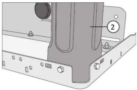
Technical diagram of a mechanical assembly with labeled component (2), showing mounting flanges and housing (no text or symbols beyond labels)- Attach the 4 legs (2) using the supplied M6 × 16 mm bolts, M6 nuts and washers. 2 bolts hold each leg in place. Finger-tighten the bolts.
On/off switch
Attach the on/off switch (3) to the tabletop using 2 of the M6 × 16 mm bolts, M6 nuts and washers.

Cross members
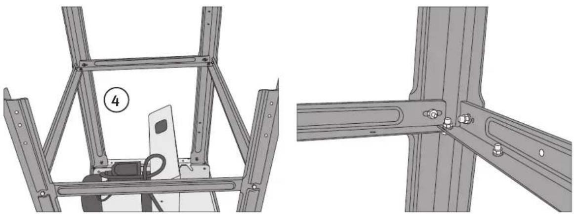
Fit the cross members (4), 2 long and 2 short, to the legs using 12 of the M6 × 16 mm bolts with nuts and washers. Finger-tighten the bolts.
natural_image
Technical illustration of a metal frame structure with two views showing internal components and mounting hardware (no text or symbols)Table extension
Attach the table extension (6) using the two struts (5) and the cross brace inside it. Use 6 of the M6 × 16 mm bolts with nuts and washers. Finger-tighten the bolts. The table extension can also be attached to the side of the table to widen it. In this case, the shorter struts should be used.

Dust extraction port
Attach the dust extraction port (7) to the lower blade guard using 4 of the M6 × 16 mm bolts, M6 nuts and washers.
Wheels
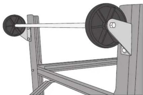
- Attach the wheels to the back legs using 4 of the M6 × 16 mm bolts, M6 nuts and washers. Finger-tighten the bolts.
- Turn the table saw the right way up. Make sure that all the legs are touching the ground. Tighten all the nuts and bolts except for those in the wheels.
- Adjust the height of the wheels so that they just touch the ground. Tighten their nuts and bolts.

natural_image
Mechanical setup showing a pulley system mounted on a frame with two wheels (no text or symbols visible)Riving knife
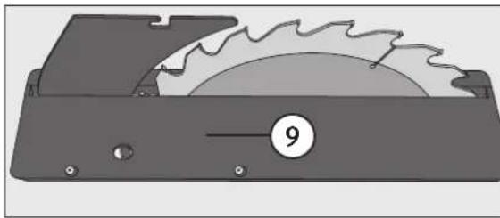
- Remove the table insert (9).
natural_image
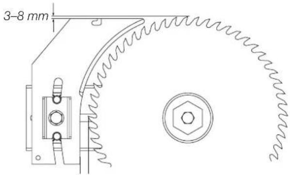
Technical illustration of a saw cutting machine with a labeled circular component (no text or symbols beyond the number 9)- Adjust the riving knife (10) as shown in the diagram. Loosen the adjusting screw (11) a little so you can adjust the knife. Retighten the screw. Refit the table insert.

Blade guard
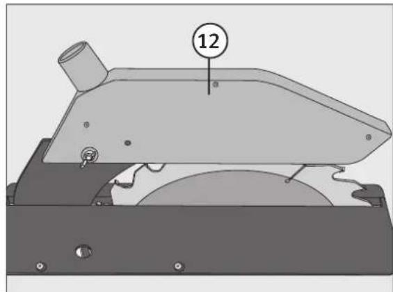
Bolt the blade guard (12) onto the riving knife using the M6 × 25 mm bolt, M6 washer and the wing nut.
natural_image
Mechanical component diagram showing a cutting tool with a numbered callout (12), no visible text or symbolsHose holder
Attach the hose holder (14) to the tabletop using 2 of the M6 × 16 mm bolts, M6 nuts and washers. Connect the dust extraction hose (13) to the blade guard and to the dust extraction port and then tidy the hose up by pushing it into the hose holder.

Accessory hook
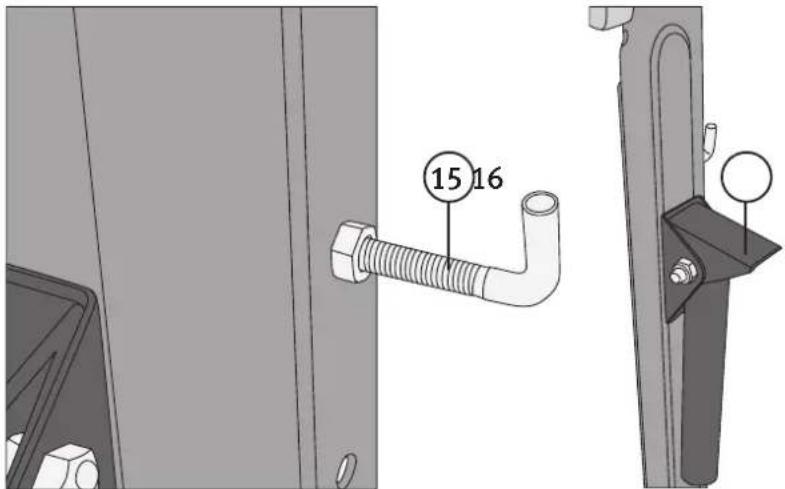
Attach the accessory hook (15) for hanging the blade spanner and push stick on to the outside of the right front leg using 2 of the M6 nuts and washers (one nut on the inside of the leg and one on the outside).
Transportation handles
Attach the two folding transportation handles (16) to the face of the front legs using 4 of the M6 × 16 mm bolts, M6 nuts and washers.
Rip fence
- To attach the rip fence rail to the table you will first need to bolt the clamp (17) to the tabletop. Bolt one of the rip fence clamp's holders to the tabletop using an M6 × 30 mm socket head bolt, nut and washer and then slide the pin on the end of the clamping handle into the hole in the holder.
-
Then bolt the other clamp holder onto the tabletop using the other M6 × 30 mm socket head bolt, nut and washer.
-
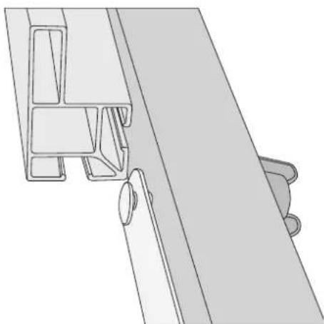
Attach the rip fence to the rip fence rail (19) by sliding it onto the slider plate (18) which is bolted on using two M6 × 50 mm coach bolts, washers and wing nuts.

natural_image
Technical line drawing of a mechanical bracket or panel assembly (no text or symbols)- The rip fence (20) can be mounted in two positions, low profile


natural_image
Technical line drawing of a mechanical assembly with no visible text or symbolsor high profile. Secure the rip fence to the rail by tightening the wing nuts.
- Locate the end of the rip fence rail in the clamp (17). Lift the clamping handle up to lock the rip fence rail in position and push the handle down to release it.

natural_image
Mechanical assembly diagram showing a motor with wheels and a numbered component (17), no readable text or symbols present.Mitre gauge

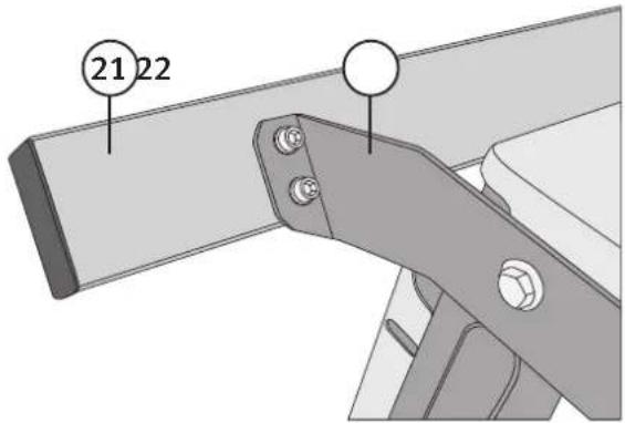
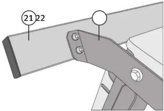
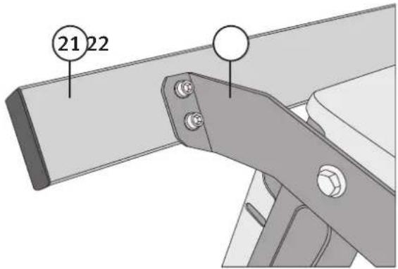
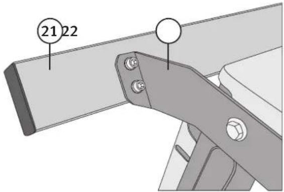
- Attach the two slider rail brackets (22) to the slider rail (21) using four M6 × 16 mm socket head bolts and washers.
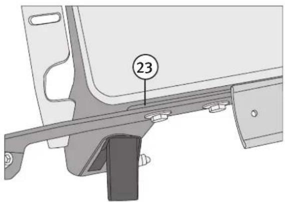
- Attach the slider rail to the table using four M6 × 20 mm bolts, nuts and washers. Finger-tighten the bolts. Note: Insert the spacer (23) between the table and the front slider rail bracket.
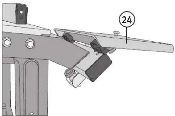
- Slide the mitre gauge table (24) onto the slider rail. Insert an M6 × 40 mm socket head bolt (25) and wing nut at each end of the slider rail. These will prevent the sliding mitre gauge table from coming off.

natural_image
Mechanical assembly diagram showing a bracket with a numbered component (25) and mounting base (no text or symbols present)
natural_image
Technical diagram of a mechanical assembly with labeled component 26 (no text or symbols beyond label)-
Adjust the lower bearing (26) on the mitre gauge table so the table can slide freely but not too loosely.
-
Align the sliding mitre table so that it is parallel to and level with the tabletop. Adjust it by moving the slider rail. Extend the mitre gauge fence to check that the two tables are level. When the slider rail has been adjusted, the four bolts (30) can be tightened. The two wing nuts (29) on the mitre gauge can be used for fine-adjustments.
-
Set the mitre gauge at 90° to the saw blade by swivelling it up to the cam head bolt (31) in the corner of the mitre table. Check that the mitre gauge is at right angles by placing a try square against the saw blade. If necessary, adjust the cam head bolt by undoing the nut under the mitre table. Test the angle on a piece of waste stock and fine-adjust if necessary.

- When attaching the mitre gauge (27) to the sliding table, place the two plastic washers (28) between them. Finger-tighten the bolt nearest the table saw so the gauge can swing round. Tighten the other bolt which is attached to the locking handle so that the mitre gauge is locked in position when the handle is depressed and can swing round when the handle is lifted.


natural_image
Technical line drawing of a mechanical assembly with no visible text or symbolsElectrical connections
• The power supply must be 230 V AC, 50 Hz.
• The mains lead and any extension leads used must 3-core (twin and earth).
• The cablage must have a conductor cross-sectional area of 1.5 mm^2 .
• Use a standard (BS1363) plug fitted with a 13 amp fuse.
Note: All electrical connections and repairs should be carried out by a qualified electrician.
Use
Placement
- Place the saw on a firm and level surface.
• The table legs have holes in the bottom for bolting to the floor if required.
• Make sure that there is enough space around the saw for the work to be carried out safely. - Never lift the table saw up by the tabletop, always use a sack truck, pallet truck or suitable lifting equipment.
Fitting and replacing the saw blade
Blade height setting
The saw blade can be raised and lowered over a range of 80~mm with the help of the elevating and lowering handle (32).

natural_image
Mechanical assembly diagram showing a motor, pulley, and cable (no text or symbols)Setting the bevel angle
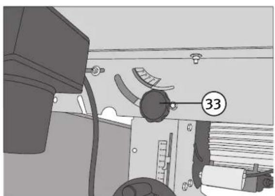
- After first undoing the locking knobs (33, 34) on the front and back of the table saw, the saw blade can be bevelled freely from 90^ to 45^ .
natural_image
Interior view of a vehicle or industrial equipment unit with mechanical components and a numbered label (33), no readable text or symbols present.
- Set the desired bevel angle and then tighten the locking knobs.
Changing the blade
Note: Carefully observe the direction of rotation markings on the saw blade.
- Make sure the saw is switched off and unplugged.

natural_image
Technical illustration of a mechanical assembly with a cutting tool and workpiece (no text or symbols)
natural_image
Technical illustration of a mechanical cutting machine with visible blades and central blade (no text or symbols)-
Remove the blade guard. 3. Unscrew the four table insert retaining screws and remove the insert.
-
Raise the saw blade as high as it will go and undo the blade locking nut using the supplied spanner. Note: The nut has a left-hand thread.

natural_image
Illustration of a hand operating a mechanical cutter tool on a workbench (no text or symbols visible)- Remove the flange and the blade.
- Fit the new blade and replace the flange making sure that the lugs on the flange fit into the slots on the spindle. Tighten the nut securely.
- Check the riving knife setting and adjust it if necessary.
- Refit the table insert and the blade guard.
Sawing
Note: Always test the saw blade on a suitable workpiece following a change of blade. Check that all the angles are correct and that the saw cut is clean. Adjust if necessary. A bit of practice is usually needed to achieve the perfect result. Try sawing different types of wood and different rates of feed and practice changing the settings safely until you feel comfortable using the saw. Always use the supplied push stick if necessary.
Note: Keep your hands well away from the blade.
Ripping (parallel cutting)
• Always use the rip fence for sawing parallel along the length of the workpiece.
• Use the high profile edge of the rip fence for workpieces over 120 mm in height.
• Use the low profile edge of the rip fence for workpieces under 120 mm in height.
Crosscutting
Always use the mitre gauge for square crosscutting, mitre crosscutting or bevel crosscutting.
Note: The blade guard in the pictures has been removed only for the purposes of allowing a clearer view of the method of operation or construction.
Sawing wide workpieces
- Set the rip fence.
- Make sure that your left hand is resting on a firm surface to steady you. If narrow offcuts are produced during the sawing, the workpiece may only be fed through the blade using your right hand or with the help of a push stick.
Sawing narrow workpieces
- Set the rip fence.
- Feed the workpiece through the blade with both hands.
- When your hands begin to near the blade, you should use a push stick to feed the workpiece past the blade in a steady motion.
Sawing edging and moulding
- Set the rip fence to the low profile.
- Feed the workpiece into the blade using the push stick until the edge of the workpiece is in the area of the riving knife.
- Make sure that long workpieces do not fall onto the floor after sawing by attaching a table extension onto the table.
Crosscutting narrow workpieces
Use the mitre gauge to guide you whenever making any kind of crosscut.
Note: Never remove offcuts from around the saw blade with your hands.
Sawing bevels, grooves, rebates, etc
- When ripping a bevel, the cut should be made so that the cut-off strip falls away from the main workpiece on the opposite side of the blade to the rip fence.
- When cutting grooves or rebates, remove the blade guard and lower the saw blade to the desired height. Make sure that the workpiece can be fed over the blade without difficulty.

natural_image
Diagram of a hand operating a mechanical device with a wooden base and railings (no text or symbols)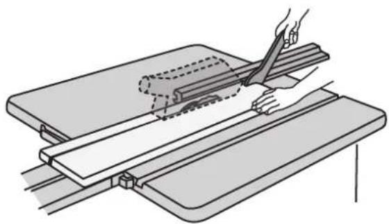
natural_image
Illustration of a hand using a tool to cut or spread a piece on a flat surface, with no text or symbols present.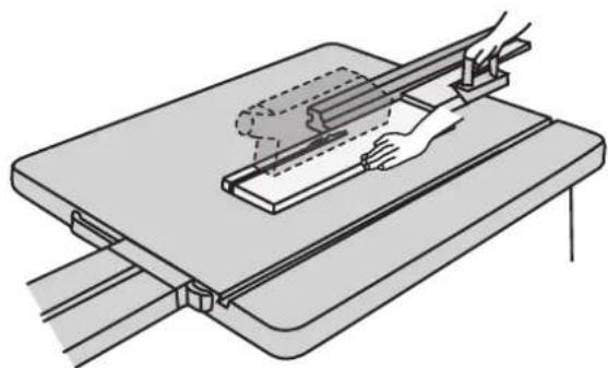
natural_image
Diagram of a mechanical assembly with hands operating a tool on a flat base (no text or symbols)
natural_image
Illustration of a hand using a tool to cut or spread a machine component (no text or symbols visible)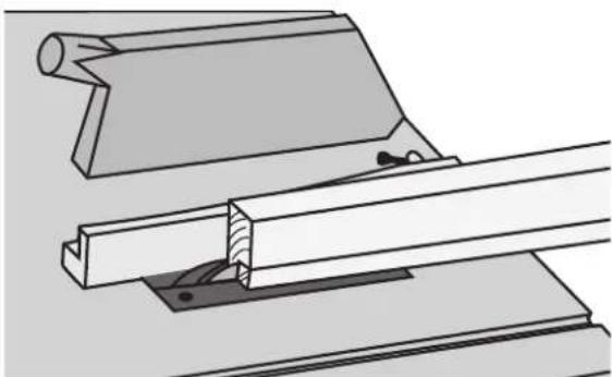
natural_image
Technical line drawing of a mechanical assembly with two components (no text or symbols)Length stop
The mitre guage fence has a length stop for making repetitive cuts of the same length.

natural_image
Technical line drawing of a mechanical assembly with no visible text or symbolsTroubleshooting guide
| The motor does not start. • Saw not | plugged in.• Is the wall socket live?• Is the mains lead /extension lead damaged or disconnected?• Has the motor overheated and tripped the thermal fuse?Let the motor cool down and then try it again.• Defective switch. |
| Saw makes unsatisfactory cuts. • The blade is blunt, change it.• Check that the blade is not mounted backwards. | |
| Material pinches blade when ripping. • | Riving knife not aligned correctly with blade.• Warped wood, edge against fence not straight.• Feed the entire workpiece past the blade before letting go of it(use a push stick if necessary). Inspect the saw blade, change if necessary. |
| Material builds up on the riving knife. | • Check/adjust the riving knife so that it is in line with the saw blade, make sure that the kerf of the blade is not narrower than the riving knife; change the blade if it is too thin. |
| The workpiece or parts of it are thrown backwards. | • The rip fence is not parallel with the saw blade, adjust.• Check/adjust the riving knife so that it is in line with the saw blade. Feed the entire workpiece past the blade before letting go of it(use a push stick if necessary).• Inspect the saw blade regularly, change if necessary. |
| The saw blade cannot be tilted without the use of force. | • Use a brush and vacuum cleaner to remove all sawdust from the adjustment mechanisms, then carefully lubricate. |
| Heavy vibrations. • Check that all bolts and nuts are secure and tight.• Make sure that the blade is not damaged and is fitted correctly.• Make sure that the table saw is on a flat level surface and that all four legs are on the ground. Reposition or fasten to floor if necessary. | |
| The motor stops or the workpiece gets burn marks when ripping. | • The blade is blunt, change it.• Use a slower feed rate.• Check/adjust the riving knife so that it is in line with the saw blade. |
Care and maintenance
Note: Switch the table saw off and unplug it before carrying out any repairs or adjusting any settings.
• Always keep the instruction manual together with the machine.
- Keep the working area tidy.
- Wear eye protection when cleaning.
- Do not clean the plastic components of the table with strong detergents. A mild detergent on a moist cloth is recommended. Never pour water onto the table saw.
- Check the condition of the saw blade regularly. Do not use saw blades that are blunt, damaged or deformed.
- Replace the table insert as soon as it is worn. Keep the tabletop free of resin.
- Remove sawdust frequently to prevent blockages and fire hazards.
Disposal
This product should be disposed of in accordance with local regulations. If you are unsure how to proceed, contact your local authority.
Specifications
Voltage 230 V, 50 Hz
Power 2200 W
Duty cycle S6/40%
Speed 2800 rpm
Saw blade 315 × 30 × 3.6/2.0 Z24
Extraction port 100 mm
Blade tilt 90°–45°
Depth of cut 80 mm/90°, 48 mm/45°
Table size 800 × 550 mm
Table extension size 800 × 400 mm
Working height 800 mm
Weight 46 kg
Bordscirkelsåg
ART.NR 40-8280 MODELL ST12
natural_image
Technical diagram of a mechanical assembly with labeled component (2), showing mounting flanges and a central vertical component (no text or symbols beyond label)Stag
natural_image
Technical diagram of a metal frame structure with labeled component 4, showing two views (top and side) without any readable text or symbols.Förlängningsskiva
Utsugsstosen
natural_image
Mechanical setup showing a pulley system mounted on a frame with two wheels (no text or symbols visible)Klyvkil
natural_image
Diagram of a mechanical disc with serrated edge and labeled part (9), no readable text or symbols presentnatural_image
Mechanical component diagram showing a cylindrical part inserted into a housing, with no visible text or symbols.Slanghållare
Förvaringskrok
natural_image
Technical line drawing of a mechanical bracket or panel assembly with no visible text or symbolsnatural_image
Technical line drawing of a mechanical component with no visible text or symbolsnatural_image
Mechanical assembly diagram showing a motor with wheels and a numbered component (17), no readable text or symbols present.Geringslinjal
natural_image
Mechanical assembly diagram showing a bracket with a numbered component (25) and mounting base (no text or symbols present)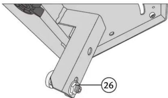
natural_image
Technical diagram of a mechanical assembly with labeled component 26 (no text or symbols beyond label)natural_image
Technical diagram of a mechanical assembly with no visible text or symbolsElektrisk anslutning
natural_image
Mechanical assembly diagram showing a wheel and motor components with no visible text or symbolsnatural_image
Interior view of a vehicle or industrial equipment with mechanical components and a numbered label (33), no readable text or symbols present.
natural_image
Technical illustration of a mechanical assembly with a cutting tool and base plate (no text or symbols)
natural_image
Technical illustration of a mechanical assembly with cutaway view of components like saw and blades (no text or symbols)natural_image
Illustration of a hand operating a saw cutting machine with visible blades and gears (no text or symbols)natural_image
Diagram of a hand operating a mechanical assembly with rollers and a wooden block (no text or symbols)
natural_image
Illustration of a hand cutting through a wooden plank using scissors (no text or symbols)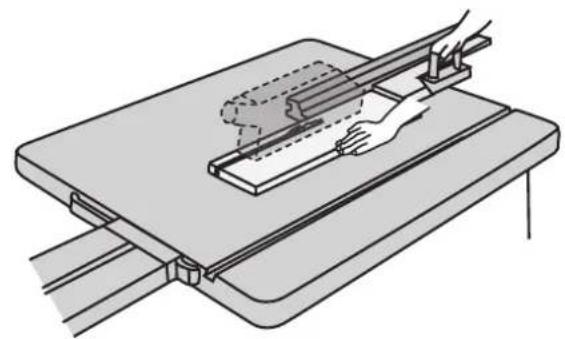
natural_image
Technical line drawing of a mechanical assembly with hands operating a workpiece (no text or symbols)
natural_image
Illustration of a hand using a tool to cut or spread a machine component (no text or symbols visible)
natural_image
Technical line drawing of a mechanical assembly with two components (no text or symbols)Längdstopp
natural_image
Technical line drawing of a mechanical assembly with no visible text or symbolsFelsökningsschema
natural_image
Technical diagram of a mechanical assembly with labeled component (2), showing mounting flanges and a central vertical component (no text or symbols beyond label)natural_image
Technical diagram showing two views of a metal frame structure with labeled component 4 (no text or symbols beyond the number)Forlengelsesplate
Utsugerstussen
Utsugerstussen (7) monteres på det nedre sagklinge- vernet (8) med 4 stk. M6 × 16 skruer, M6 skiver og mutre.

Hjul
natural_image
Mechanical lifting device with two pulleys mounted on a frame (no text or symbols visible)Klyvekile
natural_image
Diagram of a saw cutting machine with a labeled circular component (number 9), showing blade and edge details without any text or symbols.natural_image
Mechanical component diagram showing a cutting machine with a numbered part (12) and mounting holes, no readable text or symbols present.Slangeholder
Krok for oppbevaring
natural_image
Technical line drawing of a mechanical bracket or panel assembly (no text or symbols)- Skyv deretter på anslagsskinnen (20) for enten lav

natural_image
Technical line drawing of a mechanical component with no visible text or symbolsnatural_image
Mechanical assembly diagram showing a motor with wheels and a numbered component (17), no readable text or symbols present.Gjæringslinjal
- Monter begge holderne (22) på styreskinnen (21). Bruk 4 stk. M6 × 16 innvendig sekskantskruer og skiver.

natural_image
Mechanical assembly diagram showing a bracket with a numbered component (25) and mounting base (no text or symbols present)
natural_image
Technical diagram of a mechanical assembly with labeled component 26 (no text or symbols beyond label)natural_image
Technical diagram of a mechanical assembly with no visible text or symbolsElektrisk tilkobling
• Nettspenningen skal være 230 V, 50 Hz.
- Strømtilkoblingsledning og ev. skjøteledning må ha 3 ledere.
- Skjøteledningen må ha en area på minst 1,5 mm ^2 .
- Sikringen på strømkretsen skal være maks 16 A.
natural_image
Mechanical assembly diagram showing a motor, pulley, and cable (no text or symbols)natural_image
Interior view of a vehicle or industrial equipment unit with mechanical components and a numbered label (33), no readable text or symbols present.
natural_image
Mechanical assembly diagram showing a motor, gear, and housing with a numbered component (34) on the side (no text or symbols beyond the number)natural_image
Technical illustration of a mechanical assembly with a cutting tool and workpiece (no text or symbols)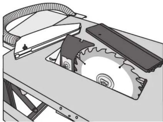
natural_image
Technical illustration of a mechanical assembly with cutaway view of a saw cutting machine (no text or symbols)natural_image
Illustration of a hand operating a mechanical cutter tool on a workbench (no text or symbols visible)natural_image
Diagram of a hand operating a mechanical device with a wooden base and railings (no text or symbols)
natural_image
Illustration of a hand using a tool to cut or spread a piece on a flat surface, with no text or symbols present.
natural_image
Diagram of a mechanical assembly with hands operating a tool on a flat base (no text or symbols)
natural_image
Illustration of a hand using a tool to cut or spread a machine component (no text or symbols visible)
natural_image
Technical line drawing of a mechanical assembly with two components, no text or symbols presentLengdestopper
Bruk gjærelinjalens lengdestopper när flere emner skal kappes like lange.

natural_image
Technical line drawing of a mechanical assembly with no visible text or symbolsFeilsøking
Sagklinge 315 × 30 × 3,6/2,0 Z24
Koblingsstuss 100 mm
Vinkling 90°- 45°
natural_image
Technical diagram of a mechanical assembly with labeled component (2), showing mounting flanges and a central vertical component (no text or symbols beyond label)Tuet
natural_image
Technical diagram showing two views of a metal frame structure with labeled components (no text or symbols present)Pidennyskappale
Pölynpoistoliitäntä
natural_image
Mechanical setup showing a pulley system mounted on a frame with two wheels (no text or symbols visible)Halkaisukiila
natural_image
Diagram of a mechanical disc with serrated edge and labeled part (9), no readable text or symbols presentSäilytyskoukku
natural_image
Technical line drawing of a mechanical bracket or panel assembly with no visible text or symbolsnatural_image
Technical line drawing of a mechanical component or bracket assembly (no text or symbols)natural_image
Mechanical assembly diagram showing a motor with wheels and a numbered component (17), no readable text or symbols present.Jiiriohjain
natural_image
Mechanical assembly diagram showing a bracket with a numbered component (25) and a separate bracket with bolts (no text or symbols present)
natural_image
Technical diagram of a mechanical assembly with labeled component 26 (no text or symbols beyond label)natural_image
Technical line drawing of a mechanical assembly with no visible text or symbolsnatural_image
Mechanical assembly diagram showing a motor, pulley, and cable connections (no text or symbols)Jiirikulman säätö
natural_image
Interior view of a vehicle or industrial equipment unit with mechanical components and a numbered label (33), no readable text or symbols present.
natural_image
Technical illustration of a mechanical assembly with a cutting tool and base plate (no text or symbols)
natural_image
Technical illustration of a mechanical cutting machine with visible blades and central blade (no text or symbols)natural_image
Illustration of a hand operating a mechanical machine with gears and blades (no text or symbols)natural_image
Diagram of a hand operating a mechanical device with a wooden base and railings (no text or symbols)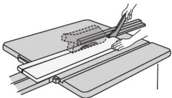
natural_image
Illustration of a hand cutting through a wooden plank using scissors (no text or symbols)
natural_image
Technical illustration of a mechanical assembly with hands operating a workpiece (no text or symbols present)
natural_image
Illustration of a hand using a tool to cut or spread a machine component (no text or symbols visible)
natural_image
Technical line drawing of a mechanical assembly with two components, no text or symbols presentPituuspysäytin
natural_image
Technical line drawing of a mechanical assembly with mounting brackets and a bracket (no text or symbols)Vianhakutaulukko
natural_image
Technical diagram of a mechanical assembly with labeled component (2), showing mounting flanges and bolted joints (no text or symbols beyond labels)Verstrebung
natural_image
Technical diagram of a metal frame structure with labeled components, showing two views (top and side) without any readable text or symbols.Verlängerungsplatte
Absaugstutzen
natural_image
Mechanical lifting device with two pulleys and a lever (no text or symbols visible)Spaltkeil
natural_image
Diagram of a mechanical disc with serrated edge and labeled part (9), no readable text or symbols presentnatural_image
Mechanical component diagram showing a cylindrical part inserted into a housing, with no visible text or symbols.Schlauchhalterung
Aufbewahrungshaken
natural_image
Technical line drawing of a mechanical bracket or panel assembly with no visible text or symbolsnatural_image
Technical line drawing of a mechanical assembly with no visible text or symbolsnatural_image
Mechanical assembly diagram showing a motor with wheels and a numbered component (17), no readable text or symbols present.Gehrungslineal
natural_image
Technical diagram of a mechanical bracket with a numbered component (25) and mounting base, no readable text or symbols present.
natural_image
Technical diagram of a mechanical assembly with labeled component 26 (no text or symbols beyond label)
natural_image
Technical line drawing of a mechanical assembly with no visible text or symbolsStromanschluss
natural_image
Mechanical assembly diagram showing a wheel and motor components with no visible text or symbolsnatural_image
Interior view of a vehicle or industrial equipment unit with mechanical components and a numbered label (33), no readable text or symbols present.
natural_image
Technical illustration of a mechanical assembly with a cutting tool and base plate (no text or symbols)
natural_image
Technical illustration of a mechanical cutting machine with visible blades and central blade (no text or symbols)natural_image
Illustration of a hand operating a saw cutting machine with a blade and gear (no text or symbols)natural_image
Technical illustration of a mechanical assembly with hands operating a workpiece (no text or symbols present)
natural_image
Illustration of a hand using scissors to cut or spread a piece of wood on a cutting board (no text or symbols)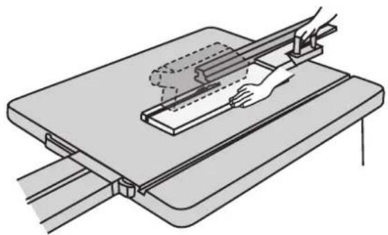
natural_image
Technical line drawing of a mechanical assembly with a hand operating a workpiece (no text or symbols present)
natural_image
Illustration of a hand using a tool to cut or spread a machine component (no text or symbols visible)
natural_image
Technical line drawing of a mechanical assembly with two components (no text or symbols)Längenanschlag
natural_image
Technical line drawing of a mechanical assembly with no visible text or symbolsFehlersuche
Declaration of Conformity
Klas Balkow President
Insjön, Sweden, 2011-11-11
SVERIGE
KUNDTJÄNST
Tel:
0247/445 00
Fax:
0247/445 09
E-post: kundservice@clasohlson.se
INTERNET
www.clasohlson.se
BREV Clas Ohlson AB, 793 85 INSJÖN
NORGE
KUNDESENTER
Tlf.:
23 21 40 00
Faks:
23 21 40 80
E-post: kundesenter@clasohlson.no
INTERNETT
www.clasohlson.no
POST
Clas Ohlson AS, Postboks 485 Sentrum, 0105 OSLO
SUOMI
ASIAKASPALVELU
Puh.: 020 111 2222
10 – 13 Market Place
Kingston Upon Thames
Surrey
KT1 1|Z
DEUTSCHLAND
KUNDENSERVICE


- Safety
- Specific safety rules
- Despite the fact that the table saw has been fitted with all the necessary safety devices and conforms to relevant safety standards, the following hazards still exist
- Guide to Safety Symbols
- Assembly
- On/off switch
- Cross members
- Table extension
- Dust extraction port
- Wheels
- Riving knife
- Blade guard
- Hose holder
- Accessory hook
- Transportation handles
- Rip fence
- Electrical connections
- Use
- Placement
- Fitting and replacing the saw blade
- Blade height setting
- Setting the bevel angle
- Changing the blade
- Sawing
- Ripping (parallel cutting)
- Crosscutting
- Sawing wide workpieces
- Sawing narrow workpieces
- Sawing edging and moulding
- Crosscutting narrow workpieces
- Sawing bevels, grooves, rebates, etc
- Length stop
- Care and maintenance
- Disposal
- Specifications
- Bordscirkelsåg
- ART.NR 40-8280 MODELL ST12
- Stag
- Förlängningsskiva
- Utsugsstosen
- Klyvkil
- Slanghållare
- Förvaringskrok
- Elektrisk anslutning
- Längdstopp
- Forlengelsesplate
- Utsugerstussen
- Hjul
- Klyvekile
- Slangeholder
- Krok for oppbevaring
- Elektrisk tilkobling
- Lengdestopper
- Tuet
- Pidennyskappale
- Pölynpoistoliitäntä
- Halkaisukiila
- Säilytyskoukku
- Jiiriohjain
- Jiirikulman säätö
- Pituuspysäytin
- Verstrebung
- Verlängerungsplatte
- Absaugstutzen
- Spaltkeil
- Schlauchhalterung
- Aufbewahrungshaken
- Stromanschluss
- Längenanschlag
- Declaration of Conformity
- SVERIGE
- NORGE
- SUOMI
- DEUTSCHLAND
Brand : Cotech
Model : ST12
Category : Vacuum Cleaner