CMS 803 - Högtalare TANNOY - Gratis bruksanvisning och manual
Hitta enhetens manual gratis CMS 803 TANNOY i PDF-format.

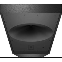
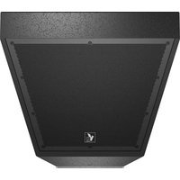
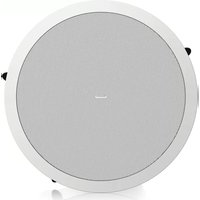
| Produkttyp | Inbyggnadshögtalare för tak |
| Märke | Tannoy |
| Modell | CMS 803 |
| Kategori | Högtalare |
| Högtalardiameter | 8 tum (203 mm) |
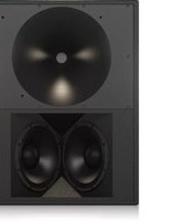
| Transduktortyp | Koaxial |
| Märkeffekt (RMS) | 100 W |
| Märkeffekt (topp) | 200 W |
| Nominell impedans | 16 ohm (lågimpedansversion) |
| 100 V-linjeversion | Tillgänglig med transformator 60 W / 30 W / 15 W / 7,5 W |
| Frekvensomfång | 70 Hz - 20 kHz |
| Maximal ljudtrycksnivå | 115 dB SPL (topp) |
| Täckningsvinkel | 90° (konisk) |
| Mått (diameter x djup) | 310 x 180 mm |
| Nödvändig utskärning | 280 mm |
| Nettovikt | 3,2 kg |
| Chassimaterial | Stål |
| Skyddsgaller | Ingår, i metall |
| Strömförsörjning | Passiv (kräver extern förstärkare) |
| Anslutningar | Skruvplint (lågimpedansversion) / Molex (100 V-version) |
| Driftstemperatur | 0°C till 45°C |
| Underhåll och rengöring | Rengör med en torr, icke-slipande trasa |
| Säkerhet | Öppna inte enheten. Överlåt all reparation till kvalificerad personal |
| Reservdelar och reparerbarhet | Galler, kon, transformator finns hos tillverkaren |
| Garanti | Se villkoren på Music Tribes webbplats |
Vanliga frågor - CMS 803 TANNOY
Användarfrågor om CMS 803 TANNOY
0 fråga om denna apparat. Svara på dem du kan eller ställ din egen.
Ställ en ny fråga om denna apparat
Ladda ner instruktionerna för din Högtalare i PDF-format gratis! Hitta din manual CMS 803 - TANNOY och ta tillbaka ditt elektroniska enhet i hand. På denna sida publiceras alla dokument som behövs för att använda din enhet. CMS 803 av märket TANNOY.
BRUKSANVISNING CMS 803 TANNOY
Vaming Uctag markorade med symbolen leder elektrisk stromstynka som är tilräckligt stark lin att utgåra en räk för eckrock. Använd endavt högvalitätiva, kommenselt tillgningliga högularkatlar med förhandsinstallerade N° 15-kontakter. All annan installering eller modifikation för endav utilises av kompetent personal.
Den här symbolen hänutsar till viktiga punkter om användning och underhåll i den medällande dokumentationen. Var winlig och läs bruiksonningen.
Försiktighet Mänka risken för elektriska stölar genom act airdig ta av biljet upptill på apparaten (eter ta av taksidan). Inti apparaten finns det inga delar som kan repareras av användaren. Undast kvalificerad personal för genomfiera repartitioner.
Försiktighet För att miniska risken för brand och elektriska störar ska apparaten stydås mot regn och fukt. Apparaten går inte utsättas för dropp eller spill och inga vattenbehälare som varer etc. får placeras på den.
Försiktighet Serviconstruktionen är embart assozdi för kwalifnerad serviconpersonal. Für att undvika risiken genom elektriska stütter, genomför inga reparationer på apparaten, vilka inte ar besikerna i huisvarworsungen. Endredi kwalifnerad laktoperational för genomliera reparationerna.
- Læ dessa anvåningar.
- Sparna dette anvåningar.
- Brøkka alle vøminger.
- Tåj alla anvåningar.
- Anvård på inte apparaten i förheten av varten.
- Bengår endst med som lora.
- Boderna inte ventilationspningjarna. Intalera enligt tivversarens anvåningar.
- Instalera idling attilom avmarkolor som väme element, varfaltsfandt, qvar eller annan utrusting som varger valmer (inklusive Bestandser).
-
Aroda idling en polarized eller opjord kontakt. En polarised kontakt har ett blad – det inte brechtsän det andra. Injord kontakt har ett blad och ett nøde jordsditt. Det brudet jaardet eller jordsditt är till för den sirkhet. Om den omföldande combatten into passar ett utlag, thus du konkreis en elektriken för att f ürttaget bytt.
-
Förligg elkabeln så, att det inte är möjligt att trampa på den och att den är skyddad mot skarpa kanter och inte kan skadas. Fösi synnecht akt på områdena omkring stickssontakterna, förlingningssablarna och på det ställe, där elkabeln lämmar apparaten, är bilräckligt skyddade.
-
Apparaten måste allid vara ansluten till einået med intakt skuddsledare.
-
Om huvudkontakten, eller EI apparatuttag, fungerar som avstänglingsenhet måste denna altod vara tilgånglig.
-
Använd endast tillkopplingar och tillbehör som angetis av tillverkaren.

eller som såts till- sammam med apparaten. Om du använder en vago, var fürsiktig, när du
förflyttar kombinationen vagn-apparat, för att förhindra öydsfall genom snubbling.
-
Dra uranslutningskontakten und förwider clernär asparaten inte ska användas under någon längre tid.
-
Låtkvalificeras personal utfra all service. Service är nödvändig när apparaten har skadats, t.ex. när en elkabel eller kontakt är skadat, vätska eller främmande föremål har kommt in i apparaten, eller när den har fällt i gelvet.
- Kassera produkten på rätt sitt: den här symbolen indikerar att produkten inte ska kastas i bushåtsopoms, enligt VILLIE direktet (2012/19/EU) och gällande, naturell lagsl tillning. Produkten ska förnes till ett produktserat återzinningsfälle för
ecistneomis och ecistne umstning (EEB). Om den här serens avall hantens på del seni kan miljän, och mässden häksä, plävea megulat, på grund av potentella utkautanser som offe assoeras med EBE. Arfaltanartons producten lämnet på attt stärar dera till att murenes resunder amniss på ett ban silte. Kontaste kommern, avsning forvalning eller arfaltbanatorenflotrag förer informer omation ermingsemral för produkten kan lämnere. Instalser inte telt trängt utyrem, etc. i en belkylka eller bhanide enhet. Plastera inte kälter med openen eld, tæn, dända lijas, på apparaten. Töning på miljanksterems vid konsering och batterer. Batterer mäse konsener på ett batterikuprandingstärle. Denna apparat sen användes tropiska och måligt skint up til 45 °C.
FRISKRIVNINGSKLAUSUL
Music Tribe tar inget anvar för någon förstutt som kan drabbas är någon person som helt eller debris föritar sig på någon beskrivning, fotograf och utalands som finns för. Tekniska skifikationer, utreenden och annar information kan Anders utan föregående meddelande. Alla varumärden tillor respektene agare. Midas. Clark Teknik, Lab Gruppen, Lake, Tanney, Turbosound, TC Electronic, TC Helicon, Behinger, Bugera, Falcon Microphones och Coolaudio är varumärden eller registrerade varumärden som tillhör Music Tribe Global Brands Ltd. Co Music Tribe Global Brands Ltd. 2022 Alla Rättigelter reservatode.
BEGRÄNSAD GARANTI
För tillämpiga garantiville och stetligare information om Music Tribes begränsade garanti, se fulständig information online på community.musictribe.com pages/supportinwarranty.

natural_image
Two 3D mechanical components with circular cavities and mounting holes, shown from different angles (no text or symbols visible)Accessories
Standard Accessories  Optional Accessories Installation Guide for Suspended Ceilings
1. Remove the ceiling tile from its frame and place it on a flat surface. Position the cutout template (self adhesive backed) on the tile. (Fig.1) 2. Cut out the hole in the ceiling tie using a pad saw following the broken line indicated on the template (Fig.2) 3. Place the C-Ring and tile-bridge on top of the ceiling panel, aligning the C-Ring over the hole, and screw the C-Ring to the tile bridge using the fixings provided. (Fig. 3) 4. Go to the 'Niring and Setting Up' chapter. 5. Slide the speaker assembly through the hole. Turn the screws (denoted "Screw Fix") clockwise on the front of the speaker to extend the mounting wings. Tighten the screws until a firm grip is achieved. (NOTE: Screws have a PoziDriv head; use of a PoziDriv driver is recommended). If using a power driver, set the speed setting to slow, Tammy recommends a torque setting of 1.5 km (recommended) and 2.6 km (maximum). (Fig. 4) DO NOT OVERTIGHTEN! 6. Attach the nylon safety to the hooks on the front taffle before attaching the gille by presenting it to the speakers and allowing the magnets to pull it into position (Fig.5). (With the CMS 403DCelCTe, the gille is already fitted to the product.) Quick Star Guide 15 EN NOTE ON INSTALLATION OF CMS 403DCe/ICTe:
Before tightening the screws in step 5, swivel the speaker in the desired direction. When the screws are tightened, the speaker will lock into position. Replace the front trim to conceal the mounting screws.Installation Guide for Sheetrock (Plasterboard) Ceilings
1. Position the cutout template (self adhesive backed) on the ceiling. (Fig.1) 2. Cut out the hole in the ceiling using a pad saw following the broken line indicated on the template then slide the C-ring into the ceiling, aligning it over the cut-out hole. (Fig.2) 3. Go to the 'Wiring and Setting Up' chapter, then return to point 4 below. 4. Slide the speaker assembly through the hole. Turn the screws (denoted "Screw Fix") clockwise on the front of the speaker to extend the mounting wings. Tighten the screws until a firm grip is achieved. (NOTE: Screws have a PocketDrive head; use of a PocketDrive driver is recommended). If using a power driver, set the speed setting to slow, Tannoy recommends a torque setting of 1.5 Nm (recommended) and 2.6 Nm (maximum). (Fig.3) DO NOT OVERTIGHTEN! 5. Attach the nylon safety to the hooks on the front table before attaching the grille by presenting it to the speakers and allowing the magnets to pull it into position (Fig.4). (With the CMS-403DCe/ICTe, the grille is already fitted to the product.)NOTE ON INSTALLATION OF CMS 403DCe/ICTe:
Before tightening the screws in step-1, stivel the speaker in the desired direction. When the screws are tightened, the speaker will lock into position. Replace the front trim to conceal the mounting screws.  Fig.1  [5]  | q.1  184Installation Guide for Optional Plaster Ring
Quick Star Guide An optional plaster (mud) ring bracket is available from Tannoy. This bracket is designed to be pre-installed into newly constructed, non-suspended ceilings. 1. Nail or screw the plaster ring to the joints. (Fig. 1) 2. Lay the speaker wiring to where the speaker will be fitted and complete the plastering work on the ceiling. (Fig.2) 3. Go to the 'Wiring and Setting Up' chapter, then return to point 4 below. 4. Slide the speaker assembly through the hole. Turn the screws (denoted "Screw Fox") clockwise on the front of the speaker to extend the mounting wings. Tighten the screws until a firm grip is achieved. (Note: Screws have a Poziziv head; use of a Poziziv driver is recommended). If using a power driver, set the speed setting to slow, Tannoy recommends a torque setting of 1.5 km (recommended) and 2.6 Nm (maximum). [Fig.3]DO NOT OVERTIGHTEN!
5. Attach the nylon safety to the hooks on the front baffle before attaching the grille by presenting it to the speakers and allowing the magnets to pull it into position (Fig.4). With the CMS 4030Co/CTe, the grille is already fitted to the product.)  Hg  Fig.2  B(3  FLL4NOTE ON INSTALLATION OF CMS 403DCE/ICTe:
Before tightening the screws in step 4, swivel the speaker in the desired direction. When the screws are tightened, the speaker will lock into position. Replace the front trim to conceal the mounting screws. 18 CMS 3.0 Series Quick Star Guide 19 ENInstallation Guide for Optional Pre-Installation Backcan (PI Models Only)
An optional pre-install backcan is available for all pre-install (PI) models. The backcan is designed for pre-installation in newly constructed, non-suspended ceilings. NOTE: The CMS 603DC/CT and CMS B83DC models have the transformer pre-attached to the inside of the backcan; the CMS 503DC/CT models have the transformer pre-attached to the loudspeaker assembly. 1. Attach the backcan to a safe and secure fixing point. This can be done in a number of ways. METHOD 1: Fix the backcan to a secure fixing point by using suitable fixings with the 4 fixing holes provided on the PI backcan. (Fig.1) METHOD 2: Secure the backcan to a safe and secure fixing point using suitable fixings with the flexible straps that are attached to the P1 backcan. (Fig.2) METHOD 3: a. Attach the PI backcan to the optional pre-mount ring (plaster ring) using the fixings provided with the pre-mount ring. (Fig.3) b. Next, secure the wings of the pre-mount ring to a safe and secure fixing point by using suitable fixings. (Fig.4) Please turn over  1  F42  131  F44Installation Guide for Optional Pre-Installation Backcan (PI Models Only)
2. Attach the conduit to the installed backcan. This can be done in two ways: METHOD 1: You can use the clamp at the back of the pre-install backcan. The product will accept a squeeze connector with a thread size of up to 22 mm. To remove the cable clamp, simply uncrew the threaded washer (under the wiring cover) which holds the cable clamp in place and replace it with a conduit squeeze connector. (Fig.5)  METHOD 2: You can use any of the three knock-out points at the sides of the PI backcan (19 mm, 22 mm or 28 mm diameter). (Fig.6)  3. If conduit is not chosen as the wiring method, run an approved speaker cable to the installed can. Terminate in the top mounted cable clamp or with an approved cable connector in one of the three knock-out points at the sides of the PI backcar. 4. Cut hole in the proper location in the ceiling using a pad saw. Place the pre-install backscan over the hole. (Fig.7)  5. Go to the 'Wiring and Setting Up' chapter, then return to point 6 below. 6. Side the speaker assembly through the hole. Turn the screws (denoted "Screw Fix") clockwise on the front of the speaker to extend the mounting wings. Tighten the screws until a firm grip is activated. (NOTE: Screws have a PostOrb head; use of a PostOrb driver is recommended). If using a power driver, set the speed setting to slow, Tammy recommends a torque setting of 1.5 Nm (recommended), and 2.6 Nm (maximum). (Fig. 8) DO NOT OVERTIGHTEN! 1. Attach the nylon safety to the hooks on the front baffle before attaching the grille by presenting it to the speakers and allowing the magnets to pull it into position. (Fig.9)   18月 Fig.5Wiring and Setting Up
1. Open the wiring cover (if applicable) and locate the Euro-type connector plug and socket at the back of the speaker. [Fig.1] 2. For connection to an amplifier, use Pins 1 and 2 (Fig.2); • Fin 1 is positive \- Pin 2 is negative For connection to additional speakers in a distributed line, Pins 3 and 4 are in parallel where: \- Pin 3 is negative \- Pin 4 is positive 3. Close the wiring cover and tighten both screws on the cable clamp (if applicable). 4. Use the rotary switch on the front of the unit to select low impedance (LoZ) mode or high impedance (70 V or 100 V) for distributed applications. THE SPEAKER IS SUPPLIED IN LOW IMPEDANCE MODE. NEVER CONNECT THE SPEAKER TO A 70/100 VOLT AMPLIFIER WHILE IT IS SET FOR LOW IMPEDANCE. CMS 403DC/e/ICTe and CMS 503DC/ICT models (all variants) use a 30W transformer. In distributed line applications, the transformer can be tapped at 30W , 15W and 7.5W , with an additional 3.75W tap for 70V line systems. [Fig.3] CMS 603DC/CT and CMS 803DC models (all variants) use a 60 W transformer. In distributed line applications, the transformer can be tapped at 60 W, 30 W and 15 W, with an additional 7.5 W tap for 70 V line systems. (Fig.4) Quick Star Guide 21  Fig.1  140.7  [1]  Fig.1Painting
If desired, the grille and baffle panel may be painted to match the surrounding décor. Painting the baffle: \- Carefully mask off the driver assembly using the paint mask provided to ensure that the paint does not come into contact with the cone and roll surround. \- Apply several thin coats of paint – this will provide a better finish than one overly thick coat. Painting the grille: - Carefully remove the acoustically transparent grille cloth from the reverse side of the grille. - Paint the grille and then replace the grille cloth - several thin coats of paint will provide a better finish than one overly thick coat. - Re-bond the grille cloth to the grille over the entire area using a light spray-adhesive to avoid audible resonances.Introducción
Gradas por comprar este producto de sistema de monitor de techo Tannoy. Diseñada para material de programas de voz y música, la gama Tannoy CMS proporciona una calidad de sonido excepcional y una fiabilidad a largo plazo en todas las aplicaciones de montaje en el techo. La serie CMS 3.0 DC presenta nuevos controladores concéntricos duales de 16 ohmios para un rendimiento mejorado y una vida útil prolongada.Desembalaje
Cada producto Tannoy se inspecciona cuidadosamente antes del envío. Después de desembalario, inspeccione su producto para asegurarse de que no se hayan producido daños durante el transporte. En el Improbable caso de daños, notifique a su distribuidor y conserve todos los materiales de envío, ya que su distribuidor puede requenir el envío de devolución. Todos los altavoces CNS se envían en pares y se suministran con los siguientes accesorios de serie: anillo en C, kit de puente de baldosas, plantilla recortada y máscara de pintura. Un anillo de yeso (barro) está disponible como accesorio opcional.Avisos de seguridad
Algunos códigos de construcción regionales requieren el uso de un método secundaria para asegurar los altavores en el techo para brindar la seguridad de un soporte de respuesta. Se debe conectar una línea de soporte secundaria desde el lazo de seguridad en la parte posterior del producto hasta un punto de origen en el techo. Para los modelos PL, la línea de soporte secundaria debe conectarse desde la parte posterior del chassis del controlador a un punto de origen en el techo. Consulte los códigos de construcción relevantes en su región. Al utilizar un controlador de potencia para instalar el producto, es esencial utilizar los ajustes de nivel de torsión correctos para evitar apretar demasiado y dañar el material del techo o las abrazaderas. Ajuste de par recomendado: 1,5 Nm Tannoy no se hace responsable de los daños causados por la instalación incorrecta de estos altavoces. El CMS 603 ICT LS es UL-1480, categoría UUMW, para uso con sistemas supervisados sin CC. Aviso de seguridad eléctrica: Para cumplir con la norma UL-1480, se requiere un conducto flexible revestido de metal (30) para la conexión al bloque de terminales para una conexión a tierra adecuada. Para cumplir con las regulaciones de UL, el backcan PI siempre debe usarse con los modelos CMS PI. 107. 托公头额N3 Hue en la de la de la de la de la de la de la de la de la de la de la de la de la de la de la de la de la de la de la de la de la de la de la de la de la de la de la de la de la de la de la de la de la de la de la de la de la de la de la de la de la de la de la de la de la de la de la de la de la de la de la 24 CMS 3.0 Series Quick Start Guide 25Identificación de características del producto
NOTA IMPORTANTE: Los dibujos de cada altavoz a continuación son genéricos y se aplican a los tipos de altavoces especificados. Algunas variaciones serán evidentes en algunos modelos, pero las diferencias no son críticas para fines de instalación, excepto cuando se indique lo contrario. Montaje ciego  Los modelos de montaje ciego se suministran con un backcan preinstalado. Lo anterior se aplica a todos los modelos, así como a cualquier otro que NO tenga el sufijo "PI". Preinstalar   Se muestra una unidad de preinstalación (Pf) sin el backan de preinstalación opcional. Preinstalación de backcan   Backcan opcional de preinstalación (PI) para modelos PI. ROTA: Los modelos CMS 603DC / ICT PI y CMS 803DC tienen el transformador preinstalado en el interior del backtan. El CMS 503DC / ICT PI tiene el transformador premontado al conjunto del altavoz.Accesorios
Accesorios Estandar    Accesorios Opcionales   Guía de instalación para falsos techos
1. Retire la loseta del techo de su marco y coliquela sobre una superficie plana. Coloque la plantilla de recorte (con respaldo autoadhesive) sobre la loseta. (Figura 1) 2. Corte el orificio en la loseta del techo con una sierra circular siguiendo la línea discontinua indicada en la plantilla (Fig. 2) 3. Coloque el anillo en C y el puente de azulejos en la parte superior del panel del techo, alineando el anillo en C sobre el crifido y atornille el anillo en C al puente de azulejos con las fijaciones proporcionadas. (Fig. 3) 4. “Vaya al capítulo ‘Cableado y configurador’”. 5. Deslice el conjunto de alcanzar a través del artículo. Gore los tornillos indicados como "Fijación por tornillo". El sentido de las aguajes al rejoj en la parte frontal del alcanzar para estender las atas montaje. Aparte los tornillos hasta lograr un agarre firme. ¡NOTA: Los tornillos tienen una cabeza FoxOliv; se recomienda el uso de un destornillador PostDevl). Sinus un controlador de potencia, establecara la configuración de velocidad en lenta. Tennyy recomienda una configuración de torque de 1,5 Km (recomendado) y 2,6 Km (maximum). Figura 4. ¡NO APRIETE DEMASIADO! 6. Coloque el segundo de nallon en los qanchos del deflector frontal antes de colocar la rejilla presentando la a los altavoces y permitendo que los imanes la coloquen en su posición (Fig.5). (Con el CKTS 4030Ce / ICTe, la rejilla ya está instalada en el producto).  1  18J  Fig3  14  1kgGuía de instalación para plafones de yeso (placas de yeso)
1. Coloque la plantilla de recorte (con respaldo autoadhesivo) en el techo. (Figura 1) 2. Corte el agujero en el techo con una sierra de almacadilla siguiendo la línea discontinua indicada en la plantilla y luego desice el anillo en C en el techo, almeindolo sobre el agujero recortado. (Figura 2) 3. Vaya al capítulo 'Cableando y configuración', luego vuelva al punto 4 a continuación. 4. Devise el conjunto de altanza a través del inficio. Gire los tomilles (indicados como "Jujación per terrilla") en el sentido de las agujos del reijez en la parte frontal del altanza para estender las alas de montaje. Apriete los tomilles hasta lograr un agaré firme. (101A. Los tomilles tienen una cabera Portillo; se recomienda el uso de un destomillador Poz.Dria). Siuso un controlador de potencia, estaleceza la configuración de velocidad en lenta. Tammy recomendada una configuración de torque de 1,5 Km (recomendado y 2,6 Km (máximo); Fig. 3) ¡NO APRIETE DEMASIADO! 5. Coloque el seguro de ralón en los ganchos del deflector frontal antes de colocar la rejilla presentándola a los altavoces y permitiendo que los imanes la coloquen en su posición (Fig. 4). (Con el CMS-403DCe / ICTe, la rejilla ya esta instalada en el producto).  Fig.1  图2  16p.  Fig.3 NOTA SOBRE LA INSTALACIÓN DE CMS 403 DCE / ICTe: Antes de apretar los tomillos en el paso 4, gire el altavoz en la dirección deseada. Cuando se apretar los tomillos, el artavoz se bloqueará en su posición. Reemplace la moldura frontal para ocultar los tomillos de montaje.NOTA SOBRE LA INSTALACIÓN DE CMS 403DCE / ICTe:
Antes de apretar los tornillos en el paso 5, gire el altavoz en la dirección deseada. Cuando se aprietan los tornillos, el altavoz se bloqueará en su posición. Reemplace la moldura frontal para ocultar los tornillos de montaje. 28 CMS 3.0 Series Quick Star Guide 29Guía de instalación para anillo de yeso opcional
Un soporte de anillo de yeso (barro) opcional está disponible en Tannoy. Este soporte está diseñado para ser preinstalado en techos no suspendidos de nueva construcción. 1. Cave o atornille el anillo de yeso a las vigas. (Figura 1)  Fig.1 2. Coloque el cablicado del altavoz en el lugar donde se instalará el altavoz y complete el trabajo de enlucido en el techo. (Figura 2) 3. Vaya al capítulo 'Cabrado y configuración', luego vuelva al punto 4 a continuación.  182 4. Deslice el conjunto de altarzo a través del oficio. Giro los tornillos indicados como "Fijación por tornillo" en el sesión de las agujas del relay en la parte frontal del altavazo para estender las atos de montaje. Apudite los tornillos hasta lograr un agarre firme. (Notar, los tornillos tienen una cabeza Pezilnoy; se recomienda el uso de un destornillador Pezilnoy). Suisa un controlador de potencia, establezla la configuración de velocidad en lanta. Tammy recomienda una configuración de bloque de 1,5 Km (recomendado) y 2,6 Km (múximol, Fig. 3). ¡NO APRIETE DEMASIADO!  图1 5. Coloque el seguro de nación en los ganchos del deflector frontal antes de colocar la rejilla presentándola a los altavoces y permitiendo que los imanes la coloquen en su posición (Fig.4). ¡Con el CMS 403DGe / ICle, la rejilla ya está instalada en el producto).  图4NOTA SOBRE LA INSTALACIÓN DE CMS 403DCe / ICTe;
Antes de aprielar los tornillos en el paso 4, gire el altavoz en la dirección deseada. Cuando se aprielar los tornillos, el altavoz se bloqueará en su posición. Recemplace la motura frontal para ocultar los tornillos de montaje.Guía de instalación para Backcan de preinstalación opcional (solo modelos PI)
Un backran opcional de preinstalación está disponible para todos los modelos de preinstalación (P). El backan está diseñada para la preinstalación en techos no suspendidos de nueva construcción. NOTA: Los modelos CMS 603DC / ICT y CMS 803DC tienen el transformador preinstalado en el interior del backcan; los modelos CMS 503DC / ICT tienen el transformador premontado al conjunto de altavoz. 1. Fije la lata posterior a un punto de fijación seguro y protegido. Esto se puede hacer de varias formas. MÉTODO 1: Fije el backsan a un punto de fijación seguro utilizando fijaciones adecuadas con los 4 orificios de fijación provstos en el backsan PL. (Figura 1)  e.1 MÉTODO 2: Asegúre el backcan a un punto de fijadón seguro y seguro usando fijaciones aceptradas con las corteas flexibles que están unitas al backcan Pl. (Figura 2)  [Unreadable]MÉTODO 3
a. Conerte la lata posterior Pl al anillo de premontaje opcional (anillo de yeso) utilizando las fijaciones proporcionadas con el anillo de premontaje. (Fig. 3)  Fig.2 b. A continuación, asegure las alas del anillo de premontaje a un punto de fijación seguro mediante el uso de fijaciones adecuadas. (Figura 4)  1kgA Por favor dese la vueltaGuía de instalación para Backcan de preinstalación opcional (solo modelos PI)
2. Conecte el conducto a la bandeja trasera instalada. Esto se puede hacer de dos maneras: MÉTODO 1: Puede utilizar la abrazadera en la parte posterior del backcan preinstalado. El producto aceptará un conector de compresión con un tamaño de rosca de hasta 22 mm; para quitar la abrazadera del cable, simplamente desatornille la arandela roscada (debajo de la cubierta del cableado) que sujeta la abrazadera del cable en su lugar y reemplácela con un conector de compresión de conducto. (Figura 5)  MÉTODO 2: Puede utilizar cualquiera de los tres puntos ciegos a los lados del backcan PI (19 mm, 22 mm o 28 mm de diámetro). (Figura 6)  3. Si no se elige un conducto como método de cableado, coloque un cable de altavoz aprobado en la lata instalada. Termine en la abrazadora de cable montada en la parte superior o con un conector de cable aprobado en uno de los tres puntos ciegos a los lados del backan PL. 4. Haga un agujero en la ubicación adecuada en el techo con una sierra de almohadilla. Coloque la lata trascra preinstalada sobre el orificio. (Figura 7)  5. Vaya al capítulo 'Cableado y configuración', luego vuelva al punto 6 a continuación. 6. Deslice el conjunto de altava a través del análisis. Gire los tomillos (indicados como "Fijación por torilla") en el sentido de las agujas del reisí en la parte frontal del altove para extender las áto de montaje. Apriete los tomillos hasta lograr un agarre firme. ("NIA). Los tomillos tienen una cabeza Postiliza; se recomienda el uso de un destomilador Pazoliva). Susa un controlador de potencia, establezta la configuración de velocidad en lenta. Tarnoy recomienda una configuración de torque de 1,5 Km (recomendido) y 2,6 Km (máximo). (Figura 8) ¡NO APRIETE DEMASIADO! 7. Coloque el seguro de nailon en los ganchos del deflector frontal antes de colocar la rejilla presentándola a los altavoces y permitiendo que los imanes la coloquen en su posición. (Figura 9)  Cableado y configuración
1. Abra la tapa del cableado (si corresponde) y ubique el enchufe y el enchufe del conector tipo europeo en la parte posterior del altavoz. (Figura 1) 2. Para la conexión a un amplificador, use los pines 1 y 2 (Fig.2): • ß pin 1 es positivo \- B pin 2 es negativo Para la conexión a altavoces adicionales en una línea distribuida, los pines 3 y 4 están en paralelo donde: \- El pin 3 es negativo • El pin 4 es positivo 1. Cierre la cubierta del cableado y aplete ambos tomillos en la abrazadera del cable (si corresponde). 4. Use el interruptor giratorio en la parte frontal de la unidad para seleccionar el modo de baja impedancia (LoZ) o alta impedancia (70 V o 100 V) para aplicaciones distribuidas. EL ALTAVOZ SE SUMINISTRA EN MODO DE BAJA IMPEDANCIA. NUNCA CONECTE EL ALTAVOZ A UN AMPLIFICADOR DE 70/100 VOLTIOS MIENTRAS ESTÉ CONFIGURADO PARA BAJA IMPEDANCIA. Los modelos CMS 403DCe /ICTe y CMS 503DC /ICT (todas las variantes) utilizan un transformador de 30 W. En aplicaciones de línea distribuida, el transformador se puede conectar a 30 W, 15 W y 7,5 W, con una derivación adicional de 3,75 W para sistemas de línea de 70 V. (Fig. 3) Los modelos CMS 603DC / ICT y CMS 803DC (todas las variantes) utilizan un transformador de 60 W. En aplicaciones de línea distribuida, el transformador puede conectarse a 60 W, 30 W y 15 W, con una derivación adicional de 7,5 W para sistemas de línea de 70 V. (Figure 4)  F4  192  Fig.1  Fig.1Cuadro
Si lo desea, la rejilla y el panel deflector se pueden pintar para que combinen con la decoración circundante. Pintar el deflector: - Enmascare con cuidado el conjunto del impulsor usando la miscara de pintura provista para asegurarse de que la pintura no entre en contacto con el como y el bonde del rodillo. - Aplique varias capas delgadas de pintura; esto proporcionará un mejor acabado que una capa demasiado gruesa. Pintar la reilla: - Retire con cuidado la tela de reilla acústicamente transparente del reverso de la rejilla. - Pinte la rejilla y luego vuelva a colocar la tela de la rejilla; varias capas finas de pintura proporcionarán un mejor acabado que una capa demasiado gruesa. - Vuelva a adherir la tela de la rejilla a la rejilla en toda el área con un adhesivo en aerosol ligero para evitar resonantas audibles.Introduction
Merci d'amir achetée ce produit Tannoy Ceiling Monitor Systems. Conque pour les programmes voraux et musicaux, la gamme Tannoy CNS offre une qualité sonore exceptionnelle et une fiabilité à long terme dans toutes les applications de montage au plafond. La série CNS 3.0 DC comprend de nouveaux pilotes 76 ohms Dual Concentrice pour des performances améliorées et une durée de vie prolongée.Déballage
Chaque produit Tannoy est seigneusement inspecté avant expédition. Après le déballage, veuillez inspecter votre produit pour vous assurer qu'aucun dommage n'est surveu pendant le transport. Dans le cas improbable de dommages, veuillez en informer votre revendeur et conserver tout le matériel d'expédition car votre revendeur peut edger un retour. Toutes les enceintes CMS sont expédiées par paires et sont fournies avec les accessoires suivants en standard: anneau en C, kit de pont de tuiles, gabarit de découpe et masque de peinture. Un anneau de plâtre (boue) est disponible en option.Avis de Sécurité
Certain codes de construction régionale exigent l'utilisation d'une méthode secondaire de fixation des haut-parleurs au plafond pour assurer la sécurité d'un support de secours. Une ligne de support secondaire dont être fixée entre la bourse de sécurité à l'arrière du produit et un point source au plafond. Pour les modèles PI, la ligne de support secondaire dont être fixée de l'arrière du chassis du pilote à un point source au plafond. Veuillez consulter les codes de construction pertinents dans votre région. Lorsque vous utilisez un pilote d'alimentation pour installer le produit, il est essentiel d'utiliser les réglages de niveau de couple corrects pour éviter un serrage excessil et des dommages au matériau du plafond ou aux places. Couple de serrage recommandé: 1,5 km Tannoy ne sera pas tenu responsable des dommages causes par une mauvaise installation de ces enceintes. Le CMS 603 ICT LS est UL-1480, catégorie UUMW, pour une utilisation avec des systèmes supervisés non DC. Arts de sécurité électrique. Pour se conformer à la norme UI-1480, un conduit flexible gaine de métal (BX) est nécessaire pour la connexion au bonnier pour une mise à la terre correcte. Afin de se conformer aux réglementations UL, le backcan PI doit toujours être utilisé avec les modèles CMS PI. NOTE DE SECURITÉ In the case of the case, we have been a large number of cases that are 100% of the case is made in the case, but there is no effect on the case. We have been a large number of cases that are 100% of the case is made in the case, but there is no effect on the case.Identification des caractéristiques du produit
REMARQUE IMPORTANTE: Les schémas de chaque enceinte ci-dessous sont génériques et s'appliquent aux types d'enceintes spécifiés. Certaines variations seront apparentes dans certains modèles, mais les différences ne sont pas critiques à des fins d'installation, sauf indication contraire. Monture aveugle  Les modèles à montage en accuegie sont fournis avec un backcam pré installé. G-dessus s'applique à tous les modèles ainsi qu'à tous les autres qui n'ont PAS de suffine «Pla Pré-installer   Une unité de pré-installation (PI) est illustrée sans le backran de pré-installation en option. Pré-installer le backcan   Backcan de pré-installation (PI) en option pour les modèles PI. REVARQUE: Les modèles CVS 603DC / ICT PI et CNS 803DC ont le transformateur pré-attaché à l'intérieur du backan. Le CVS 503DC / ICT PI a le transformateur pré-attaché à l'ensemble d'ençintes. CMS 3.0 SeriesAccessoires
Accessoires Standards  Accessoires Optionnels Guide d'installation pour les plafonds suspendus
1. Retirez la dalle de plafond de son cadre et placez-la sur une surface plane. Positionnez le gabant de découpe (dos auto adnésil) sur le carreau. (Fig. 1) 2. Descoupez le trou dans la date de plafond à l'aide d'une scie circulaire en suivant la ligne brisée indiquée sur le gabarr (Fig.2) 3. Placez l'anneau en C et le pont de carneaux sur le dessus du panneau de plafond, en alignant l'anneau en C sur le trou, et vissez l'anneau en C au pont de carneaux à l'aide des fixations fournies. (Fig.3) 4. Allez au chapitre «Câblage et configuration» 5. Fartes utiliser l'assentritage du haut-gardeur à travers le trou. Toumez les vis (notées «Secret Floix » dans le sens des signalles d'une montre à l'avent de l'encontre pour étendre les ailles de montage. Sorrez les vis jusqu'à ce qu'une prise ferme soit obtenue (REMARQUE) les vis ont une tête PazDinix, l'utilisation d'un tournevis PazDiniv est recommandée). Si vous utilisez un pilote électrique, règle la victisse sur lente, Tammy recommande un réglage de couple de 3,5 Km (recommandé) et 2,6 Km (maufmann). (Fig. 4) NE PAS TROP SERRER! 6. Attachez la sécurité en myon aux crochets du déflecteur avant avant de fixer la grille en la présentant aux haut parleurs et en laissant les aimants la tirer en position (Fig.5). (Avec le CMS 403BCe / ICTe, la grille est déjà montée sur le produit.)REMARQUE SUR L'INSTALLATION DE CMS 403DCe / ICTe:
Avant de semer les vis à l'étape 5, faites pivoter l'enceinte dans la direction souhaitée. Lorsque les vis sont serrées, le haut-parleur se verrouille en position. Remettez la garniture avant pour dissimuler les vis de montage. Quick Star Guide 37  Hg! FR  log?  Fig.3  18.4  Fig.2 38 CMS 3.0 Series Quick Star Guide 39Guide d'installation des plafonds Sheetrock (plaques de plâtre)
1. Positionnez le gabarit de découpe (dos autocollant) sur le plafond. (Fig. 1) 2. Déconpez le trou dans le plafond à l'aide d'une scie circulaire en suivant la ligne trésée indiquée sur le gabarit, puis faites glisser l'anneau en C dans le plafond, en l'alignant sur le trou découpé. (Fig.2) 3. Allez au chapitre «Câblage et configuration», puis revenez au point 4 ci dessous. 4. Faites glèster l'assemblage du haut, parleur à travers le tour. Trounce les vis (+)ées « Screw fixé » dans le sens des équilles d'une montre à l'avant de l'enolitaire pour étendre les elles de montage. Serne les vis jusqu'à ce qu'une prise ferme soit obtenue. JHEAQUARE : les vis ont une tête Position, l'utilisation d'un tournaments Position est recommandée. Si vous utilisez un pilote électrique, réglez la vitesse sur latte, Tannoy recommande un réglage de couple de 1,5 Km (recommandé) et 2,6 Km (maximum). (Fig. 3) NE PAS TROP SERRER! 5. Attachez la sécurité en nylon aux crochets du déflecteur avant avant de fixer la grille en la présentant aux haut-partours et en laissant les aimants la mettre en place (Fig.4). (Avec le CMS 403DCe / KTe, la grille est déjà montées sur le produit.)REMARQUE SUR L'INSTALLATION DE CMS 403DCe / ICTe:
Avant de serrer les vis à l'étape 4, faites pivoter l'encinte dans la direction souhaitée. Lorsque les vis sont serrées, le haut-parleur se verrouille en position. Remettez la garniture avant pour dissimuler les vis de montage.  Fig.1  [5]  | q.1  184Guide d'installation de l'anneau de plâtre en option
Un support d'anneau en plâtre (boue) en option est disponible auprès de Tannoy. Ce support est conçu pour être pré-installé dans des plafonds non suspendus nouvellement construits. 1. Clouez ou vissez l'anneau de plâtre aux solves. (Fig. 1) 2. Poses le câblage du haut parleur à l'endroit ou le haut, parleur sera installé et terminez les travaux de plâtrage au plafond. (Fig.2) 3. Allez au chapitre «Câblage et configuration», puis revenez au point 4 ci-dessous. 4. Faites glisser l'assemblage du haut parleur à travers le trou, Tourmez les vis (notées «Screw Floix») dans le sens des alguites d'une montre à l'avant de l'encente pour étendre les altés de montage. Serrez vis vis jusqu'à ce qu'une prise ferme soit obtenue. (Remarque: les vis ont une tête PoziDriv, l'utilisation d'un tournez PoziDriv est recommandée). Si vous utilisez un pilote électrique, réglez la vitesse sur lente. Tauney recommande un réglage de couple de 1,5 km (récommande) et 2,6 km (maximum). (Fig. 3) NE PAS TROP SERRERI 5. Attacher la sécurité en nylon aux crochets du déflecteur avant avant de fixer la grille en la présentant aux haut-parleurs et en laissant les aimants la mettre en place (Fig.4). (Avec le CMS 403Dc / ICTe, la grille est déjà montée sur le produit.)  Fig.1  H27  Fig.3  Fig.1REMARQUE SUR L'INSTALLATION DE CMS 4030Ce / ICTe:
Avant de serrer les vis à l'étape 4, faites pivoter l'enceinte dans la direction souhaitée. Lorsque les vis sont serrées, le haut-parleur se verrouille en position. Nemettez la garniture avant pour dissimuler les vis de montage.Guide d'installation pour l'analyse rétrospective de pré-installation en option (modèles PI uniquement)
In backcan de pré-installation en option est disponible pour tous les modèles de pré-installation (P). Le backcan est conçu pour la pré-installation dans des plafonds non suspendus nouvellement construits. REMARQUE: Les modèles CMS 603DC / ICT et CMS 803DC ont le transformateur pré attaché à l'intérieur du backran; les modèles CMS 503DC / ICT ont le transformateur pré attaché à l'ensemble de haut-parleurs. 1. Threz le backran à un point de formation sur et sécurisé. Cela peut être fait de plusieurs manières. MÉTHODE 1: Fixez le backcan à un point de fixation sécurisé en utilisant des fixations appropriées avec les 4 trous de fixation foumis sur le backcan PL. (Fig. 1)  Fig. 1 MÉTHODE 2: Fixez le hackcan à un point de fixation sur et sécurise à l'arte de fixations appropriées avec les sangles flexibles qui sont attachées au hackcan PL. (Fig.2)  132MÉTHODE 3:
une. Fixez le backran Pl à la baque de pré-montage en option (baque en plâtre), à l'aide des férations fournies avec la baque de pré-montage. [Fig.3]  F43 b. Ensuite, fixez les ailes de la bague de pré-montage à un point de fixation sûr et sécurisé en utilisant des fixations appropriées. (Fig.4)  131 Veuillez retournerGuide d'installation pour l'analyse rétrospective de pré-installation en option (modèles PI uniquement)
2. Flez le conduit au backran installé. Céci peut être fait de deux façons: MÉTHODE 1: Vous pouvez utiliser la pince à l'année du backzan de pré-installation. Le produit accepte un connecteur à compression avec une taille de filetage allant jusqu'à 22 mm. Pour retirer le sere-câble, dévissez simplement la rondelle filetée (sous le couvercle du câblage) qui maintient le sere-câble en place et remplierez le par un connecteur à pression pour conduit. (Fig. 5)  Condu Comdu. Equinere Connect MÉTHODE 2: Vous pouvez utiliser l'un des trois points d'éjection sur les côtes du backcan PI (diamètre 19 mm, 22 mm ou 28 mm). (Fig.6)  13.6 3. Si le conduit n'est pas choisi comme méthode de câblage, scheminez un cable d'encinte approuvé vers la boîte installée. Términez dans le serre-câble monté sur le dessus ou avec un connecteur de cable approuvé dans l'un des trois points de défonçage sur les cités du backcan PI. 4. Découpez le trou au bon endroit dans le plafond à l'aide d'une scie circulaire. Placez le backran de pré-installation sur le trou. (Fig.7)  [Unreadable] 5. Allez au chapitre «Câblage et configuration», puis revenez au point 6 ci-dessous. 6. Faites glisser l'assemblage du haut, pour sur à travers le trou. Tournez les vis (ménées «Screw Fixo) dans les sons des algilles d'une montre à l'avant de l'exercice pour étendre les alles de montage. Serrrez les abus qu'à ce qu'une prise ferme soit obtenue. JEANHAQUE les vis ont une tête Position, l'utilisation d'un tournerets Position est recommandés. Si vous utiliser un pilote électrique, régiez la vitesse sur lente. Tannoy recommande un réglage de couple de 1,5 Km (recommundié) et 2,6 Km (maximum). (Fig. 8) NE PAS TROP SERRER! 7. Attachez la sécurité en nylon aux crochets du déflecteur avant avant de fixer la grille en la présentant aux haut-pardeurs et en laissant les aimants la mettre en place. (Fig.9)  增  Fig.5Câblage et configuration
1. Ouren le couvercie du cablage (le cas échéant) et localisez la fiche et la prise du connecteur de type européen à l'arrière de l'enceinte. (Fig. 1) 2. Pour la connexion à un amplificateur, utilisez les broches 1 et 2 (Fig.2): • La broche l est positive • La broche 2 est négative Pour la connexion à des haut-parleurs supplémentaires dans une ligne distribuée, les broches 3 et 4 sont en parallele où: • La broche 3 est négative • La broche 4 est positive l'ennez le couverde du cablage et serrez les deux vis sur le serre-cable (le cas échéant). Utilisez le commutateur rotatif à l'avant de l'unité pour sélectionner le mode basse impédance (LoZ) ou haute impédance (70 V ou 100 V), pour les applications distribuées. LE HAUT-PARLEUR EST FOURNI EN MODE BASSE IMPÉDANCE. NE JAMAIS CONNECTER L'ENCEINTE À UN AMPLIFICATEUR 70/100 VOLT PENDANT QU'IL EST RÉGLÉ SUR UNE FAIBLE IMPÉDANCE. Les modèles CMS 403DCe / ICTe et CMS 503DC / ICT (boutes les variantes) utilisent un transformateur de 30 W. Dans les applications de ligne distribuée, le transformateur peut être alimente à 30 W, 15 W et 7,5 W, avec une prise supplémentaire de 3,75 W pour les systèmes de ligne 70 V. (Fig.3) Les modèles CMS 603DC / ICT et CNS 803DC (toutes les variantes) utilisent un transformateur de 60 V. Dans les applications de ligne distribuée, le transformateur peut être alimenté à 60 V, 30 V et 15 V, avec une prise supplémentaire de 7,5 V pour les systèmes de ligne 70 V. (Fig.4) Quick Star Guide 43  [Unreadable]  1027  (b).  Fig.1Peinture
Si vous le souhaitez, la grille et le panneau déflecteur peuvent être peints pour correspondre au décor environnant. Peindre le déflecteur: - Masquez soigneusement l'assemblage du pilote à l'aide du masque de peinture fourni pour vous assurer que la peinture n'entre pas en contact avec le cône et le contour du rouleau. - Appliquez plusieurs couches minces de peinture - cela fournira une meilleure finition qu'une couche trop épaisse. Peindre la grille: • Retirez soigneusement le tissu de la grille acoustiquement transparent de l'arrière de la grille. - Peignez la grille, puis remplacez le tissu de la grille - plusieurs fines couches de peinture fourniront une meilleure finition qu'une couche trop épaisse. - Recollez le tissu de la grille à la grille sur toute la zone à l'aide d'un léger spray adhésif pour éviter les résonances audibles.Einführung
Vielen Dank, dass Sie sich für dieses Produkt des Tannoy Ceiling Monitor System entschieden haben. Die Tannoy CMS-Reihe wurde sowohl für Sprach- als auch für Musikprogrammmaterial entwickelt und bietet außergewöhnliche Klangqualität und langfristige Zuverlässigkeit in allen Deckenmontageanwendungen. Die CMS 3.0 DC-Serie verfügt über neue 16-Ohm-Dual-Concentric-Treiber für verbesserte Leistung und längere Lebensdauer.Auspacken
Jodes Tannoy-Produkte wird vor dem Versand sorgfältig geprüft. Überprüfen Sie Ihr Produkt nach dem Auspacken, um sicherzustellen, dass während des Transports keine Schäden aufgetreten sind. Im unwahrscheinlichen Fall eines Schadens benachrichtigen Sie bitte ihren Händler und bewalnen Sie alle Versandmaterialien auf, da ihr Händler möglicherweise eine Rücksendung verlangt. Alle CMS-Lautsprecher werden paarweise geliefert und sind standardmäßig mit folgendem Zubehör ausgestattet: C-Ring, Fliesenbrückensatz, ausgeschnittene Schablone und Farbmaske. Optional ist ein Gipsring erhältlich.Sicherheitshinweise
Einige regionale Bauvorschriften erfordern die Verwendung einer sekundären Methode zum Befestigen von Lautsprechem in der Decke, um die Sicherheit einer Backup-Unterstützung zu gewährleisten. Eine sekundäre Stützleitung sollte von der Sicherheitschlaufe auf der Rückseite des Produkts an einem Quellpunkt an der Decke angebracht werden. Bei PI-Modellen sollte die sekundäre Stützleitung von der Rückseite des Treibergehäuses an einem Quellpunkt an der Decke angebracht werden. Bitte konsultieren Sie die entsprechenden Bauvorschriften in Ihrer Region. Wenn Sie ein Produkttreiber zur Installation des Produkts verwenden, müssen Sie unbedingt die richtigen Drehmomentstufeneinstellungen verwenden, um ein zu festes Anziehen und eine Beschädigung des Deckenmaterials oder der Klemmen zu vermeiden. Empfohlene Drehmomenteleinstellung: 1,5 Mm Tannoy haftet nicht für Schäden, die durch die unsachgemäße Installation dieser Lautsprecher verursacht werden. Der CMS 603 ICT LS ist UL-1480, Kategorie IIUWW, zur Verwendung mit nicht DC-überwachten Systemen. Elektrischer Sicherheitshinweis. Um der Norm UL-1480 zu entsprechen, ist für den Anschluss an den Klemmenblock eine metallbeschichtete flexible Leitung (BX) erforderlich, um eine ordnungsgemäße Erdung zu gewährleisten. Um den UL-Vorschriften zu entsprechen, muss der PI-Backran immer mit den CMS PI-Modellen verwendet werden. 30倍以上 In der bilanzielle, die beizule nicht man auf 30.500, 1998, zu beizule, die in der bilanzielle mit dem den U.S. Banken, aus dem Lienbaren lang, sich bei, mit dem U.S. Banken und Lienbaren lang, sich bei, mit dem U.S. Banken und Lienbaren lang, sich bei, mit dem U.S. Banken und Lienbaren lang, sich bei, mit dem U.S. Banken und Lienbaren lang, sich bei, mit dem U.S. Banken und Lienbaren lang, sich bei, mit dem U.S. Banken und Lienbaren lang, sich bei, mit dem U.S.Identifizierung der Produktmerkmale
WICHTIGER HINWEIS: Die Zeichnungen für jeden der folgenden Lautsprecher sind allgemein gehalten und gehen für die angegebenen Lautsprechertypen. Einige Abweichungen sind bei einigen Modellen erkennbar, aber Unterschiede sind für Installationswerte nicht kritisch, sofern nicht anders angegeben. Blind Mount natural_image
3D rendering of a cylindrical mechanical component with mounting holes and a small labeled component (no visible text or symbols)Zubehör
Standardzubehör   Optionales Zubehör Installationsanleitung für abgehängte Decken
1. Entfernen Sie die Deckerplatte von Ihrem Rahmen und legen Sie sie auf eine ebene Fläche. Positionieren Sie die Ausschnittschablione (selbstkiebundt auf der Fliese. [Abb. 1] 2. Schneiden Sie das Loch in der Deckenplatte mit einer Püstersäge aus und folgen Sie dabei der auf der Schablone angegebenen gestrichelten Linie (Pbb. 2). 1. Iegen Sie den C-Ring und die Fliesenbrücke auf die Deckenplatte, richten Sie der C-Ring über dem Loch aus und schrauben Sie den C-Ring mit den mitgelieferten Befestigungen an der Fliesenbrücke fest. (Abb. 3) 4. Fahren Sie mit dem Kapitel Verkabelung und Einrichtung' fort. 5. Schreiben Sie die Lautsprecherbangruppe durch das Lach. Drehen Sie die Schrauben (nott „Screw Die“ bezeichnet) an der Vorderseite des Lautsprechen im Unzigersmann, um die Montagelfgel zu verzengem. Ziehen Sie die Schrauben an, bis ein fester Griff erreicht ist. JHINWDS: Schrauben haben einen PostDriv-Kopf. Die Verwendung eines PostDriv-Trechen wird empfohlen. Wenn Sie einen Kraftschanter verwenden, stellen Sie die Geschwindigsteileinstellung auf langsam ein, Tannoy empfeielt eine Einstromentsleistung von 1,5 Km (empfohlen) und 2,6 Km (maximal). (Abb. 4)NICHT ÜBERDREHEN!
6. Befestigen Sie die Nylonsicherung an den Haken an der vorderen Schallwand, bevor Sie das Gitter anbringen, indem Sie es den Laubsprechem präsentieren und den Magneten erlauben, es in Position zu ziehen (Abb. 5). (Beim CMS 4010Ce JICTe ist der Kühlergrill bereits am Produkt angebracht.)  §1  18J  Fig.3  14  §3Installationsanleitung für Decken aus Sheetrock (Gipskartonplatten)
1. Positionieren Sie die Ausschnittschablone (selbstklebende Rückseite) an der Decke. [Abb.1] 2. Schneiden Sie das Loch in der Decke mit einer Polstersäge aus, indem Sie der auf der Schulzone angegebenen gestricheten Linie folgen. Schieben Sie dann den C-fing in die Decke und richten Sie ihn über dem ausgeschnittenen Loch aus. (Abb.2) 3. Gegen Sie zum Kapitel 'Verkabelung und Einrichtung' und kehren Sie dann zu Punkt 4 zurück. 4. Schreiben Sie die Laufsprecherbaugrupme durch das Loch, Drehen Sie die Schrauben (mit „Screen Fix“ bezeichnet; an der Vorderseite des Laufsprechers im Unzeigersinn, am die Montagefülliger zu verlangem. Ziehen Sie die Schrauben an, bis ein festor Griff richtigt ist. «HHWES: Schrauben haben einen PozDriv-KopL. Die Verwendung eines PozDriv-Treibers wird empfohlen.» Wenn Sie einen Kraftschrauber verwenden, stellen Sie die Geschwindigkeitsinstellung auf langsaum ein, Tannoy empfiehlt eine Odermomentenstellung von 1,5 Km (empfehlung) und 2,5 Km (maximalt). (Roh. 3)NICHT ÜBERDREHEN!
5. Befestigen Sie die Nylonsicherung an den Haken an der vorderen Schallwand, bewor Sie den Kühlengrill anbringen, indem Sie ihn den Laufsprechem präsentieren und den Magneten erlaufen, ihn in Position zu ziehen (Abb. 4), [Beim CMS 403DCE / I Le ist der Kühlengrill bereits am Produkt angebracht.]  Fig.1  Fig.2  16.  Fig.3HINWEIS ZUR INSTALLATION VON CMS 403Dc / ICTe:
Schwenken Sie den Lautsprecher in die gewünschte Richtung, bevor Sie die Schrauben in Schritt 4 festzichen. Wenn die Schrauben angezogen sind, rastet der Lautsprecher ein. Bringen Sie die vondere Verkleidung wieder an, um die Befestigungsschrauben zu verdecken.HINWEIS ZUR INSTALLATION VON CMS 403DCe / ICTe:
Schwenken Sie den Lautsprecher in die gewünschte Richtung, bevor Sie die Schrauben in Schritt 5 festziehen. Wenn die Schrauben angezogen sind, rastet der Lautsprecher ein. Bringen Sie die vordere Verkleidung wieder an, um die Befestigungsschrauben zu verdecken.Installationsanleitung für optionalen Gipsring
Eine optionale Gipsninghalterung ist bei Tannoy erhältlich. Diese Halterung kann in neu gebaute, nicht abgehängte Decken vorinstalliert werden. 1. Den Gipsring an die Balken nagein oder schrauben. [Abb.1] 2. Verlegen Sie die Lautsprecherkabel an der Stelle, an der der Lautsprecher angebracht werden soll, und schließen Sie die Verputzarbeiten an der Decke ab. (Abb.2) 3. Gehen Sie zum Kapitel "Verkabelung und Einrichtung und kehren Sie dann zu Punkt 4 zurück. 1. Verlegen Sie die Lautsprecherkabel an der Stelle, an der der Lautsprecher angebracht werden soll, und schließen Sie die Verputzarbeiten an der Decke ab. (Abb.2) 3. Gehen Sie zum Kapitel "Verkabelung und Einrichtung und kehren Sie dann zu Punkt 4 zurück. 4. Schieben Sie die Lautsprecherbaugruppe durch das Loch. Drehen Sie die Schrauben (mit „Screw Fix“ bezeichnet) an der Vorderseite des Lautsprechers im Uhrzeugersinn, um der Montagsstiftigten zu verfülligen, Ziehen Sie die Schrauben an, bis ein fester Griff bereinigt ist. (Einweis: Schrauben haben einen PazDriv-Kopf). Die Verwendung eines PazDriv-Treibers wird empfohlen.) (Wenn Sie einen Kraftschrauber verwenden, stellen Sie die Geschwindigkeitsinstellung auf langsam ein. Tannoy empfieht eine Drahmomentenstellung von 1,5 Km (empfohlen) und 2,6 Km (maximal). Vol. 3)NICHT ÜBEADREHEN!
5. Behestigen Sie die Nylorsicherung an den Haken an der wunderen Schaltwand, bevor Sie den Kühlergrill anbringen, indem Sie ihn den Lautsprechern präsentieren und den Magneten erlauben, ihn in Position zu kleinen (Abb. 4). (Beim CMS 403DCe / ICTe ist der Kühlergrill bereits am Produkt angebracht.)  +51  Fig.2  [1]  124HINWEIS ZUR INSTALLATION VON CMS 403DCe / ICTe:
Schwenken Sie den Lautsprecher in die gewünschte Richtung, bevor Sie die Schrauben in Schritt 4 festziehen. Wenn die Schrauben angezogen sind, rastet der Lautsprecher ein. Bringen Sie die vordere Verkeldung wieder an, um die Befestigungsschrauthen zu verdecken.Installationsanleitung für den optionalen Backcan vor der Installation (nur PI-Modelle)
Für alle PI-Modelle (Pre-Install) ist ein optionaler Backran vor der Installation verfügbar. Der Backran ist für die Vorinstallation in neu erichteten, nicht abgehängten Decken vorgesehen. HINWEIS: Bei den Modellen CMS 603DC / ICT und CMS 803DC ist der Transformator an der Innenseite des Backans vormontiert. Bei den CMS 503DC / ICT-Modellen ist der Transformator an der Laufsprecherbaugruppe vormontiert. 1. Befestigen Sie den Backran an einem sicheren Befestigungspunkt. Dies kann auf verschiedene Arten erfolgen: METHODE 1: Befestigen Sie den Backan an einem sicheren Befestigungspunkt, indem Sie geeignete Befestigungen mit den 4 Befestigungslüchern am PI Backan verwenden. (Abb.1) METHODE 2: Befestigen Sie den Backan an einem sicheren Befestigungspunkt mit geeigneten Befestigungen mit den flexiblen Bändern, die am PI Backan befestigt sind. (Abb.2)Methode 3:
ein. Befestigen Sie den PI-Backan mit den mit dem Vormontagering gelieferten Befestigungen am optionalen Vormontagering [Gipsring]. (Abo. 3) b. Befestigen Sie anschließend die Flügel des Vormontagerings mit geeigneten Befestigungen an einem sicheren Befestigungspunkt. (Abb.4)  Fig.1  Fig2  Fig.2  图4 Bitte umdrehenInstallationsanleitung für den optionalen Backcan vor der Installation (nur PI-Modelle)
2. Befestigen Sie die Leitung am installierten Backran. Dies kann auf zwei Arten erfolgen: METHODE 1: Sie können die Klemme auf der Rückseite des vorinstallierten Backans verwenden. Das Produkt akzeptiert einen Quetschverbinder mit einer Gewindegroße von bis zu 22 mm: Um die Kabelklemme zu entfernen, schrauben Sie einfach die Gewindescheibe (unter der Kabelablockung) ab, die die Kabelstemme am Ort und Stelle hällt, und ersetzten Sie sie durch einen Rohrquetschverbinder. (Abb.5)  METHODE 2: Sie können einen der drei Ausbrechpunkte an den Seiten des PI-Backcan (19 mm, 22 mm oder 28 mm Durchmesser) verwenden. (Abb.6)  3. Wenn das Kabel nicht als Verdrahtungsmethode ausgewählt ist, führen Sie ein zugelassenes Laufsprecherkabel zur installierten Dose. Schließen Sie an der oben montierten Kabelklemme oder mit einem zugelassenen Kabelstocker an einem der drei Ausbrechpunkte an den Seiten des PI-Barkans an. 4. Schneider Sie das Loch mit einer Polstersäge an der richtigen Stelle in der Decke. Platzieren Sie den vorinstallierten Backtan über dem Loch. (Abb.7)  S. Gehen Sie zum Kapitel 'Verkabelung und Einrichtung' und kehren Sie dann zu Punkt 6 zurück. 6. Schieben Sie die Laufsprecher bagruppe durch das Loch. Drehen Sie die Schrauben (mit „Screw Fix“ bezeichnet) an der Verdeckte des Laufsprochers im Ümreizigers um, die Montagellägel zu verfügbaren. Ziehen Sie die Schrauben in, bis am fester Griff berecht ist. (HAWWES: Schulchen haben einen PazDriv-Kopf. Die Verwendung eines Paz Driv-Treibers wird empfohlen.) Wenn Sie einen Kraftschrauber verwenden, stellen Sie die Geschwindigkeitserstellung auf langsam ein, Tannoy empflicht eine Rohrmovmenteinstellung von 1,5 Km (empfohlen) und 2,6 Km (maximalt. [Aktl.8]) NICHT ÜBERDREHEN! 7. Befestigen Sie die Nyionsicherung an den Haven an der vorderen Schallwand, bevor Sie den Kühlergrill anbringen, indem Sie ihn den Laufsprechem präsentieren und den Magneten erlaufen, ihn in Position zu ziehen. (Jahb 5)  Verkabelung und Einrichtung
1. Ölfnen Sie die Kabelabdeckung (falls zutreffend) und suchen Sie den Stecker und die Buchse des Euro-Steckers auf der Rückseite des Lautsprechers. (Abb.1) 2. Verwenden Sie für den Anschluss an einen Verstärker die Pins 1 und 2 (Abb. 2): • Pin 1 ist positiv \- Pin 2 ist negativ Für den Anschluss an zusätzliche Laufsprecher in einer verteilten Leitung sind die Pins 3 und 4 parallel geschaltet, wobei: \- Pin 3 ist negativ • Pin 4 ist positiv 1. Schließen Sie die Kabelabetzung und ziehen Sie beide Schrauben an der Kabelklemme fest (falls zutreffend). 4. Verwenden Sie den Drehschalter an der Vorderseite des Geräts, um den LoZ Modus (Low Impedance) oder den hochohmigen Modus (70 V oder 100 V) für verteilte Anwendungen auszuwählen. Der Lautsprecher wird im Modus mit niedriger Impedanz geliefert. Schließen Sie den Lautsprecher niemals an einen 70/100-Volt-Verstärker an, solange er auf eine niedrige Impedanz eingestellt ist. Die Modelle CMS 4030Ce / ICTe und CMS 5030C / ICT (alle Varianten) verwenden einen 30-W-Transformer. In Anwendungen mit verteilten Leitungen kann der Transformer mit 30 W. 15 W und 7,5 W abgegriffen worden, mit einem zusätzlichen Abgriff von 3,75 W für 70 V Leitungssysteme. (Abb. 3): Die Modelle CMS 603DC / ICT und CMS 803DC (alle Varianten) verwenden einen 60 W-Transformer. In Anwendungen mit verteilten Leitungen kann der Transformer mit 60 W, 30 W und 15 W abgegriffen werden, mit einem zusätzlichen 7,5 W-Abgriff für 70 V-Leitungssysteme. (Abb.4)  F4  192  Fig.1  Fig.1Malerei
Falls gewünscht, können der Kühlergrill und die Prallplatte passend zum umgebenden Dekor lackiert werden. Lackieren der Schallwand: - Mastieren Sie die Treiberbaugruppe vorsichtig mit der mitgelieferten Lackmaske, um sicherzustellen, dass der Lack nicht mit dem Regel und der Rolleneinfassung in Kontakt kommt. - Tragen Sie mehrere dünne Anstriche auf - dies ergibt ein besseres Finish als ein zu dicker Anstrich. Malen des Gitters: - Entfernen Sie vorsichtig das akustisch transparente Gitterbuch von der Rückseite des Gutters. - Malen Sie das Gitter und ersetzen Sie dann das Gittertuch. Mehrere dünne Anstriche sorgen für ein besseres Finish als eine zu dicke Schicht. - Kleben Sie das Gitterbuch mit einem leichten Spinhkleber über den gesamten Bereich wieder auf das Gitter, um hörbare Resonanzen zu vermelden.Introdução
Obligado por adquirir este produto Tannoy Ceiling Monitor System. Projetada para material de programa de falta e música, a linha Tannoy CMS oferee qualidade sonora excepcional e confiabilidade de longo prazo em todas as aplicações de montagem no teto. A série CNS 3.0 DC apresenta novos drivers Dual Concêntricos de 16 ohms para melhor desempinho e vida útil prolongada.Desempacotar
Cada produto Tanney é inspecionado cuidadosamente antes do envio. Após desembalar, inspezione seu produto para garantir que nenhum dano tenha ocorrido durante o transporte. No caso improvável de danos, notifique seu revencedor e quarde todos os materiais de envio, pois o revendedor pode exigir a devolução. Todos os alto-falantes CMS são enviados em pares e fornecidos com os seguintes acessórios como padrão: anel em C, kit de ponte de ladrilhos, gabarto de corte e mêsca de pintura. Um anel de gesso (lama) está disponível como acessório opcional.Avisos de Segurança
Alguns códigos de construção regionais exigem o uso de um método secundário de fixação dos alto-falantes no teto para fornecer a segurança de um suporte de backup. Uma linha de suporte secundária deve ser conectada do lago de segurança na parte traseira do produto a um ponto de origem no teto. Para os modelos PI, a linha de suporte secundaria deve ser conectada da parte traseira ou chassi do envir a um ponto de origem no teto. Consulte os códigos de construção relevantes em sua região. Ao usar uma chave de força para instalar o produto, é essencial usar as configurações de nível de torque corretas para evitar aperto excessivo e danos ao material do teto ou grampos. Configuração de torque recomendadas: 1,5 Km A Tannoy não se responsabiliza por quaisquer danos causados pela Instalação inadequada destas colunas. O CMS 603 ICT LS e UL-1480, categoria UUNW, para uso com sistemas supervisionados não DC. Aviso de segurança elétrica: Para estar em conformidade com o padrão III-1480, um conduite (exível revestido de metal [BX] é necessário para conexão ao blanca de terminais para aterramento adequada. Para cumprir os regulamentos UL, o backcan PI deve sempre ser usado com os modelos CMS PI, HOTOC SECURITIES In the case of the first, we are not a particular case in the case 5.0003. The case is not a particular case in the case 1.0004. This case is not a particular case in the case 2.0005. The case is not a particular case in the case 3.0006.Identificação de característica do produto
NOTA IMPORTANTE: Os desenhos para cada alto-falante abato são genéncos e se aplicam aos tipos de alto-falantes especificados. Aigumas variações serão aparentes em alguns modelos, mas as diferenças não são críticas para fins de instalação, exceto conforme indicado. Montagem Cega  Os modelos de montagem tega são fomecidos com backan pré instalado. Acima se aplica a todos os modelos e também a quaisquer outros que NAO tenham um sufixo "FI". Pré-instalar   Uma unidade de pré-instalação (PI) é mostrada sem o backan de pré-instalação opcional. Pré-instalar backcan   Badican opcional de pré-instalação (PI) para modelos PI. NOTR: Os modelos CMS 603DC / ICT PI e CMS 803DC têm o transformador pré-instalado na parte interna do backcan. O CMS 503DC / ICT PI tem o transformador pré-instalado no conjunto do alto-falante. 58 CMS 3.0 SeriesAcessórios
Acessórios Padrão  Acessórios Opcionais Guia de instalação para tetos suspensos
1. Remova o forro de sua moldura e coloque-o sobre uma superfície plana. Posicione o gabanto de recorte (adesivo autocolante) no ladrilho. (Figura 1) 2. Corte o trifício na placa de tebo usando uma serra de alumofada seguindo a linha tracejada indicada no modelo (Fig. 2) 3. Coloque o C-Ring e a ponte de telha na parte superior do palmei do teto, alinhando o C-Ring sobre o orifício e aparafuse o C-Ring na ponte de ladrilho usando os fixadores fornecidos. (Fig.3) 4. Vã para o capítulo 'Fiação e configuração'. 5. Setzte o conjunto do atto-falante pelo artifista. Gire os parafusos (indicados como "Fixação do parafuso") no sentido horário na frente do atto-falante para estender as às montagem. Aperte os parafusos até conseguir um aposto firme. [NOTA: Os parafusos têm uma cabeça Pozidiv, o uso de uma chave Pozidiv é recomendado]. Se esterir usando um direter de energia, delma a configuração de velocidade para lenta, Tanmoy recomenda uma configuração de torque de 1,5 km (recomendado) e 2,6 km (ómbimo). (Fig.4) NÃO APERTAR DEMAIS! 6. Prenda a segurança de nálion aos ganchos do defleter frontal antes de prender a grade, apresentando a aos alto-falantes e permitindo que os imás a puem para a posição (Fig.5). (Com o CMS 403Dc / ICTe, a grade já esta instalada no produto.) Quick Star Guide 59  Hg!  log?  Fig.3  1814  Fig.5NOTA SOBRE A INSTALAÇÃO DO CMS 403DCe / ICTe:
Antes de apertar os parafusos na etapa 5, gire o alto-falante na direção desejada. Quando os parafusos são apertados, o alto-falante travaa na posição. Substitua o acabamento frontal para ocultar os parafusos de montagem.Guia de instalação para tetos de sheetrock (gesso cartonado)
1. Posicione o gabanto de recorte (adesivo autocolante) no teto. (Figura 1) 2. Corte o ofício no teto usando uma serra de almofata seguinte a linha tracejata indicada no modelo e desize o C-ring no teto, alinhando-o sobre o ofício do recorte. (Figura 2) 3. Vã para o capítulo Fiação e configuração e volte ao ponto 4 abaixo. 4. Desilze o conjunto do alto falante pelo orifício. Grc os parafusos indicadas como "Fixação do parafuso", no sentão horário na frente do alto falante para estender as anos de montagem. Aperte os parafusos até conseguir um aperto firme. (1014; Os parafusos têm uma cabeça Pozidry, o uso de uma chave Pozidry e recomendado). Se estiver usando um driver de energia, define a configuração de velocidade para lenta. Tamnoy recomenda uma configuração de torque de 1,5 Nm (recomendado) e 2,6 Nm (mínimo). (Fig. 3)NÃO APERTAR DEMAIS!
5. Prenda a segurança de nálon aos ganchos do defletor frontal antes de prender a grade, apresentando-a aos alto-falantes e permitindo que os imás a purem para a posição (Fig.4). (Com o CMS 403DCe / ICTe, a grade já está instalada no produto.)NOTA SOBRE A INSTALAÇÃO DO CMS 403DCe / ICTe:
Antes de apertar os parafusos na etapa 4, gire o alto-falante na direção desejada. Quando os parafusos são apertados, o alto-falante travará na posição. Substitua o acabamento frontal para ocultar os parafusos de montagem.  Fig.1  [5]  19.1  184Guia de instalação para anel de gesso opcional
Um suporte de amel de gesso (lama) opcional está disponível na Tannoy. Este suporte foi projetado para ser pré-instalado em tetos não suspensos recém-construídos. 1. Pregue ou aparafuse o anel de gesso nas vigas. (Figura 1) 2. Coloque a friação do alto-falante no local onde o alto-falante será instalado e conclua o trabalho de reboco no teto. (Figura 2) 3. Va para o capítulo "Fiação e configuração" e volte ao ponto 4 abaixo. 4. Desilze o conjunto do alto falante pelo orifício. Gire os parafusos (indicados como "Fixação de parafuso") no sentido horário na fronte do alto falante para estender as aas de montagem. Aporte os parafusos até conseguir um aperto firme. (Observação: os parafusos têm uma cabeça Postdo; o uno de uma clave Postdo e recomendado). Se estiver usando um driver de energia, defina a configuração de velocidade para lenta, Tannoy recomenda uma configuração de torque de 1,5 Km (recomendado) e 2,6 Km (máximo). (Fig.3)NÃO APERTAR DEMAIS!
5. Prenda a segurança de naílon aos ganchos do deflector frontal antes de prender a grade, apresentando a aos alto falantes e permitindo que os imês a puem para a posição (Fig.4). (Com o CMS 401DCe / ICTe, a grade já está instalada no produto.)NOTA SOBRE A INSTALAÇÃO DO CMS 403DGe / ICTe:
Antes de apertar os parafusos na elapa 4, giro o alto falante na direção desejada. Quando os parafusos são apertados, o alto falante travairá na posição. Substitua e acatamento frontal para ocultar os parafusos de montagem.  Hg  Fig.2  Flo.3  fuaGuia de instalação para backcan de pré-instalação opcional (somente modelos PI)
lim backcan de pré-instalação opcional está disponível para todos os modelos de pré-instalação (PI). O backcan é projetado para pré-instalação em tetos não suspensos recém-construídos. NOTA: Os modelos CMS 603DC / ICT e CMS 803DC têm o transformador pré-instalado na parte interna do backcan; os modelos CMS 503DC / ICT têm o transformador pré-instalado no conjunto de alto falante. 1. Anexe a backcan a um ponto de fixação seguro e seguro, isso pode ser feito de várias manelras. MÉTODO 1: Fixe a backcan em um ponto de fixação seguro usando fixações adequadas com os 4 orfícios de fixação fornecidos na backcan PI. (Figura 1)  F2 MÉTODO 2: Prenda a backcan em um ponto de fixação seguro e protegido usando fixações adequadas com as tiras flexíveis que são fixadas na backcan PI. (Figura 2)  Fg2MÉTODO 3:
uma. Fixe o backcan PI ao anel de pré-montagem opcional (anel de gesso) usando as fixações fumecidas com o anel de pré-montagem. (Fig. 3)  f43 b. Em seguida, prenda as asas do anel de pré-montagem em um ponto de fixação seguro e seguro usando fixações adequadas. (Fig.4)  F21Vire por favor
Guia de instalação para backcan de pré-instalação opcional (somente modelos PI)
2. Conerte o conduite ao hurkan instalación. Isso pode ser feito de duas maneiras: MÉTODO 1: Você pode usar a braçadeira na parte traseira do backran pre-instalado. O produto aceita um conector de aperto com um tamanho de roscá de até 22 mm. Para remover a braçadeira do cabo, simplesmente desparafuse a armula roscada (sob a tampa da fiação) que segura a braçadeira do cabo no lugar e substitua a por um conector de aperto de conduite. (Fig.5)  MÉTODO 2: Você pode usar qualquer um dos três prentos de knock-out nas laterais do barikan PI [19 mm, 22 mm ou 28 mm de diâmetro]. (Fig.6)  3. Se o conduite não for escurhido como o método de fixação, posse um cabo de alto falante aprovado para a lata instalada. Termine na braçadeira de cabo montada na parte superior ou com um conector de cabo aprovado em um dos três pentos de abertura nas laterais do backcan PI. 4. Faça um orício no local adequado no teto usando uma serra de apoio. Coloque o backan pré-instalado sobre o orício. (Fig.7)  5. Vá para o capítulo 'Fração e configuração' e volte ao ponto 6 abaixo. 6. Defixes o conjunto do alto falante pelo crílico. Gira os paralusos indicados como "Fixação do paraluse", no sentido horário no frente do alto falante para estender as anos de montagem. Aperte os paralusos até conseguir um aperto horário (NOTA): Os paralusos têm uma cabeça Postóv, o uso de uma chave Postóv e recommendado). Se estiver usando um driver de energia, defina a configuração de velocidade para lenta. Tannoy recomenda uma configuração de torque de 1,5 Nm (recomodado) e 2,6 Nm (máximo). (Fig.8) NÃO APERTAR DEMAIS! 7. Prenda a segurança de nálon aos ganchos do defletor frontal antes de prender a grade, apresentando-a aos alto-falantes e permitindo que os imás a pusom para a posição. (Fig.9)   Fig.5Fiação e configuração
1. Altera a tampa da fiação (se aplicável) e localize o plaque e o soquete do conector tipo Euro na parte traseira do alto-falante. (Figura 1) 2. Para coneão a um amplificador, use os pinos 1 e 2 (Fig.2): \- Fino I é positivo • Pino 2 è negativo Para conexão com alto falantes adicionais em uma linha distribuída, os pinos 3 e 4 estão em paralelo onde: • Pino 3 é negativo \- Pino 4 é positivo 3. Feste a tampa da fixação e aperte os dois parafusos na braçadeira do cabo (se aplicável). 4. Use a chave rotativa na parte frontal da unidade para selecionar o modo de baixa impedância (Lo2) ou alta impedância (70 V ou 100 V), para aplicações distribuídas. O ALTO-FALANTE E FORNECIDO NO MODO DE BAIXA IMPEDÂNCIA. NUNCA CONECTE O ALTO-FALANTE A UNI AMPLIFICADOR DE 70/100 VOLT ENQUANTO ESTIVER CONFIGURADO PARA BAIXA IMPEDÂNCIA. Os modelos CMS 403DCe / ICTe e CMS 503DC / ICT (todas as variantes) usam um transformador de 30 W. Em aplicações de linha distribuída, o transformador pode ser denrado em 30 W, 15 W e 7,5 W, com uma dertração adicional de 3,75 W para sistemas de linha de 70 V. (Fig.3) Os modelos CVS 603DC / ICT e CNS 903DC (todas as variantes) usam um transformador de 60 W. Em aplicações de linha distribuída, o transformador pode ser derivado em 60 W, 30 V/c 15 W, com uma dertração adicional de 7,5 V para sistemas de linha de 70 V. [Fig.4] Quick Star Guide 65  [Unreadable]  Hg正  kg.  Fig.4Pintura
Se desejar, a grade e o painel defletor podem ser pintados para combinar com a decoração ao redor. Pintando o defleter: - Mascare cuidadosamente o conjunto do acionador usando a mascara de tinta fornecida para garantir que a tinta não entre em contato com o cone e o contorno do rolo. - Aplique várias camadas finas de tinta - isso fomecerá um acabamento melhor do que uma camada excessivamente espessa. Pintando a grade: - Remova cuidadosamente o pano da grade acusticamente transparente do verso da grade. - Pinte a grade e substitua o pano da grade - várias camadas finas de tinta proporcionarão um acabamento melhor do que uma camada excessivamente espessa. - Volte a colar o pano da grade à grade em toda a área usando um adesivo em spray leve para evitar ressonâncias audíveis.Introduzione
Grazie per aver acquistato questo prodotto del sistema di monitor da soffitto Tannoy. Progettata sia per materiale vocale che per programmi musicali, la gamma Tannoy CMS offre un'eccezionale qualità sonora e affidabilità a lungo termine in tutte le applicazioni di montaggio a soffitto. La serie CMS 3.0 DC presenta nuovi driver Dual Concentrici da 16 ohm per prestazioni migliorate e durata prolungata.Disimballaggio
Ogni prodotto Tannoy viene attentamente ispezionato prima della spedizione. Dopo il disimballaggio, ispezionare il prodotto per assicurarsi che non si siano verificati danni durante il trasporto. Kell'improbabile caso di danni, avisare il proprio rivenditore e conservare tutto il materiale di spedizione poiché il rivenditore potrebbe richiedere la spedizione di ritorno. Tuttiti diffusori CMS vengono spediti in coppia e forniti di serie con i seguenti accessori: anello a C, kit ponte per piastrelle, sagoma ritagliata e mascherina per pittura. Un anello di gesso (langoi) è disponibile come accessorio opzionale.Avvisi sulla sicurezza
Alcioni codici di costruzione regionali richiedono l'uso di un metodo secondario di fissaggio degli altoparlanti nel soffitto per fornire la sicurezza di un supporto di riserva. È necessaria allegare una linea di supporto secondaria dai circuito di sicurezza sul retro del prodotto a un punto di origine sul soffitto. Per i modelli PI, la linea di supporto secondaria deve essere fissata dalla parte posteriore del telaio del driver a un punto di origine sul soffitto. Si prega di consultare i codici di costruzione pertinenti nella propria regione. Quando si utilizza un driver di alimentazione per installare il prodotto, è essenziale utilizzare le impostazioni del livello di coppia corette per evitare un seraggio eccesso e danni al materiale del solfitto o ai morsetti. Impostazione della coppia consigliata: 1,5 Nm Tannoy non sarà ritenuta responsabile per eventuali danni causati dall'installazione impropria di questi altoparlanti. II CMS 603 ICT LS E UL-148D, categoria WWW, per Iuso con sistemi supervisionati non DC. Avviso sulla sicurezza elettrica: per la conformità allo standard UL-1480, è necessario un condotto flessibile rivestito di metallo (BX) per il collegamento alla morsettiera per una corretta mossa a terra. Per rispettare le normative III, il backran PI deve essere sempre utilizzato con i modelli CMS PI. NOTUS DREVIEW Mécan levrés de la carrieta de la carrieta de la carrieta de la carrieta de la carrieta de la carrieta de la carrieta de la carrieta de la carrieta de la carrieta de la carrieta de la carrieta de la carrieta de la carrieta de la carrieta de la carrieta de la carrieta de la carrieta de la carrieta de la carrieta de la carriata de la carriata de la carriata de la carriata de la carriata de la carriata de la carriata de la carriata de la carriata de la carriata de la carriata de la carriata de la carriata de la carriata de la carriata de la carriata de la carriata de la carriata de la carriata de la carriata de la carriatIdentificazione delle caratteristiche del prodotto
KOTA IMPORTANTE: i disegni per diascun altoparlante di seguito sono generi e si applicano ai tipi di altoparlanti specificati. Alcune varazioni saranno evidenti in alcuni modelli, ma le differenze non sono critiche ai fini dell'installazione, ad eccezione di quanto indicato. Blind Mount natural_image
3D rendering of a cylindrical mechanical device with mounting flanges and a small component (no visible text or symbols)Accessori
Accessori Standard  Accessori Opzionali  Guida all'installazione per controsoffitti sospesi
1. Rimuovere il pannello del controsoffitto dal telaio e posizionarlo su una superficie piana. Posizionare la sagoma ritagliata (con retro autodesivo) sulla piastrella. (Fig. 1) 2. Ritagliare il foro nel pannello del contrasolfitto utilizzando una sega a tazza seguendo la linea tratteggiata indicata sulla dima (Fig.2). 1. Positonare il C-Ring e il ponte di piastrelle sulla parte superiore del pannello del soffitto, allmeando il C-Ring sul forso e avvitare il C-Ring al ponte di piastrelle utilizzando i fissaggi forniti. (Fig.3) 4. Val al capitolo "Cablaggio e configurazione". 5. Far scornere il gruppo altoparlante attraverso il foro. Ruottare le viti (indicate con "Screw Fox") in senso orario sulla parte anteriore dell'altoparlante per estendiere le alette di montaggio. Serrare le viti fino a ottenere una presse salda. (NOTA: le viti hanno una testa PosDriv; si consiglia l'uso di un driver PosDriv). Se si utilizza un driver potente, impostare la vesicola su lenta, Tammy consiglia un'impostazione di coppa di 1,5 km (consigliata) e 2,6 km (massimo). (Fig.4)NON STRINGERE ECCESSIVAMENTE!
6. Attaccare la sicura in nylon ai ganci sul defiettore anterlore prima di attaccare la griglia presentandela agli altoparlanti e permettendo ai magneti di tirada in posizione (Fig.5). [Con CMS 4030Ce / ICTe, la griglia è già montata sul prodotto.]  1  18J  Fig.3  154  §3Guida all'installazione per soffitti in cartongesso (cartongesso)
1. Posizionare la sagoma ritagliata (con retro autoadesivo) sul soffitto. (Fig. 1) 2. Ritagliare il foro nel soffitto utilizzando una sega a disco seguendo la linea tratteggiata indicata sul modello, quindi far scorrere l'anello a C nel soffitto, allineandore al foro ritagliato. (Fig.2) 3. Vai al capitolo "Cablaggio e configurazione", quindi torna al punto 4 di seguito 4. Far somere il gruppo allioparlante attraverso il foro. Biurente le viti (indicate con "Screw Fix") in senso orario sulla parte anterione dell'allioparlante per estendere le alette di montaggio. Sorare le viti fino a ottenere una persona salida. (POLA: le viti hanno una testa Paz/Driv; si consiglia l'uso di un driver Paz/Driv). Se sutilizza un driver potente, impostare la velocità su lenta, Tannoy consiglia un'importazione di coppia di 1,5 km (consigliata) e 2,6 Nm (massimo). (Fig.3) NON STRINGERE ECESSIVAMENTE! 5. Attaccare la sicura in nylon ai ganci sul deflettore anteriore prima di attaccare la griglia presentandola agli altoparlanti e permettendo ai magnesi di tiraria in posizione (Fig.4). (Con CMS 403DCe / ICTc, la griglia e già montata sul prodotto.)  Fig.1  图2  16p.  Fig.3NOTA SULL'INSTALLAZIONE DI CMS 403DCe / ICTe:
Prima di serrare le viti al punto 4, rustare l'altoparlante nella direzione desiderata. Quando le viti sono serrate, l'altoparlante si blochera in posizione. Sostituire il rivestimento anteriore per nascondere le viti di montaggio.NOTA SULL'INSTALLAZIONE DI CMS 403DCE / ICTe:
Prima di serrare le viti al punto 5, ruottare l'altoparlante nella direzione desiderata. Quando le viti sono serrate, l'altoparlante si blocherà in posizione. Sostituire il divestimento antenore per nascondere le viti di montaggio.Guida all'installazione per anello in gesso opzionale
Una staffa ad anello in gesso (fango) opzionale è disponibile presso Tannoy. Questa staffa è progettata per essere preinstallata in controsoffetti non sospesi di nuova costruzione. 1. Inchioda o avvita l'anello di gesso ai travetti. (Fig. 1)  [5] 2. Posare il cablaggio del diffusore nel punto in cui verrà montato il diffusore e completare i lavori di intonacatura sul solfitto. (Fig.2) 3. Vai al capitolo "Cablaggio e configurazioni", quindi torna al punto 4 di seguito.  (2) 4. Far scornere il gruppo altoparlante attraverso il foro. Riutare le viti lindicate con "Screw Fix" in senso orario sulla parte anteriore dell'atoparlante per edienire le alerte di montaggio. Scerrare le viti fino a ottenere una presa salda. (Note: le viti hanno una testa PostDriv; si consiglia l'uso di un driver PostDriv). Se si utilizza un driver potente, impostare la velocità su lenta, Tannoy consiglia un impostazione di coppia di 1,5 Nm (consigliata) e 2,6 km (massimo). (Fig. 3)NON STRINGERE ECESSIVAMENTE!
 Fig3 5. Altuocare la sicura in myon ai ganci sul de flettore anteriore prima di attaccare la griglia presentandola agli altoparlanti e permettendo al magneti di tirata in posizione (Fig. 9). [Con CMS 4030Ce r1C] e, la griglia è già montata sul prodotto.]  Fig.4NOTA SULL'INSTALLAZIONE DI CMS 403DCe / ICTe:
Prima di serrare le viti al punto 4, ruotare l'altoparlante nella direzione desiderata. Quando le viti sono serrate, l'altoparlante si blocchera in posizione. Sostiture il divestimento anteriore per nascondere le viti di montaggio.Guida all'installazione per backcan pre-installazione opzionale (solo modelli PI)
Un backcan di preinstallazione opzionale è disponibile per tutti i modelli di preinstallazione [PI]. Il backcan è progettato per la preinstallazione in controsatitli non sospesi di nuova costruzione. NOTA: i modelli CMS 603DC / ICT e CMS 803DC hanno il trasformatore pre-collegato all'interno del backcan; i modelli CMS 503DC / ICT hanno il trasformatore pre-collegato al gruppo altoparlante. 1. Fissare il backcan a un punto di fissaggio sicuro e protetto. Questo può essere fatto in diversi modi: METODO 1: Fissare il backcan a un punto di fissaggio sicuro utilizzando fissaggi adeguati con i 4 fori di fissaggio previsti sul backcan PL (Fig. 1)  Fig.1 METODO 2: Fissare il backcan a un punto di fissaggio sicuro e protetto utilizzando fissaggi adeguati con le singhie flessibili fissate al backcan PI. (Fig.2)  Fig2METODO 3:
un. Attaccare il backcan PI all'anello di pre-montaggio opzionale (anello in gesso) utilizzando i fissaggi forniti con l'anello di pre-montaggio. (Fig.3)  Fig.2 b. Quindi, fissare le all dell'anello di pre-montaggio a un punto di fissaggio sicuro e protetto utilizzando fissaggi adeguati. (Fig. 4);  图4 Per favore, voltatiGuida all'installazione per backcan pre-installazione opzionale (solo modelli PI)
2. Colleqare il condotto al backran installato. Questo può essere fatto in due modi METODO 1. È possibile utilizzare il morsetto sul retro del backcan di preinstallatione. Il prodotto accerta un connettore a compressione con una dimensione della fiettatura fino a 22 mm: per rimuovere il morsetto del cavo, svitare semplicemente la rondella fiettata (sotto il coporchio del cablaggio) che tiene in posizione il morsetto del cavo e sostituirlo con un connettore a pressione del condotto. (Fig.5)  METODO 2: È possibile utilizzare uno qualsiasi dei tre punti di sfondamento ai lati del backan PI (diametro 19 mm, 22 mm o 28 mm). (Fig.6)  3. Se il condotto non viene scelto come metodo di cablaggio, far passare un cavo per antogaranti approvato alla scatola installata. Terminare nel morsetto del cavo montato in alto o con un connettore del cavo approvato in uno dei tre punti di espulsione ai lati del backan Pi. 4. Praticare un foro nella posizione corretta nel soffitto utilizzando una sega a disco. Postzionare il backcan di preinstallazione sul foro. (Fig.7)  S. Val al cap tolo 'Cableggio e configurazione', quindi torna al punto 5 di segurto. 6. Far scopere il gruppo al toparlande attraverso il foro. Ruckare le viti (indicate con "Screw Fix") in senso orario sulla parte antensione dell'altoparlande per estendere le avette di montaggio. Serrare le viti fino a ottenere una presa salida. (Pollic le viti hanno una testa Pollicnky, si consiglia l'uso di un driver Pollicnky). Se si utilizza un driver potente, impostare la velocità su lenta, Tannoy consiglia un'impostazione di coppia di 1,5 km (consigliata) e 2,6 Nm (massimol. (Fig.8)). NON STRINGERE ECCESSIVAMENTE! 7. Attaccare la skoura in nylon al gandi sul deflettore anteriore prima di attaccare la griglia presentandola agli altoparlanti e consentendo ai magneti di tiraria in posizione. (Fig.9)  Cablaggio e configurazione
1. Aprire il coperchio del cablaggio (se applicabile) e individuare la spina e la presa del connettore di tipo Euro sul retro dell'altoparlante. (Fig. 1) 2. Per il collegamento a un amplificatore, utilizzare i pin 1 e 2 (Fig.2). • Il pin 1 è positivo \- Il pin 2 è negativo Per il collegamento ad altoparlanti aggiuntivi in una linea distribuita, i pin 3 e 4 sono in parallelo dove: • Il pin 3 è negativo • Il pin 4 è positivo 3. Chiudere il coperchio del cablaggio e serrare entrambe le viti sul serracavo (se applicabile). 4. Utilizzare l'interruttore rotante sulla parte anteriore dell'unità per selezionare la modalità a bassa impedenza (LoZ) o ad alta impedenza (70 V o 100 V) per applicazioni distribuite. L'ALTOPARLANTE VIENE FORNITO IN MODALITÀ A BASSA IMPEDENZA. NON COLLEGARE MAI L'ALTOPARLANTE A UN AMPLIFICATORE DA 70/100 VOLT MENTRE È IMPEDITO A BASSA IMPEDENZA. I modelli CMS 403DCe / ICTe e CMS 503DC / ICT (tutte le varianti) utilizzano un trasformatore da 30 W. Nette applicazioni a linea distribuita, il trasformatore può essere alimentato a 30 W, 15 W e 7,5 W, con una presa aggiuntiva da 3,75 W per i sistemi di linea a 70 V. [Fig.3] I modelli CMS 603DC / ICT e CMS 803DC (turte le varianti) utilizzano un trasformatore da 60 W. Nelle applicazioni a linea distribuita, il trasformatore può essere collegato a 60 W, 30 W e 15 W, con una presa aggiuntiva da 7,5 W per i sistemi di linea a 70 W. (Fig.4)  F4  192  Fig.1  Fig.1Pittura
Se lo si desidera, la qripilia e il parcello dell'lettore possono essere verniciati per abbinarsi all'aredamento circostante. Dipingere il deflettore: - Mascherare accuratamente il gruppo driver utilizzando la maschera di vernice fornita per garantire che la vernice non venga a contatto con il come e la cornice del rullo. - Applicare diversi strati sottili di vernice: questo fornirà una finitura migliore rispetto a uno strato eccessivamente spesso. Vemicistura della griglia: - Rimuovere con attenzione il panno della griglia acusticamente trasparente dal retro della griglia. - Dipingi la griglia e poi sostituisci il tessuto della griglia: diversi strati settili di vernice forniranno una finitura migliore di uno strato eccessivamente spesso. - Riattaccare il panno della griglia alla griglia su tutta l'area utilizzando un adesivo spray leqqero per evitare risonanze udibili.Invoering
Bank u voor het aanschaffen van de Tannoy plafondmonitorsysteem. Ontworpen voor zowel spraak- als muzelprogrammamateriaal, biedt de Tannoy CNS-reels uitzonderlijke geluidskwaliteit en langdunige betrouwbaarheid in alle toopassingen voor plafondmontage. De CNS 3.0 DC-serie is voorzien van nieuwe 16 ohm Dual Concentric-drivers voor verbeterde prestaties en een langere levensduur.Uitpakken
Elk Tannoy-product wordt voor verzending zongruktig geïnspecteerd. Inspecteer uw product na het uitpakken om er zeker van te zijn dat er tijdens het transport geen schade is opgetreden. In het anwartschijlijke gezal van schade dient u uw dealer op de hongte te brengen en al het verzendmateriaal te bewaren, aangezien uw dealer mogelijk een retourzending nodig heeft. Alle CVS-luidsprekers worden per paar verzonden en worden standaard geleverd met de volgende accessoires: C-ring, tegelbrugkit, uitgesneden sjabloon en verfmasker. Een dips [modder], ring is verkrijgbaar als optionnel accessoire.Veiligheidsmededelingen
Sommige regionale bouneworschriften vereisen het gebruik van een secundaire methode om huidgrekers in het plafond te bevestigen om een back-updondersteuning te bleden. Een secundaire ondersteuninglijn moet worden bevestigd vanaf de veiligheidstuis aan de achterkant van het product naar een bronpunt op het plafond. Voor Pl-modellen moet de secundaire ondersteuningslijn vanaf de achterkant van het chasse van de driver worden bevestigd aan een bronpunt op het plafond. Readpleeg de relevante bouwrowschriften in voor regio. Wanneer een elektrische aandrijving gebruikt on het product te installeren, is het essentkeel om de juiste instellingen voor het aanhaalmoment te gelatinien om te strak aandraalen en schade aan het plafondmateriaal of de klemmen te voorkomen. Aanbevolen aanhaalmoment: 1,5 km Tannoy kan niet aansprakelijks worden gesteld voor enige schade veroorzaakt door onjuiste installatie van deze luidsprekers. De CMS 603 ICT LS is UL-1480, categorie UIM/W, voor gebruik met niet-DC bewaakte systemen. Kennisgeving elektrische veiligheed: Om te voldoen aan de standaard UL-1480, is een met metaal beklede flexibele buis (SK) vereist voor aansluiting op het aansluitblok voor een goede sarding. Om aan de UI -voorschriften te voldoen, moet de PI-backran altijd worden gebruikt met de CMS PI-modelen. VDDIE For the best work, the best job created in 1980, the best job created in 1981, the best job created in 1982, the best job created in 1983, the best job created in 1984, the best job created in 1985, the best job created in 1986, the best job created in 1987, the best job created in 1988, the best job created in 1989, the best job created in 1990, the best job created in 1991, the best job created in 1992, the best job created in 1993, the best job created in 1994, the best job created in 1995, the best job created in 1996, the best job created in 1997, the best job created in 1998, the best job created in 1999, the best job created in 2000, the best job created in 2001, the best job created in 2002, the best job created in 2003, the best job created in 2004, the best job created in 2005, the best job created in 2006, the best job created in 2007, the best job created in 2008, the best job created in 2009, the best job created in 2010, the best job created in 2011, the best job created in 2012, the best job created in 2013, the best job created in 2014, the best job created in 2015, the best job created in 2016, the best job created in 2017, the best job created in 2018, the best job created in 2019, the best job created in 2020, the best job created in 2021, the best job created in 2022, the best job created in 2023, the best job created in 2024, the best job created in 2025, the best job created in 2026, the best job created in 2027, the best job created in 2028, the best job created in 2029, the best job created in 2030, the best job created in 2031, the best job created in 2032, the best job created in 2033, the best job created in 2034, the best job created in 2035, the best job created in 2036, the best job created in 2037, the best job created in 2038, the best job created in 2039, the best job created in 2040, the best job created in 2041, the best job created in 2042, the best job created in 2043, the best job created in 2044, the best job created in 2045, the best job created in 2046, the best job created in 2047, the best job created in 2048, the best job created in 2049, the best job created in 2050, the best job created in 2051, the best job created in 2052, the best job created in 2053, the best job created in 2054, the best job created in 2055, the best job created in 2056, the best job created in 2057, the best job created in 2058, the best job created in 2059, the best job created in 2060, the best job created in 2061, the best job created in 2062, the best job created in 2063, the best job created in 2064, the best job created in 2065, the best job created in 2066, the best job created in 2067, the best job created in 2068, the best job created in 2069, the best job created in 2070, the best job created in 2071, the best job created in 2072, the best job created in 2073, the best job created in 2074, the best job created in 2075, the best job created in 2076, the best job created in 2077, the best job created in 2078, the best job created in 2079, the best job created in 2080, the best job created in 2081, the best job created in 2082, the best job created in 2083, the best job created in 2084, andIdentificatie van productkenmerken
BELANGRIJKE OPMERKING: onderstaande tekeningen voor elke luidspreker zijn algemeen en gelden voor de gespecificeerde luidsprekertypes. Sommige variabies zullen in sommige modellen duidelijk zijn, maar verschillen zijn niet kritisch voor installatiedosleinden, behutre zoals aangegeven. Blinde montage  De blind mount modellen worden geleverd met een voorgemontende backcan. Het boverstaande is van toepassing op alle modellen en alle andere die GEDN achtervoegsel "PI" hebben. Pre-installeren   Een pre-install (P) -eenheid wordt getoond zonder de optionele pre-install backcan. Installeer backcan vooraf   Optionele pre-install (PI) backcan voor PI-modellen. OPMERKING: Bij de modellen CMS 603DC / ICT PI en CMS 803DC is de transformator vooraf aan de binnenkant van de backcan bevestigd. De CMS 503DC / ICT PI heeft de transformator vooraf op de luidspreterset bevestigd. 80 CMS 3.0 SeriesAccessoires
Standaard Accessoires  Optionele Accesoires  Quick Star Guide 81Installatiehandleiding voor verlaagde plafonds
1. Verwijder de plafondtegel uit het frame en plaats deze op een vlakke ondergrond. Plaats het uftgesneden sjabvion (zellklevond) op de tegel. (Figuur 1) 2. Zaag het gat in de plafondtegel uit met een partzaag volgens de onderbroken zijn aangegeven op de sjabloon (Fig.2) 3. Plaats de C-ring en tegelbrug hovenop het plafondpanel, lijn de C-ring uit over het gat, en schroef de C-ring op de tegelbrug met behulp van de meegeleverde bevestigingen. (Alb.3) 4. Ga naar het hooldstuk 'Bedrading en installatie'. 5. Schniff de kuidssprekserst door het gat. Oraai de schroeven (aangeerd ook "Screw Fix") recht som aan de voorkant van de kuidssprekter om montagesdelegels te verlengen. Oraai de schroeven vast totaat uze stewig vasthoudt. JOPMENKIGG: schroeven hebben een PooZiliv-korp, het gebruik van een PooZiliv-driver wordt aanbrovolen). Als are en elektrische aandrijving gebruikt, stelt u de smedelidsinstelling in op langzaam, Tammy raadt een koppelinstelling aan van 1,5 Km (paanboalen) en 2,6 Km (maximaal). (Aft. 4) NIET VE TAST AANDRAAIEN! 6. Bevestig de nylon bewelliging aan de haben op het vooste schot voordat u het rooster bevestigt door het aan de luidsprekers te presenteren en de magneten het op zijn plaats te laten trekken (Fig.5). (Bij de CMS 403DCe / ICTe is het rooster al op het product gemontleend.)  Hg!  log?  Fig.3  1814  Fig.5 OPMERKING OVER DE INSTALLATIE VAN CMS 403DCe / ICTe: Draal de luidspreer in de gewenste richting voondat u de schmeven vastdraalt in stap 5. Manner de schmeven zijn vastgedraald, wordt de luidspreker op zijn plaats vergrendeld. Plaats de voorlijst terug om de montageschroeven te verbergen.Installatiehandleiding voor plafonds (gipsplaat)
1. Plaats de uitgesneden sjabloon (zelfklevend) op het plafond. (Figuur 1) 2. Zang het gat in het plafond uit met een partzaag volgens de onderbroken lijn aangegeven op de sjahsen en schulf de C-ring in het plafond en lijn deze uit met het uitgesneden gat. (Figuur 2) 3. Ga maar het houldstuk 'Bedrading en installatie' en keer terug naar punt 4 hieronder. 4. Schuld de haldsprekerset door het gel. Draals de schweven (aangebeld als "Screw Fin"), rechtbaar am de vondant van de haldprekster en de montagegelekt te verliegen. Draals de schweven vast totalt je sterg vastbeefoud. (HSPNKNK, schweven hebben een PazDriv-aop, het gebruik van een PazDriv-driver wordt aanwoelen). Als u een elektrische aandrijving gebruist, staat u de seltschidinstelling in op langzam. Tannoy naadt een koppelinstelling van aan 1,5 Km (aambvolten) en 2,6 Km (maximal). (Alb J). NIET TE VIST ANDRAAIEN! 5. Bevestig de nylon beveliging aan de haken op het voorste schot voondat u het rooster beverkt door het aan de luidsprekers te presenteren en de magneten het op zijn plaats te laten trekken (Fig. 4). (Bij de CMS 4030Ce / ICTe is het rooster al op het product gemontcend.)  Fig.1  [5]  | q.1  184OPMERKING OVER DE INSTALLATIE VAN CMS 403DCE / ICTe:
Draai de luidspreker in de gewenste richting voordat u de schroeven vastdraait in stap 4. Nanneer de schroeven zijn vastgedraaid, wordt de luidspreker op zijn plaats vergrendeld. Plaats de voorlijst terug om de montageschroeven te verbergen.Installatiehandleiding voor optionele gipsring
Een optionele beugel van gips (modder) ring is verknijgbaar bij Tannoy. Deze beugel is ontworpen om vooraf te worden geinstalleerd in nieuwe geconstrusende, niet-verlaagde plafonds. 1. Spijker of schroef de gipsring op de draagbalken. (Figuur 1) 2. Leg de luidsprekerbedrading op de plaats waar de luidspreker zal worden gemonteerd en volutoi het stukadoorswerk aan het plafond. (Fquur 2) 3. Ga naar het hoofdstuk 'Bedrading en installatie' en keer terug naar punt 4 hieronder. 4. Schuit de luidsprekonsel door het gat. Draai de schroeven (aangedud als "Screw Fix" rechtsam aan de voorkant van de luidsprekern om de montageleugels te werdenen. Draai de schroeven vast totaat ute stevig vasthoudt. (Opmerking: schroeven hebben een Pozidruv-kop; het gebruik van een Pozidruv-driver wordt aanbevolen). Als u een elektrische aandrijving gebruikt, stelt u de snelheitsinstelling in op langzaam, Tannoy readt een koppelinstelling van van 1,5 Km (jambevolen), en 2,6 Km (maximaal). (Mlb 3)NIET TE VAST AANDRAAIEN!
5. Bevestig de nylon beviliging aan de haken op het voorste schol voordat u het rooster bevestigt door het aan de lundsprekers te presenteren en de magneten het op zijn plaats te laten trekken (Fig.4). (BI) de CMS 403DCe / ICTe is het rooster al op het product gemonteerd.)  [14.1]  163/  Fig.3  Fig.4OPMERKING OVER DE INSTALLATIE VAN CMS 403DCe / ICTe:
Draal de luidspreier in de gewienste richting wordt u de schroeven vastdraalt in stap 4. Wanneer de schroeven zijn vastgedraaid, wordt de luidspreier op zijn plaats vergrendeld. Plaats de voorlijst terug om de montageschroeven te verbergen.Installatiehandleiding voor optionele pre-installatie backcan (alleen PI-modellen)
Ten optionnelle pre-install backcan is beschlibaar voor alle pre-install (PI)-modellen. De backcan is ontworpen voor pre-installatie in nietew geconstineerde, niet-vertaagde plafonds. OPMERKING: Bij de modellen CMS 603DC / ICT en CMS 903DC is de transformator vooraf aan de binnenkant van de backcan bevestigd; Bij de CMS 503DC / ICT-modellen is de transformator vooraf op de luidsprokerset bevestigd. 1. Bevestig de backran op een veilig bevestigingspunt. Dit kan op een aantal manleren worden gedaan: METHODE 1: Bevestig de backran op een veilig bevestigingspunt met behulp van geschikte bevestigingen met de 4 bevestigingsgaten op de P1 backran. [Figuur 1]  F21 METHODE 2. Zet de backran vast op een veilig bevestigingspunt met behulp van geschikte bevestigingen met de flexibele banden die aan de PI-backran zijn bevestigd. (Figuur 2)  Fg2METHODE 3:
cen. Bevestig de PI-backcan aan de optionele voormontagering (gipsring) met behulp van de bevestigingen die hij de voormontagering zijn geleverd. (Afb.3)  f43 b. Zet vervolgens de vleugels van de voormontagering vast op een veilig bevestigingspunt met behulp van geschikte bevestigingen. (Alb.4)  F21 Draai alsjeblieft omInstallatiehandleiding voor optionele pre-installatie backcan (alleen PI-modellen)
2. Bevestig de buis aan de geinstalleende backcan. Dit kan op twee manieren: METHODE 1: U kunt de klem aan de achterkant van de pre-install backan gebruiken. Het product accepteert een knijpconnector met een schroefdraadmaat tot 22 mm: Om de kabelklem te verwijderen, draat u eenvoudig de ring met schroefdraad (onder de bedradingafdekkg); los die de kabelklem op zijn plaats houdt en verwangl u deze door een kabelklem. (Alb.5)  例2 METHODE 2: U kunt elk van de drle uithreekpunten aan de zijkanten van de PI-backran gebruiken (diameter 19 mm, 22 mm of 28 mm). ([Afb.6]  图6 3. Als er geen kabelbuis is geleven als bedradingsmethode, wordt u een goedgekeurde luidprekerkabel naar de gelstalleerde bus. Eindig in de bovensan gemonteerde kabeldern of met een goedgekeurde kabelconnector in een van de drie unbreckpunten aan de zijkanten van de PI-backsan. 4. Snijd een gat op de juiste plaats in het plafond met een padzaag. Plaats de pre-install backcan over het gat. (Mfo. 7)  [0,7] 5. Ga naar het hoofdstuk 'Bedrading en installatie' en keer terug naar punt 6 hieronder. 6. Schul de luidgekeerst door het guit. Draat de schweven (aangeeld af. "Screw Fix"), rechtroom aan de workant van de luidgeprem over een mortegelekingels te verlengen. Draat de schweven rest haldu is steeg vastbundt. (SPENBOKS): schweven heelken een PostDriv-Stop, het gebruik van een PostDriv-driver wordt aandewolnd. Als u een elektrische sandrijving gebruikt, staat uit de melheidsinstelling in op langsaam. Tannoy raadt een koppelinstelling van aan 1,5 km (aandewolven) en 2,6 Km (maxima). (Alb.8) MIET VE TAST AANDRAAIEN! 7. Bevestig de nylon verligneld aan de haven op het voorste schot voordat u het rooster bevestigt door het aan de luidsprekers te presentoren en de magnoten het op zijn plaats te laten trokken. (Afb.9)  增  Fig.5Bedrading en Installatie
1. Open het bedradingdeksel (Indien van toepassing) en zoek de eurostekker en -aansluiting aan de achterkant van de luidspreker. (Figuur 1) 2. Gebruik voor aansluiting op een versterker pennen 1 en 2 (afbeelding 2): • Pin 1 is postief • Pin 2 is negatief Voor aansluiting op extra luidsprekers in een gedistribueerde lijn, zijn pennen 3 en 4 parallel, waarbij: • Pin 1 is negatief • Pin 4 is postief 3. Suit het bedradingdekel en draal beide schroeven op de kabelklem vast [indien van toepassingl] 4. Gebruik de draalschakelaar aan de voorkant van het apparaat om de modus met lage impedantie [I hoge impedantie (70 V of 100 V) te selecteren voor gedistribuende toepassingen. DE LUIDSPREKER WORDT GELEVERD IN LAGE IMPEDANTIE-MODUS. SLUIT DE LUIDSPREKER NOOIT AAN OP EEN 70/100 VOLT VERSTERKER ALS DEZE IS INGESTELD VOOR EEN LAGE IMPEDANTIE. De modelen CMS 403DCe / ICTe en CMS 503DC / ICT (alle varianten) gebruiken een transformator van 30 W. In geïdstribuende lijntorpassingen kan de transformator worden afgetapt op 30 W, 15 W en 7,5 W, met een extra 3,75 W-aftaktig voor 70 V lijnsystemen. (Afb.3) De modellen CMS 603DC / ICT en CMS 803DC (alle kantanten) gebruiken een transformator van 60 W. In gedistribueerde lijntoepassingen kan de transformator worden afgetapt op 60 W, 30 W en 15 W, met een extra 7,5 W - altakking voor 70 V lijnsystemen. (Alb.4) Quick Star Guide 87  Fig.1  1027  (b).  Fig.1 NL 88 CMS 3.0 Series Quick Start Guide 89Schilderen
Indien gewenst kunnen het moster en het schotpaneel worden geverfd om bij het omdingende decor te passen. Het schot schilderen: - Dek de aandrijfeenheid zorgvuldig af met het meegeleverde verfmaster om ervoor te zorgen dat de verf niet in contact komt met de kegel en de rohrand. - Breng meendere dunne verlagen aan - dit geeft een betere afverking dan een te dikke laag. Het rooster schilderen: - Verwijder voorzichtig het akoestisch transparante roosterdoek van de achterkant van het rooster. - Verf het rooster en verwang het doek van het rooster - meendere dunne verflagen geven een betere afwerking dan een te dikke laag. - Bevestig het roosterdoek opnieuw over het hele gebied aan het rooster met een lichte spuitlijm om hoorbare resonanties te woorkomen.Introduktion
Tack för att du köpte den här Tannoy Ceiling Monitor System-produkten. Tannoy CMS-serien är designad för både tai- och musikprogrammaterial och ger exceptionell ljudkvalitet och längsiktig tillförlitlighet i alla taksmonterade applikationer. CIAS 3.0 DC-serien har nya 16 ohm Dual Concentric-drivrutiner för förbättrad prestanda och förlängd livslängd.Uppackning
Varje Tannoy-produkt inspekteras noggrant före leverans. Efter uppackning, kontrollera din produkt för att se till att inga skador har uppstått under transporten. Vänligen meddela din återförsäljare och spara allt fraktmaterial i den osannolika händelsen, eftersom din återförsäljare kan behöva returer. Alla CMS-hödtalare levereras i par och förses med följande tillbehör som standard: E-ring, kakelbro-kit, utskuren mail och färgmask. En glipsring (lera) finns som tillval.Säkerhetsanvisningar
Vissa regionala konstruktionskoder kräver användning av en sekundär metod för att säkra högtalare i taket för att säkerställa säkerhet för säkerhetskopiering. En sekundär stödlinje ska fästas från säkerhetsöglan på produktens baksida till en källpunkt i taket. För PI-modeller ska den sekundära stödlinjan fästas från baksidan av förarchassit till en källpunkt i taket. Se de relevanta konstruktionskoderna i din region. Når du använder en drivrivare för att installera produkten är det viktigt att använda rätt momentlivåinställningar för att undviska överdragning och skador på takmaterialet eller klämmorna. Rekommenderad momentinställning: 1,5 Km Tannoy ansvarar inte för skador som orsakats av felaktig installation av dessa högtalare. CMS 603 ICT LS år UL-1480, kategoril UUWW, för användning med icke-DC-övertakade system. Elektrisk säkerhetsanmärkning: För att uppfylla standarden UL-1480 kräves metallklädd flexibel ledning (BX) för anslutning till kopplingsplinten för korrekt jordning. För att följa UL-regierna måste PI-backcan alltid användas med CMS PI-modelier. 法律机构备案机关 The following table provides the data for the year 2018 (25338). The results are obtained from the annual and annual estimates of the year 2017. The results are derived from the annual estimate of the year 2016. The results are obtained from the annual estimate of the year 2015.Identifiering av produktfunktion
VIKTIG OBSI: Ritningarna för varje högtalare nedan är generska och gäller de angivna högtalartyperna. Vissa variationer kommer att vara uppenbara i vissa modeller, men skillnader är inte kritiska för installationsändamäl förutom som nämnts. Blindfäste natural_image
3D rendering of a cylindrical mechanical component with mounting holes and a small labeled component (no visible text or symbols)Tillbehör
Standardtillbehör   Valfria Tillbehör Installationsguide för undertak
1. Ta bort takplattan från ramen och placera den på en plan yta. Placera utskärningsmallen (självhäftande baksidal på plattan. (Figur 1) 2. Kipput hålet i takplattan med en dýrsåg enligt den streckade linjen som anges på mallen (hg. 2) 3. Placera C ringen och kakelbryggan ovampa takpanclen, rikta C ringen över hålet och skrura C ringen till kakelbryggan med de medfäljande fistera. (Bild 3) 4. Gå till kapittel Kabeldragning och inställning. 5. Skjut högtalarmenteten genom hället. Vid skurarna (betecknade "Skurför") medurs på högtalarens franska för förninga monteringsvångarna. Dra å skurarna titts ett fast grupp uppråks. (JBS: Skurvar har ett PoziDrive-huvud; användning av en PoziDrive-drutivin rekommenderas). Om du använder en driverhet, ställ in hastighetsinställningen på längsm, Tanney rekommenderer en vridmomentinställning på 1,5 Km (recommenderas) och 2,6 Km (mazimalt). (Bild 4)TACK INTE!
6. Fäst oplanskystidet på brokarna på den förner balllets innan du förster qallret genen att presentera det för higtakarna och låta magneterna dra det på prats (Fig. 5). (Med CMS 4038Ce / ICTe är qallret redan monterat på produkten.)  1  18J  Fig3  14  §3ANMÄRKNING OM INSTALLATION AV CMS 403DGe / ICTe:
Inman du drar åt skivarna i steq 5, vrid högtalaren i beskad riktning. Kär skivarna dras åt üses högtalaren på plats. Sätt tillhaka den främre kanten för att välja monteringskivarna. Quick Star GuideInstallationsguide för tak (gipsskivor)
1. Placera utskämingsmallen (självhäftande baksida) i taket. (Figur 1) 2. Klipp ut hålet i taket med en dýnsåg enligt den strecsade linjen som anges på mallen och skjut sedan C-ringen i taket och rikta in den över utskämingshålet. (Bild 2) 3. Ga till kapitlet Kabeldragning och inställning' och atergå till punkt 4 nedan. 4. Skut högtalarenthen genom håelt. Vid skruwarna (detechnade "Skruvha") modurs på högtalarens framsida för att förlänga monsteringsingåmna. Dra åt skruwarna tills ett fast gegrpp uppåls. (DBS: Skurvar har ett PozizDre-huund: användning av en PozizDre-drivnort rekommenderas). Om du använder en drivenhet, still in hastighetsinällningen på längsam, Tannoy recommenderar en vridmomentinställning på 1,5 Nm (inkommenderas) och 2,6 Nm (maximalt). (Bild 3)TÄCK INTE!
5. Fäst nyönskytidet på krukarna på den främre hatteln innan du fäster gallnet genom att presentera det för högtalarna och läta magneterna dra det på plats (fig. 4). (Med CMS 408DCe i ICTe är gallnet redan monterat på produkten.)ANMÄRKNING OM INSTALLATION AV CMS 4030Ce / ICTe:
Innan du drar åt skruvama i steg 4, vrid högtalaren i önskad riktning. När skruvama dras åt läses högtalaren på plats. Sätt tillbaka den främre kanten för att dölja montenngsskruvarna.  Fig.1  图2  16p.  Fig.3Installationsguide för valfri gipsring
En valfri gipsning (lera) är tillgänglig från Tannoy. Detta fäste är utformat för att fönnstalleras i nykonstruerade, idke-upphängda tak. 1. Spik eller skruva fast gipsningen på bjalken. (Figur 7) 2. Lägg högtalarkablarna dit högtalaren ska monteras och slutför gipsarbeten i taket. (Bild 2) 1. Gi till kapittel 'Kabelöragning och installning' och återgå till punkt 4 nedan. 4. Skjut högtalarenheten genom hålet. Vird skruvarna (betecknade "Skruvfix") medurs på högtalarens framsida för att fördinge monitoringsvingarna. Dra at skruvarna tills ett fast grepp uppnås. (Obel Skruvar har ett PucDriv hurvod; användning av en PouDriv drivrutin rekommenderas). Om du använder en driventhet, ställt to hastigheresinställningen på långsam, Tammy rekommenderer en vridmomentinställning på 1,5 km (rekommenderas) och 2,6 km (moxman). (Bild 3) TACK INTE! 5. Fäst nylonskyddet på krokarna på den främre baffeln innan du fäster gallret genom att presenters det för högtaalama och läta magnetema dra det på piats (fig.4). tMed CMS 4030Cz / KTe är gallret redan monterat på produkten.)ANMÄRKNING OM INSTALLATION AV CMS 403DCE / ICTe:
Innan du drar åt skruvama i steg 4, vrid högtalaren i önskad niktning. Kär skruvarne dras åt läses högtalaren på plats. Sätt tillbaka den främre kanten för att döjla monleringsknuvama.  +51  Fig2  [1]  [Unreadable]Installationshandbok för valfri bakinstallation före installation (endast PI-modeller)
En vatfär pre-installation backcan är tillgänglig för alla pre-installation (PI) modeler. Backan är konstruerad för förinstallation i mykonstruerade, ikke-upphångda tak. OBS: Modellema CMS 603DC / ICT och CMS 803DC har transformatorn fäst på insidan av baksidan. CVS 503DC / ICT-modellema har transformatorn fäst högtalarenheten. 1. Fäst backtan till en säker och säker föreringspunkt. Delta kan göras på ett antal sätt: METOD 1: Fäst bakssdan till en säker fastpunkt genom att använda lämpliga infastningar med de fyra fasthålen på PI-bakssdan. (Figur 1) METOD 2: Sästa baksidan till en säker och säter förstpunkt med lämpliga fästen med de flexibla remmarna som är första på PI baksidan. (Bild 2)METOD 3:
a. Fast PI balsidan till den vallria förmonteringsringen (gipsringen) med de fästen som medtöljer förmonteringsringen. (Bild 3): b. Fäst sedan vingarna på fönnonteringsningen till en säker och säker fastpunkt med hjälp av lämpliga fasten. (Bild 4) Vänligen vänd  表7  2  Fig.2  表Installationshandbok för valfri bakinstallation före installation (endast PI-modeller)
2. Anslut ledningen till den installerade haksidan. Detta kan gleras på två sätt: METOD 1: Du kan använda klämman på bakiskan av den förinstallerade bakskanningen. Produkten accepterar en klämkontakt med en gångstorlek på upp till 22 mm: För att ta bort kabelklämman, sknuva helt enkelt bort den gångade brickan (under kabelhöljet) som håller kabelklämman på plats och tryt ut den mot en ledningspresspress. (Bild 5)  METOD 2: Du kan använda vilken som helst av de tre utstansningspunisterna på sidoma av Plaksidan (19 mm, 22 mm eller 28 mm diameter). [Bild 6]  3. Om ledningen inte år väld som ledningsmetod, kör en godkänd högtalar kabel till den installerade burken. Avsluta i den toppmonterade kabelkämman eller med en godkänd kabelanslutning i en av de tre utstötningspunktema på sidoma av PI-baksidan. 4. Kapa hålet på rätt plats i taket med en dynsåg. Placera den förinstallerade baksidan över hålet. (Sild 7  S. Gå till kapitlet 'Kabeldragning och inställning' och återgå sedan till punkt 6 nedan. 6. Skjut högtalarenheten genom hålet. Vid skrunarna (betecknade "Skunfix") medurs på högtalarens framsida för att förlänga monteringsvingarna. Dra åt skrunarna tills ett fast gereg uppnils. (DBS: Skurvar har ett PoziDrive-hudt; användning av en PoziDrive-drivnuten rekommenderas). Om du använder en drivenhet, ställ in hastighetsinställningen på långsam. Tannoy rekommenderer en vidmomentinställning på 1,5 Nm (rekommenderas) och 2,0 Nm (maximal). (Bild 8) TÄCK INTE! 7. Fäst nytonsvyddet på krokarna på den främre baffeln innan du monterar galret genom att presentera det för högtalerna och läta magneterna dra det på plats. (Bild 9)   98 CMS 3.0 Series Quick Star Guide 99Kabeldragning och installation
1. Öppna kabelnöljet som tillämpligt och lokalisera kontakten och uttaget på Euro-typ på baksildan av högtalaren. (Figur 1) 2. För anslutning till en förstärkare, använd stift 1 och 2 (bild 2): • Stift 1 år positut \- Stift 2 är negativt För anslutning till ytterligare högtalare i en distribuerad linje är stift 3 och 4 parallella där: \- Stift 3 år negativt \- Stift 4 år positivt 3. Stäng kabelhöjet och dra åt båda skruvama på kabelklämman (tom tillämpligt). 4. Använd vindomkopplaren på enhetens framsica för att välja läge med låg impedans (LoD) eller hög impedans (70 V eller 100 V) för distribuerade applikationer. HÖGTALAREN LEVERERAS I LÄG IMPEDANSLÄGE. ANSLUT ALDRIG HÖGTALAREN TILL EN 70/100 VOLTFÖRSTÄRKARE NÄR DET ÄR INSTÄLLT FÖR LÄG IMPEDANS. CMS 403DC e / ICTe och CMS 503DC / ICT-modeller (alla varianter) använder en 30 V transformator. I applikationer med distribuerad linje kan transformatorn utnytjas med 30 W, 15 W och 7,5 W, med ytterligare 3,75 W-kan för 70 V-lechningsystem. (Bild 3) CMS 603DC / ICT och CMS 803DC modeler (alla varianter) använder en 50 W transformator. I applikationer med distribuerad linje kan transformatorn utryttjas vid 60 W, 30 W och 15 W, med ytterligare 7,5 W-kan för 70 V-ledningssystem. (Bild 4)  F4  132  131  Fig.4Målning
Om så önsas kan qallret och haflepanelen målas för att matcha den omgivande inredningen. Mala baffeln: \- Maskera försistigt kort drivaggregatet med hjälp av den medföjande fängmasken för att säkerställa att ärgen inte kommer i kontakt med kon- och rullomgivningen. \- Applicera flera tunna fänger - detta ger en bättre finish än en alltför tjock påls. Mala gallret: \- Ta förskigt hort den akustiskt transparenta gallret från baksidan av gallret. \- Måla gallret och sätt sedan tillbaka gallret - fiera tunna fänger kommer att ge en bättre finish än ett alltför tjockt lager. \- Tåst gallret ljen på gallret över hela området med ett lätt spraylim för att uncviska hördara resonanser. 100 CMS 3.0 Series Quick Start Guide 101Wstep
Dztekuljemy za zakup produktu z systemem monitorów sulftowych Tannoy. Seria Tannoy CMS, zaprojektowana z hostsy zadowno o mate raliach mowy, jak i programach muzycznych, zapewnia wyjątkowej jakość dźwięku i dlugoterminową niezawodność wie wszystkich zastosowaniach montovananych na suficie. Seria CMS 3.0 DC jest wyposażona w nowe, 16-omowe przestworniki Dual Concentric, które zaprevniają lepczą wystąności i dluszą zywotność.Rozpakowywanie
Kazdy produkt Tannoy jest dokładnie sprawdzany przed wysyślą. Po rozpakowaniu sprawdź, czy produkt nie uległ uszkodzeniu podczas transportu. Mi mało prawdopodsobnym przypadku usługzenia należy powtadesmic sprawdzację zachować wszystkie materiały transportowe, ponieważ sprawdzwa może wymagać wysyślki zwotnej. Wszystkie głośniki CMS są dostarczane w parach i standardowo dostarczane z następującymi akcesoriamic pierścień C. zestaw mostków dachówkowych, szablon do wycięcia imaska do malowania. Pierściei głośnowy (biotny) jest dostępny jako wyposażenie opcjonalne.Uwagi dotyczące bezpieczeństwa
Kleśtnie regionalne przepiscy budowlane wymiązają zastosowania dodatkowej metody morowania głosników w supfice w celu zapewnienia bezpieczeństwa esparnika zaparcowego. Dodatkowa linia można powłowna この przypierowania od petił zabezpiecznej)—tyłu produktu do punktu zdrowego na supfice. W przypadku modeli PI dodatkowa linia wsparcia powłowna być przypierowana z tylu obudowy sterownika do punktu zdrowego na supfice. Należy zapoznać się z odpowiednimi przepisami budowlanymi obłowigującymi w danym regionie. W przypadku korzystania z wkrętarki elektrycznej do instalacji produktu konieżne jest zastosowanie prawidbowych ustawień poziomni momentu obrotowego, aby unknąc nadmiernego dokrecenia i użkodzenia materiału suftu lub zatrów. Zalecane ustawienie momentu obrotowego: 1,5 km Firma Tannoy nie ponosi odpowiedzialności za jakickołwiek szkody spowodowane niewłaściną instalacją tych głosników. CMS 603 ICT LS posiada certyfikat UL-1480, kategoria UJMW, do użytku z systemami nadzorowanymi innymi niż DC Uwaga dotycząca bezpieczeństwa elektrycznego: Aby zachować zgodności z normą UL-1480, do podłączenia do listwy zaciskowej w celu prawidłowego uziemienia wymagany jest giętki przewód (BX) w metalowej osłonie. Aby zachować zgodności z przepisami UI, z modelami CMS PI należy zawsze używać backranu PI. UNIGU (0192) 485 62879 We have been a large deal with the company's name of 30,513,976. We are not a large deal with the company's name of 28,400,000. We are not a large deal with the company's name of 27,400,000. We are not a large deal with the company's name of 26,400,000. We are not a large deal with the company's name of 25,400,000. We are not a large deal with the company's name of 24,400,000. We are not a large deal with the company's name of 23,400,000. We are not a large deal with the company's name of 22,400,000. We are not a large deal with the company's name of 21,400,000. We are not a large deal with the company's name of 20,400,000. We are not a large deal with the company's name of 19,400,000. We are not a large deal with the company's name of 18,400,000. We are not a large deal with the company's name of 17,400,000. We are not a large deal with the company's name of 16,400,000. We are not a large deal with the company's name of 15,400,000. We are not a large deal with the company's name of 14,400,000. We are not a large deal with the company's name of 13,400,000. We are not a large deal with the company's name of 12,400,000. We are not a large deal with the company's name of 11,400,000. We are not a large deal with the company's name of 10,400,000. We are not a large deal with the company's name of 9,400,000. We are not a large deal with the company's name of 8,400,000. We are not a large deal with the company's name of 7,400,000. We are not a large deal with the company's name of 6,400,000. We are not a large deal with the company's name of 5,400,000. We are not a large deal with the company's name of 4,400,000. We are not a large deal with the company's name of 3,400,000. We are not a large deal with the company's name of 2,400,000. We are not a large deal with the company's name of 1,400,000. We are not a large deal with the company's name of 13,400,000. We are not a large deal with the company's name of 12,400,000. We are not a large deal with the company's name of 11,400,000. We are not a large deal with the company's name of 10,401,555.Identyfikacja cech produktu
WAŻNA UWAGK: Rysunki każdego głośnika pomizej są ogólne i odnoszą się do określonych typów głośników. W niektórych modelach będą w doczne pewne różnice, ale różnice nie są krytyczne dla celów instalacyjnych, z wyjątkiem wskazanych przypadków. Ślepy wierzchowiec  Modelle montowane na slepo są dostarszane z zamontowaną tylną puszką. Powyższe dotyczy wszystkich modeli, jak również wszystkich innych, które NIE mają suliksu „P1”. Wstępna instalacja natural_image
Two technical views of a mechanical component, one showing internal components and the other a detailed cross-section (no text or symbols visible)natural_image
Two 3D-rendered mechanical components with internal cavities and mounting holes (no text or symbols visible)Akcesoria
standardowe akcesoria  akcesoria opcjonalne Instrukcja montażu sufitów podwieszanych
1. Wymij płytkę sufitową z ramy i umiesć ją na płaskiej powierzchni. Umiesć szablon do wycięcia (z samoprzykupnym spoćemi na płytce. (Rys. 1) 2. 'Wytinij otwir w płycie sulitowej za pomocą pily tanczowej zgodnie z przerystaną linią zaznaczona na szatłomie (Bys.2) 3. Umiesc pierścien Ci mostek dachówkowy na gorze panelu suńtowego, wyrównując pierścien Ci nad otworem i przykręc pierścien Ci do mostka dachówkowego za pomocą dostarczonych mocował. [Rys. 3] 4. Przejde do rozdzialu „Dakłowanie i konfiguracja”. 5. Wuruh zespół głonika przez otwor. Obrotć snuby (zaznaczone jako „screw Fix”) w ideunku zgodnym z ruchem wokadoterek zejąca z produłu głonika, aby wysunac skrzyselka montażowe. Dobręf snuby, az uzyszkań prawny chwyt. (UWAGA: Snuby posiadają lub PoziDriv; zalecane jest użyde wkrętaka PoziDriv). Jeśli używasz wkrętarki elektrycznej, ustaw progliść na wolną. Tanncy zaleta ustawienie momentu obrotowego na 1,5 km (zalecne) i 2,6 km (mukysmalnet). [Rys. 4] 6. Przymocuj nylonowa zabezpieczenie do zaczepów na przednisj procogrodzie przed przymocowaniem maskownicy, przykładając ja do głoników i pozwalając magnesom włączając ja na miejsce (rys. 5). (W przypadku EMS-403DCe/ICte kratka jest [uz zamontowana na produkcie.)NIE PRZEKRECAĆI
UWAGA DOTYCZĄCA INSTALACI CMS 403DGe/ICTe:
Przed dokręceniem śrub w kroku 5 obrąd głośnik w żadanym kienunku. Po dokręceniu śrub głośnik zakłoluje się na swoim miejscu. Zalicę przednią oslong, aby okryć śruby mocujące. 104 CMS 3.0 Series Quick Start Guide 105Instrukcja montażu sufitów typu Sheetrock (płyty gipsowo-kartonowe)
1. Umieść szablon wydęcia (z samoprzylepnym spodem) na suficie. (Rys. 1) 2. Wytnij otwor w surfide za pomocą pły tarczowej zgodnie z przerywaną linką wskazaną na szabonie, a następnie wsuń pierścien C w sufit, wynównując go nad wyciętym otworem. (Ilys. 2) 3. Przejdc do rozdziału „Okablowanie i konfiguracja”, a następnie wrcś do punktu 4 porizej. 4. Wsuri zespół głosnika przez otwor. Obrób szuby (zomuczone jako „Strow Fix”) w kienunku zgodnym z ruchem wskazanowek zegara z prędu głosnika, aby wysiąkł skrzydanka montażowe. Dokrę? Szuby, aż wyskasz powry chwyt. [UNAG: Szuty posiadają lub PozDorń, zalecane jest uzycie wkrętaką PozDorń]. Jeśli używasz wkrętarką elektrycznej, ustaw przekości na wolną. Tannoy zaleca ustawienie momentu obrotowego na 1,5 Nm (zalecane) i 2,6 Nm (maksymalnie). (Syt. 3) NIE PRZEKRECAĆ! 5. Przymocuj nylonowe zabezpieczenie do zaczepów na przegroczie przednej przed przymocovaniem maskownicy, przykładając ją do głęśnikiów i pozewalając magnesom wciągnąć ją na miejsc (rys. 4). (VI przypadku CKIS 4030Ce/ICTe kratka jest już zamontowana na produkcie.)UWAGA DOTYCZACA INSTALACI CMS 403DCe/ICTe:
Przed dokręceniem śrub w kroku 4 obroć głosnik w żądanym kierunku. Po dokręceniu śrub głosnik zablokuje się na swcim miejscu. Założ przednią oslongę, aby ukryć śruby mocujące.  Fig.1  [5]  | q.1  184Instrukcja instalacji opcjonalnego pierścienia gipsowego
Opjonalny wspomik pierścieniowy z gipsu (blota) jest dostępny w firmie Tannoy. Ten wspomik jest przeznaczony do wstępnego montazu w nowo budowanych, niepodwieszanych sufitach. 1. Przyblic lub przykręcić pierścień gipszowy do legarów. (Rys. 1) 2. Uboz okablowanie głosnikowe w miejscu, w którym głosnik zostanie zamontowany, i dolońca prace tynkarskie na superficie. (Rys. 2) 3. Przejdz do rozdziału „Okablowanie i konfiguracja”, a następnie wróć do punktu 4 poniżej. 4. Wasu zespół głosnika przez otworę. Otroś śruby (teneraczone jako „Screw Fix”) w kierunku zgodnym z ruchem wskażećek przez el prazo głosnika, aby wysunąć scyzdella montażność. Dobiny śruby, są szyczyca prawny gotowną. (Uwaga: Stuży mają hao Podziny, zalecane jest użycie ośwatała Podziny). Jeśli utilizace oswartami elektrycznej, ustaw predkłość na wonią. Tanncy zaleca ustawienie momentu obrotowego na 1,5 km (załączenie) 26 (mukrzymel). [Rys. 3] NIE PRZEKREĄCI 5. Przymocuj myłomowe zabezpieczenie do zaczepów na przegrodzie przedniewy przed przymotowaniem maskownicy, przykładającją do głośników i pozwalając magnesom wrzągrąt já na miejsce (mys. 4). IV przypadku CMS 403BCs; ICTe kratka jest już zamontowana na produkcie.)UWAGA DOTYCZĄCA INSTALACI CMS 403DCe:ICTe:
Przed dotoreceniem śrub w śroku 4 obrać gąśnik w żacłanyń kierunku. Po dotrecentiu śrub gąśnik zakiłokuje się na swoirm miejscu. Zakić przedsią osclong, aby utryć śruby mocujące.  Fig.1  H27  Fig.3  Fig.1 106 CMS 3.0 Series Quick Start Guide 107Instrukcja instalacji opcjonalnej puszki tylnej przed instalacją (tylko modele PI)
Opcjonatny backran przed instalacja jest dostępny dla wszystkich modeli przed instalacja (PI). Backran przeznaczony jest do ustępnego montażu w nowa budżovanych, niepodwierczanych sufitach. UWAGA: Modele CMS 6030C/ICT i CMS 8030C mają transformator wstępnie przymocowany po wewnętrznej stronie tylnej puszki; modele CMS 5030C/ICT mają transformator wstępnie przymocowany do zestawu蓋nikowego. 1. Przymocuj backcam do bezpiecznego punktu meconwania. Miośna to zrośc na kilka spesobow: METODA 1: Przymocuj puszię do bezpiecznego punktu mocowania, używając odpowiednich mocowan z 4 obworami mocującymi znajdującymi się na puszce PI. (Rys. 1)  图1 METODA 2: Przymocuj pusztę do bezpiecznego punktu mocowania za pomocą odpowiednich mocował za pomocą elastycznych parków, które są przymocowane do puszki PI. (Rys. 7)  图2METODA 3:
a. Przymonul tylna pusztę PI do opcjonamento pierscienia do montażu wstępnego (pierscienia gipsowego) za pomocą elementów mocujących dostarczonych z pierscieniem do montażu wstępnego. [Rys. 3]  Fig.2 b. kastępnie przymocuj skrzycelka pierścienia ustępnego montazu do bezpiecznego punktu mocowania za pomocą odpowiednich mocowani. (Rys. 4)  图2 Proszę się odwrócićInstrukcja instalacji opcjonalnej puszki tylnej przed instalacją (tylko modele PI)
2. Podlącz przewód do zainstaleusznej tylinej puszki. Miożna to zrobik na dwa społaty. METODA 1: Możesz użyć zadisku z tyłu preinstalowanej pusził. Produkt akceptuje złącze zacistane z gówintem o rozmiarze do 22 mm: Any zdyłąć zadisk kablożowy, po prostu odkręt gwintowaną pockładkę (pod osłoną okakłowania), która enzymuje zadisk kablożowy na miejscu i zastąp go złączem zadiskowrym. (Rys.5)  METODA 2: Możesz użyć dominego z trzech punktów wyścia po bokach guszki Pi (o średinicy 19 mm, 22 mm lub 28 mm). (Rys. 6)  3. Jeśli jako metodę okisłrowania nie wybrane kanalu kablowego, poprowandę zatwierdzony kabel giotnikowy do zainstalowanej puszki. Zakoncz w domym zadzu kablowym lub za pomocą zatwierdzonego złącza kablowego w jednym z trzech wybjanych punktów po bokach tylnej puszki PI. 4. Wytnij otwor w odpowiednim miejscu w suńcie za pomocą pły tarczowej. Umieśt preinstalowaną tylną pusztkę nad otworem. (Rys. 7)  108 CMS 3.0 Series Quick Start Guide 109 5. Przydż do rozdziału „Okablowanie i konfiguracja”, a następnie wróć do punktu 6 poniżej. 6. Nuń ze pumpió głosnika przez otwor. Obroś snuby joznarzone jako „Screw Fix” i kierunku zgodnym z ruchem wskazonek zegara z przoda głosnika, aby wystanąć skrydełka montażowe. Okręć snuby, aż uzykasz powny chytryt. (UNAŚK: Snuby posadają lub Podziną; zalecane jest ubycle wkrętaka Podziną). Jeśli używasc wkrętarko elektrycznej, ustawy prękcność na wolnia. Tannoy zaleca ustawienie momentu obrotowego na 1,5 Hm (zalecane) i 2,6 Hm (malysminic). (Rty. 8) NIE PRZEKRECAĆ! 7. Przymocuj nylonowe zabezpieczenie do zaczepów na przegrodzie przedniej przed przymocowaniem maskownicy, przytkodając ją do głółników i pozwalając magnesom wiedyncą ją na miejsce. [Bys. 9]  增  Fig.5Okablowanie i konfiguracja
1. Crowsz pokrytuć okablowania (jesli dotyczy) i znajdż wtyczkę i gniaźdo złącza typu Euro z tyłu głosnika. (Rlys. 1) 2. Do podłączenia do wzmacniacza użyj pinów 112 (ys. 2): • Pin 1 jest dodatni • Pin 2 jest ujemny Aby podłączyć dodatısowe głośniki w linii rozpreszonej, styki 3 i 4 sa połączone równologie, gdzie: • Pin 1 jest ojemny • Pin 4 jest dodatni 3. Zamkrij pokrywę okablowania i dokręt obie śruby zacisku kablowego (jesli dotyczy). 4. Uży przelacznika obrotowego z przodu urządzenia, aby wybrać tryo niskiej impedancji (Lo2) lub wysokiej impedancji (70 V lub 100 V) dla aplikacji rozproszonych. GŁOŚNIK DOSTARCZANY JEST W TRYBIE NISKIEJ IMPEDANCJI. NIGDY NIE PODŁĄCZAJ GŁOŚNIKA DO WZMACNIACZA 70/100 V, GDY JEST USTAWIONY NA MISKA IMPEDANCJIĘ. Modelle CVS-403DCz/ICTe i CMS 503DC/ICT (wszystkie warianty) wykorzystują transformator 30 W. W. zastosowaniach z liniami rozpreszonymi transformator można podłączyć do moty 30 W, 15 W i 7,5 W, z dodatkowym zaczepem 3,75 W dla systemów linii 70 V. (Rys. 3) Mociele CMS 603DC/CTI CMS BD1DC (uszystkie warranty) wykorzystują transformator a mocy 60 W. W aplikacjach z liniami rozproszonymi transformator można podłączyć do 60 W, 30 W i 15 W, z dodatkowym zaczepem 7,5 W dla systemów linii 70 V. (Rys. 4)  [Unreadable]  1027  (b).  Fig.1 110 CMS 3.2 Series Quick-San Grade 111Obraz
Vi razie potrzeby kratię i przegrode można pomalować w celu dopasowania do wystroju otoczenia. Malowanie przegrody: - Ostrożenie zamaskuj zespół sterzwnika za pomocą dołączonej maski do malowania, aby upewnict się, że farba nie wejlżenie w kontakt ze steżkiem i obramowaniem rolki. - Nałoż kilka cienkich warstw farby – zapewni to lepsze wykończenie niż jedna zbyt gruba warstwa. Malowanie krathi: - Ostrożnie zdejmij przezroczystą akustycznie tkaninę maskującą z tylnej strony krakki. - Pomaluj kratkę, a następnie wymień tkaninę kratki - kilka cienkich warstw farby zapewni lepsze wykończenie niz jedna zbyt gruba warstwa. - Ponzwnie przyklej tkaninę kratki do kratki na całej powierzchni za pomocą lekklego kleju w sprayu, aby unknąc słyszalnych rezonansów.CMS Series Model Dimensions
CMS 803DC BM Hole Cut-out Size: 295 mm Tamaño de corte del orificio: 295 mm Taille de la découpe du trou: 295 mm Lodratischnet: Grosse. 295 mm Dimensione del ritacillo del forcy. 295 mm Gat uitgesreden grootte: 295 mm Hälsskuren storlek: 295 mm Rozmiar wycięcia w otworze: 295 mm       CMS 803DC PI Hole Cut-out Size: 295 mm Tamaño de corte del orificio: 295 mm Taille de la découpe du trou: 295 mm Lochaußschnitt Größe: 295 mm Tama## do recor#e do ##o. 235 mm Era##vina del sit##le del ##o: 265 e Cat uittersdav grotte: 795 mm. Hässkuren stodek: 295 mm Rozmier wycięcia w otworze: 295 mm       112 CMS 3.2 Series Quick-San Grade 113CMS Series Model Dimensions
CMS 803DC PI BACKCAN
Hole Cut-out Size: 295 mm Tamaño de corte del orificio: 295 mm Taille de la découpe du trou: 295 mm Lochausschnit Größe: 250 mm Tamanho do recorte do fundo: 295 mm Dimensione de maglio de 100.295 mm Estatricasional, septo: 705 mm Häskungen sterlek: 205 mm Roomar wycięcia w otworze: 295 mm     CMS 803DCQ
Hole Cut-out Size: 295 mm Tamaño de corte del onificio: 295 mm Taille de la découpe du trou: 295 mm Lochausschnitt Größe: 255 mm Tamanho do recorte do furo: 295 mm Dimensione del maglio del 1010. 295 mm Hälsskuren storjek: 295 mm Rozmiar wycięcia w otworze: 295 mm      CMS Series Model Dimensions
CMS 603DC BM
Hole Cut-out Size: 253 mm Tamaño de corte del orificio: 253 mm Taille de la découpe du trou: 253 mm Lochaußschnitt Größe: 253 mm Trembe darorte da fum 252 mm Fornamento do recorte del forso: 253 mm Dimensione del riscello del forso: 252 mm Cat uittescaden grootte: 253 mm Hälsskuren stadek: 253 mm Rozmiar wydęcia w otworze: 253 mm      CMS 603ICT BAK
Hole Cut-out Size: 253 mm Tamaño de corte del orificio: 253 mm Taille de la découpe du trou: 253 mm Lochausschnitt Grolle: 253 mm Tamaínho do recorte do robo: 253 mm Dimensione den Risiko der 10.23 mm Höckuran stodein: 753 mm Bozmier wydzieja w obworze: 253 mm       114 CMS 3.2 Series Quick-San Grade 115CMS Series Model Dimensions
CMS 603DC PI
Hole Cut-out Size: 253 mm Tamaño de corte del orificio: 253 mm Taille de la découpe du trou: 253 mm Lochausschnit Große: 253 mm Tamanho do recorte do fundo: 253 mm Dimensione de maglio de 100.25 mm Est. de la aplica di 753 mm Häskurup sterisk: 253 mm Roomar wyciccia w otworze: 253 mm      CMS 603ICT PI
Hole Cut-out Size: 253 mm Tamaño de corte del onificio: 253 mm Taille de la découpe du trou: 253 mm Lochausschnitt Größe: 253 mm Tamanho do recorte do furo: 253 mm Dimensione del ntaglio del foro: 253 mm Galt ausgeschieden größte: 253 mm natskolen 107ek. 253 mm Bonnier vucinda wefuero: 151 mm normal by 1970, 4:35/12.223 mm      CMS Series Model Dimensions
CMS 603DC PI BACKCAN
Hole Cut-out Size: 253 mm Tamaño de corte del orificio: 253 mm Taille de la découpe du trou: 253 mm Lochausschnitt Große: 253 mm Tamaño do recorte do rufo: 253 mm Einheitsteile der Risikurierung. 213 mm Gesamtengaden geobt. 267 mm Hörschung stade: 253 mm Rozmiar wydęcia w otworze: 253 mm     CMS 603ICT PI BACKLAN
Hole Cut-out Size: 253 mm Tamaño de corte del orificio: 253 mm Taille de la découpe du trou: 253 mm Lochausschritt: Größe: 253 mm taimanio do recorte do dire. 235 mm Dimensione del Tragno del foro: 253 mm Hilsskursen stodeir: 253 mm Rozmier wycięcia w otworze: 253 mm      116 CMS 3.2 Series Quick-Sand Grade 117CMS Series Model Dimensions
CMS 603ICT LS
Hole Cut-out Size: 253 mm Tamaño de corte del orificio: 253 mm Taille de la découpe du trou: 253 mm Lochausschnit Große: 253 mm Tamanho do recorte do fundo: 253 mm Dimensione de maglio de 100.25 mm Est. de la aplica di 753 mm Häskurup sterisk: 253 mm Roomar wyciccia w otworze: 253 mm      CMS Series Model Dimensions
CMS 503DC BM
Hole Cut-out Size: 190 mm Tamaño de corte del orificio: 190 mm Taille de la découpe du trou: 190 mm Lochaußschnitt Große: 190 mm Trembe der erwartete für 100 mm Dimensione del rispetto del forso: 100 mm Catuitessgaden grootte: 150 mm Hälsskuren stadek: 190 mm Rozmiar wycięcia w otworze: 190 mm      CMS 503ICT BM
Hole Cut-out Size: 190 mm Tamaño de corte del orificio: 190 mm Taille de la découpe du trou: 190 mm Lochausschnitt Grolle: 190 mm Tamaínho do recorte do ano: 190 mm Dimensierte der Risiko betallo, 150 mm Gehaltzernaden mehr, 100 mm Hörskuran strode: 700 mm Rozmier wycięcia w otworac: 190 mm       118 CMS 3.2 Series Quick-San Grade 119CMS Series Model Dimensions
CMS 503DC LP
Hole Cut-out Size: 253 mm Tamaño de corte del orificio: 253 mm Taille de la découpe du trou: 253 mm Lochausschnitt Größe: 253 mm Dimensiono del diacilo del furo: 753 mm Gat sitnaspedan cearbe: 753 mm Hälsskuren storlek: 253 mm Roomar wyciccia w otworze: 253 mm      CMS 503ICT LI
Hole Cut-out Size: 253 mm Tamaño de corte del orificio: 253 mm Taille de la découpe du trou: 253 mm Lochausschnitt Größe: 253 mm Tamarino do recorte do filho: 255 mm Dimensione del maglio del 1010.255 mm dan ungeschieden große 255 mm Körskursar stersik: 257 mm Rozmiar wyciecia w otworze: 253 mm      CMS Series Model Dimensions
CMS 503DC FI
Hole Cut-out Size: 190 mm Tamaño de corte del orificio: 190 mm Taille de la découpe du trou: 190 mm Lochaußschnitt Große: 190 mm Trembe der sonstige durch 100 mm Dimensione del rispetto del forso: 100 mm Catuitessgaden grootte: 150 mm Hälsskuren stadek: 190 mm Rozmiar wycięcia w otworze: 190 mm      CMS 503ICT PI
Hole Cut-out Size: 190 mm Tamaño de corte del orificio: 190 mm Taille de la découpe du trou: 19 Lochausschnitt Größe: 190 mm Tamanho do recorte do furc: 150 mm Dimensione del Risaggio del lord: 150 mm Gut uniges externi-johne. 19 Rozmiar wydieda w otworze: 190 mm       120 CMS 3.0 Series Quick Stat Guide 121CMS Series Model Dimensions
CMS 503DC PI BACKCAN
Hole Cut-out Size: 190 mm Tamaño de corte del orificio: 190 mm Taille de la découpe du trou: 150 mm Lochausschnit Große: 190 mm Tamanho do recorte do túro: 190 mm Dimensione de magio de 100 mm. Häskungen sterlek: 100 mm Roomar wyciccia w otworze: 190 mm     CMS 503ICT PI BACKCAN
Hole Cut-out Size: 190 mm Tamaño de corte del urificio: 190 mm Taille de la decoupe du trou: 190 mm Lochausschnitt Größe: 190 mm Tamaño do recorte do túro: 190 mm Dimensione del magris del 160: 190 mm Håsskuren storlek: 100 mm Roomar wyciecia w otworze: 190 mm     CMS Series Model Dimensions
CMS 403DCe
Hole Cut-out Size: 187 mm Tamaño de corte del orificio: 187 mm Taille de la découpe du trou: 187 mm Lochaußschnitt Große: 167 mm Trembe der sonst der lang 167 mm Dimensione del rispetto del forso: 187 mm Cat witnesses grade 157,000 Hälsskuren stadek: 187 mm Rozmiar wycięcia w otworze: 187 mm      CMS 403ICTe
Hole Cut-out Size: 187 mm Tamaño de corte del orificio: 187 mm Taille de la découpe du trou: 187 mm Lechausschnitt Größe: 187 mm Tamaño do recorte do rufo: 187 mm Dimensione der Risiko deniro. 187 mm Hilsschun stode: 187 mm Rozmiar wydeca w otworze: 187 mm       122 CMS 3.0 Series Quick Start Guide 123 Technical Specifications OHS 803DC/Model OHS 803PCQ/Model| Performance | ||
| Frequency response (1 dB) * | 47 Hz - 32 kHz DFS Backscan -47 Hz - 50 GHz | |
| Frequency range (-10 dB) * | (4 Hz - 25 kHz DFS Backscan | |
| Frequency range (-10 dB) * | (4 Hz - 25 kHz DFS Backscan | |
| System sensitivity (1 Hz to 1 m) * | 50 dB (1 Hz = 4 Hz for the Chen), 93 dB (1 Hz = 4.5 Hz for the Grand | |
| Nominal Coverage Angle 500-degree clinical 50 degree clinical | ||
| Powerlifting* | ||
| Average 50 Hz | ||
| Programme 100 Hz | ||
| Peak 360 W | ||
| Recommended Amplifier Power 100/2 Hz to 16 Ohms | ||
| Nominal Impedance (to, Z) to Ohms | ||
| Rated maximum SPL | ||
| Average | 112 dB | 112 dB |
| Peak | 110 dB | 110 dB |
| With THFS2 Average | 110 dB | 111 dB |
| Transformer Eaps (this from rotary switch) | ||
| 70 V | 60 W (82.0 V, 130 W) (65.0 V, 150 W, 230 W, 175 W) (660 W, 201 W & low impedance operation, Refr to New-E | |
| 100 V | 60 W, 765 W, 120 W, 150 W, 201 W, 150 W, 166 W, 201 W & low impedance operation, Refr to New-E | |
| Transducers | ||
| Dual Concentric point source driver | 1 x 320 mm, 20.1" Dual Concentric drive using Immuno-gener technology | |
| Low Frequency | 64 mm, 1.25" I value oil, treated multi-litre paper-pull cone | |
| High Frequency | 25 mm (1.00" P/B) cone | |
| Physical | ||
| Endurance | ||
| Backion | Zinc stained steel | |
| Raffle | Backion loaded (10, 907-2 rated 685) | |
| Giltie | Steel, with whether inconsistent coating | |
| Safety Features | Safety ring located at rear of arc source for load bearing safety ring | |
| Comping Design | Security toggle clamp Mir / Max clamping range 0.5 mm (1.25" to 1.65 mm (2.36") Recommended damn torque: 1.5 Km | |
| Deckan Options | ||
| Kind Mount (MW) | Complete with Tand backscan | |
| Peri-renal (P) | Separate horizontal for installation | |
| Cable Entry Options | Cube clamp & source connector for wind roll up to 22 mm | |
| Condill Knockouts on Pt Backcan | 3 sets of horizontal positions 16 / 22 / 28 mm (0.15" to 0.87" to 1.91") | |
| Connectors | Removable locking connectors with surface/nemirals with "Leap through" facility | |
| Compliance | UL-1400, UL-2540, CC | |
| Physical | ||
| Dimensions | ||
| Fixed Diameter | 378.0 mm (12.56") | |
| Front of ceiling to rear of backseat | — | 370.5 mm (12.22") |
| Front of ceiling top of safety loop | — | 322.7 mm (12.90") |
| EM Mount Front of ceiling tower of backseat | 101.5 mm (12.37") | — |
| EM Mount Front of ceiling to top of safety loop | 327.7 mm (12.94") | — |
| FL Stander Front of ceiling surface to rear of speaker and | 125.6 mm (14.34) | — |
| FL Stander Front of accuracy heater at front of top of safety loop | 166.5 mm (16.61") | — |
| Hole cutout diameter (all models) | 235 mm (11.61") | |
| Net Weight (per) | — | 8.5 kg (18.29 lbs) |
| CNS 0000 C IM | 8.5 kg (14.34 lbs) | |
| CNS 0000 C IM | 5.0 kg (11.22 lbs) | — |
| FL Switch | 4.2 kg (15.25 lbs) | — |
| Included Accessories | C Ring, the bridge leg, palteness, cut-out templates, grille | |
| Optional Accessories | Plaster (mail ring, Ace-gnlo) | |
| Packed Quantity | 2 | |
| Performance | |||
| Frequency response (3 dB) 16.5kV (RDC) 75Hz - 20kHz | 75Hz - 22kHz | ||
| Frequency range (10 dB) 16.5kV (RDC) - 50kHz | 11kHz - 34kHz | ||
| Frequency range (10 dB) 8.5kV (RDC) 40kHz - 10kHz | 40kHz - 34kHz | ||
| System sensitivity (1W ± 1m) 16 | 91 dB (11W = 14 W for 16 Chms) | ||
| Nominal Coverage Angle 50 degrees central 92 degrees central | |||
| Coverage Angle (1MHz to 6 MHz) 42 degrees | |||
| Directivity Factor (Q) 7.1 arranged 11MHz 6 Hz | |||
| Directivity Index (D0 7.9 averaged 11mic or 8 Hz) | |||
| Power Handling# | |||
| Average | 18.77 | 62 W | |
| Programme | 500 W | 1.00 W | |
| Peak | 325 W | 2.00 W | |
| Recommended Amplifier Power | 100 W ± 16 Ohms | 120 W or 16 Chms | |
| Nominal Impedance (Lq, Z) | 16 Chms | ||
| Rated maximum SPL | |||
| Average | 110.43 | 105 dB | |
| Peak | 110.43 | 115.43 | |
| Transformer Topo (UV/UV/UV/UV/UV) | |||
| 70V | 16 W / 20 W / 30 W / 40 W / 50 W / 60 W / 75 W / 80 W / 90 W / 100 W / 110 W / 120 W / 130 W / 140 W / 150 W / 160 W / 170 W / 180 W / 190 W / 200 W / 210 W / 220 W / 230 W / 240 W / 250 W / 260 W / 270 W / 280 W / 290 W / 300 W / 310 W / 320 W / 330 W / 340 W / 350 W / 360 W / 370 W / 380 W / 390 W / 400 W / 410 W / 420 W / 430 W / 440 W / 450 W / 460 W / 470 W / 480 W / 490 W / 500 W / 510 W / 520 W / 530 W / 540 W / 550 W / 560 W / 570 W / 580 W / 590 W / 600 W / 610 W / 620 W / 630 W / 640 W / 650 W / 660 W / 670 W / 680 W / 690 W / 700 W / 710 W / 720 W / 730 W / 740 W / 750 W / 760 W / 770 W / 780 W / 790 W / 800 W / 810 W / 820 W / 830 W / 840 W / 850 W / 860 W / 870 W / 880 W / 890 W / 900 W / 910 W / 920 W / 930 W / 940 W / 950 W / 960 W / 970 W / 980 W / 990 W / 1000 W / 1010 W / 1020 W / 1030 W / 1040 W / 1050 W / 1060 W / 1070 W / 1080 W / 1090 W / 1100 W / 1110 W / 1120 W / 1130 W / 1140 W / 1150 W / 1160 W / 1170 W / 1180 W / 1190 W / 1200 W / 1210 W / 1220 W / 1230 W / 1240 W / 1250 W / 1260 W / 1270 W / 1280 W / 1290 W / 1300 W / 1310 W / 1320 W / 1330 W / 1340 W / 1350 W / 1360 W / 1370 W / 1380 W / 1390 W / 1400 W / 1410 W / 1420 W / 1430 W / 1440 W / 1450 W / 1460 W / 1470 W / 1480 W / 1490 W / 1500 W / 1510 W / 1520 W / 1530 W / 1540 W / 1550 W / 1560 W / 1570 W / 1580 W / 1590 W / 1600 W / 1610 W / 1620 W / 1630 W / 1640 W / 1650 W / 1660 W / 1670 W / 1680 W / 1690 W / 1700 W / 1710 W / 1720 W / 1730 W / 1740 W / 1750 W / 1760 W / 1770 W / 1780 W / 1790 W / 1800 W / 1810 W / 1820 W / 1830 W / 1840 W / 1850 W / 1860 W / 1870 W / 1880 W / 1890 W / 1900 W / 1910 W / 1920 W / 1930 W / 1940 W / 1950 W / 1960 W / 1970 W / 1980 W / 1990 W / 2000 W / 2010 W / 2020 W / 2030 W / 2040 W / 2050 W / 2060 W / 2070 W / 2080 W / 2090 W / 2100 W / 2110 W / 2120 W / 2130 W / 2140 W / 2150 W / 2160 W / 2170 W / 2180 W / 2190 W / 2200 W / 2210 W / 2220 W / 2230 W / 2240 W / 2250 W / 2260 W / 2270 W / 2280 W / 2290 W / 2300 W / 2310 W / 2320 W / 2330 W / 2340 W / 2350 W / 2360 W / 2370 W / 2380 W / 2390 W / 2400 W / 2410 W / 2420 W / 2430 W / 2440 W / 2450 W / 2460 W / 2470 W / 2480 W / 2490 W / 2500 W / 2510 W / 2520 W / 2530 W / 2540 W / 2550 W / 2560 W / 2570 W / 2580 W / 2590 W / 2600 W / 2610 W / 2620 W / 2630 W / 2640 W / 2650 W / 2660 W / 2670 W / 2680 W / 2690 W / 2700 W / 2710 W / 2720 W / 2730 W / 2740 W / 2750 W / 2760 W / 2770 W / 2780 W / 2790 W / 2800 W / 2810 W / 2820 W / 2830 W / 2840 W / 2850 W / 2860 W / 2870 W / 2880 W / 2890 W / 2900 W / 2910 W / 2920 W / 2930 W / 2940 W / 2950 W / 2960 W / 2970 W / 2980 W / 2990 W / 3000 W / 3010 W / 3020 W / 3030 W / 3040 W / 3050 W / 3060 W / 3070 W / 3080 W / 3090 W / 3100 W / 3110 W / 3120 W / 3130 W / 3140 W / 3150 W / 3160 W / 3170 W / 3180 W / 3190 W / 3200 W / 3210 W / 3220 W / 3230 W / 3240 W / 3250 W / 3260 W / 3270 W / 3280 W / 3290 W / 3300 W / 3310 W / 3320 W / 3330 W / 3340 W / 3350 W / 3360 W / 3370 W / 3380 W / 3390 W / 3400 W / 3410 W / 3420 W / 3430 W / 3440 W / 3450 W / 3460 W / 3470 W / 3480 W / 3490 W / 3500 W / 3510 W / 3520 W / 3530 W / 3540 W / 3550 W / 3560 W / 3570 W / 3580 W / 3590 W / 3600 W / 3610 W / 3620 W / 3630 W / 3640 W / 3650 W / 3660 W / 3670 W / 3680 W / 3690 W / 3700 W / 3710 W / 3720 W / 3730 W / 3740 W / 3750 W / 3760 W / 3770 W / 3780 W / 3790 W / 3800 W / 3810 W / 3820 W / 3830 W / 3840 W / 3850 W / 3860 W / 3870 W / 3880 W / 3890 W / 3900 W / 3910 W / 3920 W / 3930 W / 3940 W / 3950 W / 3960 W / 3970 W / 3980 W / 3990 W / 4000 W / 4010 W / 4020 W / 4030 W / 4040 W / 4050 W / 4060 W / 4070 W / 4080 W / 4090 W / 4100 W / 4110 W / 4120 W / 4130 W / 4140 W / 4150 W / 4160 W / 4170 W / 4180 W / 4190 W / 4200 W / 4210 W / 4220 W / 4230 W / 4240 W / 4250 W / 4260 W / 4270 W / 4280 W / 4290 W / 4300 W / 4310 W / 4320 W / 4330 W / 4340 W / 4350 W / 4360 W / 4370 W / 4380 W / 4390 W / 4400 W / 4410 W / 4420 W / 4430 W / 4440 W / 4450 W / 4460 W / 4470 W / 4480 W / 4490 W / 4500 W / 4510 W / 4520 W / 4530 W / 4540 W / 4550 W / 4560 W / 4570 W / 4580 W / 4590 W / 4600 W / 4610 W / 4620 W / 4630 W / 4640 W / 4650 W / 4660 W / 4670 W / 4680 W / 4690 W / 4700 W / 4710 W / 4720 W / 4730 W / 4740 W / 4750 W / 4760 W / 4770 W / 4780 W / 4790 W / 4800 W / 4810 W / 4820 W / 4830 W / 4840 W / 4850 W / 4860 W / 4870 W / 4880 W / 4890 W / 4900 W / 4910 W / 4920 W / 4930 W / 4940 W / 4950 W / 4960 W / 4970 W / 4980 W / 4990 W / 5000 W / 5010 W / 5020 W / 5030 W / 5040 W / 5050 W / 5060 W / 5070 W / 5080 W / 5090 W / 5100 W / 5110 W / 5120 W / 5130 W / 5140 W / 5150 W / 5160 W / 5170 W / 5180 W / 5190 W / 5200 W / 5210 W / 5220 W / 5230 W / 5240 W / 5250 W / 5260 W / 5270 W / 5280 W / 5290 W / 5300 W / 5310 W / 5320 W / 5330 W / 5340 W / 5350 W / 5360 W / 5370 W / 5380 W / 5390 W / 5400 W / 5410 W / 5420 W / 5430 W / 5440 W / 5450 W / 5460 W / 5470 W / 5480 W / 5490 W / 5500 W / 5510 W / 5520 W / 5530 W / 5540 W / 5550 W / 5560 W / 5570 W / 5580 W / 5590 W / 5600 W / 5610 W / 5620 W / 5630 W / 5640 W / 5650 W / 5660 W / 5670 W / 5680 W / 5690 W / 5700 W / 5710 W / 5720 W / 5730 W / 5740 W / 5750 W / 5760 W / 5770 W / 5780 W / 5790 W / 5800 W / 5810 W / 5820 W / 5830 W / 5840 W / 5850 W / 5860 W / 5870 W / 5880 W / 5890 W / 5900 W / 5910 W / 5920 W / 5930 W / 5940 W / 5950 W / 5960 W / 5970 W / 5980 W / 5990 W / 6000 W / 6010 W / 6020 W / 6030 W / 6040 W / 6050 W / 6060 W / 6070 W / 6080 W / 6090 W / 6100 W / 6110 W / 6120 W / 6130 W / 6140 W / 6150 W / 6160 W / 6170 W / 6180 W / 6190 W / 6200 W / 6210 W / 6220 W / 6230 W / 6240 W / 6250 W / 6260 W / 6270 W / 6280 W / 6290 W / 6300 W / 6310 W / 6320 W / 6330 W / 6340 W / 6350 W / 6360 W / 6370 W / 6380 W / 6390 W / 6400 W / 6410 W / 6420 W / 6430 W / 6440 W / 6450 W / 6460 W / 6470 W / 6480 W / 6490 W / 6500 W / 6510 W / 6520 W / 6530 W / 6540 W / 6550 W / 6560 W / 6570 W / 6580 W / 6590 W / 6600 W / 6610 W / 6620 W / 6630 W / 6640 W / 6650 W / 6660 W / 6670 W / 6680 W / 6690 W / 6700 W / 6710 W / 6720 W / 6730 W / 6740 W / 6750 W / 6760 W / 6770 W / 6780 W / 6790 W / 6800 W / 6810 W / 6820 W / 6830 W / 6840 W / 6850 W / 6860 W / 6870 W / 6880 W / 6890 W / 6900 W / 6910 W / 6920 W / 6930 W / 6940 W / 6950 W / 6960 W / 6970 W / 6980 W / 6990 W / 7000 W / 7010 W / 7020 W / 7030 W / 7040 W / 7050 W / 7060 W / 7070 W / 7080 W / 7090 W / 7100 W / 7110 W / 7120 W / 7130 W / 7140 W / 7150 W / 7160 W / 7170 W / 7180 W / 7190 W / 7200 W / 7210 W / 7220 W / 7230 W / 7240 W / 7250 W / 7260 W / 7270 W / 7280 W / 7290 W / 7300 W / 7310 W / 7320 W / 7330 W / 7340 W / 7350 W / 7360 W / 7370 W / 7380 W / 7390 W / 7400 W / 7410 W / 7420 W / 7430 W / 7440 W / 7450 W / 7460 W / 7470 W / 7480 W / 7490 W / 7500 W / 7510 W / 7520 W / 7530 W / 7540 W / 7550 W / 7560 W / 7570 W / 7580 W / 7590 W / 7600 W / 7610 W / 7620 W / 7630 W / 7640 W / 7650 W / 7660 W / 7670 W / 7680 W / 7690 W / 7700 W / 7710 W / 7720 W / 7730 W / 7740 W / 7750 W / 7760 W / 7770 W / 7780 W / 7790 W / 7800 W / 7810 W / 7820 W / 7830 W / 7840 W / 7850 W / 7860 W / 7870 W / 7880 W / 7890 W / 7900 W / 7910 W / 7920 W / 7930 W / 7940 W / 7950 W / 7960 W / 7970 W / 7980 W / 7990 W / 8000 W / 8010 W / 8020 W / 8030 W / 8040 W / 8050 W / 8060 W / 8070 W / 8080 W / 8090 W / 8100 W / 8110 W / 8120 W / 8130 W / 8140 W / 8150 W / 8160 W / 8170 W / 8180 W / 8190 W / 8200 W / 8210 W / 8220 W / 8230 W / 8240 W / 8250 W / 8260 W / 8270 W / 8280 W / 8290 W / 8300 W / 8310 W / 8320 W / 8330 W / 8340 W / 8350 W / 8360 W / 8370 W / 8380 W / 8390 W / 8400 W / 8410 W / 8420 W / 8430 W / 8440 W / 8450 W / 8460 W / 8470 W / 8480 W / 8490 W / 8500 W / 8510 W / 8520 W / 8530 W / 8540 W / 8550 W / 8560 W / 8570 W / 8580 W / 8590 W / 8600 W / 8610 W / 8620 W / 8630 W / 8640 W / 8650 W / 8660 W / 8670 W / 8680 W / 8690 W / 8700 W / 8710 W / 8720 W / 8730 W / 8740 W / 8750 W / 8760 W / 8770 W / 8780 W / 8790 W / 8800 W / 8810 W / 8820 W / 8830 W / 8840 W / 8850 W / 8860 W / 8870 W / 8880 W / 8890 W / 8900 W / 8910 W / 8920 W / 8930 W / 8940 W / 8950 W / 8960 W / 8970 W / 8980 W / 8990 W / 9000 W / 9010 W / 9020 W / 9030 W / 9040 W / 9050 W / 9060 W / 9070 W / 9080 W / 9090 W / 9100 W / 9110 W / 9120 W / 9130 W / 9140 W / 9150 W / 9160 W / 9170 W / 9180 W / 9190 W / 9200 W / 9210 W / 9220 W / 9230 W / 9240 W / 9250 W / 9260 W / 9270 W / 9280 W / 9290 W / 9300 W / 9310 W / 9320 W / 9330 W / 9340 W / 9350 W / 9360 W / 9370 W / 9380 W / 9390 W/ | ||
| Physical | ||
| Dimension | ||
| Ball Diameter | 2/4.5 mm (10.3") | |
| BM Mount Front of ceiling to rear of deckion | 215.8 mm (10.6") | 216.5 mm (10.12") |
| BM Mount Front of ceiling to rear of safety loop | 272.3 mm (10.24") | 273.8 mm (10.24") |
| FL Mounted Front of ceiling surface to rear of speaker and | 100.2 mm (5.94") | 100.9 mm (5.94") |
| FL Mounted front of accessory back unit bed to rear of safety loop | 166.5 mm (6.60") | |
| Hole cutout diameter (all models) | 251 mm (6.34") | |
| Net Weight (cat) | ||
| COS 6003C BM | 6.6 kg (14.6 lb) | — |
| COS 6003C FI | 3.3 kg (13.37 lb) | — |
| COS 6003C BM | — | 5.6 kg (11.9 lb) |
| COS 6003C FI | — | 2.7 kg (5.95 lb) |
| FL Backon | 1.2 kg (8.3 lb) | |
| Included Accessories | Chair, the bridge, paint mask, cat net template, grille | |
| Optional Accessories | Parented ring, face grille | |
| Packed Quantity | 2 | |
| Performance | ||
| Frequency response (-3 dB)1 | 85 Hz - 57 kHz BW/Backion 88 Hz - 22 kHz | |
| Frequency range (-10 dB)1 | 24 Hz - 54 kHz BW/Backion 77 Hz - 24 kHz | |
| Frequency range (-10 dB)2 | 25 Hz - 54 kHz BW/Backion | |
| System sensitivity (1 V ± 1 m)3 | BF-63 (1 W = 1 V for 16.0 m/s) | |
| Nominal Coverage single 90 degrees critical | ||
| Power Handling4 | ||
| Average 60 W | ||
| Programme 120 W | ||
| Peak 240 W | ||
| Recommended Amplifier Power 120 V ± 16 ChmsNominal Impairment (L0, Q) 16 Chms | ||
| Rated maximum SPI | ||
| Average 100 dB | ||
| Peak | 110 dB | |
| Transformer Taps (in from rotary solids) | ||
| 70 V | 300 W (165.0 V - 19 W, 200.0 V - 7.5 W, 660.0 V - 13.75 W, 2220.0 W - 107F & low impatience operation | |
| 100 V | 300 W (130.0 V - 175.0 W, 140.0 V, 7.5 W, 1125.0 W - 10V & low impatience operation | |
| Transducers | ||
| Dual Concentric point source driver | 1 x 130 mm (5.37" Dual Concentric drive, using Coninkmagnet technology | |
| Low Frequency | 35 mm (1.28") ripple coil, unbranded and fiber paper purpose | |
| High Frequency | 30 mm (0.79") Hi-dense | |
| Physical | ||
| Endurance | ||
| Backion | 300 plated steel | |
| Ratios | Below loaded 1.5W-0 and 48S | |
| Grid | Level with shorter or longer mounting | |
| Safety Features | Safety requirements over all endurance for load bearing safety/cond | |
| Computing Design | Security triple clamp (ft-in) as comping range 3.5 mm (0.27" to 60 mm 12.36") the commences clamp (tope: 1.5" ft) | |
| Backion Options | ||
| Direct Mount (BV) | Complete with rated backion | — |
| Pre install (%) | Separate backion for pre-installation | — |
| Cable Entry Options | Cable clamp device connection for conduct up to 22 mm | |
| Contact Breakouts on PI Backion | 3 sets of rectangular pinuses 19 / 22 / 28 mm(12.79" / 10.87") 1.0 V | — |
| Connections | Retroutable locking connector without an termination with "loss through" facility | |
| Compliance | UL-1900, UL-2045, OL | |
| Dimensions | ||
| Board frame | 205.9 mm (0.11") | 274.6 mm (0.29") |
| Front of ceiling to rear of backion | — | 93.6 mm (0.33") |
| BOM/Inde. Front of ceiling to rear of backion | 100.0 mm (2.40") | — |
| BOM/Inde. Front of ceiling to top of safety loop | 255.3 mm (2.04") | — |
| PI Model Front of ceiling surface to rear of speaker mark | 133.5 mm (5.35") | — |
| PI Model Front of secondary backion trunk to top of safety loop | 133.5 mm (6.34") | — |
| Hole output diameter (all models) | 190 mm (2.48") | 253.0 mm (5.06") |
| Net Weight (kg) | — | 4.7 kg (10.36) Nct |
| CMS 5DC/DC 3M | 4.3 kg (5.67) Nc | — |
| CMS 5DC/DC 2M | 3.2 kg (7.06) Nc | — |
| PI Boxwork | 1.3 kg (4.73) Nc | — |
| Included Accessories | C Ring, the bridge bit, point mark, cut out template, grtle | |
| Optional Accessories | Paste limit ring, square tile | |
| Packed Quantity | 2 | |
| CMS SOBCT Models | CMS SOBCT LP Model | |
| Performance | ||
| Frequency response [1.3 dB]1 | 85 Hz - 22.9Hz EM Elution 88 Hz - 90 Hz | |
| Frequency range [10 dB]2 | 74 Hz - 24.6Hz EM Elution 77 Hz - 54 Hz | |
| Frequency range [10 dB]3 | 71 Hz - 24.6Hz PI Elution | |
| System compatibility (1 W g 1 m)1 | 20 dB (1 W = 4 V for 16 Chms) | |
| Nominal Coverage Angle: 30 degrees nominal | ||
| Coverage Angle (1kHz to 6 kHz) | 105 degrees | — |
| Directivity Factor (Ω) | 5.6 averaged 1MHz to 6MHz | — |
| Directivity Index (Ω) | 7.6 averaged 1MHz to 6MHz | — |
| Power handling2 | ||
| Average 40 W | ||
| Frequency 100 W | ||
| Peak 200 W | ||
| Recommended Amplifier Power: 100 W g 10 Ohms | ||
| Nominal Impedance (1x, 2x) 10 Ohms | ||
| Rated maximum S/I | ||
| Average 10xΩ | ||
| Peak | 112 cd | |
| Transformer Taps (led front starting point) | ||
| 70 V | 30 W (105 cd) / 1.5 W (330 cd) / 7.5 W (mod. cd) / 3.75W (330 cd) / OFF & low impedance operation | |
| 100 V | 30 W (230 cd) / 15 W (660 cd) / 7.5 W (320 cd) / OFF & low impedance operation | |
| Erossover | 7 key instrument type used | — |
| Transducers | ||
| Low Frequency | 110 mm (5.22" mm normal loaded polypropylene | 1 x 100 mm (5.0") mineral bazeepolypropylene |
| High Frequency | ICI aluminum dose | ICI |
| Physical | ||
| Exposure | ||
| Backion | Zinc spiked bed | |
| Enite | Reflex fasted UL-9%e-ceded ABS | |
| Gole | Steel, with wooden resistant coating | |
| Safety Features | Safety ring heated on surface moisture forced bearing cooling bond | |
| Clamping Design | Security toggle clamp Kiln / Wave clamping range 9.5 mm (20.3") / 2.60 mm (2.36") Recommended clamp torque: 1.5 Km | |
| Backion Options | ||
| Remote Noise (NM) | Complete with front horizon | — |
| For Induct (IN) | Separate backion torque installation | — |
| Cable Entry Options | Cable clamp & squeeze connector for contact up to 22 mm | |
| Conduit Keenzoates on PI Backion | 3 sets of horizontal position: 15/22" 26 mm in 3V / 12.6V " 1.10V" | — |
| Connectors | Removable locking connection with screw terminals with 'Loop through' facility | |
| Compliance | UL 1486, UI 2041, CT | |
| Dimensions | ||
| Front Diameter | 205.9 mm (2.11") | 274.0 mm (19.9") |
| Horn of rolling to rear of backion | 59.6 mm (14.8") | |
| BM Matchel Front of rolling to rear of backion | 38.5 mm (7.42") | 98.6 mm (3.63") |
| BM Matchel Front of rolling to rear of safety loop | 205.8 mm (8.10") | — |
| PI Division front of rolling surface thickness of tension unit | 111.7 mm (5.10") | — |
| PI Division front of recessory backion held to ramp of safety loop | 153.5 mm (6.04") | — |
| Wide cutout diameter (all models) | 150 mm (7.68") | 253.6 mm (9.96") |
| Net Weight (Nm) | — | 4.4 kg (9.70 lbs) |
| CDS SOBCT EM | 3.95 kg (8.70 lbs) | — |
| CDS SOBCT FI | 2.95 kg (6.50 lbs) | — |
| PI Backion | 1.9 kg (9.18 lb) | — |
| Included Accessories | Ciling, the bridge sit, paint mask, cut-out to mode, galls | |
| Optional Accessories | Flower (moving ring, face gattle) | |
| Packed Quantity | 2 | |
| Performance | ||
| Frequency response (-3 dB) 18 | 110 Hz ~ 540Hz SM Backcom 110 Hz ~ 22 kHz | |
| Frequency range (10 dB) 18, 30 Hz ~ 540Hz 60 Hz | Mean 0.01 Hz ~ 24 Hz | |
| System sensitivity (11 W @ 1 Hz) 19 | 80 dB (19 ~ 47 for 16 Chms) | |
| Nominal Coverage Angle 50 degrees central | ||
| Coverage Angle (1 MHz to 6 MHz) — 120 degrees | ||
| Directivity Factor (Q) — 3.26 averaged 1MHz to 6Hz | ||
| Directivity Index (D) — 5.30 averaged 1kHz to 6Hz | ||
| Power Handling | ||
| Average 40W | ||
| Peak | 165 W | |
| Recommended Amplifier Power | 40 W @ 16.4GHz | |
| Nominal Impedance (Co, Z) | 60 Chms | |
| Rated minimum SPL | ||
| Average | 104 dB | |
| Peak | 110 dB | |
| Transformer Caps (Serv. non-stuary unit) | ||
| Duty | 30 W (165 W) or 15 W (184 W) or 17.5 W (185 W) or 17.5 W (187 W) or 17.5 W (188 W) or 17.5 W (189 W) or 17.5 W (190 W) or 17.5 W (191 W) or 17.5 W (192 W) or 17.5 W (193 W) or 17.5 W (194 W) or 17.5 W (195 W) or 17.5 W (196 W) or 17.5 W (197 W) or 17.5 W (198 W) or 17.5 W (199 W) or 17.5 W (200 W) or 17.5 W (201 W) or 17.5 W (202 W) or 17.5 W (203 W) or 17.5 W (204 W) or 17.5 W (205 W) or 17.5 W (206 W) or 17.5 W (207 W) or 17.5 W (208 W) or 17.5 W (209 W) or 17.5 W (210 W) or 17.5 W (211 W) or 17.5 W (212 W) or 17.5 W (213 W) or 17.5 W (214 W) or 17.5 W (215 W) or 17.5 W (216 W) or 17.5 W (217 W) or 17.5 W (218 W) or 17.5 W (219 W) or 17.5 W (220 W) or 17.5 W (221 W) or 17.5 W (222 W) or 17.5 W (223 W) or 17.5 W (224 W) or 17.5 W (225 W) or 17.5 W (226 W) or 17.5 W (227 W) or 17.5 W (228 W) or 17.5 W (229 W) or 17.5 W (230 W) or 17.5 W (231 W) or 17.5 W (232 W) or 17.5 W (233 W) or 17.5 W (234 W) or 17.5 W (235 W) or 17.5 W (236 W) or 17.5 W (237 W) or 17.5 W (238 W) or 17.5 W (239 W) or 17.5 W (240 W) or 17.5 W (241 W) or 17.5 W (242 W) or 17.5 W (243 W) or 17.5 W (244 W) or 17.5 W (245 W) or 17.5 W (246 W) or 17.5 W (247 W) or 17.5 W (248 W) or 17.5 W (249 W) or 17.5 W (250 W) or 17.5 W (251 W) or 17.5 W (252 W) or 17.5 W (253 W) or 17.5 W (254 W) or 17.5 W (255 W) or 17.5 W (256 W) or 17.5 W (257 W) or 17.5 W (258 W) or 17.5 W (259 W) or 17.5 W (260 W) or 17.5 W (261 W) or 17.5 W (262 W) or 17.5 W (263 W) or 17.5 W (264 W) or 17.5 W (265 W) or 17.5 W (266 W) or 17.5 W (267 W) or 17.5 W (268 W) or 17.5 W (269 W) or 17.5 W (270 W) or 17.5 W (271 W) or 17.5 W (272 W) or 17.5 W (273 W) or 17.5 W (274 W) or 17.5 W (275 W) or 17.5 W (276 W) or 17.5 W (277 W) or 17.5 W (278 W) or 17.5 W (279 W) or 17.5 W (280 W) or 17.5 W (281 W) or 17.5 W (282 W) or 17.5 W (283 W) or 17.5 W (284 W) or 17.5 W (285 W) or 17.5 W (286 W) or 17.5 W (287 W) or 17.5 W (288 W) or 17.5 W (289 W) or 17.5 W (290 W) or 17.5 W (291 W) or 17.5 W (292 W) or 17.5 W (293 W) or 17.5 W (294 W) or 17.5 W (295 W) or 17.5 W (296 W) or 17.5 W (297 W) or 17.5 W (298 W) or 17.5 W (299 W) or 17.5 W (300 W) or 17.5 W (301 W) or 17.5 W (302 W) or 17.5 W (303 W) or 17.5 W (304 W) or 17.5 W (305 W) or 17.5 W (306 W) or 17.5 W (307 W) or 17.5 W (308 W) or 17.5 W (309 W) or 17.5 W (310 W) or 17.5 W (311 W) or 17.5 W (312 W) or 17.5 W (313 W) or 17.5 W (314 W) or 17.5 W (315 W) or 17.5 W (316 W) or 17.5 W (317 W) or 17.5 W (318 W) or 17.5 W (319 W) or 17.5 W (320 W) or 17.5 W (321 W) or 17.5 W (322 W) or 17.5 W (323 W) or 17.5 W (324 W) or 17.5 W (325 W) or 17.5 W (326 W) or 17.5 W (327 W) or 17.5 W (328 W) or 17.5 W (329 W) or 17.5 W (330 W) or 17.5 W (331 W) or 17.5 W (332 W) or 17.5 W (333 W) or 17.5 W (334 W) or 17.5 W (335 W) or 17.5 W (336 W) or 17.5 W (337 W) or 17.5 W (338 W) or 17.5 W (339 W) or 17.5 W (340 W) or 17.5 W (341 W) or 17.5 W (342 W) or 17.5 W (343 W) or 17.5 W (344 W) or 17.5 W (345 W) or 17.5 W (346 W) or 17.5 W (347 W) or 17.5 W (348 W) or 17.5 W (349 W) or 17.5 W (350 W) or 17.5 W (351 W) or 17.5 W (352 W) or 17.5 W (353 W) or 17.5 W (354 W) or 17.5 W (355 W) or 17.5 W (356 W) or 17.5 W (357 W) or 17.5 W (358 W) or 17.5 W (359 W) or 17.5 W (360 W) or 17.5 W (361 W) or 17.5 W (362 W) or 17.5 W (363 W) or 17.5 W (364 W) or 17.5 W (365 W) or 17.5 W (366 W) or 17.5 W (367 W) or 17.5 W (368 W) or 17.5 W (369 W) or 17.5 W (370 W) or 17.5 W (371 W) or 17.5 W (372 W) or 17.5 W (373 W) or 17.5 W (374 W) or 17.5 W (375 W) or 17.5 W (376 W) or 17.5 W (377 W) or 17.5 W (378 W) or 17.5 W (379 W) or 17.5 W (380 W) or 17.5 W (381 W) or 17.5 W (382 W) or 17.5 W (383 W) or 17.5 W (384 W) or 17.5 W (385 W) or 17.5 W (386 W) or 17.5 W (387 W) or 17.5 W (388 W) or 17.5 W (389 W) or 17.5 W (390 W) or 17.5 W (391 W) or 17.5 W (392 W) or 17.5 W (393 W) or 17.5 W (394 W) or 17.5 W (395 W) or 17.5 W (396 W) or 17.5 W (397 W) or 17.5 W (398 W) or 17.5 W (399 W) or 17.5 W (400 W) or 17.5 W (401 W) or 17.5 W (402 W) or 17.5 W (403 W) or 17.5 W (404 W) or 17.5 W (405 W) or 17.5 W (406 W) or 17.5 W (407 W) or 17.5 W (408 W) or 17.5 W (409 W) or 17.5 W (410 W) or 17.5 W (411 W) or 17.5 W (412 W) or 17.5 W (413 W) or 17.5 W (414 W) or 17.5 W (415 W) or 17.5 W (416 W) or 17.5 W (417 W) or 17.5 W (418 W) or 17.5 W (419 W) or 17.5 W (420 W) or 17.5 W (421 W) or 17.5 W (422 W) or 17.5 W (423 W) or 17.5 W (424 W) or 17.5 W (425 W) or 17.5 W (426 W) or 17.5 W (427 W) or 17.5 W (428 W) or 17.5 W (429 W) or 17.5 W (430 W) or 17.5 W (431 W) or 17.5 W (432 W) or 17.5 W (433 W) or 17.5 W (434 W) or 17.5 W (435 W) or 17.5 W (436 W) or 17.5 W (437 W) or 17.5 W (438 W) or 17.5 W (439 W) or 17.5 W (440 W) or 17.5 W (441 W) or 17.5 W (442 W) or 17.5 W (443 W) or 17.5 W (444 W) or 17.5 W (445 W) or 17.5 W (446 W) or 17.5 W (447 W) or 17.5 W (448 W) or 17.5 W (449 W) or 17.5 W (450 W) or 17.5 W (451 W) or 17.5 W (452 W) or 17.5 W (453 W) or 17.5 W (454 W) or 17.5 W (455 W) or 17.5 W (456 W) or 17.5 W (457 W) or 17.5 W (458 W) or 17.5 W (459 W) or 17.5 W (460 W) or 17.5 W (461 W) or 17.5 W (462 W) or 17.5 W (463 W) or 17.5 W (464 W) or 17.5 W (465 W) or 17.5 W (466 W) or 17.5 W (467 W) or 17.5 W (468 W) or 17.5 W (469 W) or 17.5 W (470 W) or 17.5 W (471 W) or 17.5 W (472 W) or 17.5 W (473 W) or 17.5 W (474 W) or 17.5 W (475 W) or 17.5 W (476 W) or 17.5 W (477 W) or 17.5 W (478 W) or 17.5 W (479 W) or 17.5 W (480 W) or 17.5 W (481 W) or 17.5 W (482 W) or 17.5 W (483 W) or 17.5 W (484 W) or 17.5 W (485 W) or 17.5 W (486 W) or 17.5 W (487 W) or 17.5 W (488 W) or 17.5 W (489 W) or 17.5 W (490 W) or 17.5 W (491 W) or 17.5 W (492 W) or 17.5 W (493 W) or 17.5 W (494 W) or 17.5 W (495 W) or 17.5 W (496 W) or 17.5 W (497 W) or 17.5 W (498 W) or 17.5 W (499 W) or 17.5 W (500 W) or 17.5 W (501 W) or 17.5 W (502 W) or 17.5 W (503 W) or 17.5 W (504 W) or 17.5 W (505 W) or 17.5 W (506 W) or 17.5 W (507 W) or 17.5 W (508 W) or 17.5 W (509 W) or 17.5 W (510 W) or 17.5 W (511 W) or 17.5 W (512 W) or 17.5 W (513 W) or 17.5 W (514 W) or 17.5 W (515 W) or 17.5 W (516 W) or 17.5 W (517 W) or 17.5 W (518 W) or 17.5 W (519 W) or 17.5 W (520 W) or 17.5 W (521 W) or 17.5 W (522 W) or 17.5 W (523 W) or 17.5 W (524 W) or 17.5 W (525 W) or 17.5 W (526 W) or 17.5 W (527 W) or 17.5 W (528 W) or 17.5 W (529 W) or 17.5 W (530 W) or 17.5 W (531 W) or 17.5 W (532 W) or 17.5 W (533 W) or 17.5 W (534 W) or 17.5 W (535 W) or 17.5 W (536 W) or 17.5 W (537 W) or 17.5 W (538 W) or 17.5 W (539 W) or 17.5 W (540 W) or 17.5 W (541 W) or 17.5 W (542 W) or 17.5 W (543 W) or 17.5 W (544 W) or 17.5 W (545 W) or 17.5 W (546 W) or 17.5 W (547 W) or 17.5 W (548 W) or 17.5 W (549 W) or 17.5 W (550 W) or 17.5 W (551 W) or 17.5 W (552 W) or 17.5 W (553 W) or 17.5 W (554 W) or 17.5 W (555 W) or 17.5 W (556 W) or 17.5 W (557 W) or 17.5 W (558 W) or 17.5 W (559 W) or 17.5 W (560 W) or 17.5 W (561 W) or 17.5 W (562 W) or 17.5 W (563 W) or 17.5 W (564 W) or 17.5 W (565 W) or 17.5 W (566 W) or 17.5 W (567 W) or 17.5 W (568 W) or 17.5 W (569 W) or 17.5 W (570 W) or 17.5 W (571 W) or 17.5 W (572 W) or 17.5 W (573 W) or 17.5 W (574 W) or 17.5 W (575 W) or 17.5 W (576 W) or 17.5 W (577 W) or 17.5 W (578 W) or 17.5 W (579 W) or 17.5 W (580 W) or 17.5 W (581 W) or 17.5 W (582 W) or 17.5 W (583 W) or 17.5 W (584 W) or 17.5 W (585 W) or 17.5 W (586 W) or 17.5 W (587 W) or 17.5 W (588 W) or 17.5 W (589 W) or 17.5 W (590 W) or 17.5 W (591 W) or 17.5 W (592 W) or 17.5 W (593 W) or 17.5 W (594 W) or 17.5 W (595 W) or 17.5 W (596 W) or 17.5 W (597 W) or 17.5 W (598 W) or 17.5 W (599 W) or 17.5 W (600 W) or 17.5 W (601 W) or 17.5 W (602 W) or 17.5 W (603 W) or 17.5 W (604 W) or 17.5 W (605 W) or 17.5 W (606 W) or 17.5 W (607 W) or 17.5 W (608 W) or 17.5 W (609 W) or 17.5 W (610 W) or 17.5 W (611 W) or 17.5 W (612 W) or 17.5 W (613 W) or 17.5 W (614 W) or 17.5 W (615 W) or 17.5 W (616 W) or 17.5 W (617 W) or 17.5 W (618 W) or 17.5 W (619 W) or 17.5 W (620 W) or 17.5 W (621 W) or 17.5 W (622 W) or 17.5 W (623 W) or 17.5 W (624 W) or 17.5 W (625 W) or 17.5 W (626 W) or 17.5 W (627 W) or 17.5 W (628 W) or 17.5 W (629 W) or 17.5 W (630 W) or 17.5 W (631 W) or 17.5 W (632 W) or 17.5 W (633 W) or 17.5 W (634 W) or 17.5 W (635 W) or 17.5 W (636 W) or 17.5 W (637 W) or 17.5 W (638 W) or 17.5 W (639 W) or 17.5 W (640 W) or 17.5 W (641 W) or 17.5 W (642 W) or 17.5 W (643 W) or 17.5 W (644 W) or 17.5 W (645 W) or 17.5 W (646 W) or 17.5 W (647 W) or 17.5 W (648 W) or 17.5 W (649 W) or 17.5 W (650 W) or 17.5 W (651 W) or 17.5 W (652 W) or 17.5 W (653 W) or 17.5 W (654 W) or 17.5 W (655 W) or 17.5 W (656 W) or 17.5 W (657 W) or 17.5 W (658 W) or 17.5 W (659 W) or 17.5 W (660 W) or 17.5 W (661 W) or 17.5 W (662 W) or 17.5 W (663 W) or 17.5 W (664 W) or 17.5 W (665 W) or 17.5 W (666 W) or 17.5 W (667 W) or 17.5 W (668 W) or 17.5 W (669 W) or 17.5 W (670 W) or 17.5 W (671 W) or 17.5 W (672 W) or 17.5 W (673 W) or 17.5 W (674 W) or 17.5 W (675 W) or 17.5 W (676 W) or 17.5 W (677 W) or 17.5 W (678 W) or 17.5 W (679 W) or 17.5 W (680 W) or 17.5 W (681 W) or 17.5 W (682 W) or 17.5 W (683 W) or 17.5 W (684 W) or 17.5 W (685 W) or 17.5 W (686 W) or 17.5 W (687 W) or 17.5 W (688 W) or 17.5 W (689 W) or 17.5 W (690 W) or 17.5 W (691 W) or 17.5 W (692 W) or 17.5 W (693 W) or 17.5 W (694 W) or 17.5 W (695 W) or 17.5 W (696 W) or 17.5 W (697 W) or 17.5 W (698 W) or 17.5 W (699 W) or 17.5 W (700 W) or 17.5 W (701 W) or 17.5 W (702 W) or 17.5 W (703 W) or 17.5 W (704 W) or 17.5 W (705 W) or 17.5 W (706 W) or 17.5 W (707 W) or 17.5 W (708 W) or 17.5 W (709 W) or 17.5 W (710 W) or 17.5 W (711 W) or 17.5 W (712 W) or 17.5 W (713 W) or 17.5 W (714 W) or 17.5 W (715 W) or 17.5 W (716 W) or 17.5 W (717 W) or 17.5 W (718 W) or 17.5 W (719 W) or 17.5 W (720 W) or 17.5 W (721 W) or 17.5 W (722 W) or 17.5 W (723 W) or 17.5 W (724 W) or 17.5 W (725 W) or 17.5 W (726 W) or 17.5 W (727 W) or 17.5 W (728 W) or 17.5 W (729 W) or 17.5 W (730 W) or 17.5 W (731 W) or 17.5 W (732 W) or 17.5 W (733 W) or 17.5 W (734 W) or 17.5 W (735 W) or 17.5 W (736 W) or 17.5 W (737 W) or 17.5 W (738 W) or 17.5 W (739 W) or 17.5 W (740 W) or 17.5 W (741 W) or | |