LV-X2 - Projecteur professionnel CANON - Notice d'utilisation et mode d'emploi gratuit
Retrouvez gratuitement la notice de l'appareil LV-X2 CANON au format PDF.

| Type de produit | Projecteur multimédia LCD |
| Marque | Canon |
| Modèle | LV-X2 |
| Technologie d'affichage | 3 panneaux LCD TFT 0,7" |
| Résolution native | 1024 x 768 (XGA) |
| Nombre de pixels | 2 359 296 |
| Lentille | Zoom manuel 1,4x, F1.6-2.0, f=20,3-28,2 mm |
| Taille d'image (diagonale) | 29 à 200 pouces |
| Distance de projection | 1,1 à 8 m |
| Correction trapèze | Numérique, verticale |
| Entrées vidéo | Composite (RCA), S-Video, Composante (Y/Pb/Pr) |
| Entrée PC | VGA (HD15) |
| Entrée audio | Mini-jack stéréo (ordinateur et vidéo) |
| Sortie audio | Mini-jack stéréo, haut-parleur intégré 1 W |
| Alimentation | 100-240 V CA, 50/60 Hz |
| Consommation électrique | 2,5 A (100-120 V) / 1,4 A (200-240 V) |
| Dimensions (L x H x P) | 260 x 76 x 244,5 mm |
| Poids | 2,9 kg |
| Lampe (type) | LV-LP15 (132 W) |
| Fonctions spéciales | Freeze, No Show, Minuterie P-Timer, Zoom numérique |
| Nettoyage | Filtre à air amovible (lavable) |
| Accessoires fournis | Câble AC, télécommande avec pile, câble VGA, sacoche, cache objectif, manuel |
| Langues du menu OSD | 11 langues dont français |
FOIRE AUX QUESTIONS - LV-X2 CANON
Questions des utilisateurs sur LV-X2 CANON
0 question sur cet appareil. Repondez a celles que vous connaissez ou posez la votre.
Poser une nouvelle question sur cet appareil
Téléchargez la notice de votre Projecteur professionnel au format PDF gratuitement ! Retrouvez votre notice LV-X2 - CANON et reprennez votre appareil électronique en main. Sur cette page sont publiés tous les documents nécessaires à l'utilisation de votre appareil LV-X2 de la marque CANON.
MODE D'EMPLOI LV-X2 CANON
Multimedia Projector
LV-X2
Owner's Manual
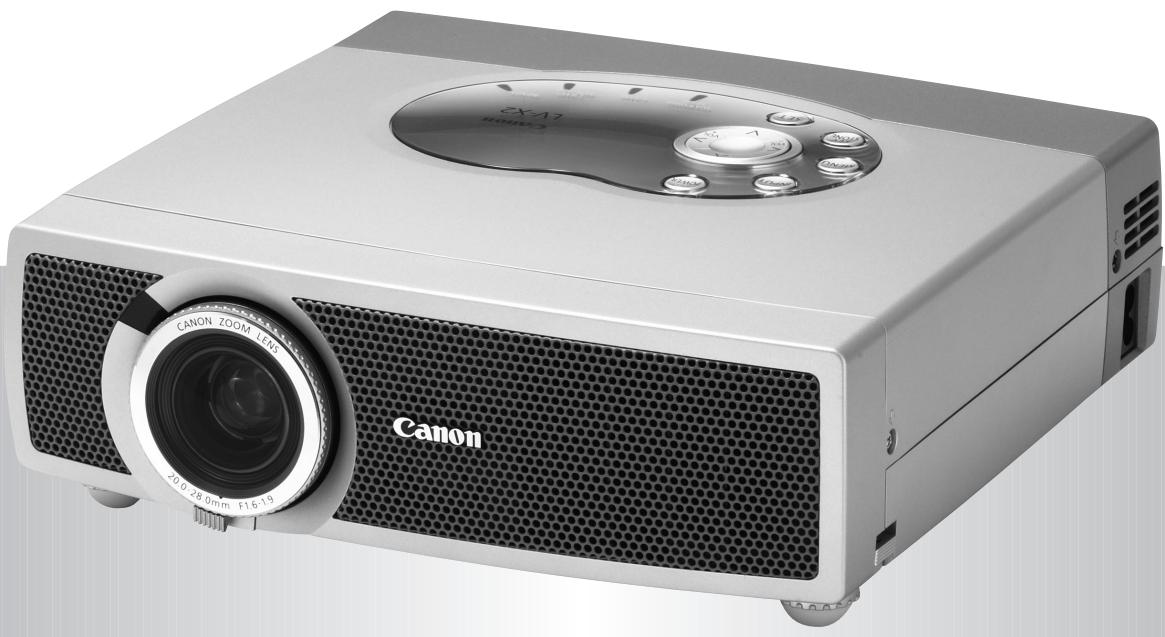
natural_image
Exterior view of a Canon projector with visible lens and control buttons (no text or symbols on body)TO THE OWNER
Before operating this projector, read this manual thoroughly to operate the projector properly.
This projector provides many convenient features and functions. Operating the projector properly enables you to manage those features and maintain it in better condition for a considerable time.
Improper operation may result in not only shortening the product-life, but also malfunctions, fire hazard, or other accidents.
If your projector seems to operate improperly, read this manual again, check operations and cable connections and try the solutions in the “TROUBLESHOOTING” section in the end at this manual. If the problem still persists, contact the sales dealer where you purchased the projector or the service center.

SAFETY PRECAUTIONS
WARNING : TO REDUCE THE RISK OF FIRE OR ELECTRIC SHOCK, DO NOT EXPOSE THIS APPLIANCE TO RAIN OR MOISTURE.
- This projector produces intense light from the projection lens. Do not stare directly into the lens as it could possibly damage your eyes. Be especially careful that children do not stare directly into the beam.
● This projector should be set in the way indicated. If not, it may result in a fire hazard.
● Take appropriate space on the top, sides and rear of the projector cabinet for allowing air circulation and cooling the projector. Minimum clearance must be maintained. If the projector is to be built into a compartment or similarly enclosed, the minimum distances must be maintained. Do not cover the ventilation slot on the projector. Heat build-up can reduce the service life of your projector, and can also be dangerous.
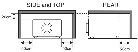
text_image
SIDE and TOP 20cm 50cm 50cm REAR 50cm- Do not put any flammable objects or spray cans near the projector, hot air is exhausted from the ventilation holes.
- If the projector is not to be used for an extended time, unplug the projector from the power outlet.
READ AND KEEP THIS OWNER'S MANUAL FOR LATER USE.
 |  RISK OF ELECTRIC SHOCKDO NOT OPEN RISK OF ELECTRIC SHOCKDO NOT OPEN |  |
| CAUTION: TO REDUCE THE RISK OF ELECTRIC SHOCK, DO NOT REMOVE COVER (OR BACK). NO USER-SERVICEABLE PARTS INSIDE EXCEPT LAMP REPLACEMENT. REFER SERVICING TO QUALIFIED SERVICE PERSONNEL. | ||
| THIS SYMBOL INDICATES THAT DANGEROUS VOLTAGE CONSTITUTING A RISK OF ELECTRIC SHOCK IS PRESENT WITHIN THIS UNIT. | THIS SYMBOL INDICATES THAT THERE ARE IMPORTANT OPERATING AND MAINTENANCE INSTRUCTIONS IN THE OWNER'S MANUAL WITH THIS UNIT. | |
All the safety and operating instructions should be read before the product is operated.
Read all of the instructions given here and retain them for later use. Unplug this projector from AC power supply before cleaning. Do not use liquid or aerosol cleaners. Use a damp cloth for cleaning.
Follow all warnings and instructions marked on the projector.
For added protection to the projector during a lightning storm, or when it is left unattended and unused for long periods of time, unplug it from the wall outlet. This will prevent damage due to lightning and power line surges.
Do not expose this unit to rain or use near water... for example, in a wet basement, near a swimming pool, etc...
Do not use attachments not recommended by the manufacturer as they may cause hazards.
Do not place this projector on an unstable cart, stand, or table. The projector may fall, causing serious injury to a child or adult, and serious damage to the projector. Use only with a cart or stand recommended by the manufacturer, or sold with the projector. Wall or shelf mounting should follow the manufacturer's instructions, and should use a mounting kit approved by the manufacturers.
An appliance and cart combination should be moved with care. Quick stops, excessive force, and uneven surfaces may cause the appliance and cart combination to overturn.

natural_image
Silhouette of a person pushing a ladder under a circular frame (no text or symbols)Slots and openings in the back and bottom of the cabinet are provided for ventilation, to insure reliable operation of the equipment and to protect it from overheating.
The openings should never be covered with cloth or other materials, and the bottom opening should not be blocked by placing the projector on a bed, sofa, rug, or other similar surface. This projector should never be placed near or over a radiator or heat register.
This projector should not be placed in a built-in installation such as a book case unless proper ventilation is provided.
Never push objects of any kind into this projector through cabinet slots as they may touch dangerous voltage points or short out parts that could result in a fire or electric shock. Never spill liquid of any kind on the projector.
This projector should be operated only from the type of power source indicated on the marking label. If you are not sure of the type of power supplied, consult your authorized dealer or local power company.
Do not overload wall outlets and extension cords as this can result in fire or electric shock. Do not allow anything to rest on the power cord. Do not locate this projector where the cord may be damaged by persons walking on it.
Do not attempt to service this projector yourself as opening or removing covers may expose you to dangerous voltage or other hazards. Refer all servicing to qualified service personnel.
Unplug this projector from wall outlet and refer servicing to qualified service personnel under the following conditions:
a. When the power cord or plug is damaged or frayed.
b. If liquid has been spilled into the projector.
c. If the projector has been exposed to rain or water.
d. If the projector does not operate normally by following the operating instructions. Adjust only those controls that are covered by the operating instructions as improper adjustment of other controls may result in damage and will often require extensive work by a qualified technician to restore the projector to normal operation.
e. If the projector has been dropped or the cabinet has been damaged.
f. When the projector exhibits a distinct change in performance—this indicates a need for service.
When replacement parts are required, be sure the service technician has used replacement parts specified by the manufacturer that have the same characteristics as the original part. Unauthorized substitutions may result in fire, electric shock, or injury to persons.
Upon completion of any service or repairs to this projector, ask the service technician to perform routine safety checks to determine that the projector is in safe operating condition.
Voor de klanten in Nederland

Bij dit product zijn batterijen geleverd.
Wanneer deze leeg zijn, moet u ze niet weggooien maar inleveren als KCA.
Federal Communication Commission Notice
Multimedia Projector, Model : LV-X2U, LV-X2E
This device complies with Part 15 of the FCC Rules. Operation is subject to the following two conditions:
(1) This device may not cause harmful interference, and
(2) this device must accept any interference received, including interference that may cause undesired operation.
Note : This equipment has been tested and found to comply with the limits for a Class B digital device, pursuant to part 15 of the FCC Rules. These limits are designed to provide reasonable protection against harmful interference in a residential installation. This equipment generates, uses and can radiate radio frequency energy and, if not installed and used in accordance with the instructions, may cause harmful interference to radio communications. However, there is no guarantee that interference will not occur in a particular installation. If this equipment does cause harmful interference to radio or television reception, which can be determined by turning the equipment off and on, the user is encouraged to try to correct the interference by one or more of the following measures :
– Reorient or relocate the receiving antenna.
– Increase the separation between the equipment and receiver.
- Connect the equipment into an outlet on a circuit different from that to which the receiver is connected.
- Consult the dealer or an experienced radio/TV technician for help.
Use of shielded cable is required to comply with class B limits in Subpart B of Part 15 of FCC Rules.
Do not make any changes or modifications to the equipment unless otherwise specified in the instructions. If such changes or modifications should be made, you could be required to stop operation of the equipment.
Canon U.S.A., Inc.
One Canon Plaza, Lake Success, NY 11042, U.S.A.
Tel No. (516)328-5600
For use in Germany
This product is intended for use in residential, commercial and light industry environment.
Canadian Radio Interference Regulations
This Class B digital apparatus meets all requirements of the Canadian Interference-Causing Equipment Regulations.
AC POWER CORD REQUIREMENT
The AC Power Cord supplied with this projector meets the requirement for use in the country you purchased it.
AC Power Cord for the United States and Canada :
AC Power Cord used in the United States and Canada is listed by the Underwriters Laboratories (UL) and certified by the Canadian Standard Association (CSA).
AC Power Cord has a grounding-type AC line plug. This is a safety feature to be sure that the plug will fit into the power outlet. Do not try to defeat this safety feature. Should you be unable to insert the plug into the outlet, contact your electrician.
text_image
GROUNDTHE SOCKET-OUTLET SHOULD BE INSTALLED NEAR THE EQUIPMENT AND EASILY ACCESSIBLE.
FEATURES AND DESIGN 6
PREPARATION 7
NOMENCHTOR 7
SETTING-UP THE PROJECTOR 8
CONNECTING AC POWER CORD 8
POSITIONING THE PROJECTOR 9
ADJUSTABLE FEET 9
MOUNTING THE LENS COVER 10
MOVING THE PROJECTOR 10
CONNECTING THE PROJECTOR 11
TERMINALS OF THE PROJECTOR 11
CONNECTING TO A COMPUTER 12
CONNECTING VIDEO EQUIPMENT 13
BEFORE OPERATION 14
OPERATION OF THE REMOTE CONTROL UNIT14
OPERATING RANGE 15
REMOTE CONTROL UNIT BATTERY INSTALLATION 15
TOP CONTROLS AND INDICATORS 16
OPERATING THE ON-SCREEN MENU 17
HOW TO OPERATE THE ON-SCREEN MENU 17
FLOW OF ON-SCREEN MENU OPERATION 17
MENU BAR 18
BASIC OPERATION 19
TURNING ON / OFF THE PROJECTOR 19
TURNING ON THE PROJECTOR 19
TURNING OFF THE PROJECTOR 19
ADJUSTING THE SCREEN 20
ZOOM ADJUSTMENT 20
FOCUS ADJUSTMENT 20
KEYSTONE ADJUSTMENT 20
PICTURE FREEZE FUNCTION 20
NO SHOW FUNCTION 21
P-TIMER FUNCTION 21
SOUND ADJUSTMENT 21
COMPUTER INPUT 22
SELECTING THE INPUT SOURCE 22
SELECTING THE COMPUTER SYSTEM 22
COMPATIBLE COMPUTER SPECIFICATIONS 23
PC ADJUSTMENT 24
AUTO PC ADJUSTMENT 24
MANUAL PC ADJUSTMENT 25
PICTURE IMAGE ADJUSTMENT 27
IMAGE LEVEL SELECT 27
IMAGE LEVEL ADJUSTMENT 28
PICTURE SCREEN ADJUSTMENT 29
VIDEO INPUT 30
SELECTING THE INPUT SOURCE 30
SELECTING THE VIDEO SYSTEM 31
PICTURE IMAGE ADJUSTMENT 32
IMAGE LEVEL SELECT 32
IMAGE LEVEL ADJUSTMENT 33
PICTURE SCREEN ADJUSTMENT 34
SETTING 35
SETTING MENU 35
APPENDIX 37
LAMP REPLACEMENT 37
LAMP REPLACE 37
LAMP REPLACE COUNTER 38
MAINTENANCE 39
WARNING TEMP. INDICATOR 39
AIR FILTER CARE AND CLEANING 39
CLEANING PROJECTION LENS 39
TROUBLESHOOTING 40
TECHNICAL SPECIFICATIONS 42
OPTIONAL PARTS 42
CONFIGURATIONS OF TERMINALS 43
TRADEMARKS
● Apple, Macintosh, and PowerBook are trademarks or registered trademarks of Apple Computer, Inc.
- IBM, VGA, XGA, and PS/2 are trademarks or registered trademarks of International Business Machines, Inc.
● Windows and PowerPoint are registered trademarks of Microsoft Corporation.
● Each name of corporations or products in the owner's manual is a trademark or a registered trademark of its respective corporation.
This Multimedia Projector is designed with the most advanced technology for portability, durability, and ease of use. It utilizes built-in multimedia features, a palette of 16.77 million colors, and matrix liquid crystal display (LCD) technology.
◆ Wide Zoom Lens
This projector is equipped with a Wide Zoom Lens with a 1.4 times optical zoom, and provides a 100" screen size at a range of 9.2' (2.8m) to 13.1' (4m).
◆ Compact Design
This projector is extremely compact in size and weight. It is designed to be carried and work anywhere.
◆ Compatibility
This projector accepts a wide range of video and computer input signals including;
● Computers
IBM-compatible or Macintosh computer up to 1280 x 1024 resolution.
● 6 Color TV Systems
NTSC, PAL, SECAM, NTSC 4.43, PAL-M or PAL-N color system can be connected.
● Component Video
Component video signal, such as a DVD player output high definition TV signals including 480i, 480p, 575i, 575p, 720p, 1035i or 1080i, can be connected.
● S-Video
S-Video signal, such as a S-VHS VCR or camcorder, can be connected.
◆ High Resolution Image
This projector provides 1024 x 768 dots resolution for computer input and 550 horizontal TV lines. Resolution from a computer between XGA (1024 x 768) and SXGA (1280 x 1024) is compressed into 1024 x 768 dots. This projector cannot display image of over 1280 x 1024 dots. When resolution of your computer is higher than 1280 x 1024, reset a computer output for lower resolution.
◆ Multi-Scan System
This projector has a Multi-Scan System to conform to recognition of almost all computer output signals allowing quick. Making manual adjustment of frequency and other settings unnecessary.
◆ One-Touch Auto PC Adjustment
Incoming computer video signals are recognized and the best adjustment is automatically set by Auto PC Adjustment.
◆ Digital Zoom (for Computer)
A Digital Zoom function lets you enlarge a sect of the image to 16 times, allowing you to focus on crucial information at a presentation.
♦ Keystone Correction
Positioning height of a projector may result in distorted image being displayed in a trapezoid shape. Keystone Correction solves this problem by digitally altering projection to produce undistorted images.
Power Management
Power Management function reduces power consumption while the projector is not in use.
This Power Management function operates to turn the Projection Lamp off when a signal has not been received or a button is not pressed over 5 minutes. Projection Lamp is automatically turned on again when a projector detects a signal or a button is pressed.
This projector is shipped with this function ON.
◆ Multilanguage Menu Display
Operation menu is displayed in; English, German, French, Italian, Spanish, Portuguese, Dutch, Swedish, Chinese, Korean or Japanese.
NOMENCHTOR
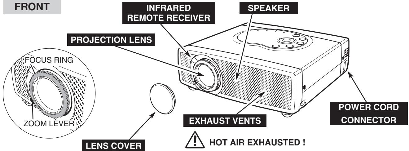
text_image
FRONT INFRARED REMOTE RECEIVER SPEAKER PROJECTION LENS FOCUS RING ZOOM LEVER LENS COVER EXHAUST VENTS POWER CORD CONNECTOR HOT AIR EXHAUSTED !Air blown from Exhaust Vents is hot. When using or installing the projector, the following precautions should be taken.
- Do not put any flammable object near these vents.
- Keep front grills at least 3'(1m) away from any object, especially heat-sensitive objects.
- Do not touch this area, especially screws and metallic parts. This area becomes hot while the projector is used.
BACK
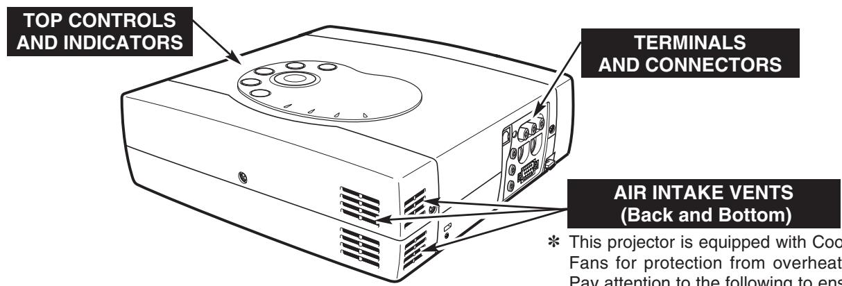
text_image
TOP CONTROLS AND INDICATORS TERMINALS AND CONNECTORS AIR INTAKE VENTS (Back and Bottom) * This projector is equipped with Cool Fans for protection from overheat. Pay attention to the following to ensAIR INTAKE VENTS (Back and Bottom)
* This projector is equipped with Cooling Fans for protection from overheating. Pay attention to the following to ensure proper ventilation and avoid a possible risk of fire and malfunction.
- Do not cover vent slots.
- Keep back and bottom clear of any object. Obstructions may block cooling air.
BOTTOM
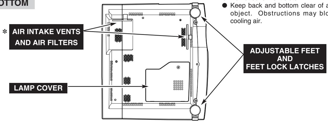
text_image
BOTTOM * AIR INTAKE VENTS AND AIR FILTERS LAMP COVER ● Keep back and bottom clear of a object. Obstructions may block cooling air. ADJUSTABLE FEET AND FEET LOCK LATCHESSETTING-UP THE PROJECTOR
CONNECTING AC POWER CORD
This projector uses nominal input voltages of 100-120 V or 200-240 V AC. This projector automatically selects the correct input voltage. It is designed to work with single-phase power systems having a grounded neutral conductor. To reduce risk of electrical shock, do not plug into any other type of power system.
Consult your authorized dealer or service station if you are not sure of the type of power being supplied.
Connect a projector with all peripheral equipment before turning a projector on. (Refer to pages 11 \~ 13 for connection.)

CAUTION
For safety, unplug AC Power Cord when the projector is not in use.
When this projector is connected to the outlet with AC Power Cord, it is in Stand-by Mode and consumes a little electric power.
natural_image
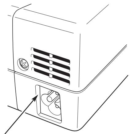
Line drawing of a microwave oven with ventilation slots and a vent (no text or symbols)Connect AC Power Cord (supplied) to a projector. The AC outlet must be near this equipment and must be easily accessible.
| NOTE ON THE POWER CORDAC Power Cord must meet requirements of the country where the projector is used.Confirm an AC plug type with the chart below and proper AC Power Cord must be used.If the supplied AC Power Cord does not match your AC outlet, contact your sales dealer. | ||
| Projector side | AC Outlet side | |
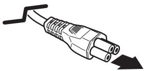 To POWER CORD CONNECTOR on your projector. To POWER CORD CONNECTOR on your projector. | For the U.S.A. and Canada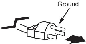 To the AC Outlet.(120 V AC) To the AC Outlet.(120 V AC) | For Continental Europe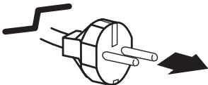 To the AC Outlet.(200 - 240 V AC) To the AC Outlet.(200 - 240 V AC) |
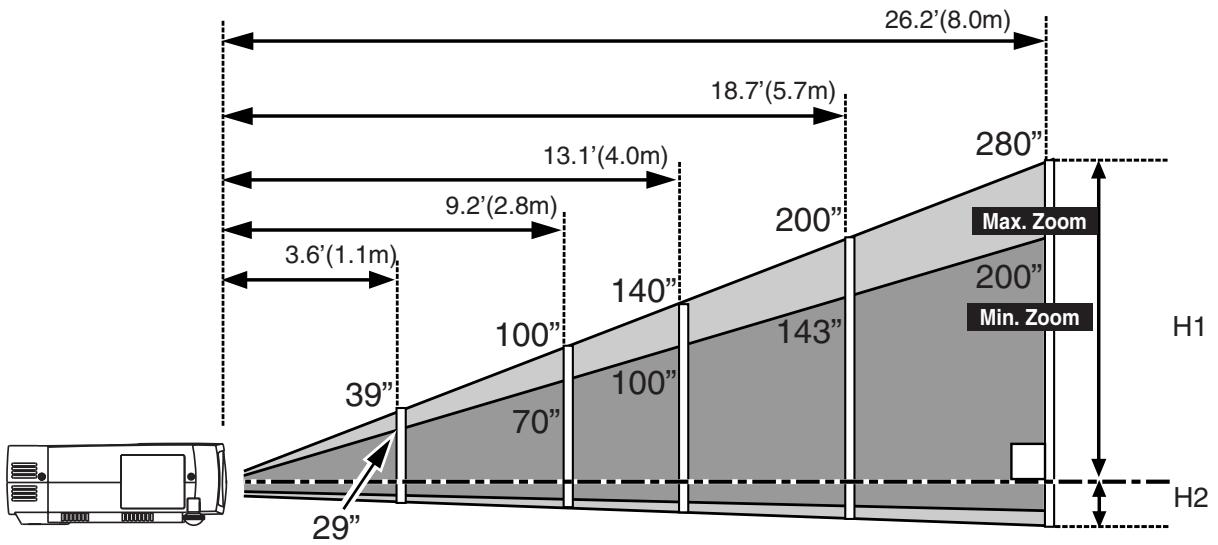
POSITIONING THE PROJECTOR
● This projector is designed to project on a flat projection surface.
● The projector can be focused from 3.6'(1.1m) \~ 26.2'(8m).
● Refer to the figure below to adjust a screen size.
ROOM LIGHT
The brightness of a room has a great impact on picture quality. It is recommended to limit ambient lighting to provide the best image.
other
| Section | Height (m) | | ------------- | ---------- | | Max. Zoom | 280 | | Min. Zoom | 200 | | Total Height | 26.2' | | Total Width | 3.6' | | Total Height | 18.7' | | Total Width | 13.1' | | Total Width | 9.2' | | Total Width | 39 || Screen Size (W x H) mm | 29" | 50" | 100" | 150" | 200" |
| 589 x 442 | 1016 x 762 | 2032 x 1524 | 3048 x 2286 | 4064 x 3048 | |
| Zoom (min) | 3.6' (1.1m) | 6.6' (2.0m) | 13.1' (4.0m) | 19.7' (6.0m) | 26.2' (8.0m) |
| Zoom (max) | —— | 4.6' (1.4m) | 9.2' (2.8m) | 14.1' (4.3m) | 18.7' (5.7m) |
* The projection maximum screen size is 200".
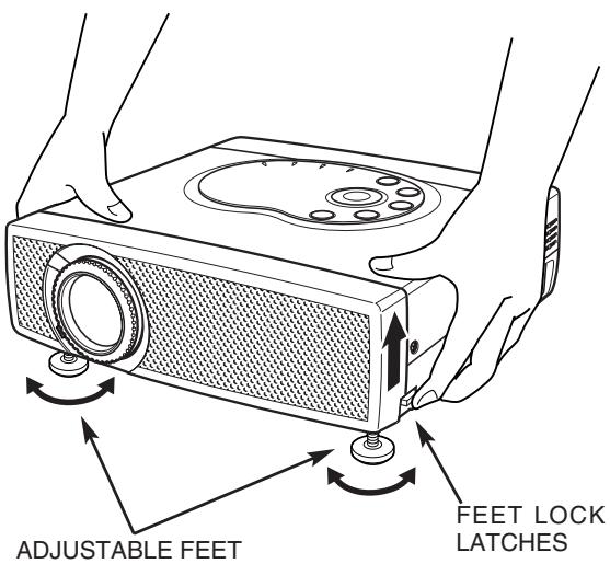
ADJUSTABLE FEET
Picture tilt and projection angle can be adjusted by rotating the ADJUSTABLE FEET. Projection angle can be adjusted to approx. 10 degrees.
1 Lift the front of the projector and pull the FEET LOCK LATCHES on both sides of a projector.
2 Release the FEET LOCK LATCHES to lock the ADJUSTABLE FEET and rotate the ADJUSTABLE FEET to adjust position and tilt.
3 To retract the ADJUSTABLE FEET, lift the front of the projector and pull the FEET LOCK LATCHES and push to feet upward.
Keystone distortion of a projected image can be adjusted by Menu Operation. (Refer to P20 and 35.)

CAUTION
Avoid positioning a projector with the angle of more than 20 degrees. Projection Lamp may malfunction.
text_image
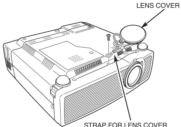
ADJUSTABLE FEET FEET LOCK LATCHESMOUNTING THE LENS COVER
When transporting the projector or when it is not used for an extended period of time, attach the Lens Cover.
Before attaching the Lens Cover, be sure to turn the projector off and disconnect the AC Power cord from the AC outlet.
1 Secure the Strap for the Lens Cover through the hole.
2 Turn the projector upside down and secure the Strap for the Lens Cover to the bottom of projector with a screw.
text_image
LENS COVER STRAP FOR LENS COVERSTRAP FOR LENS COVER
Secure to the hole with a screw.
MOVING THE PROJECTOR
When moving a projector, attach the Lens Cover and retract the Adjustable Feet to prevent damage to the lens and cabinet. When the projector is not in use for an extended period, put it into the case (carrying bag) supplied with the projector.

CAUTION
Carrying Bag (supplied) is intended for protection from dust and scratches on the surface of a cabinet, and it is not designed to protect the projector from external forces. Do not transport a projector through a courier or transport services with this bag, otherwise the projector can be damaged. When handling a projector, do not drop, bump, subject it to strong forces or put other things on the cabinet.

CAUTION IN CARRYING OR TRANSPORTING THE PROJECTOR
- Do not drop or bump a projector, otherwise damage or malfunction may result.
- When carrying a projector, use a suitable carrying case.
- Do not transport a projector by using a courier or transport service in an unsuitable transport case. This may cause damage to the projector. To transport the projector through a courier or transport service, consult your dealer.
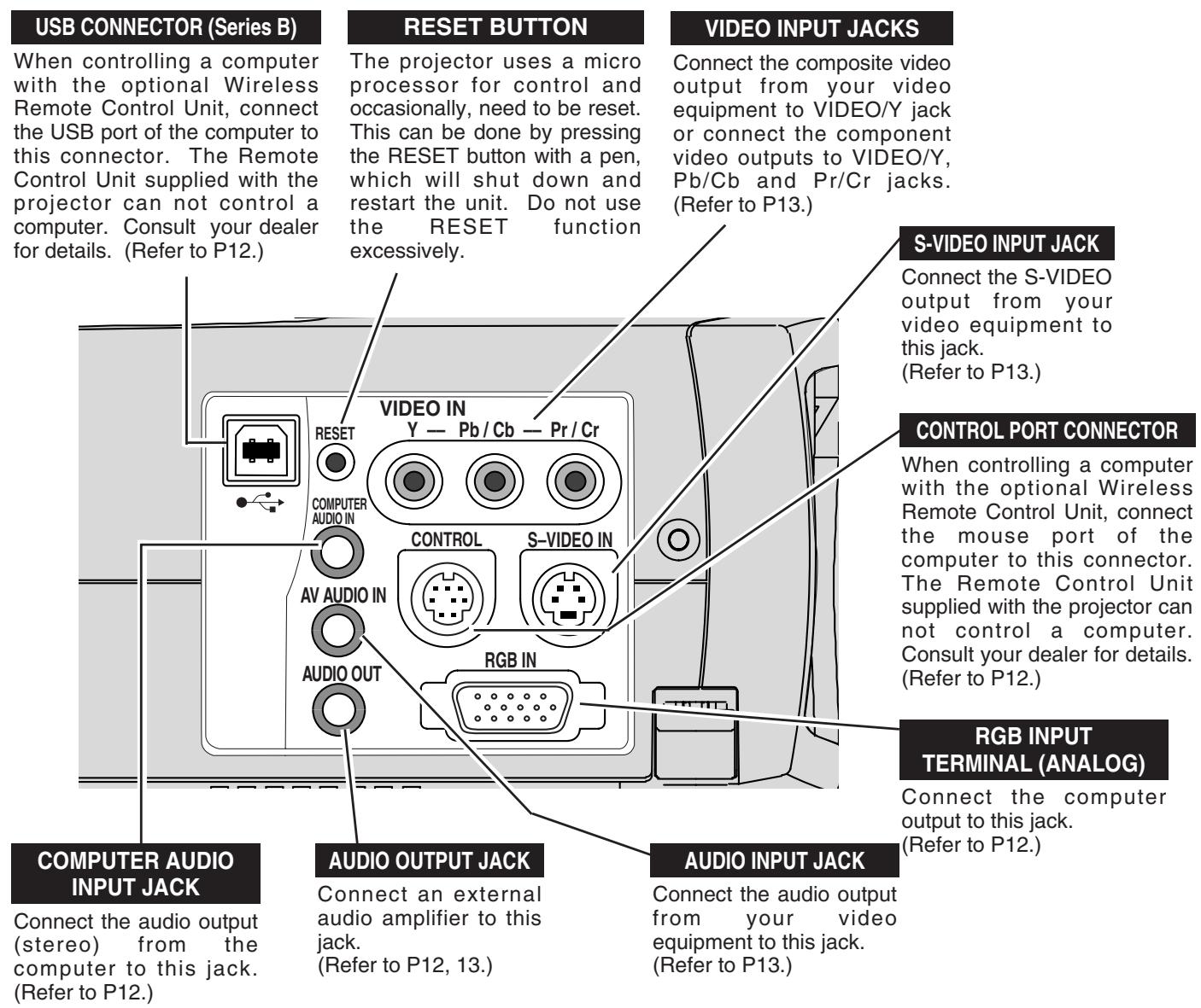
TERMINALS OF THE PROJECTOR
This projector has input and output terminals on its side for connecting computer and video equipment. Refer to figures on pages 11 to 13 for these connections.
text_image
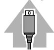
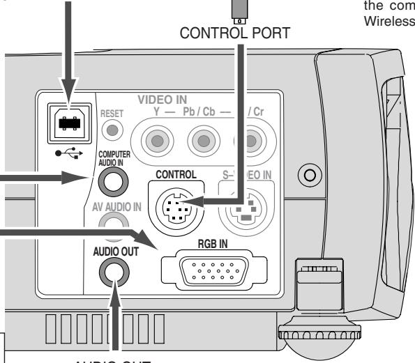
USB CONNECTOR (Series B) When controlling a computer with the optional Wireless Remote Control Unit, connect the USB port of the computer to this connector. The Remote Control Unit supplied with the projector can not control a computer. Consult your dealer for details. (Refer to P12.) RESET BUTTON The projector uses a micro processor for control and occasionally, need to be reset. This can be done by pressing the RESET button with a pen, which will shut down and restart the unit. Do not use the RESET function excessively. VIDEO INPUT JACKS Connect the composite video output from your video equipment to VIDEO/Y jack or connect the component video outputs to VIDEO/Y, Pb/Cb and Pr/Cr jacks. (Refer to P13.) S-VIDEO INPUT JACK Connect the S-VIDEO output from your video equipment to this jack. (Refer to P13.) CONTROL PORT CONNECTOR When controlling a computer with the optional Wireless Remote Control Unit, connect the mouse port of the computer to this connector. The Remote Control Unit supplied with the projector can not control a computer. Consult your dealer for details. (Refer to P12.) RGB INPUT TERMINAL (ANALOG) Connect the computer output to this jack. (Refer to P12.) COMPUTER AUDIO INPUT JACK Connect the audio output (stereo) from the computer to this jack. (Refer to P12.) AUDIO OUTPUT JACK Connect an external audio amplifier to this jack. (Refer to P12, 13.) AUDIO INPUT JACK Connect the audio output from your video equipment to this jack. (Refer to P13.)CONNECTING TO A COMPUTER
Cables used for connection (* = Cable or adapter is not supplied with this projector.)
• VGA Cable (HDB 15 pin)
- MAC Adapter (When connecting to Macintosh computer) *
- Control Cable for PS/2 Port *, Serial Port *, or ADB Port *
• Audio Cable (Mini Plug (stereo) x 1) *
- USB Cable *
IBM-compatible computer or Macintosh computer (VGA / SVGA / XGA / SXGA)
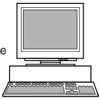
Desktop type
natural_image
Line drawing of a desktop computer with monitor, keyboard, and mouse (no text or symbols)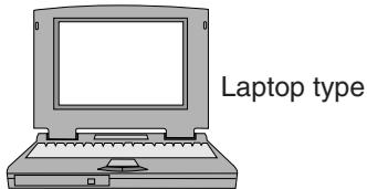
text_image
Laptop typeMonitor Output
MAC Adapter *
Set slide switches according to the chart below.
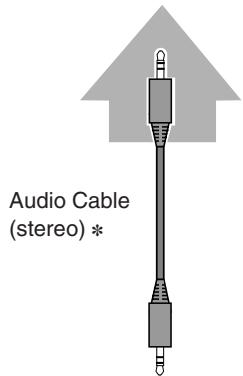
Audio Output
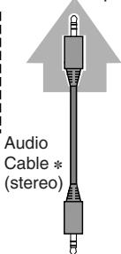
text_image
Audio Cable * (stereo)USB port Se

Serial port

PS/2 port

ADB port
Control Cable for Serial Port *
Control Cable for PS/2 Port *
Control Cable for ADB Port *


VGA Cable
RGB IN
COMPUTER AUDIO IN
USB
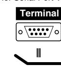
Use one of these Control Cables or USB Cable corresponding with the terminal of your computer only when controlling the computer with the optional Wireless Remote Control Unit.
text_image
CONTROL PORT VIDEO IN Y — Pb / Cb — / Cr RESET COMPUTER AUDIO IN AV AUDIO IN CONTROL S—VIDEO IN AUDIO OUT RGB IN the com Wireless
NOTE :
When connecting the cable, the power cords of both the projector and the external equipment should be disconnected from AC outlet. Turn the projector and peripheral equipment on before the computer is switched on.
AUDIO OUT
text_image
Audio Cable (stereo) *Terminals of the Projector
◆ MAC ADAPTER (Not supplied)
Set switches as shown in the table below depending on RESOLUTION MODE that you want to use before you turn on projector and computer.
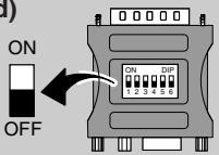
| 1 | 2 | 3 | 4 | 5 | 6 | |
| 13" MODE (640 x 480) | ON | ON | OFF | OFF | OFF | OFF |
| 16" MODE (832 x 624) | OFF | ON | OFF | ON | OFF | OFF |
| 19" MODE (1024 x 768) | OFF | ON | ON | OFF | OFF | OFF |
| 21" MODE (1152 x 870) | ON | ON | ON | ON | OFF | OFF |
External Audio Equipment
Audio Amplifier
Audio Speaker (stereo)


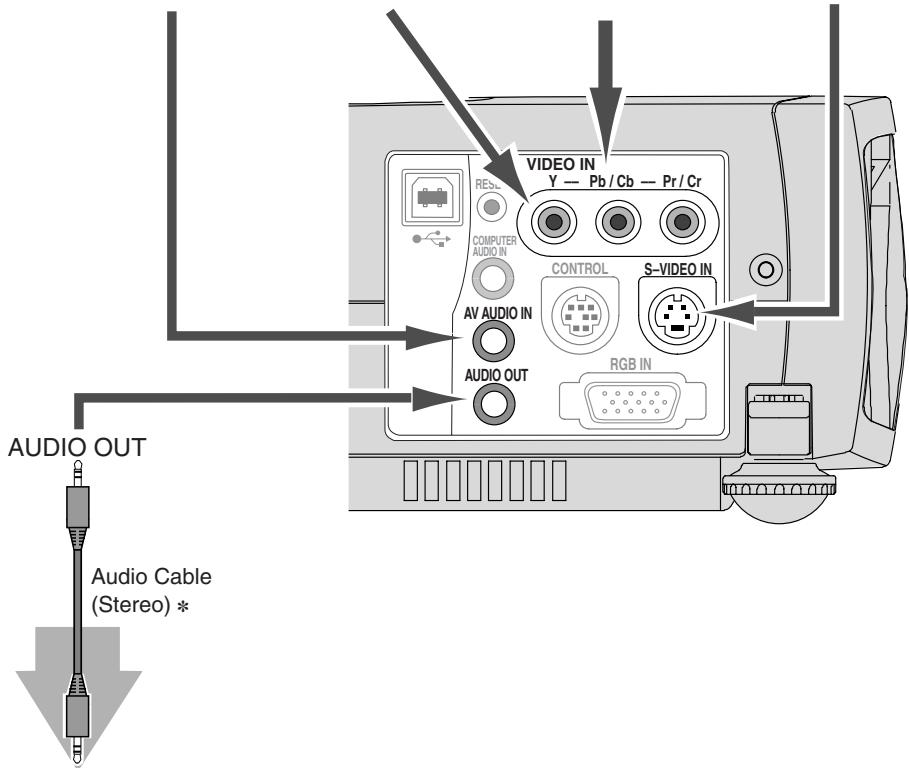
CONNECTING VIDEO EQUIPMENT
Cables used for connection (\* = Cable is not supplied with this projector.)
• Video Cable (RCA x 1 or RCA x 3) *
- S-VIDEO Cable *
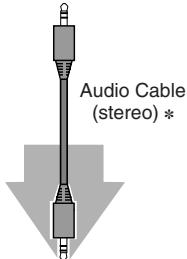
• Audio Cable (Mini Plug (stereo) x 1) *
Video Source (example)
Video Cassette Recorder

Video Disc Player

Component video output equipment.
(such as DVD player or high-definition
TV source.)

Audio Output
text_image
Audio Cable (stereo) *Composite
Video Output
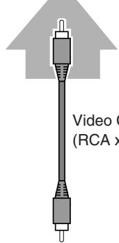
text_image
Video (RCA)Component Video Output
(Y, Pb/Cb, Pr/Cr)
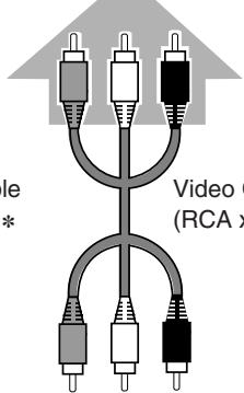
text_image
Video (RCA)S-VIDEO Output
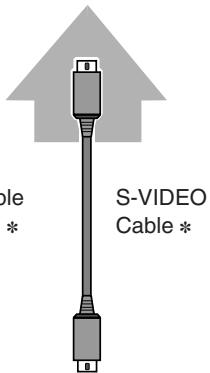
text_image
S-VIDEO Cable * * Cable *AV AUDIO IN
VIDEO
Y - Pb/Cb - Cr/Pr
S-VIDEO IN
text_image
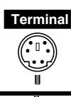
AUDIO OUT Audio Cable (Stereo) * VIDEO IN Y — Pb / Cb — Pr / Cr COMPUTER AUDIO IN AV AUDIO IN CONTROL S-VIDEO IN AUDIO OUT RGB INUse any of VIDEO jack Y-Pb/Cb-Pr/Cr jacks or S-VIDEO jack.
- When both VIDEO jack and S-VIDEO jack are connected, S-VIDEO jack has priority over VIDEO jack.
- When both Y-Pb/Cb-Pr/Cr jacks and S-VIDEO jack are connected, Y-Pb/Cb-Pr/Cr jacks has priority over S-VIDEO jack.
Terminals the Projector
Audio Input
External Audio Equipment
Audio Amplifier

Audio Speaker (stereo)


NOTE :
When connecting the cable, the power cords of both the projector and the external equipment should be disconnected from AC outlet.
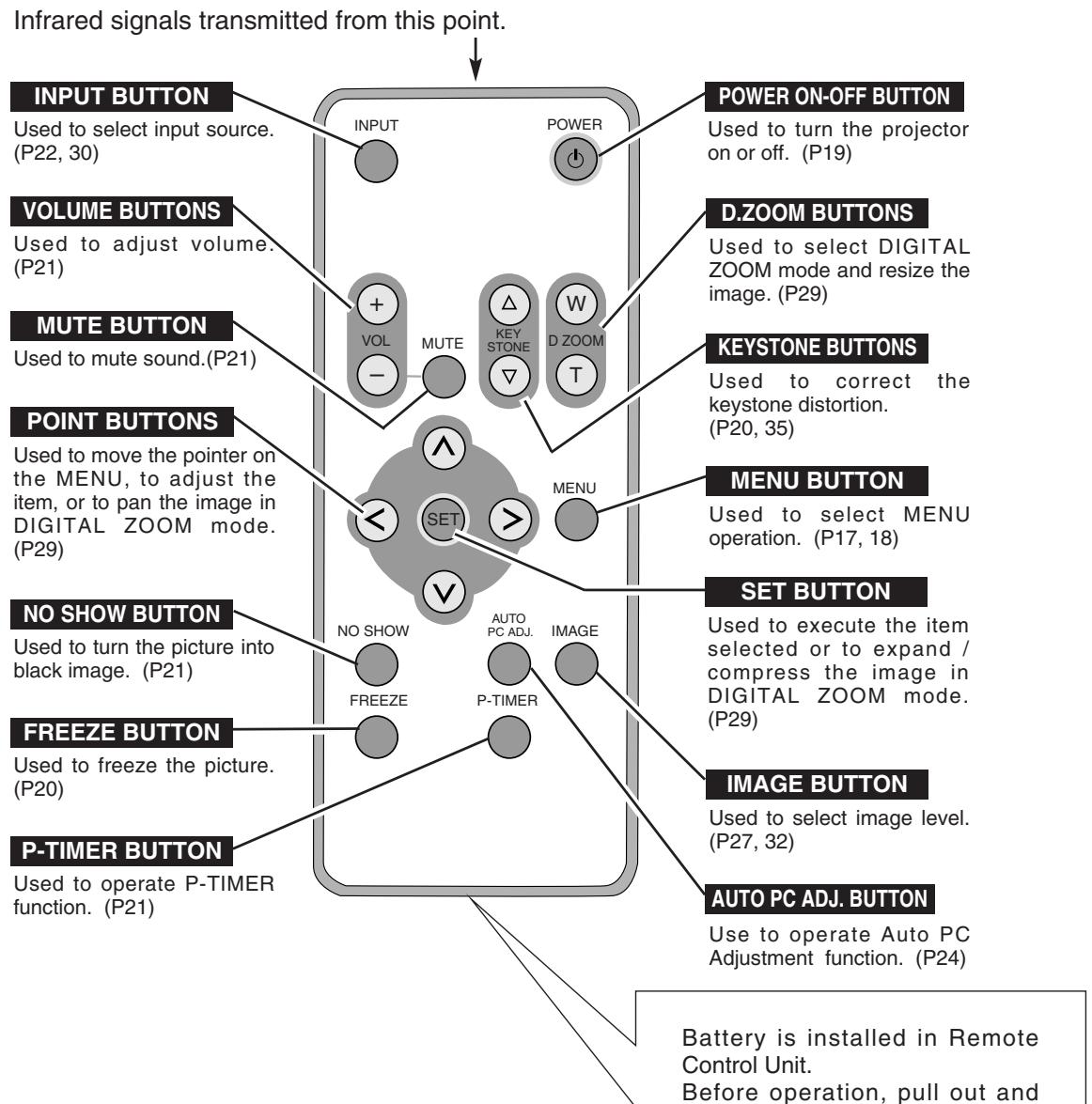
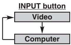
OPERATION OF THE REMOTE CONTROL UNIT
flowchart
graph TD
    A["Input Button"] --> B["Volume Buttons"]
    B --> C["MUTE BUTTON"]
    C --> D["POINT BUTTONS"]
    D --> E["NO SHOW BUTTON"]
    E --> F["FREEZE BUTTON"]
    F --> G["P-TIMER BUTTON"]
    G --> H["Output Function (P21)"]

    I["POWER ON-OFF BUTTON"] --> J["D.ZOOM BUTTONS"]
    J --> K["KEYSTONE BUTTONS"]
    K --> L["MENU BUTTON"]
    L --> M["SET BUTTON"]
    M --> N["IMAGE BUTTON"]
    N --> O["AUTO PC ADJ. BUTTON"]

    style I fill:#f9f,stroke:#333
    style J fill:#ccf,stroke:#333
    style K fill:#cfc,stroke:#333
    style L fill:#fcc,stroke:#333
    style M fill:#cff,stroke:#333
    style N fill:#ffc,stroke:#333
    style O fill:#fcc,stroke:#333

To insure safe operation, please observe the following precautions :
- Do not bend, drop Remote Control Unit, or expose Remote Control Unit to moisture or heat.
- For cleaning, use soft dry cloth. Do not apply benzene, thinner, splay or any chemical material.
Battery is installed in Remote Control Unit.
Before operation, pull out and remove a protect sheet from Remote Control Unit. This sheet protecting discharge of a battery.
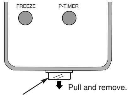
text_image
FREEZE P-TIMER Pull and remove.BATTERY PROTECT SHEET (transparent sheet)
OPERATING RANGE
Point Remote Control Unit toward projector (Receiver Window) whenever pressing any button. Maximum operating range for Remote Control Unit is about 16.4' (5m) and 60° in front of the projector.
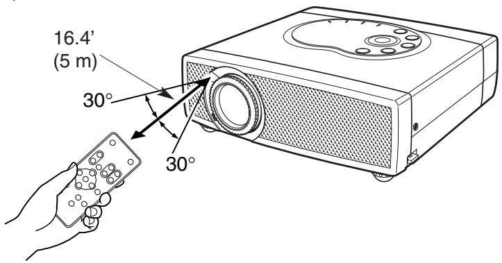
text_image
16.4' (5 m) 30° 30°REMOTE CONTROL UNIT BATTERY INSTALLATION
1 Pull out Battery Holder.
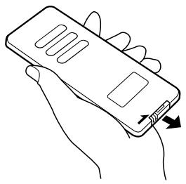
natural_image
Line drawing of a hand holding a smartphone with a USB cable (no text or symbols)2 Replace with new battery. Install with battery (+),(-) marks properly.
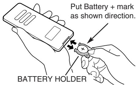
text_image
Put Battery + mark as shown direction. BATTERY HOLDER3 Install battery and Battery Holder into Remote Control Unit.
BATTERY
LITHIUM BATTERY CR2025 (3.0V)


To insure safe operation, please observe the following precautions :
● Use only specified battery. Improper battery may cause malfunction of Remote Control Unit.
- Be sure to install battery with correct polarity.
- Do not expose a battery to moisture or heat. Do not charge a battery.
- If a battery has leaked on the Remote Control Unit, carefully wipe the case clean and load a new battery.
- Keep a battery away from children to avoid swallowing it accidentally.
● Risk of explosion if battery is replaced by an incorrect type.
- Dispose of used batteries according to the instructions.
TOP CONTROLS AND INDICATORS
text_image
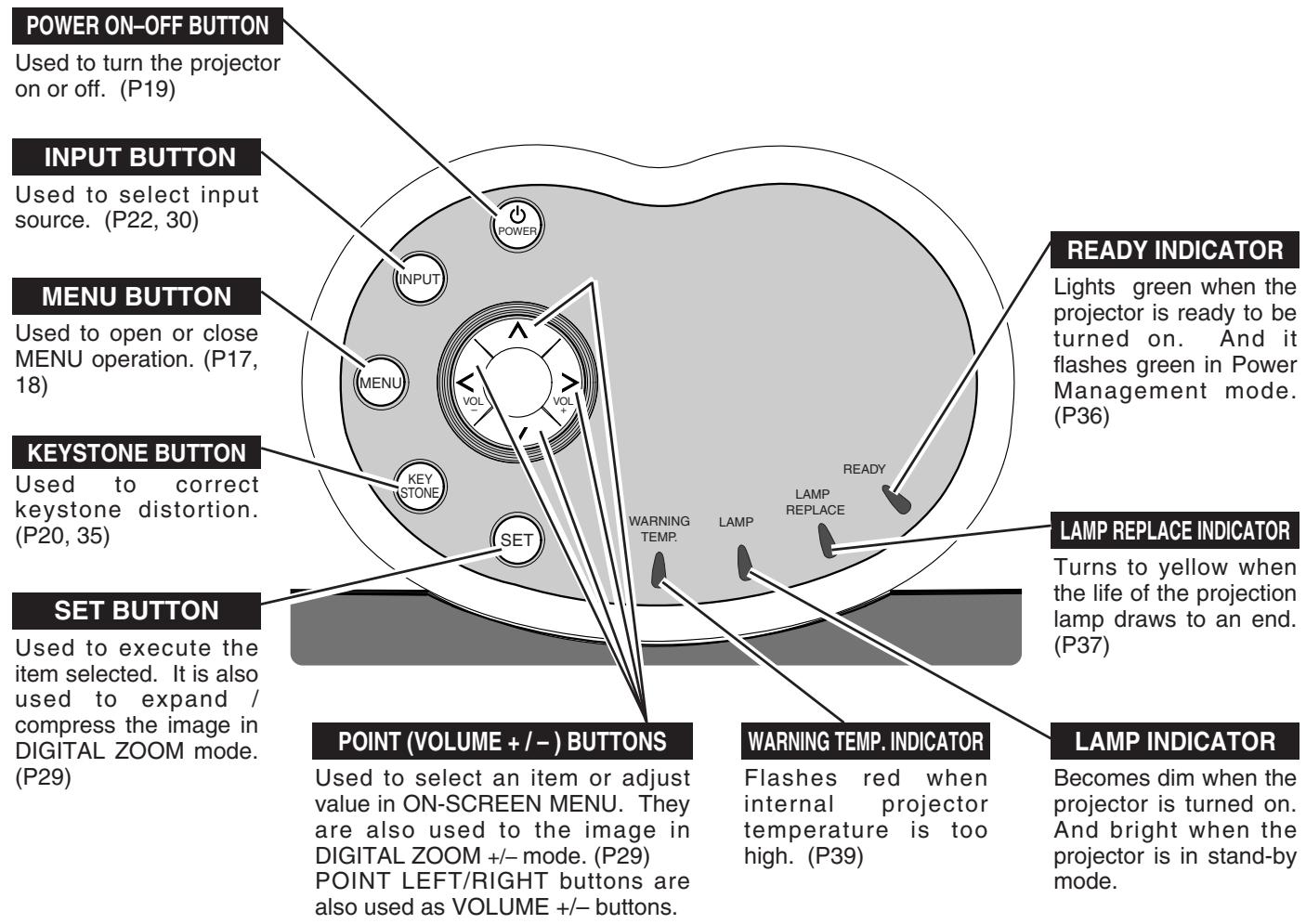
POWER ON-OFF BUTTON Used to turn the projector on or off. (P19) INPUT BUTTON Used to select input source. (P22, 30) MENU BUTTON Used to open or close MENU operation. (P17, 18) KEYSTONE BUTTON Used to correct keystone distortion. (P20, 35) SET BUTTON Used to execute the item selected. It is also used to expand / compress the image in DIGITAL ZOOM mode. (P29) POINT (VOLUME +/−) BUTTONS Used to select an item or adjust value in ON-SCREEN MENU. They are also used to the image in DIGITAL ZOOM +/- mode. (P29) POINT LEFT/RIGHT buttons are also used as VOLUME +/- buttons. READY INDICATOR Lights green when the projector is ready to be turned on. And it flashes green in Power Management mode. (P36) LAMP REPLACE INDICATOR Turns to yellow when the life of the projection lamp draws to an end. (P37) WARNING TEMP. INDICATOR Flashes red when internal projector temperature is too high. (P39) LAMP INDICATOR Becomes dim when the projector is turned on. And bright when the projector is in stand-by mode.OPERATING THE ON-SCREEN MENU
HOW TO OPERATE THE ON-SCREEN MENU
You can control and adjust this projector through the ON-SCREEN MENU. Refer to the following pages to operate each adjustment on ON-SCREEN MENU.
DISPLAY MENU
1 Press MENU button to display ON-SCREEN MENU.
MOVING POINTER
2 Move the pointer (* see below) or adjust the value of item by pressing POINT button(s) on Top Control or on Remote Control Unit.
* Pointer is the icon on ON-SCREEN MENU to select the item. See the figures on the section "FLOW OF ON-SCREEN MENU OPERATION" below.
SELECT ITEM
3 Select the item or set selected function by pressing SET button.
REMOTE CONTROL UNIT
text_image
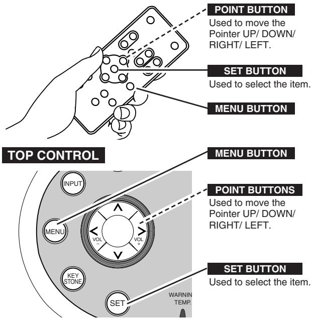
POINT BUTTON Used to move the Pointer UP/ DOWN/ RIGHT/ LEFT. SET BUTTON Used to select the item. MENU BUTTON TOP CONTROL MENU BUTTON POINT BUTTONS Used to move the Pointer UP/ DOWN/ RIGHT/ LEFT. SET BUTTON Used to select the item. INPUT MENU VOL VOL KEY STONE SET WARNING TEMP.FLOW OF ON-SCREEN MENU OPERATION
Display ON-SCREEN MENU
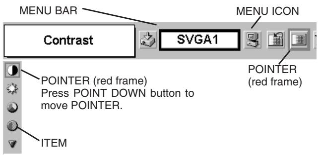
1 Press MENU button to display ON-SCREEN MENU (MENU BAR). The red frame is the POINTER.
Select Menu to be adjusted
2 Move POINTER (red frame) to MENU ICON that you want to select by pressing POINT RIGHT / LEFT buttons.
Control or adjust item through ON-SCREEN MENU
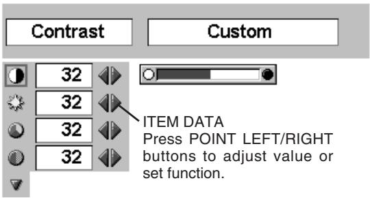
3 Press POINT DOWN button and move POINTER (red frame or red arrow) to the ITEM that you want to adjust, and then press the SET button to show the DATA.
4 Adjust the ITEM DATA by pressing the POINT RIGHT / LEFT buttons.
Refer to the following pages for details of respective adjustments.
text_image
MENU BAR Contrast SVGA1 MENU ICON POINTER (red frame) Press POINT DOWN button to move POINTER. ITEM
text_image
Contrast Custom 32 32 32 32 ITEM DATA Press POINT LEFT/RIGHT buttons to adjust value or set function.MENU BAR
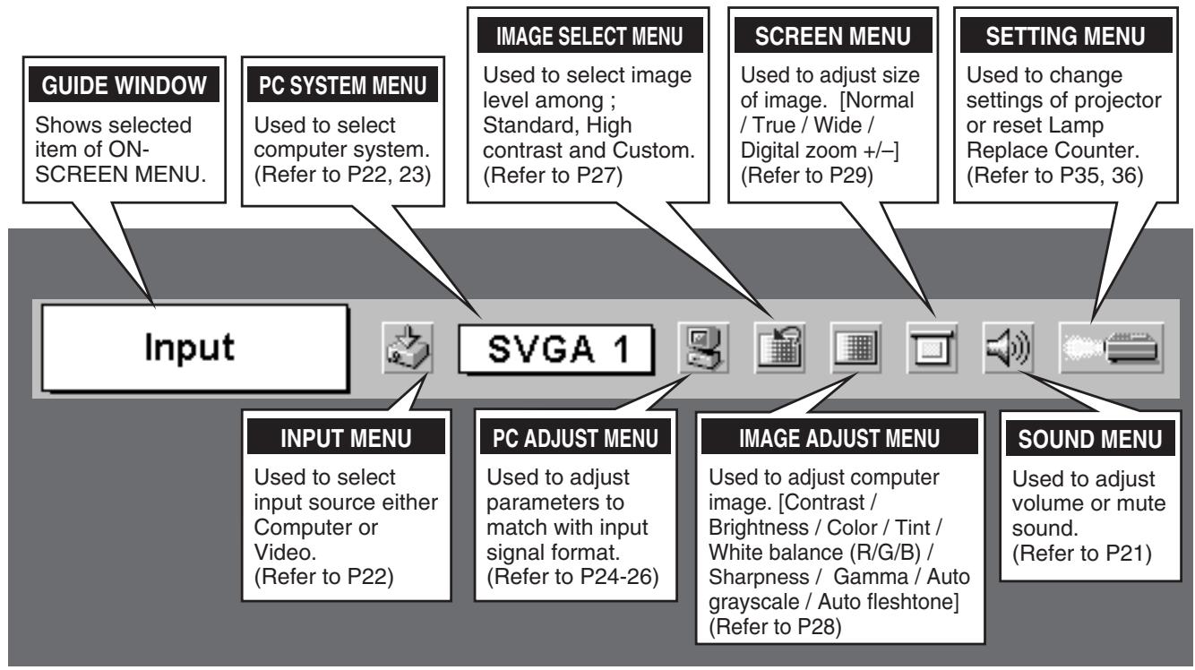
FOR PC SOURCE
Press the MENU BUTTON while connected to the PC input source.
flowchart
graph TD
    A["Input"] --> B["GUIDE WINDOW"]
    A --> C["PC SYSTEM MENU"]
    A --> D["IMAGE SELECT MENU"]
    A --> E["SCREEN MENU"]
    A --> F["SETTING MENU"]
    A --> G["INPUT MENU"]
    A --> H["PC ADJUST MENU"]
    A --> I["IMAGE ADJUST MENU"]
    A --> J["SOUND MENU"]
    B --> K["Shows selected item of ON-SCREEN MENU."]
    C --> L["Used to select computer system. (Refer to P22, 23)"]
    D --> M["Used to select image level among ; Standard, High contrast and Custom. (Refer to P27)"]
    E --> N["Used to adjust size of image. [Normal / True / Wide / Digital zoom +/-"] (Refer to P29)]
    F --> O["Used to change settings of projector or reset Lamp Replace Counter. (Refer to P35, 36)"]
    G --> P["Used to select input source either Computer or Video. (Refer to P22)"]
    H --> Q["Used to adjust parameters to match with input signal format. (Refer to P24-26)"]
    I --> R["Used to adjust computer image. [Contrast / Brightness / Color / Tint / White balance (R/G/B) / Sharpness / Gamma / Auto grayscale / Auto fleshtone"] (Refer to P28)]
    J --> S["Used to adjust volume or mute sound. (Refer to P21)"]
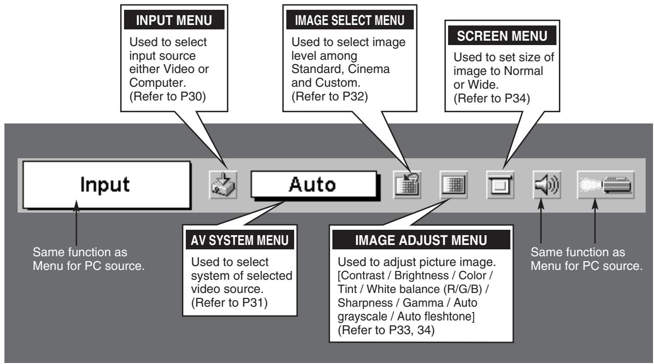
FOR VIDEO SOURCE
Press the MENU BUTTON while connecting to the VIDEO input source.
flowchart
graph TD
    A["Input"] --> B["AV SYSTEM MENU"]
    A --> C["IMAGE ADJUST MENU"]
    B --> D["Image Select Menu"]
    C --> E["Screen Menu"]
    D --> F["Input Menu"]
    E --> G["Image Select Menu"]
    style A fill:#f9f,stroke:#333
    style B fill:#ccf,stroke:#333
    style C fill:#cfc,stroke:#333
    style D fill:#fcc,stroke:#333
    style E fill:#cff,stroke:#333
    style F fill:#ffc,stroke:#333
    style G fill:#fcc,stroke:#333
TURNING ON / OFF THE PROJECTOR
TURNING ON THE PROJECTOR
1 Complete peripheral connections (with Computer, VCR, etc.) before turning on the projector. (Refer to "CONNECTING PROJECTOR" on page 11\~13 for connecting the equipment.)
2 Connect the projector's AC Power Cord into an AC outlet. LAMP Indicator lights red, and READY Indicator lights green.
3 Press POWER ON-OFF button on Top Control or on Remote Control Unit to ON. LAMP Indicator dims, and Cooling Fans start to operate. Preparation Display appears on a screen and the count-down starts. The signal from PC or Video source appears after 30 seconds. And then current image level is displayed on screen for 4 seconds.
text_image
30Preparation Display disappears after 30 seconds.
text_image
StandardCurrent image level is displayed on screen for 4 seconds.
TURNING OFF THE PROJECTOR
1 Press POWER ON-OFF button on Top Control or on Remote Control Unit, and a message "Power off?" appears on a screen.
2 Press POWER ON-OFF button again to turn off the projector. LAMP Indicator lights bright and READY Indicator turns off. After the projector is turned off, Cooling Fans operate (for 90 seconds).
3 When the projector has cooled down, READY Indicator lights green again.
NOTE : Projector cannot be turned on during cooling period with READY Indicator off. You can turn it on again after READY Indicator lights green.
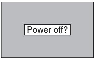
text_image
Power off?Message disappears after 4 seconds.

TO MAINTAIN THE LIFE OF LAMP, ONCE YOU TURN PROJECTOR ON, WAIT AT LEAST 5 MINUTES BEFORE TURNING IT OFF. DO NOT DISCONNECT AC POWER CORD BEFORE READY INDICATOR LIGHTS GREEN.
note on operation
When “Power management” function is ON, the projector detects signal interruption and turns off Projection Lamp automatically. Refer to “Power management” on page 36.
When WARNING TEMP. Indicator flashes red, the projector is automatically turned off. Wait at least 5 minutes before turning on the projector again.
When WARNING TEMP. Indicator continues to flash, follow the procedures below:
- Press POWER ON-OFF button to turn the projector off and disconnect AC Power Cord from an AC outlet.
- Check Air Filters for dust accumulation.
- Clean Air Filters. (See "AIR FILTER CARE AND CLEANING" section on page 39.)
- Turn the projector on again.
If WARNING TEMP. Indicator continues to flash, contact your sales dealer or service center.
ADJUSTING THE SCREEN
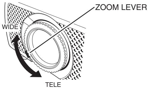
ZOOM ADJUSTMENT
Move ZOOM LEVER upward to make the image larger. Move ZOOM LEVER downward to make the image smaller.
text_image
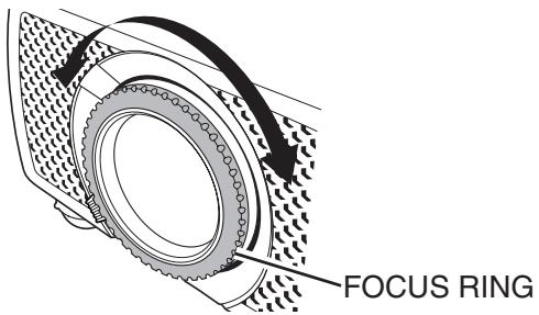
ZOOM LEVER WIDE TELEFOCUS ADJUSTMENT
Rotate the FOCUS RING to adjust the projected picture focus.
text_image
FOCUS RINGKEYSTONE ADJUSTMENT
If a projected picture has keystone distortion, correct image with KEYSTONE adjustment.
1 Press KEYSTONE ▲/▼ button on Remote Control Unit or KEYSTONE button on Top Control or select Keystone on SETTING menu. (Refer to page 35.) Keystone dialog box appears.
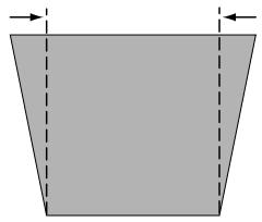
2 Correct keystone distortion by pressing KEYSTONE ▲/▼ button or POINT UP/DOWN button(s). Press KEYSTONE ▲ button or POINT UP button to reduce the upper part of image, and press KEYSTONE ▼ button or POINT DOWN button to reduce the lower part.
Reduce the upper width with KEYSTONE ▲ button or POINT UP button.
natural_image
Simple geometric diagram of a trapezoid with dashed vertical lines and arrows indicating width (no text or symbols)Keystone

- Arrows are white in no correction.
- Arrow of direction being corrected turns blue.
- Arrow disappears at the maximum correction.
Reduce the lower width with KEYSTONE ▼ button or POINT DOWN button.
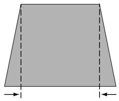
natural_image
Simple geometric diagram of a trapezoid with dashed lines indicating vertical and horizontal dimensions (no text or labels)PICTURE FREEZE FUNCTION
Press the FREEZE button on the Remote Control Unit to freeze the picture on-screen. To cancel the FREEZE function, press the FREEZE button again or press any other button.
NO SHOW FUNCTION
Press the NO SHOW button on the Remote Control Unit to black out the image. To restore to normal, press the NO SHOW button again or press any other button.
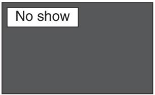
text_image
No showMessage disappears after 4 seconds.
P-TIMER FUNCTION
Press the P-TIMER button on the Remote Control Unit. The timer display "00 : 00" appears on the screen and the timer starts to count time (00 : 00 \~ 59 : 59).
To stop the P-TIMER display, press the P-TIMER button. Press the P-TIMER button again to cancel the P-TIMER function.

text_image
Digital display showing a clock icon and four vertical bars with varying widths, likely representing time or duration.SOUND ADJUSTMENT
DIRECT OPERATION
Volume
Press the VOLUME (+/-) button(s) on the Remote Control Unit or POINT LEFT / RIGHT (VOL -/+ ) button on Top Control to adjust volume. The volume dialog box appears on the screen for a few seconds.
Use the VOLUME (+) or POINT RIGHT (VOL +) button to increase volume, and VOLUME (−) or POINT LEFT (VOL −) button for decreasing.
Mute
Press MUTE button on Remote Control Unit to cut off the sound. To restore sound to its previous level, press MUTE button again or press Volume (+/-) or POINT LEFT / RIGHT (VOL -/+) button(s).
MENU OPERATION
1 Press the MENU button and the ON-SCREEN MENU will appear. Press the POINT LEFT/RIGHT buttons to move the red frame to SOUND Menu icon.
2 Press the POINT DOWN button to move the red frame to the item that you want to select, and then press SET button.

Volume
To increase the volume, press the POINT RIGHT (VOL +) button, and press the POINT LEFT (VOL -) button for decreasing.

Mute
Press the POINT LEFT/RIGHT button(s) (VOL -/+ ) to cut off sound. The dialog box display is changed to "On" and sound is cut off. To restore sound to its previous level, press the POINT LEFT/RIGHT (VOL -/+) button(s) again.
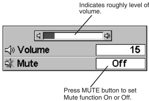
text_image
Indicates roughly level of volume. Volume 15 Mute Off Press MUTE button to set Mute function On or Off.The display disappears after 4 seconds.
SOUND MENU
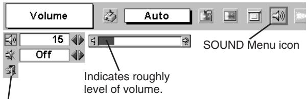
text_image
Volume 15 Off Auto SOUND Menu icon Indicates roughly level of volume.Close SOUND Menu.
SELECTING THE INPUT SOURCE
DIRECT OPERATION
Choose Computer by pressing the INPUT button on Top Control or on Remote Control Unit.
If the projector cannot reproduce a proper image, select correct input source through the MENU OPERATION (see below).
MENU OPERATION
1 Press the MENU button and the ON-SCREEN MENU will appear. Press POINT LEFT/RIGHT button to move the red frame to the INPUT Menu icon.
2 Press the POINT DOWN button to move the red arrow to Computer and then press the SET button.
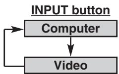
INPUT MENU
text_image
Input Computer Video SVGA 1 INPUT Menu icon Move the red arrow to Computer and press the SET button.SELECTING THE COMPUTER SYSTEM
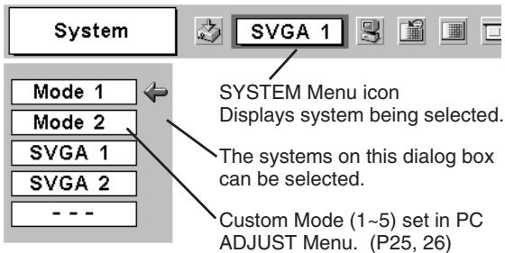
This projector automatically tunes to most different types of computers based on VGA, SVGA, XGA or SXGA (refer to "COMPATIBLE COMPUTER SPECIFICATION" on page 23). When selecting Computer, this projector automatically tunes to incoming signal and projects proper image without any special setting. (Some computers need to be set manually.)
Note : Projector may display one of the following messages.
Auto
When the projector cannot recognize the connected signal, the Auto PC Adjustment function adjusts the projector and the message “Auto” is displayed on the SYSTEM Menu icon. (Refer to P24.) When the image is not displayed properly, manual adjustment is required. (Refer to P25 and 26.)
—
There is no signal input from the computer. Make sure the connection between the computer and the projector are set correctly.
(Refer to TROUBLESHOOTING on page 40.)
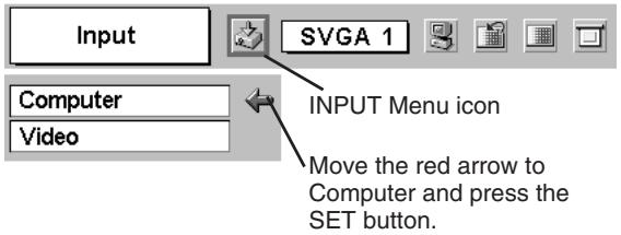
SELECT THE COMPUTER SYSTEM MANUALLY
This projector automatically selects the PC system among those provided in this projector and PC system can be also selected manually.
1 Press the MENU button and the ON-SCREEN MENU will appear. Press the POINT LEFT/RIGHT buttons to move the red frame to PC SYSTEM Menu icon.
2 Press the POINT DOWN button to move the red arrow to the system that you want to set, and then press the SET button.
PC SYSTEM MENU
text_image
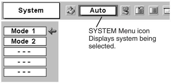
System Mode 1 Mode 2 - - - - - - Auto SYSTEM Menu icon Displays system being selected.PC SYSTEM MENU
text_image
System SVGA 1 Mode 1 Mode 2 SVGA 1 SVGA 2 --- SYSTEM Menu icon Displays system being selected. The systems on this dialog box can be selected. Custom Mode (1~5) set in PC ADJUST Menu. (P25, 26)COMPATIBLE COMPUTER SPECIFICATIONS
This projector can accept the signal from all computers with the V, H-Frequency below mentioned and less than 140 MHz of Dot Clock.
| ON-SCREEN DISPLAY | RESOLUTION | H-Freq. (kHz) | V-Freq. (Hz) | ON-SCREEN DISPLAY | RESOLUTION | H-Freq. (kHz) | V-Freq. (Hz) |
| VGA 1 | 640 x 480 | 31.47 | 59.88 | XGA 11 | 1024 x 768 | 61.00 | 75.70 |
| VGA 2 | 720 x 400 | 31.47 | 70.09 | XGA 12 | 1024 x 768 | 35.522 | 86.96 (Interlace) |
| VGA 3 | 640 x 400 | 31.47 | 70.09 | XGA 13 | 1024 x 768 | 46.90 | 58.20 |
| VGA 4 | 640 x 480 | 37.86 | 74.38 | XGA 14 | 1024 x 768 | 47.00 | 58.30 |
| VGA 5 | 640 x 480 | 37.86 | 72.81 | XGA 15 | 1024 x 768 | 58.03 | 72.00 |
| VGA 6 | 640 x 480 | 37.50 | 75.00 | MAC 19 | 1024 x 768 | 60.24 | 75.08 |
| VGA 7 | 640 x 480 | 43.269 | 85.00 | MAC 21 | 1152 x 870 | 68.68 | 75.06 |
| MAC LC13 | 640 x 480 | 34.97 | 66.60 | SXGA 1 | 1152 x 864 | 64.20 | 70.40 |
| MAC 13 | 640 x 480 | 35.00 | 66.67 | SXGA 2 | 1280 x 1024 | 62.50 | 58.60 |
| RGB | —— | 15.625 | ^50 (Interlace) | SXGA 3 | 1280 x 1024 | 63.90 | 60.00 |
| RGB | —— | 15.734 | ^60 (Interlace) | SXGA 4 | 1280 x 1024 | 63.34 | 59.98 |
| SVGA 1 | 800 x 600 | 35.156 | 56.25 | SXGA 5 | 1280 x 1024 | 63.74 | 60.01 |
| SVGA 2 | 800 x 600 | 37.88 | 60.32 | SXGA 6 | 1280 x 1024 | 71.69 | 67.19 |
| SVGA 3 | 800 x 600 | 46.875 | 75.00 | SXGA 7 | 1280 x 1024 | 81.13 | 76.107 |
| SVGA 4 | 800 x 600 | 53.674 | 85.06 | SXGA 8 | 1280 x 1024 | 63.98 | 60.02 |
| SVGA 5 | 800 x 600 | 48.08 | 72.19 | SXGA 9 | 1280 x 1024 | 79.976 | 75.025 |
| SVGA 6 | 800 x 600 | 37.90 | 61.03 | SXGA 10 | 1280 x 960 | 60.00 | 60.00 |
| SVGA 7 | 800 x 600 | 34.50 | 55.38 | SXGA 11 | 1152 x 900 | 61.20 | 65.20 |
| SVGA 8 | 800 x 600 | 38.00 | 60.51 | SXGA 12 | 1152 x 900 | 71.40 | 75.60 |
| SVGA 9 | 800 x 600 | 38.60 | 60.31 | SXGA 13 | 1280 x 1024 | 50.00 | 86.00 (Interlace) |
| SVGA 10 | 800 x 600 | 32.70 | 51.09 | SXGA 14 | 1280 x 1024 | 50.00 | 94.00 (Interlace) |
| SVGA 11 | 800 x 600 | 38.00 | 60.51 | SXGA 15 | 1280 x 1024 | 63.37 | 60.01 |
| MAC 16 | 832 x 624 | 49.72 | 74.55 | SXGA 16 | 1280 x 1024 | 76.97 | 72.00 |
| XGA 1 | 1024 x 768 | 48.36 | 60.00 | SXGA 17 | 1152 x 900 | 61.85 | 66.00 |
| XGA 2 | 1024 x 768 | 68.677 | 84.997 | SXGA 18 | 1280 x 1024 | 46.43 | 86.70 (Interlace) |
| XGA 3 | 1024 x 768 | 60.023 | 75.03 | SXGA 19 | 1280 x 1024 | 63.79 | 60.18 |
| XGA 4 | 1024 x 768 | 56.476 | 70.07 | MAC | 1280 x 960 | 75.00 | 75.08 |
| XGA 5 | 1024 x 768 | 60.31 | 74.92 | MAC | 1280 x 1024 | 80.00 | 75.08 |
| XGA 6 | 1024 x 768 | 48.50 | 60.02 | 720p (HDTV) | —— | 45.00 | 60.00 |
| XGA 7 | 1024 x 768 | 44.00 | 54.58 | 1035i (HDTV) | —— | 33.75 | 60.00 (Interlace) |
| XGA 8 | 1024 x 768 | 63.48 | 79.35 | 1080i 60(HDTV) | —— | 33.75 | 60.00 (Interlace) |
| XGA 9 | 1024 x 768 | 36.00 | ^87.17 (Interlace) | 1080i 50(HDTV) | —— | 28.125 | 50.00 (Interlace) |
| XGA 10 | 1024 x 768 | 62.04 | 77.07 | ||||
NOTE : Specifications are subject to change without notice.
PC ADJUSTMENT
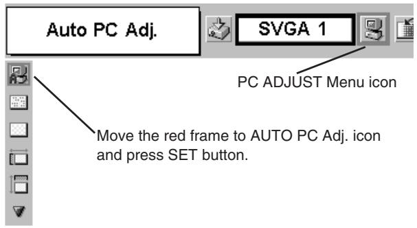
AUTO PC ADJUSTMENT
The Auto PC Adjustment function is provided to automatically adjust Fine sync, Total dots and Picture Position to conform to your computer. Auto PC Adjustment function can be operated as follows.

Auto PC Adj.
1 Press the MENU button and the ON-SCREEN MENU will appear. Press POINT LEFT/RIGHT button to move the red frame to PC ADJUST Menu icon.
2 Press the POINT DOWN button to move the red frame to the AUTO PC Adj. icon and then press the SET button twice. This Auto PC Adjustment can be also executed by pressing the AUTO PC ADJ. button on the Remote Control Unit.
Store adjustment parameters.
Adjustment parameters from Auto PC Adjustment can be memorized in this projector. Once parameters are memorized, setting can be done just by selecting Mode in PC SYSTEM Menu (P22). Refer to step 3 of MANUAL PC ADJUSTMENT section (P26).
NOTE
- Fine sync, Total dots and Picture Position of some computers can not be fully adjusted with this Auto PC Adjustment function. When the image is not provided properly through this function, manual adjustments are required. (Refer to page 25, 26.)
- Auto PC Adjustment function cannot be operated when “RGB,” “720p (HDTV),” “1035i (HDTV)” or “1080i (HDTV)” is selected on PC SYSTEM Menu (P22).
PC ADJUST MENU
text_image
Auto PC Adj. SVGA 1 PC ADJUST Menu icon Move the red frame to AUTO PC Adj. icon and press SET button.MANUAL PC ADJUSTMENT
This projector can automatically tune to the display signals of most personal computers. However, some computers employ special signal formats which are different from the standard ones and may not be tuned by the Multi-Scan system of this projector. If this happens, projector cannot reproduce a proper image and the image may be displayed as a flickering picture, a non-synchronized picture, a non-centered picture or a skewed picture.
This projector has Manual PC Adjustment to enable you to precisely adjust several parameters to match those special signal formats. This projector has 5 independent memory areas to memorize those parameters manually adjusted. This enables you to recall the setting for a specific computer whenever you use it.
Note : This PC ADJUST Menu cannot be operated when "RGB" is selected on PC SYSTEM Menu (P22).
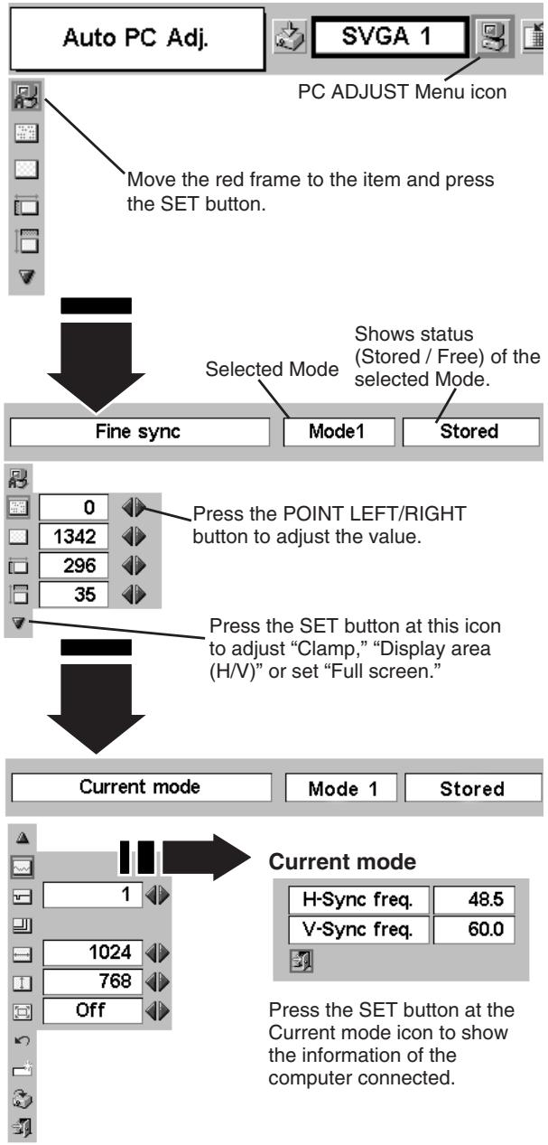
1 Press the MENU button and the ON-SCREEN MENU will appear. Press the POINT LEFT/RIGHT button to move the red frame to PC ADJUST Menu icon.
2 Press the POINT DOWN button to move the red frame to the item that you want to adjust and then press the SET button. The Adjustment dialog box will appear. Press the POINT LEFT/RIGHT button to adjust value.

Fine sync
Adjusts an image as necessary to eliminate flicker from the display. Press the POINT LEFT/RIGHT button to adjust value.(From 0 to 31.)

Total dots
The number of total horizontal dots in your picture. Press the POINT LEFT/RIGHT button(s) and adjust number to match your PC image.

Horizontal
Adjusts the horizontal picture position. Press the POINT LEFT/RIGHT button(s) to adjust the position.

Vertical
Adjusts the vertical picture position. Press the POINT LEFT/RIGHT button(s) to adjust the position.

Current mode
Press the SET button to show the information of the computer selected.

Clamp
Adjusts the clamp level. When the image has a dark bar(s), try this adjustment.
PC ADJUST MENU
flowchart
graph TD
    A["PC ADJUST Menu icon"] --> B["Move the red frame to the item and press the SET button."]
    B --> C["Selected Mode"]
    C --> D["Fine sync"]
    C --> E["Mode1"]
    C --> F["Stored"]
    G["Press the POINT LEFT/RIGHT button to adjust the value."] --> H["Press the SET button at this icon to adjust "Clamp," "Display area (H/V)" or set "Full screen.""]
    I["Press the SET button at this icon to adjust "Clamp," "Display area (H/V)" or set "Full screen.""] --> J["Press the SET button at this icon to adjust "Clamp," "Display area (H/V)" or set "Full screen.""]
    K["Current mode"] --> L["Mode 1"]
    K --> M["Stored"]
    N["Current mode"] --> O["H-Sync freq. 48.5"]
    N --> P["V-Sync freq. 60.0"]
    Q["Press the SET button at the Current mode icon to show the information of the computer connected."] --> R["Press the SET button at the Current mode icon to show the information of the computer connected."]

Display area
Selects the area displayed with this projector. Select the resolution at the Display area dialog box.

Display area H
Adjustment of horizontal area displayed with this projector. Press the POINT LEFT/RIGHT button(s) to decrease/increase value to match the resolution of image.

Display area V
Adjustment of vertical area displayed with this projector. Press the POINT LEFT/RIGHT button(s) to decrease/increase value to match the resolution of image.

Full screen
Press the POINT LEFT/RIGHT button(s) to switch Full screen function to “On” or “Off.” Set “On” to resize the image with 4 x 3 aspect ratio to fit the screen.
NOTE : Display area (H/V) and Full screen cannot be adjusted when "1035i (HDTV)" or "1080i (HDTV)" is selected on PC SYSTEM Menu (P22).
3

Store
To store adjustment parameters, move the red frame to the Store icon and then press the SET button. Move the red arrow to any of Mode 1 to 5 that you want to store and then press the SET button.

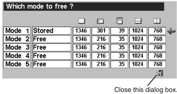
Mode free
To clear the adjustment parameters previously set, move the red frame to Mode free icon and then press the SET button. Move the red arrow to the Mode that you want to clear and then press the SET button.
Other icons operate as follows.

Reset
Reset all adjustment parameters on the adjustment dialog box to the previous figure.

Quit
Closes PC ADJUST MENU.
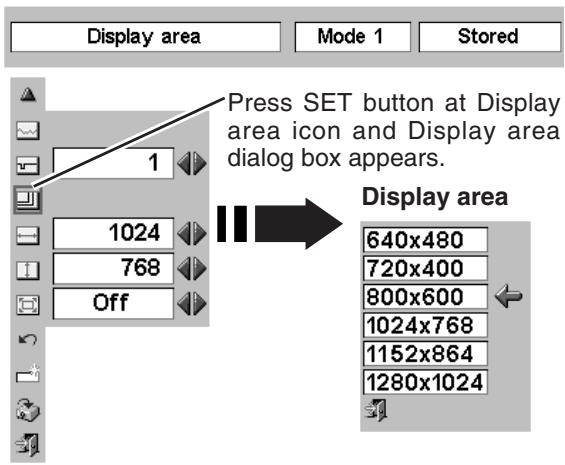
text_image
Display area Mode 1 Stored Press SET button at Display area icon and Display area dialog box appears. Display area 640x480 720x400 800x600 1024x768 1152x864 1280x1024To store the adjustment data.
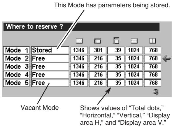
text_image
This Mode has parameters being stored. Where to reserve ? Mode 1 Stored 1346 301 39 1024 768 Mode 2 Free 1346 216 35 1024 768 Mode 3 Free 1346 216 35 1024 768 Mode 4 Free 1346 216 35 1024 768 Mode 5 Free 1346 216 35 1024 768 Vacant Mode Shows values of "Total dots," "Horizontal," "Vertical," "Display area H," and "Display area V."To clear the adjustment data.
text_image
Which mode to free ? Mode 1 Stored 1346 301 39 1024 768 Mode 2 Free 1346 216 35 1024 768 Mode 3 Free 1346 216 35 1024 768 Mode 4 Free 1346 216 35 1024 768 Mode 5 Free 1346 216 35 1024 768 Close this dialog box.PICTURE IMAGE ADJUSTMENT
IMAGE LEVEL SELECT (DIRECT)
Select the image level among Standard, High contrast and Custom by pressing the IMAGE button on the Remote Control Unit.
Standard
Normal picture adjustment preset on this projector.
High contrast
Picture adjustment improved in reproduction of halftones. This adjustment is suitable for providing better image in brighter place.
Custom
User preset picture adjustment in the IMAGE ADJUST Menu (P28, 29).
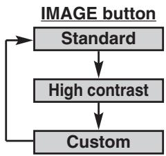
flowchart
graph TD
    A["IMAGE button"] --> B["Standard"]
    B --> C["High contrast"]
    C --> D["Custom"]
    D --> B
IMAGE LEVEL SELECT (MENU)
1 Press the MENU button and the ON-SCREEN MENU will appear. Press the POINT LEFT/RIGHT button to move the red frame to the IMAGE SELECT Menu icon.
2 Press the POINT DOWN button to move the red frame to the level that you want to set and then press the SET button.

Standard
Normal picture adjustment preset on this projector.

High contrast
Picture adjustment improved in reproduction of halftones. This adjustment is suitable for providing better image in brighter place.

Custom
User preset picture adjustment in the IMAGE ADJUST Menu (P28, 29).
IMAGE SELECT MENU
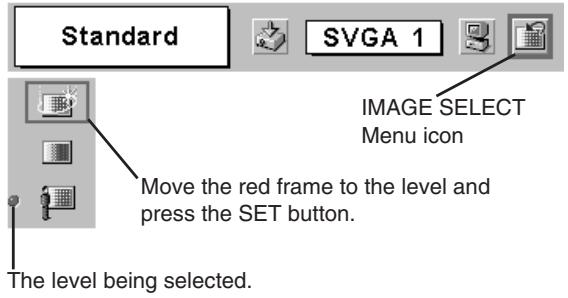
text_image
Standard SVGA 1 IMAGE SELECT Menu icon Move the red frame to the level and press the SET button. The level being selected.IMAGE LEVEL ADJUSTMENT
1 Press the MENU button and the ON-SCREEN MENU will appear. Press the POINT LEFT/RIGHT buttons to move the red frame to the IMAGE ADJUST Menu icon.
2 Press the POINT DOWN button to move the red frame to the item that you want to adjust. and then press the SET button. The level of each item is displayed. Adjust each level by the pressing the POINT LEFT/RIGHT button(s).

Contrast
Press the POINT LEFT button to decrease contrast, and the POINT RIGHT button to increase contrast. (From 0 to 63.)

Brightness
Press the POINT LEFT button to adjust image darker, and the POINT RIGHT button to adjust brighter. (From 0 to 63.)

Color
Press the POINT LEFT button to lighten color, and the POINT RIGHT button to darker color. (From 0 to 63.)

Tint
Press the POINT LEFT button or the POINT RIGHT button to obtain proper color. (From 0 to 63.)

White balance (Red)
Press the POINT LEFT button to lighten red tone and the POINT RIGHT button to darker tone. (From 0 to 63.)

White balance (Green)
Press the POINT LEFT button to lighten green tone and the POINT RIGHT button to darker tone. (From 0 to 63.)

White balance (Blue)
Press the POINT LEFT button to lighten blue tone and the POINT RIGHT button to darker tone. (From 0 to 63.)

Sharpness
Press the POINT LEFT button to soften the image, and the POINT RIGHT button to sharpen the image. (From 0 to 15.)

Gamma
Press either the POINT LEFT button or the POINT RIGHT button to obtain better balance of contrast. (From 0 to 15.)

Auto grayscale
When this function is "ON", it automatically enhances the contrast of the bright and dark part of image.

Auto fleshtone
When this function is "ON", it automatically produces a more vivid image according to the image condition.
IMAGE ADJUST MENU
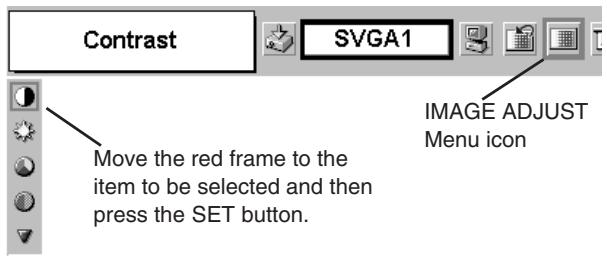
text_image
Contrast SVGA1 MOVE the red frame to the item to be selected and then press the SET button. IMAGE ADJUST Menu icon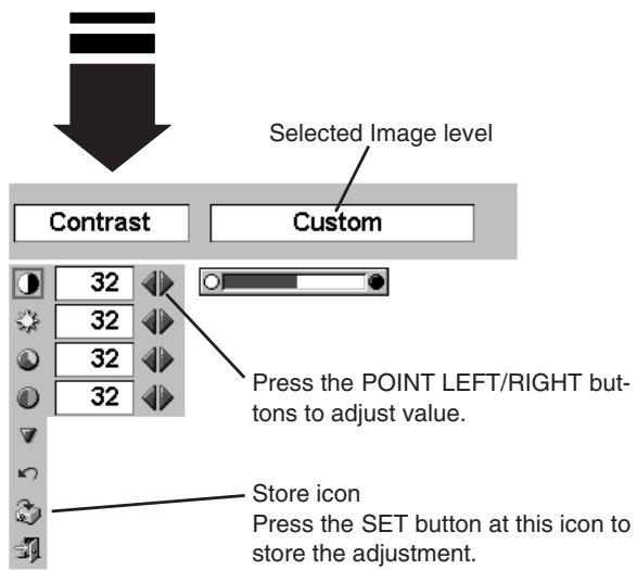
text_image
Selected Image level Contrast Custom 32 32 32 32 Press the POINT LEFT/RIGHT buttons to adjust value. Store icon Press the SET button at this icon to store the adjustment.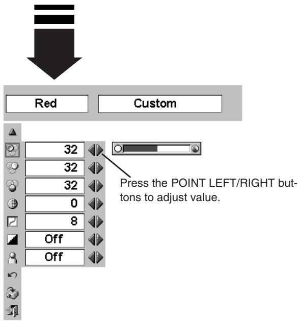
text_image
Red Custom 32 32 32 0 8 Off Off Press the POINT LEFT/RIGHT buttons to adjust value.3

Store
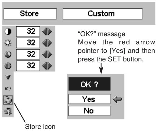
To store the manually preset image level, move the red frame to the Store icon and press the SET button. The message "OK?" will appear. Select [Yes] to store the manual adjustment.
To set this manual adjustment, select the Custom by pressing the IMAGE button or through the IMAGE SELECT MENU (refer to P27).
Other icons operate as follows.

Reset
Reset all adjustment to previous figure.

Quit
Closes the IMAGE MENU.
text_image
Store 32 32 32 32 Store icon Custom "OK?" message Move the red arrow pointer to [Yes] and then press the SET button. OK ? Yes NoPICTURE SCREEN ADJUSTMENT
This projector has a picture screen resize function, which enables you to display the desirable image size.
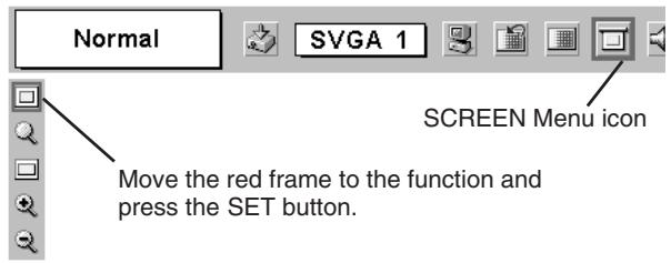
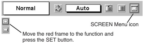
1 Press the MENU button and the ON-SCREEN MENU will appear. Press the POINT LEFT/RIGHT button(s) to move the red frame to the SCREEN Menu icon.
2 Press the POINT DOWN button and move the red frame to the function that you want to select and then press the SET button.

Normal
Provides image to fit screen size.

True
Provides image in its original size. When the original image size is larger than screen size (1024 x 768), this projector enters “Digital zoom +” mode automatically.

Wide
Provides an image to fit the wide video aspect ratio (16 : 9) by expanding image width uniformly. This function can be used for providing a squeezed video signal at 16 : 9.

Digital zoom +
When Digital zoom + is selected, the ON-SCREEN MENU disappears and the message "D. Zoom +" is displayed. Press the SET button to expand image size. And press the POINT UP/DOWN/LEFT/RIGHT button(s) to pan the image. The panning function can work only when the image is larger than screen size. A projected image can be also expanded by pressing D.ZOOM W (Wide) button on Remote Control Unit.

Digital zoom –
When Digital zoom – is selected, the ON-SCREEN MENU disappears and the message "D. Zoom –" is displayed. Press the SET button to compress image size.
A projected image can be also compressed by pressing the D.ZOOM T (Tele) button on Remote Control Unit.
To cancel the Digital Zoom +/- mode, press any button except D.ZOOM W/T, SET, and POINT buttons.
SCREEN MENU
text_image
Normal SVGA 1 SCREEN Menu icon Move the red frame to the function and press the SET button.NOTE
- This SCREEN Menu cannot be operated when "1035i (HDTV)" or "1080i (HDTV)" is selected on PC SYSTEM Menu (P22).
- Wide cannot be selected when "720p (HDTV)" is selected on PC SYSTEM Menu (P22).
- True and Digital zoom +/- cannot be selected when “RGB” is selected on PC SYSTEM Menu (P22).
- This projector cannot display any resolution higher than 1280 X 1024. If your computer's screen resolution is higher than 1280 X 1024, lower the resolution before connecting projector.
- Digital zoom – cannot be operated when the image resolution is SXGA (1280 x 1024).
● The image data in other than XGA (1024 x 768) is modified to fit the screen size. - The panning function may not operate properly if the computer system set on PC ADJUST Menu is used.
SELECTING THE INPUT SOURCE
DIRECT OPERATION
Choose Video by pressing the INPUT button on the Top Control or on the Remote Control Unit.
If the projector cannot reproduce a proper video source, select correct input source through the MENU OPERATION (see below).
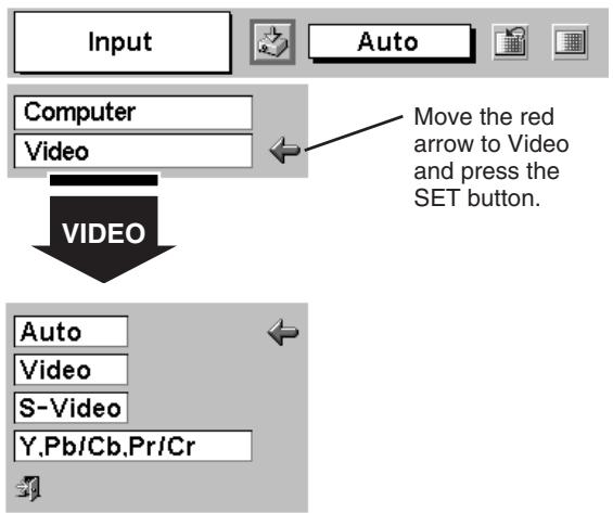
MENU OPERATION
1 Press the MENU button and the ON-SCREEN MENU will appear. Press the POINT LEFT/RIGHT button to move the red frame to the INPUT Menu icon.
2 Press the POINT DOWN button to move the red arrow to Video and then press the SET button. The Source Select Menu will appear.
3 Move the red arrow to the source that you want to select and then press the SET button.
Auto
The projector automatically detects incoming the Video signal, and adjusts itself to optimize its performance.
- When both VIDEO jack and S-VIDEO jack are connected, S-VIDEO jack has priority over VIDEO jack.
- When both Y-Pb/Cb-Pr/Cr jacks and S-VIDEO jack are connected, Y-Pb/Cb-Pr/Cr jacks have priority over S-VIDEO jack.
Video
When the video input signal is connected to VIDEO jack, select Video.
S-Video
When the video input signal is connected to S-VIDEO jack, select S-Video.
Y,Pb/Cb,Pr/Cr
When the video input signal is connected to Y-Pb/Cb-Pr/Cr jacks, select Y, Pb/Cb, Pr/Cr.
INPUT MENU
text_image
Input Auto Computer Video MOVE the red arrow to Video and press the SET button. VIDEO Auto Video S-Video Y,Pb/Cb,Pr/CrSource Select Menu (VIDEO)
Move the red arrow to the source and press the SET button.
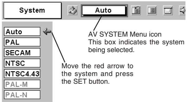
SELECTING THE VIDEO SYSTEM
1 Press the MENU button and the ON-SCREEN MENU will appear. Press the POINT LEFT/RIGHT buttons to move the red frame to AV SYSTEM Menu icon.
2 Press the POINT DOWN button to move the red arrow to the system that you want to select and then press the SET button.
VIDEO JACK OR S-VIDEO JACK
Auto
Projector automatically detects the incoming Video system, and adjusts itself to optimize its performance. When Video System is PAL-M or PAL-N, select system manually.
PAL / SECAM / NTSC / NTSC4.43 / PAL-M / PAL-N
If projector cannot reproduce a proper video image, it is necessary to select a specific broadcast signal format among PAL, SECAM, NTSC, NTSC 4.43, PAL-M, and PAL-N.
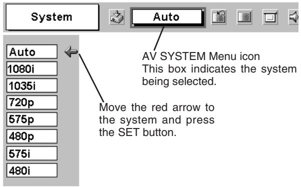
Y, Pb/Cb, Pr/Cr JACKS
Auto
The projector automatically detects the incoming Video signal, and then adjusts itself to optimize its performance.
COMPONENT VIDEO SIGNAL FORMAT
If the projector cannot reproduce a proper video image, it is necessary to select a specific component video signal format among 480i, 575i, 480p, 575p, 720p, 1035i and 1080i.
AV SYSTEM MENU (VIDEO OR S-VIDEO)
text_image
System Auto AV SYSTEM Menu icon This box indicates the system being selected. Move the red arrow to the system and press the SET button.AV SYSTEM MENU (COMPONENT VIDEO)
text_image
System Auto AV SYSTEM Menu icon This box indicates the system being selected. Move the red arrow to the system and press the SET button.PICTURE IMAGE ADJUSTMENT
IMAGE LEVEL SELECT (DIRECT)
Select the image level among Standard, Cinema, and Custom by pressing the IMAGE button on Remote Control Unit.
Standard
Normal picture adjustment preset on this projector.
Cinema
Picture level adjusted for the picture with fine tone.
Custom
User preset picture adjustment in IMAGE ADJUST Menu (P33,34).
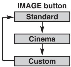
flowchart
graph TD
    A["IMAGE button"] --> B["Standard"]
    B --> C["Cinema"]
    C --> D["Custom"]
    D --> B
IMAGE LEVEL SELECT (MENU)
1 Press the MENU button and the ON-SCREEN MENU will appear. Press the POINT LEFT/RIGHT button to move the red frame to the IMAGE SELECT Menu icon.
2 Press the POINT DOWN button to move the red frame to the level that you want to set and then press the SET button.

Standard
Normal picture adjustment preset on this projector.

Cinema
Picture level adjusted for the picture with fine tone.

Custom
User preset picture adjustment in IMAGE ADJUST Menu (P33, 34).
IMAGE SELECT MENU
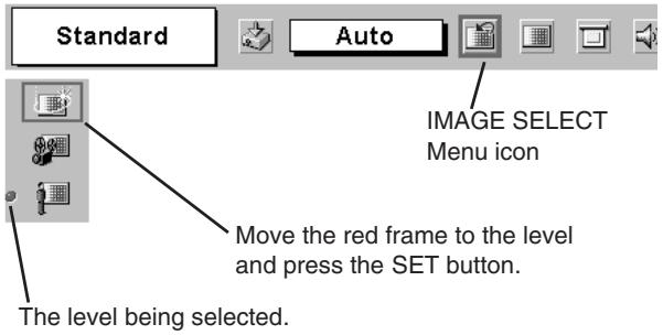
text_image
Standard Auto IMAGE SELECT Menu icon Move the red frame to the level and press the SET button. The level being selected.IMAGE LEVEL ADJUSTMENT
1 Press the MENU button and the ON-SCREEN MENU will appear. Press the POINT LEFT/RIGHT button(s) to move the red frame to the IMAGE ADJUST Menu icon.
2 Press the POINT DOWN button to move the red frame to the item that you want to adjust and then press the SET button. The level of each item is displayed. Adjust each level by pressing the POINT LEFT/RIGHT button(s).

Contrast
Press the POINT LEFT button to decrease contrast, and the POINT RIGHT button to increase contrast. (From 0 to 63.)

Brightness
Press the POINT LEFT button to adjust image darker, and the POINT RIGHT button to adjust brighter. (From 0 to 63.)

Color
Press the POINT LEFT button to lighten color, and the POINT RIGHT button to darker color. (From 0 to 63.)

Tint
Press the POINT LEFT button or the POINT RIGHT button to obtain the proper color. (From 0 to 63.)

White balance (Red)
Press the POINT LEFT button to lighten the red tone and the POINT RIGHT button to darker tone. (From 0 to 63.)

White balance (Green)
Press the POINT LEFT button to lighten the green tone and the POINT RIGHT button to darker tone. (From 0 to 63.)

White balance (Blue)
Press the POINT LEFT button to lighten the blue tone and the POINT RIGHT button to darker tone. (From 0 to 63.)

Sharpness
Press the POINT LEFT button to soften the image, and the POINT RIGHT button to sharpen the image. (From 0 to 15.)

Gamma
Press either the POINT LEFT button or the POINT RIGHT button to obtain a better balance of contrast. (From 0 to 15.)

Auto grayscale
When this function is "ON", it automatically enhances the contrast of the bright and dark part of image.

Auto fleshtone
When this function is "ON", it produces a more vivid image according to the image condition.
IMAGE ADJUST MENU
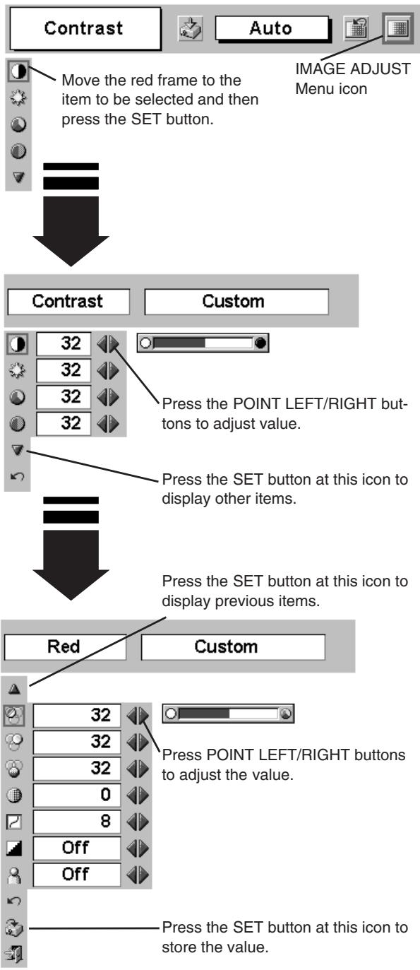
flowchart
graph TD
    A["Move the red frame to the item to be selected and then press the SET button."] --> B["IMAGE ADJUST Menu icon"]
    B --> C["Press SET button at this icon to display previous items."]
    C --> D["Press SET button at this icon to store the value."]
NOTE : Tint cannot be adjusted when the video system is PAL, SECAM, PAL-M or PAL-N.
3

Store
To store a manually preset image level, move the red frame to the Store icon and press the SET button. The message "OK?" will appear. Select [Yes] to store the manual adjustment. To set this manual adjustment, select Custom by pressing the IMAGE button or through the IMAGE SELECT MENU (refer to P32).
Other icons operate as follows.

Reset
Reset all adjustment to the previous figure.

Quit
Closes the IMAGE MENU.
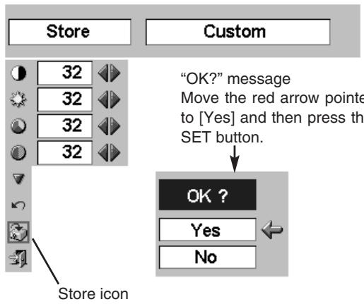
text_image
Store Custom 32 32 32 32 "OK?" message Move the red arrow pointed to [Yes] and then press the SET button. OK ? Yes No Store iconPICTURE SCREEN ADJUSTMENT
This projector has a picture screen resize function, which enables you to display the desirable image size.
1 Press the MENU button and the ON-SCREEN MENU will appear. Press the POINT LEFT/RIGHT button(s) to move the red frame to the SCREEN Menu icon.
2 Press the POINT DOWN button and move the red frame to the function that you want to select and then press the SET button.

Normal
Provides image at a normal video aspect ratio of 4 : 3.
SCREEN MENU
text_image
Normal Auto SCREEN Menu icon Move the red frame to the function and press the SET button.
Wide
Provides image at a wide screen ratio of 16 : 9.
NOTE : The SCREEN Menu cannot be operated when “720p,” “1035i,” or “1080i” is selected on the AV SYSTEM Menu (P31).
SETTING MENU
1 Press the MENU button and the ON-SCREEN MENU will appear. Press the POINT LEFT/RIGHT button(s) to move the red frame to the SETTING icon.
2 Press the POINT DOWN button to move the red frame to the item that you want to set and then press the SET button. The Setting dialog box appears.

Language
The Language used in the ON-SCREEN MENU is selectable from English, German, French, Italian, Spanish, Portuguese, Dutch, Swedish, Chinese, Korean, and Japanese.

Keystone
When the image is distorted vertically, select Keystone. The ONSCREEN MENU disappears and the Keystone dialog box is displayed. Correct the keystone distortion by pressing the POINT UP/DOWN button(s). Refer to KEYSTONE ADJUSTMENT on page 20.

Blue back
When this function is “On,” the projector produces a blue image while the input signal is not detected.

Display
This function decides whether to display the On-Screen Displays.
On … shows all the On-Screen Displays.
Off .... sets On-Screen Displays disappeared except;
● ON-SCREEN MENU
● “Power off?” message (P19)
● P-TIMER
● “No signal” message (P36)
● "Wait a moment!" message

Logo
When this function is “On,” the projector displays the Canon logo when starting up.

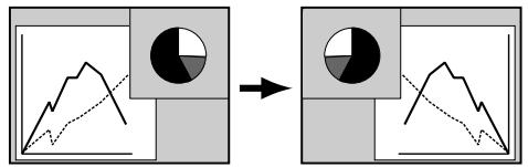
Ceiling
When this function is “On,” the picture is top / bottom and left / right reversed. This function is used to project the image from a ceiling mounted projector.

Rear
When this function is “On,” picture is left / right reversed. This function is used to project the image to a rear projection screen.
SETTING MENU
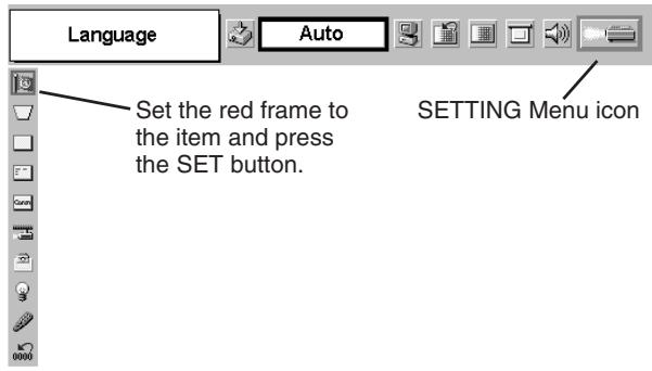
text_image
Language Auto Set the red frame to the item and press the SET button. SETTING Menu icon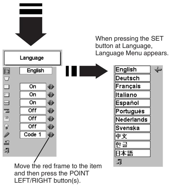
flowchart
graph TD
    A["Language"] --> B["English"]
    B --> C["On"]
    C --> D["On"]
    D --> E["On"]
    E --> F["Off"]
    F --> G["Off"]
    G --> H["Code 1"]
    I["When pressing the SET button at Language, Language Menu appears."] --> J["English"]
    J --> K["Deutsch"]
    J --> L["Français"]
    J --> M["Italiano"]
    J --> N["Espanol"]
    J --> O["Portugues"]
    J --> P["Nederlands"]
    J --> Q["Svenska"]
    J --> R["中文"]
    J --> S["한글"]
    J --> T["日本語"]
    U["Move the red frame to the item and then press the POINT LEFT/RIGHT button(s)."] --> V
Ceiling function
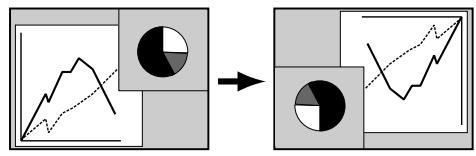
flowchart
graph LR
    A["Line Graph"] --> B["Pie Chart"]
    style A fill:#f9f,stroke:#333
    style B fill:#bbf,stroke:#333
Rear function
flowchart
graph TD
    A["Graph with solid black circle"] --> B["Circular graph with solid black circle"]
    C["Graph with dashed black line"] --> D["Circular graph with dashed black line"]

Power management
This function turns the Projection Lamp off when this projector detects signal interruption and is not used for a certain period in order to reduce power consumption and maintain the Lamp-life. (This projector is shipped with this function ON.)
Power Management function operates to turn the Projection Lamp off when the input signal is interrupted and any button is not pressed over 5 minutes. This function operates as follows;
- When any input signal is interrupted, "No signal" and the count down display appears (for 5 minutes).
- After counting down for 5 minutes, the Projection Lamp and the READY Indicator are turned off. (Cooling Fans keep running.)
- The READY Indicator starts to flash after cooling down the Projection Lamp about for 90 seconds (Power Management mode).
In this Power Management mode, the Projection Lamp is automatically turned on when the input signal is connected or the projector is operated with any button on the Top Control or on the Remote Control Unit again.

Remote control
This projector has two different remote control codes; the factory-set normal code (Code 1) and the secondary code (Code 2). This switching function prevents remote control interference when operating several projectors or video equipment together.
When operating projector in “Code 2,” both projector and Remote Control Unit must be switched to “Code 2.”
To change the code of Projector;
Set the Remote control in the SETTING MENU to "Code 2."
To change the code of the Remote Control Unit;
Press both the MENU and the IMAGE buttons on the Remote Control Unit together for over 10 seconds.
After changing the code, make sure the Remote Control Unit operates properly.
To return to the normal code (Code 1), repeat the steps above.
NOTE : When the battery of Remote Control Unit is replaced, the remote control code automatically returns to the normal code (Code 1).

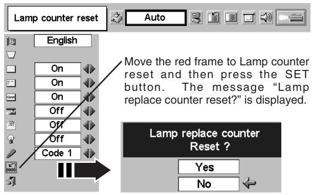
Lamp counter reset
This function is used to reset the Lamp Replace Counter. When replacing the Projection Lamp, reset the Lamp Replace Counter by using this function. Refer to page 38 for operation.
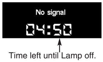
text_image
No signal 04:50 Time left until Lamp off.LAMP REPLACEMENT
LAMP REPLACE
When the life of the Projection Lamp of this projector draws to an end, the LAMP REPLACE indicator lights yellow. If this indicator lights yellow, replace the projection lamp with a new one promptly.
TOP CONTROL
This indicator lights yellow when the life of the projection lamp draws to an end. Replace the Projection Lamp with a new one promptly.
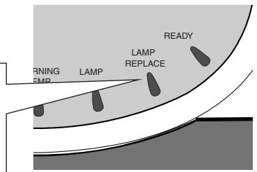
text_image
WARNING FMP LAMP LAMP REPLACE READY
Allow the projector to cool, for at least 45 minutes before you open the Lamp Cover. The inside of a projector can become very hot.

CAUTION
For continued safety, replace with a lamp assembly of the same type.
Do not drop the lamp assembly or touch the glass bulb! The glass can shatter and may cause injury.
Follow these steps to replace the lamp assembly.
1 Turn off the projector and disconnect the AC plug. Allow the projector to cool at least for 45 minutes.
2 To remove the Lamp Cover, remove the screw with a screwdriver.
3 Remove the 2 screws with a screwdriver and pull out Lamp Assembly by grasping Handle.
4 Replace the Lamp Assembly with a new one and tighten 2 screws back into position. Make sure that the Lamp Assembly is set properly. Replace Lamp Cover and tighten the screw.
5 Connect the AC Power Cord to the projector and turn on the projector.
6 Reset the Lamp Replace Counter.
Refer to "LAMP REPLACE COUNTER" on the next page.
NOTE: Do not reset the Lamp Replace Counter when Projection Lamp is not replaced.
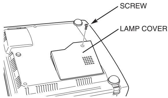
text_image
SCREW LAMP COVER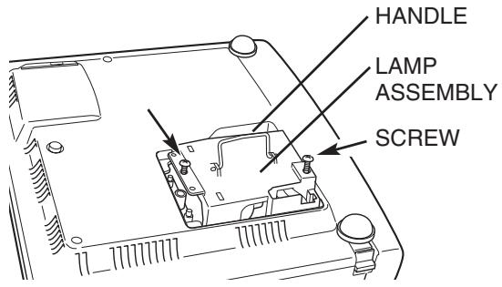
text_image
HANDLE LAMP ASSEMBLY SCREWORDER REPLACEMENT LAMP
The Replacement Lamp can be ordered through your dealer. When ordering a Projection Lamp, give the following information to the dealer.
● Model No. of your projector : LV-X2
● Replacement Lamp Type No. : LV-LP15
(Service Parts No. 610 300 7267)
LAMP REPLACE COUNTER
Be sure to reset the Lamp Replace Counter after the Lamp Assembly is replaced. When the Lamp Replace Counter is reset, the LAMP REPLACE Indicator stops lighting.
1 Turn the projector on, press the MENU button and the ONSCREEN MENU will appear. Press the POINT LEFT/RIGHT button(s) to move the red frame to the SETTING Menu icon (refer to page 35, 36).
2 Press the POINT DOWN button to move the red frame to "Lamp counter reset" and then press the SET button. The message "Lamp replace counter reset?" is displayed. Move the red arrow to [Yes] and then press the SET button.
3 Another confirmation dialog box appears and select [Yes] to reset the Lamp Replace Counter.
text_image
Lamp counter reset Auto English On On On Off Off Off Code 1 Move the red frame to Lamp counter reset and then press the SET button. The message "Lamp replace counter reset?" is displayed. Lamp replace counter Reset ? Yes NoNOTE : Do not reset the Lamp Replace Counter until after the Projection Lamp is replaced.

LAMP HANDLING PRECAUTIONS
This projector uses a high-pressure lamp which must be handled carefully and properly. Improper handling may result in accidents, injury, or create a fire hazard.
- Lamp lifetime may differ from lamp to lamp and according to the environment of use. There is no guarantee of the same lifetime for each lamp. Some lamps may fail or terminate their lifetime in a shorter period of time than other similar lamps.
- If the projector indicates that the lamp should be replaced, i.e., if the LAMP REPLACE INDICATOR lights up, replace the lamp with a new one IMMEDIATELY after the projector has cooled down. (Follow carefully the instructions in the LAMP REPLACEMENT section of this manual.) Continuous use of the lamp with the LAMP REPLACE INDICATOR lighted may increase the risk of lamp explosion.
● A Lamp may explode as a result of vibration, shock or degradation as a result of hours of use as its lifetime draws to an end. Risk of explosion may differ according to the environment or conditions in which the projector and lamp are being used.
IF A LAMP EXPLODES, THE FOLLOWING SAFETY PRECAUTIONS SHOULD BE TAKEN.
If a lamp explodes, disconnect the projector's AC plug from the AC outlet immediately. Contact an authorized service station for a checkup of the unit and replacement of the lamp. Additionally, check carefully to ensure that there are no broken shards or pieces of glass around the projector or coming out from the cooling air circulation holes. Any broken shards found should be cleaned up carefully. No one should check the inside of the projector except those who are authorized trained technicians and who are familiar with projector service. Inappropriate attempts to service the unit by anyone, especially those who are not appropriately trained to do so, may result in an accident or injury caused by pieces of broken glass.
MAINTENANCE
WARNING TEMP. INDICATOR
The WARNING TEMP. Indicator flashes red when the internal temperature of the projector exceeds the normal temperature. This Indicator stops flashing when the temperature of the projector returns to normal.
When the WARNING TEMP. Indicator continues to flash, check the items listed below.
1 The Ventilation Slots of the projector may be blocked. In such an event, reposition the projector so that the Ventilation Slots are not obstructed.
2 The Air Filter may be clogged with dust particles. Clean the Air Filter by following section AIR FILTER CARE AND CLEANING below.
3 If the WARNING TEMP. Indicator remains on after performing the above checks, the Cooling Fans or the Internal Circuits may be malfunctioning. Contact service personnel from an authorized dealer or a service station.
AIR FILTER CARE AND CLEANING
The Removable Air Filter prevents dust from accumulating on the surface of the Projection Lens and the Projection Mirror. Should the Air Filter become clogged with dust particles, it will reduce Cooling Fans' effectiveness and may result in internal heat build up and adversely affect the life of the projector. Clean Air Filter following the steps below:
1 Turn off the projector, and disconnect the AC power cord from the AC outlet.
2 Turn the projector upside down and remove the two Air Filters (Large and Small) by pulling the latches upward.
3 Clean the Air Filters with a brush or wash out dust and particles.
4 Replace each Air Filter properly. Make sure that the Air Filters are fully inserted.

CAUTION
Do not operate the projector with the Air Filter removed. Dust may accumulate on the LCD Panel and the Projection Mirror, therefore degrading picture quality.
Do not put small parts into Air Intake Vents. It may result in malfunction of the projector.
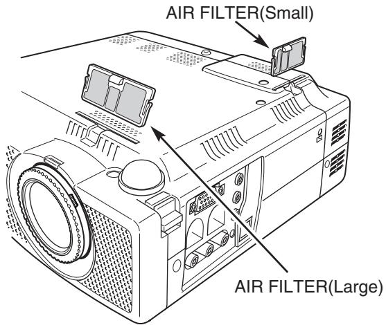
text_image
AIR FILTER(Small) AIR FILTER(Large)RECOMMENDATION
We recommend avoiding dusty/smoky environment when operating a projector. Usage in these environments may cause poor image quality.
When using under dusty or smoky conditions, dust may accumulate on the lens, liquid crystal panels, or optical elements inside the projector. This condition may degrade the quality of a projected image.
When the above symptoms are noticed, contact your authorized dealer or service station for proper cleaning.
CLEANING PROJECTION LENS
Follow these steps to clean the Projection Lens:
1 Apply a non-abrasive camera lens cleaner to a soft, dry cleaning cloth. Avoid using an excessive amount of cleaner. Abrasive cleaners, solvents or other harsh chemicals might scratch the lens.
2 Lightly wipe a cleaning cloth over Projection Lens.
3 When the projector is not in use, attach Lens Cover.
TROUBLESHOOTING
Before calling your dealer or service center for assistance, check the following:
- Make sure you have connected a projector to your computer or video equipment as described in the section "CONNECTING THE PROJECTOR" on pages 11 \~ 13.
- Check cable connection. Verify that all computer, video and power cord are properly connected.
- Verify that all power is switched on.
- If a projector still does not produce an image, re-start your computer.
- If an image still does not appear, unplug the projector from your computer and check your computer monitor's display. The problem may be with your graphics controller rather than with the projector. (When you reconnect the projector, be sure to turn the computer and monitor off before you power up the projector. Turn the projector on, and then the computer.)
- If the problem still exists, check the following chart.
| Problem: | Try these Solutions |
| No power. | Plug the projector into your AC outlet.Make sure the READY Indicator lights.Wait 90 seconds after a projector is turned OFF before turning the projector back on.NOTE : After pressing the Power ON-OFF button to OFF, make sure the projector works as follows:LAMP indicator lights bright and READY indicator turns off.After 90 seconds, the READY indicator lights green again and the projector may be turned on by pressing the Power ON-OFF button.Check WARNING TEMP. indicator. If the indicator flashes red, the projector cannot be turned on.(See "TURNING ON/OFF PROJECTOR" section on page 19.)Check Projection Lamp. (Refer to page 37.) |
| Image is out of focus. | Adjust focus of the projector.Make sure the projection screen is at least 3.6' (1.1m) from the projector.Check Projection Lens to see if it needs cleaning.NOTE : Moving a projector from a cool temperature location to a warm temperature location may result in moisture condensation on the Projection Lens. In such an event, leave the projector OFF and wait until condensation disappears. |
| Picture is Left/Right reversed. | Check Ceiling / Rear feature. (See “SETTING” section on page 35.) |
| Picture is Top/Bottom reversed. | Check Ceiling feature. (See “SETTING” section on page 35.) |
| Some displays are not seen during the Operation. | Check Display feature.(See “SETTING” section on page 35.) |
| No image. | Check the connection between your computer or video equipment and the projector.Check the NO SHOW function. (Refer to page 21.)When turning the projector on, it takes about 30 seconds to display an image.Check the system that you select is corresponding with your computer or video equipment.Make sure the temperature is not out of the Operating Temperature (5°C ~ 35°C). |
| No sound. | Check audio cable connection from the audio input source.Adjust the audio source.Press the VOLUME (+) button.Press the MUTE button. |
| Remote Control Unit does not work. | ● Check the battery.● Make sure nothing is between the Infrared Remote Receiver and the Remote Control Unit.● Observe maximum operating distance 16.4’ (5m) between the receiver on the projector and the Remote Control Unit.● Make sure the code of the Remote Control Unit is set to conform to the projector.(See “SETTING” section on page 35, 36.) |
WARNING :
High voltages are used to operate this projector. Do not attempt to open the cabinet.
If the problem still persists after following all operating instructions, contact the sales dealer where you purchased the projector or the service center. Give the model number and explain the problem in detail. We will advise you of how to obtain service.

text_image
C UL US LISTEDThis symbol on the nameplate means the product is Listed by Underwriters Laboratories Inc. It is designed and manufactured to meet rigid U.L. safety standards against risk of fire, casualty and electrical hazards.

The CE Mark is a Directive conformity mark of the European Community. (EC)
TECHNICAL SPECIFICATIONS
| Projector Type | Multi-media Projector |
| Dimensions (W x H x D) | 10.24" x 2.99" x 9.63" (260mm x 76mm x 244.5mm) (not including Adjustable Feet) |
| Net Weight | 6.39lbs (2.9 kg) |
| LCD Panel System | 0.7" TFT Active Matrix type, 3 panels |
| Panel Resolution | 1024 x 768 dots |
| Number of Pixels | 2,359,296 (1024 x 768 x 3 panels) |
| Color System | PAL, SECAM, NTSC, NTSC4.43, PAL-M and PAL-N |
| High Definition TV Signal | 480i, 480p, 575i, 575p, 720p, 1035i, and 1080i |
| Scanning Frequency | H-sync. 15 ~ 100 KHz, V-sync. 50 ~ 100 Hz |
| Projection Image size (Diagonal) | Adjustable from 29" to 200" |
| Horizontal Resolution | 550 TV lines (S-Video) |
| Projection Lens | F 1.6 ~ 2.0 lens with f 20.3 mm ~ 28.2 mm with manual zoom and focus |
| Throw Distance | 3.6' ~ 26.2' (1.1 m ~ 8 m) |
| Projection Lamp | 132 W |
| Video Input Jacks | RCA Type x 3 (Video/Y, Pb/Cb, Pr/Cr) and Mini DIN 4 pin x 1 (S-Video) |
| Audio Input Jacks | Mini Jack (stereo) x 1 |
| Computer Input Terminals | (VGA) HDB 15 Terminal x 1 |
| Computer Audio Input Jack | Mini Jack (stereo) x 1 |
| Control Port Connector | Mini DIN 8 pin x 1 |
| USB Connector | USB Series B receptacle x 1 |
| Audio Output Jacks | Mini Jack (stereo) x 1 |
| Internal Audio Amp | 1.0 W RMS |
| Built-in Speaker | 1 speaker, 1.4" x 0.8" (35mm x 20mm) |
| Feet Adjustment | 0° to 10.7° |
| Voltage and Power Consumption | AC 100 ~ 120 V (2.5 A Max. Ampere), 50 / 60 Hz (The U.S.A and Canada)AC 200 ~ 240 V (1.4 A Max. Ampere), 50 / 60 Hz (Continental Europe) |
| Operating Temperature | 41 °F ~ 95 °F (5 °C ~ 35 °C) |
| Storage Temperature | 14 °F ~ 140 °F (-10 °C ~ 60 °C) |
| Remote Control Unit | Power Source : Lithium Type (CR2025 / 3.0V)Operating Range : 16.4' (5m) / ±30°Dimensions : 2.1" x 0.28" x 5.3" (54mm x 7mm x 135mm)Net Weight : 1.27oz (36 g) (including battery) |
| Accessories | Owner's ManualAC Power CordRemote Control Unit and BatteryVGA CableCarrying BagLens Cover |
● The specifications are subject to change without notice.
OPTIONAL PARTS
The parts listed below are optionally supplied. When ordering those parts, give name and Type No. of it to the sales dealer.
● Wireless Remote Control Unit Type No.: LV-RC01
● Control Cable for PS/2Port Type No.: LV-CA25
● Control Cable for Serial Port Type No.: LV-CA26
● Control Cable for ADB Port
● MAC Adapter
● Ceiling Mount Hanger
Type No.: LV-CA27
Type No.: LV-AD02
Type No.: LV-CL06
CONFIGURATIONS OF THE TERMINALS
COMPUTER INPUT TERMINAL (ANALOG)
Terminal : HDB15-PIN
Connect the display output terminal of the computer to this terminal with the VGA Cable (supplied). When connecting the Macintosh computer, MAC Adapter (not supplied) is required.
Pin Configuration
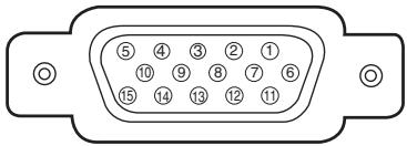
text_image
⑤ ④ ③ ② ① ⑩ ⑨ ⑧ ⑦ ⑥ ⑮ ⑭ ⑬ ⑭| 1 | Red Input | 9 | No Connect |
| 2 | Green Input | 10 | Ground (Vert.sync.) |
| 3 | Blue Input | 11 | Sense 0 |
| 4 | Sense 2 | 12 | Sense 1 |
| 5 | Ground (Horiz.sync.) | 13 | Horiz. sync. |
| 6 | Ground (Red) | 14 | Vert. sync. |
| 7 | Ground (Green) | 15 | Reserved |
| 8 | Ground (Blue) | ||
CONTROL PORT CONNECTOR
Terminal : Mini DIN 8-PIN
Connect control port (PS/2, Serial or ADB port) on your computer to this connector with Control Cable (not supplied).
Pin Configuration
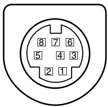
text_image
8 7 6 5 4 3 2 1| PS/2 | Serial | ADB | |
| 1 | ---- | R X D | ---- |
| 2 | CLK | ---- | ADB |
| 3 | DATA | ---- | ---- |
| 4 | GND | GND | GND |
| 5 | ---- | RTS / CTS | ---- |
| 6 | ---- | T X D | ---- |
| 7 | GND | GND | ---- |
| 8 | ---- | GND | GND |
USB CONNECTOR (Series B)
Connect USB port terminal on your computer or peripheral equipment to this connector with USB Cable (not supplied).
Pin Configuration
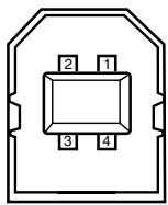
| 1 | Vcc |
| 2 | - Data |
| 3 | + Data |
| 4 | Ground |
Canon
CANON INC. 30-2, Shimomaruko 3-chome, Ohta-ku, Tokyo 146-8501, Japan
CANON U.S.A., INC.
One Canon Plaza, Lake Success, NY 11042, U.S.A.
CANON CANADA, INC.
6390 Dixie Road Mississauga, Ontario L5T 1P7 Canada
CANON LATIN AMERICA, INC.
703 Waterford Way Suite 400 Miami, Florida 33126 U.S.A.
CANON EUROPA N.V.
P.O.Box 2262, 1180 EG Amstelveen, The Netherlands
CANON COMMUNICATION & IMAGE FRANCE S.A.
102, Avenue du General de Gaulle, 92250 La Garenne Colombes, France
CANON (UK) LTD.
Woodhatch, Reigate, Surrey RH2 8BF, United Kingdom
CANON DEUTSCHLAND GmbH
Europark Fichtenhain A 10, 47807 Krefeld, Germany
CANON ITALIA S.p.A.
Palazzo L, Strada 6, 20089 Milanofiori-Rozzano (MI), Italy
CANON (Schweiz) A.G.
Industriestrasse 12, 8305 Dietlikon, Switzerland
CANON BENELUX N.V.
Neptunusstraat 1, 2132 JA Hoofddorp, The Netherlands
CANON BENELUX N.V./S.A.
Bessenveldstraat 7, 1831 Diegem (Machelen), Belgium
CANON GmbH
Zetschegasse 11, A-1232 Wien, Austria
CANON ESPANA S.A.
C/Joquin Costa 41, 28002 Madrid, Spain
CANON SVENSKA AB
Stensätravägen 13, S-127 88 Skarholmen 2, Sweden
CANON NORGE A/S
Hallagerbakken 110, P. O. Box 2-33, Holmlia 1201 Oslo 12, Norway
CANON OY
Kornetintie 3, 00381 Helsinki, Finland
CANON HONGKONG CO., LTD.
9/F, The Hong Kong Club Building, 3A Chater Road, Central, Hong Kong
CANON SINGPORE PTE. LTD.
79 Anson Road #09-01/06, Singapore 079906
CANON AUSTRALIA PTY. LTD.
1 Thomas Holt Drive, North Ryde, Sydney, N.S.W.2113, Australia
CANON NEW ZEALAND LTD.
Suite 4, 2nd Floor, Asda Plaza, Fred Thomas Drive, P.O.Box 33-336, Takapuna, Auckland, New Zealand