DUO 240 - Détecteur de mouvement VISONIC - Notice d'utilisation et mode d'emploi gratuit
Retrouvez gratuitement la notice de l'appareil DUO 240 VISONIC au format PDF.
| Type de produit | Détecteur de mouvement double technologie (infrarouge et micro-ondes) |
| Marque | VISONIC |
| Modèle | DUO 240 |
| Dimensions (H x Ø) | 24 x 86 mm |
| Poids | 64 g |
| Alimentation | 9-16 VDC (nominal 12 VDC), consommation 30 mA |
| Fonctions principales | Détection par double technologie (PIR et micro-ondes) avec algorithme True Motion Recognition™ ; autotest périodique par simulateur de mouvement micro-ondes ; choix du compteur d'événements PIR (1 ou 2) ; portée de détection jusqu'à 10,8 m de diamètre (hauteur de plafond 4,5 m) ; réglage de la portée micro-ondes ; indicateurs LED vert et rouge ; sortie relais NC ; sortie défaut ; contact d'autoprotection. |
| Entretien et nettoyage | Vérifier le fonctionnement au moins deux fois par an. Nettoyer avec un chiffon doux et sec. Éviter les produits abrasifs ou solvants. |
| Sécurité | Conforme EN 50131-1 Grade 2 Classe II et UL-639. Dispositif d'autoprotection (tamper) contre l'ouverture du boîtier. Sortie défaut en cas de dysfonctionnement. |
| Pièces détachées et réparabilité | Aucune pièce détachable accessible à l'utilisateur. En cas de défaut, remplacer l'unité complète. Contacter le fabricant ou un installateur agréé. |
| Informations générales | Température de fonctionnement : -10°C à 50°C ; température de stockage : -20°C à 60°C ; protection RFI > 30 V/m (20-1000 MHz) ; fréquence micro-ondes : 2,45 GHz ; montage au plafond jusqu'à 4,5 m de hauteur. |
FOIRE AUX QUESTIONS - DUO 240 VISONIC
Questions des utilisateurs sur DUO 240 VISONIC
0 question sur cet appareil. Repondez a celles que vous connaissez ou posez la votre.
Poser une nouvelle question sur cet appareil
Téléchargez la notice de votre Détecteur de mouvement au format PDF gratuitement ! Retrouvez votre notice DUO 240 - VISONIC et reprennez votre appareil électronique en main. Sur cette page sont publiés tous les documents nécessaires à l'utilisation de votre appareil DUO 240 de la marque VISONIC.
MODE D'EMPLOI DUO 240 VISONIC
1. INTRODUCTION
DUO 240 is a microcomputer-controlled, ceiling-mounted dual-technology intrusion detector. Its operation is based on two physical phenomena - the infrared (IR) radiation emitted by the human body and the Doppler frequency shift caused by a person moving in a microwave (MW) field. The IR and MW technologies, when combined in a single detector, complement each other to assure the most reliable detection and immunity to false alarms.
The superiority of the DUO 240 over other dual detectors has been achieved by the advent of a True Motion Recognition™
algorithm (patented). This advanced motion analysis method provides the DUO 240 with the ability to distinguish between the true motion of a human body and any other disturbances which invariably cause false alarms.
Another unique feature of the DUO 240 is the MW Motion Simulator circuit (patents applied for), which simulates the effect created by a human body moving in the MW field. The simulation routine is carried out periodically for self-testing, supervision and assurance that the MW detector operates properly.
2. SPECIFICATIONS
Input Voltage: 9 to 16 VDC (Nominal: 12 VDC)
Current Drain: About 30 mA @ 12 VDC
PIR SECTION
Detector: Low noise dual-element pyroelectric sensor
Trip Indication: Green LED flashes for up to 5 seconds
True Motion Event Verification Counter: 1 or 2 events
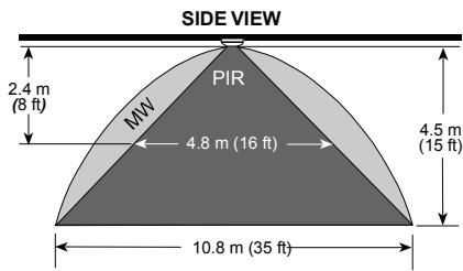
Detection Pattern: A virtually conical pattern of maximum 10.8 m (35 ft) diameter, when installed on a 4.5 m (15 ft) ceiling (Fig. 1).
Mounting on a lower ceiling will reduce the coverage area.
MW SECTION
Oscillator: Microstrip DRO-stabilized type
Frequency: 2.45 GHz
Detection Range: Adjustable from 25% to 100%
Trip Indication: Green LED lights for up to 5 seconds
ALARM, TAMPER & TROUBLE DATA
Alarm Indication: Red LED lights for 2-3 s (both detectors trip)
Relay Contacts: Normally closed, 0.1 A resistive/30 VDC; 18 Ω resistor in series with contacts
Alarm Duration: 2-3 seconds (red LED lights and output relay contacts open)
Tamper Contacts: Normally closed, 50 mA resistive/ 30 VDC
Trouble Output: Open-collector, 100mA max., with 47 resistor in series
MOUNTING AND PHYSICAL DATA
Maximum Mounting Height: 4.5m (15 ft)
Dimensions (H x Ø): 24 x 86 mm (3.4 x 0.95 in.)
Weight: 64 g (2 oz)
Color: White
TOP VIEW

Figure 1. DUO 240 Coverage Pattern
ENVIRONMENTAL CONDITIONS
Operating Temperature: -10^ to 50^ (14°F to 122°F)
Storage Temperature: -20^ to 60^ (-4^ to 140^)
RFI Protection: Greater than 30V / m (20 to 1000 MHz)
PATENTS
U.S. Patents 5,237,330 and 5,693,943 (other patents pending)
Compliance with standards: EN 50131-1 Grade 2 Class II, UL-639
ATTENTION! Detection occurs only in areas in which the MW and PIR patterns overlap.
3. INSTALLATION
3.1 General Guidelines
A few important rules must be observed before selecting a mounting location.
- Microwave radiation passes through glass and nonmetallic walls and floors. Be sure to adjust the MW range to the necessary minimum, to reduce the possibility of interference from lower floors.
- Large reflecting objects (especially metals) within the coverage area can distort the microwave detector's coverage pattern.
- Although the DUO 240 is extremely immune to air turbulence and RF interference, avoid installation in a room with very
strong air drafts or close to high-power electrical cables. It is also recommended to avoid aiming the detection pattern at sources of bright light and/or heat.
- If two DUO 240 units are installed in the same room, they should be mounted at least 2m (6 ft) apart.
- Always mount the unit on a firm and stable ceiling and remember that the height above the floor determines the size of the circular coverage pattern.
- Do not install the DUO 240 in places where one of the two detectors alarms constantly or intermittently, due to environmental interference.
3.2 Mounting
Select the mounting location in accordance with the guidelines in Section 3.1. Make sure that the expected intruder's path will cross the detector's coverage pattern. DUO 240 units can be mounted at the maximum height of 4.5m (15 ft). Proceed as follows:
A. Hold the base with one hand as shown in Fig. 2. Twist the cover counterclockwise with the other hand until it stops. Separate the cover from
the base, and put it in a safe place, to avoid accidental damage.
B. Press the base against the ceiling in the selected location. Mark the two points for drilling through the mounting holes (see Fig. 3).
a safe place, to avoid accidental
B. Press the base against the ceiling in the selected location. Mark the two points for drilling through the mounting holes (see Fig. 3).
Note: The mounting holes are accessible without removing the printed circuit board from the base. Do not drill with the detector held in place, to avoid contaminating the unit with dust and drilled fragments.
C. Put the base aside, drill the two holes in the ceiling and insert masonry anchors if necessary.
D. Punch out at least one wiring knockout (preferably the one close to the terminal block).
E. Align the unit (including printed circuit board) with the mounting holes and fasten it firmly to the ceiling with two screws.
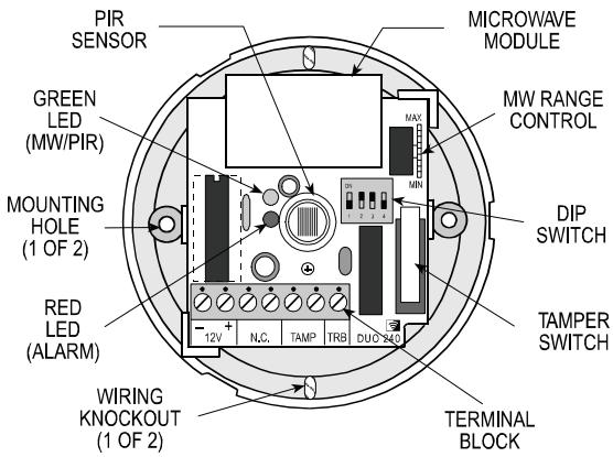
Figure 3. Component Layout
3.3 Wiring
Connect wires to the terminal block in the following order (Fig. 4):
Terminal: TAMP (tamper switch)
Connect to: A normally closed 24-hour tamper zone of the control panel.
Details: Once the cover is removed, the tamper switch opens.

Figure 2. Separating the Cover from the Base
Terminal: NC (alarm relay)
Connect to: Normally closed burglar protection zones of the control panel.
Details: Upon alarm or power failure, the output relay's normally closed contacts open.
Terminal: TRB (trouble output)
Connect to: 24-hour trouble zone, parallel to an E.O.L. resistor (see Figure 4).
Details: The TRB open collector output will be grounded upon detector malfunction, causing disturbance in the trouble zone of the associated alarm system.
Alternative: A buzzer or an interface relay (100 mA max.) may be connected across the TRB output and the 12 V (+) terminals.
In UL installations, the buzzer, control panel or relay to which the trouble output is connected must be UL-listed.
Terminals: 12V(+) and (-)
Connect to: A power source within the range of 9 VDC to 16 VDC. Take care not to reverse the polarity.
Details: It is advisable to connect the power source only after all other connections have been completed and rechecked. Disconnect the AC mains from the alarm control panel and verify that the voltage supplied to the detector is above 9 Volts with the backup battery as the only power source.
IMPORTANT: To comply with CE safety requirements, connect to CE-approved control panels with current-limited DC output.
Note: Use RTV to seal the base opening(s) to prevent insects from entering the detector.
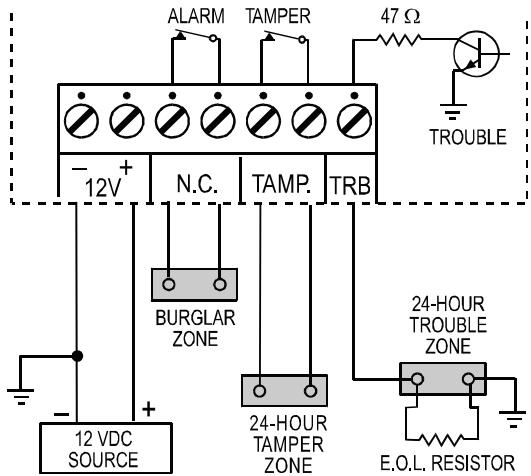
Figure 4. Terminal Block Wiring
3.4 The Power-up Process
After connecting the (+) and (-) terminals to the power source, the DUO 240 starts a 60-second warm-up period, indicated by alternate flashing of the green and red LEDs.
Caution! If the alternate flashing of the LEDs does not stop within 60 seconds, a failure has been detected by the self-test circuitry and the TRB output is activated
4. INDICATORS AND SELECTORS
4.1 LED Indications
The two LEDs (Fig. 3), which are hidden behind the lens when the cover is installed, are visible through the lens when illuminated. They are used to signal various alarm and trouble messages as shown in Table 1 below:
Notes:
- During walk testing, the first LED to respond is the green one. It illuminates steadily (MW detection) or flashes (PIR detection), depending on which detector discovered the movement first. Upon subsequent discovery of the movement by the other detector, the green LED will go off and the red LED will illuminate (alarm).
- If the green and red LEDs continue to flash beyond the warm-up period, a malfunction has been diagnosed. Replace the unit without delay.
Table 1. Interpreting the States of the LEDs
| GREEN | RED | Significance |
| Off | Off | No detection |
| On | Off | MW walk-test detection |
| Flashes | Off | PIR walk-test detection |
| Off | On | Alarm: MW + PIR detection |
| Flashes | Flashes | Trouble is being detected by the self test circuitry, or Initial warm-up routine (stops 60 seconds after power up). |
4.2 Mode Selector
The DIP switch mode selector is mounted on the unit's PC board (Fig. 3). It controls four functions as demonstrated in Fig. 5 and as detailed in Table 2.
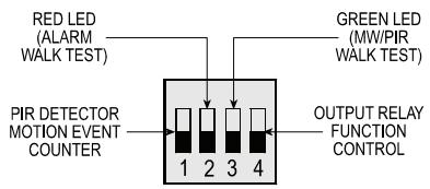
Figure 5. DIP Switch Mode Selector
Table 2. Mode Selector Switch Functions
| Switch | State | Function | Default |
| SW-1 | OFF | One motion event trips the PIR | ON |
| ON | Two motion events trip the PIR | ||
| SW-2 | OFF | Alarm walk test is disabled* | ON |
| ON | Alarm walk test is enabled | ||
| SW-3 | OFF | MW/PIR walk test is disabled* | ON |
| ON | MW/PIR walk test is enabled | ||
| SW-4 | OFF | Output relay opens upon alarm | OFF |
| ON | Output relay opens upon alarm and when trouble is detected. |
- Setting SW-2 and SW-3 to OFF does not disable the trouble indication (flash/flash).
5. INITIAL ADJUSTMENT
5.1 Setting the Motion Event Counter
If you wish to set the PIR detector for maximum false alarm immunity, shift DIP switch No. 1 (SW-1) to ON. In this position, two consecutive motion events are required to trip the PIR detector.
For faster catch performance, shift SW-1 to OFF. In this position, only one motion event is required to trip the PIR detector.
5.2 PIR Walk Test
A. Rotate the MW RANGE control all the way toward MIN.
B. Verify that DIP switch SW-3 is set to ON (the green walk-test LED is enabled).
C. Mount the front cover in place: line up the ridge on the cover with the cavity in one of the two projections on the base circumference (Fig 6). Fit the cover over the base, and rotate the cover clockwise until it stops.
D. Walk into the detector's field of view at the expected far edge of the coverage area. The green LED should flash for up to 5 seconds each time your motion is detected.
E. If PIR detection is not obtained at the far edge of the coverage area, verify that the infrared radiation is not blocked or diverted by intervening objects such as large lampshades, air conditioning ducts etc.
Note: If the green LED illuminates steadily, your motion has been detected by the MW detector and not by the PIR.
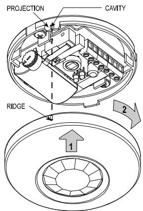
Figure 6. Remounting the Cover
6. WARNINGS
Although this detector is a highly reliable device, it does not guarantee complete protection against intrusion. Even the most sophisticated detectors can sometimes be defeated or may fail to warn because:
A. The detector will not function if the DC power supplied to it is incorrect or improperly connected.
5.3 MW Walk Test
A. Remove the front cover.
B. Verify that the MW range control is set to MIN and that DIP switch SW-3 is set to ON (the green walk-test LED is enabled). Close cover (see section 5.2 C).
C. Start by moving into the coverage area at the far edge. The green LED should light steadily for up to 5 seconds each time your motion is detected.
D. If your motion was not detected at the far edge of the coverage area, advance the MW RANGE control slightly toward MAX and try again until your motion is detected reliably at the far edge.
Caution! The MW detection range must not exceed the far edge of the desired coverage area.
E. Walk across the coverage area at various ranges and verify that your motion is consistently detected.
Note: If PIR trips interfere with your test, disable the PIR by inserting a small piece of cardboard in front of the sensor.
5.4 Alarm Walk Test
A. Set DIP switches SW-2 and SW-3 to ON (both LEDs are enabled).
B. Temporarily mount the detector's cover in place.
C. Walk across the detector's field of view in different directions, at various distances from the detector, and verify proper detection throughout the entire coverage area (the red LED will illuminate for 2 to 3 seconds).
D. When done, remove the cover and set DIP switches SW-2 and SW-3 to OFF to prevent unauthorized people from tracing the coverage pattern.
E. Remount the cover.
Attention! To assure proper function of the detector, the range and coverage area should be checked at least twice a year. Furthermore, it is recommended to perform a walk test at the far end of the coverage pattern to assure an alarm signal prior to each time the alarm system is armed.
B. Detection is confined to the area covered by the detection pattern as adjusted by the installer.
C. A PIR detector does not provide full volumetric coverage of the protected area. It can only detect motion that disturbs the sensitive beam array spread within the protected space.
D. Motion will not be detected by PIRs if it takes place behind closed doors, floors, walls, ceilings, glass partitions, windows and shutters.
E. The detection ability of the PIR detector may be reduced by malicious masking or by spraying various materials on the optical lens. Mechanical tampering may also damage the optical system.
F. The PIR detector's performance can decrease as the ambient temperature within the protected area approaches the range of 32^ - 40^ ( 90^ - 105^ ).
G. The protection pattern provided by the microwave detector may be altered by metal objects or foil-covered insulation.
H. Even the most reliable electrical devices, including this detector, may go wrong because of unexpected failure of component parts.
The above list includes the most common reasons for failure to detect intrusion, but it is by no means comprehensive. It is therefore recommended that the detector and the entire alarm system be checked weekly, to ensure proper performance.
An alarm system should not be regarded as a substitute for insurance. Home and property owners or renters should be prudent enough to continue insuring their lives and property, even though they are being protected by an alarm system.
This device complies with Part 15 of the FCC Rules and RSS-210 of Industry and Science Canada. Operation is subject to the following two conditions: (1) This device may not cause harmful interference, and (2) this device must accept any interference received, including interference that may cause undesired operation.
This device complies with the essential requirements and provisions of Directive 1999/5/EC of the European Parliament and of the Council of 9 March 1999 on radio and telecommunications terminal equipment.
Note: The manufacturer is not responsible for any radio or TV interference caused by unauthorized modifications to this equipment. Such modifications could void the user's authority to operate the equipment.
WARRANTY
Visonic Limited (the "Manufacturer") warrants this product only (the "Product") to the original purchaser only (the "Purchaser") against defective workmanship and materials under normal use of the Product for a period of twelve (12) months from the date of shipment by the Manufacturer.
This Warranty is absolutely conditional upon the Product having been properly installed, maintained and operated under conditions of normal use in accordance with the Manufacturers recommended installation and operation instructions. Products which have become defective for any other reason, according to the Manufacturers discretion, such as improper installation, failure to follow recommended installation and operational instructions, neglect, willful damage, misuse or vandalism, accidental damage, alteration or tampering, or repair by anyone other than the manufacturer, are not covered by this Warranty.
The Manufacturer does not represent that this Product may not be compromised and/or circumvented or that the Product will prevent any death and/or personal injury and/or damage to property resulting from burglary, robbery, fire or otherwise, or that the Product will in all cases provide adequate warning or protection. The Product, properly installed and maintained, only reduces the risk of such events without warning and it is not a guarantee or insurance that such events will not occur.
THIS WARRANTY IS EXCLUSIVE AND EXPRESSLY IN LIEU OF ALL OTHER WARRANTY, OBLIGATIONS OR LIABILITIES, WHETHER WRITTEN, ORAL, EXPRESS OR IMplied, INCLUDING ANY WARRANTY OF MERCHANTABILITY OR FITNESS FOR A PARTICULAR PURPOSE, OR OTHERWISE. IN NO CASE SHALL THE MANUFACTURER BE LIABLE TO ANYONE FOR ANY CONSEJCTUAL OR INCIDENTAL DAMAGES FOR BREACH OF THIS WARRANTY OR ANY OTHER WARRANTYMENTS whatsoever, AS FORESAAID.
THE MANUFACTURER SHALL IN NO EVENT BE LIABLE FOR ANY SPECIAL, INDIRECT, INCIDENTAL, CONSEQUENTIAL OR PUNITIVE DAMAGES OR FOR LOSS, DAMAGE, OR EXPENSE, INCLUDING LOSS OF USE, PROFITS, REVENUE, OR GOODWILL, DIRECTLY OR INDIRECTLY ARISING FROM PURCHASER'S USE OR INABILITY TO USE THE PRODUCT, OR FOR LOSS OR DESTRUCTION OF OTHER PROPERTY OR FROM ANY OTHER CAUSE, EVEN IF MANUFACTURER HAS BEEN ADVISED OF THE POSSIBILITY OF SUCH DAMAGE.
THE MANUFACTURER SHALL HAVE NO LIABILITY FOR ANY DEATH, PERSONAL AND/OR BODILY INJURY AND/OR DAMAGE TO PROPERTY OR OTHER LOSS WHETHER DIRECT, INDIRECT, INCIDENTAL, CONSEQUENTIAL OR OTHERWISE, BASED ON A CLAIM THAT THE PRODUCT Failed TO FUNCTION.
However, if the Manufacturer is held liable, whether directly or indirectly, for any loss or damage arising under this limited warranty, THE MANUFACTURER'S MAXIMUM LIABILITY (IF ANY) SHALL NOT IN ANY CASE EXCEED THE PURCHASE PRICE OF THE PRODUCT, which shall be fixed as liquidated damages and not as a penalty, and shall be the complete and exclusive remedy against the Manufacturer.
When accepting the delivery of the Product, the Purchaser agrees to the said conditions of sale and warranty and he recognizes having been informed of.
Some jurisdictions do not allow the exclusion or limitation of incidental or consequential damages, so these limitations may not apply under certain circumstances.
The Manufacturer shall be under no liability whatsoever arising out of the corruption and/or malfunctioning of any telecommunication or electronic equipment or any programs.
The Manufacturers obligations under this Warranty are limited solely to repair and/or replace at the Manufacturer's discretion any Product or part thereof that may prove defective. Any repair and/or replacement shall not extend the original Warranty period. The Manufacturer shall not be responsible for dismantling and/or reinstatement costs. To exercise this Warranty the Product must be returned to the Manufacturer freight prepaid and insured. All freight and insurance costs are the responsibility of the Purchaser and are not included in this Warranty.
This warranty shall not be modified, varied or extended, and the Manufacturer does not authorize any person to act on its behalf in the modification, variation or extension of this warranty. This warranty shall apply to the Product only. All products, accessories or attachments of others used in conjunction with the Product, including batteries, shall be covered solely by their own warranty, if any. The Manufacturer shall not be liable for any damage or loss whatsoever, whether directly, indirectly, incidentally, consequentially or otherwise, caused by the malfunction of the Product due to products, accessories, or attachments of others, including batteries, used in conjunction with the Products. This Warranty is exclusive to the original Purchaser and is not assignable.
This Warranty is in addition to and does not affect your legal rights. Any provision in this warranty which is contrary to the Law in the state or country were the Product is supplied shall not apply.
Warning: The user must follow the Manufacturer's installation and operational instructions including testing the Product and its whole system at least once a week and to take all necessary precautions for his/her safety and the protection of his/her property.
1/08

W.E.E.E. Product Recycling Declaration
For information regarding the recycling of this product you must contact the company from which you originally purchased it. If you are discarding this product and not returning it for repair then you must ensure that it is returned as identified by your supplier. This product is not to be thrown away with everyday waste.
Directive 2002/96/EC Waste Electrical and Electronic Equipment.
The technical documentation as required by the European Conformity Assessment procedure is kept at:
UNIT 6 MADINGLEY COURT CHIPPENHAM DRIVE KINGSTON MILTON KEYNES MK10 0BZ. Telephone number: 0870 7300800. Fax number: 0870 7300801

Visonic®
VISONIC LTD. (ISRAEL): P.O.B 22020 TEL-AVIV 61220 ISRAEL. PHONE: (972-3) 645-6789. FAX: (972-3) 645-6788
VISONIC INC. (U.S.A.): 65 WEST DUDLEY TOWN ROAD, BLOOMFIELD CT. 06002-1376. PHONE: (860) 243-0833. (800) 223-0020. FAX: (860) 242-8094
VISONIC LTD. (UK): UNIT 6 MADINGI FY COURT CHIPPENHAM DRIVE KINGSTON MII TON KEYNES MK10 ORZ TFI '0870) 7300800 FAX '0870) 7300801
TEL: (0870) 7300800 FAX: (0870) 7300801 PRODUCT SUPPORT: (0870) 7300830
VISONIC GmbH (D-A-CH): KIRCHFELDSTR. 118. D-40215 DUSSELDORF. TEL.: +49 (0)211 600696-0. FAX: +49 (0)211 600696-19
VISONIC IBERICA ISLA DE PALMA 32 NAVE 7. POLIGONO INDUSTRIAL NORTE. 28700 SAN SEBASTIAN DE LOS REYES (MADRID). ESPANA
TEL (34) 91659-3120. FAX (34) 91663-8468. www.visonic-iberica.es
INTERNET: www.visonic.com
VISONIC LTD. 2010 MCX-610
DUO 240
DE1826-
(Rev. 7, 09/10)